CN1616748A - front load washing machine - Google Patents
front load washing machineDownload PDFInfo
- Publication number
- CN1616748A CN1616748ACNA2004100707201ACN200410070720ACN1616748ACN 1616748 ACN1616748 ACN 1616748ACN A2004100707201 ACNA2004100707201 ACN A2004100707201ACN 200410070720 ACN200410070720 ACN 200410070720ACN 1616748 ACN1616748 ACN 1616748A
- Authority
- CN
- China
- Prior art keywords
- lifter
- washing machine
- tumbling
- rotary barrel
- box washing
- Prior art date
- Legal status (The legal status is an assumption and is not a legal conclusion. Google has not performed a legal analysis and makes no representation as to the accuracy of the status listed.)
- Pending
Links
Images


Classifications
- D—TEXTILES; PAPER
- D06—TREATMENT OF TEXTILES OR THE LIKE; LAUNDERING; FLEXIBLE MATERIALS NOT OTHERWISE PROVIDED FOR
- D06F—LAUNDERING, DRYING, IRONING, PRESSING OR FOLDING TEXTILE ARTICLES
- D06F37/00—Details specific to washing machines covered by groups D06F21/00 - D06F25/00
- D06F37/02—Rotary receptacles, e.g. drums
- D06F37/04—Rotary receptacles, e.g. drums adapted for rotation or oscillation about a horizontal or inclined axis
- D06F37/06—Ribs, lifters, or rubbing means forming part of the receptacle
- D06F37/065—Ribs, lifters, or rubbing means forming part of the receptacle ribs or lifters having means for circulating the washing liquid
- D—TEXTILES; PAPER
- D06—TREATMENT OF TEXTILES OR THE LIKE; LAUNDERING; FLEXIBLE MATERIALS NOT OTHERWISE PROVIDED FOR
- D06F—LAUNDERING, DRYING, IRONING, PRESSING OR FOLDING TEXTILE ARTICLES
- D06F23/00—Washing machines with receptacles, e.g. perforated, having a rotary movement, e.g. oscillatory movement, the receptacle serving both for washing and for centrifugally separating water from the laundry
- D06F23/06—Washing machines with receptacles, e.g. perforated, having a rotary movement, e.g. oscillatory movement, the receptacle serving both for washing and for centrifugally separating water from the laundry and rotating or oscillating about an inclined axis
- D—TEXTILES; PAPER
- D06—TREATMENT OF TEXTILES OR THE LIKE; LAUNDERING; FLEXIBLE MATERIALS NOT OTHERWISE PROVIDED FOR
- D06F—LAUNDERING, DRYING, IRONING, PRESSING OR FOLDING TEXTILE ARTICLES
- D06F37/00—Details specific to washing machines covered by groups D06F21/00 - D06F25/00
- D06F37/02—Rotary receptacles, e.g. drums
- D06F37/04—Rotary receptacles, e.g. drums adapted for rotation or oscillation about a horizontal or inclined axis
Landscapes
- Engineering & Computer Science (AREA)
- Textile Engineering (AREA)
- Main Body Construction Of Washing Machines And Laundry Dryers (AREA)
Abstract
Translated fromChinese
Description
Translated fromChinese本申请要求于2003年11月10日在韩国知识产权局提交的韩国申请第2003-79248号、韩国申请第2003-79250号、和韩国申请第2003-79252号的利益,各申请公布于此以资参考。This application claims the benefit of Korean Application No. 2003-79248, Korean Application No. 2003-79250, and Korean Application No. 2003-79252 filed with the Korean Intellectual Property Office on November 10, 2003, each of which is hereby published as capital reference.
技术领域Technical field
本发明涉及一种滚筒式洗衣机,尤其涉及这样一种滚筒式洗衣机,其中在向上倾斜安装以使要洗涤的衣物容易地装入和取出的旋转桶的内部外围表面的周边排列的轴向伸展的提升器(lifter)具有改善的结构,因此,能够在洗涤性能上获得改善。The present invention relates to a drum type washing machine, and more particularly to a drum type washing machine in which axially extending The lifter has an improved structure, and thus, can be improved in washing performance.
背景技术 Background technique
传统的洗衣机一般包括:壳体,形成洗衣机的外观;柱状水桶,安装在壳体中并适于容纳洗涤水;柱状旋转桶,旋转地安装在水桶内并适于洗涤其中容纳的衣物;驱动电机,安装在水桶后面并适于使旋转桶旋转;和门,以铰链形式安装在壳体前壁。A conventional washing machine generally includes: a casing forming the appearance of the washing machine; a cylindrical water tub installed in the casing and adapted to receive washing water; a cylindrical rotating tub rotatably installed in the water tub and adapted to wash laundry contained therein; a driving motor , installed behind the bucket and adapted to rotate the rotating bucket; and a door, hingedly installed on the front wall of the housing.
不同的提升器从旋转桶的内部外围表面突出到希望的高度,绕旋转桶圆周地相互间隔地排列,并沿旋转桶的内部外围表面轴向地伸展。当旋转桶旋转时,提升器以连续的方式将旋转桶中的衣物和洗涤水提升,然后抛下,从而洗涤衣物。The different lifters protrude to desired heights from the inner peripheral surface of the rotary tub, are arranged at intervals from each other circumferentially around the rotary tub, and extend axially along the inner peripheral surface of the rotary tub. When the rotary tub rotates, the lifter continuously lifts the clothes and washing water in the rotary tub, and then throws them down, thereby washing the clothes.
在水桶和旋转桶各自的前端提供了开口,从而可以通过门将它们打开和关闭。当打开门时,可通过开口将衣物放入旋转桶或通过开口将衣物从旋转桶中取出。当关闭门时,水桶和旋转桶与门的外边是密封的。在这种状态下,可进行洗涤循环。Openings are provided at the respective front ends of the bucket and the rotary bucket so that they can be opened and closed by a door. When the door is opened, laundry can be put into the rotary tub through the opening or taken out from the rotary tub through the opening. When the door is closed, the bucket and rotating bucket are sealed to the outside of the door. In this state, a wash cycle can be performed.
在具有上述结构的滚筒式洗衣机中,通过安装在壳体前壁的门来装入和取出衣物。但是,由于上述滚筒式洗衣机的壳体典型地具有比人的平均高度低得多的高度,并且旋转桶的开口在向前的方向,所以为了在打开门之后通过旋转桶的开口装入和取出衣物,用户必须弯腰以降低姿势。因此,存在不便。In the drum type washing machine having the above structure, laundry is loaded and unloaded through a door installed on the front wall of the housing. However, since the casing of the above-mentioned drum type washing machine typically has a height much lower than the average height of a person, and the opening of the rotary tub is in the forward direction, in order to load and take it out through the opening of the rotary tub after opening the door, clothing, the user must bend over to lower the posture. Therefore, there is inconvenience.
为了消除这些不便,近来提出了改善的滚筒式洗衣机。在这种滚筒式洗衣机中,旋转桶向上倾斜从而其开口在向上的方向上,因此用户不需要太弯腰就可进行衣物的装入和取出。In order to eliminate these inconveniences, improved drum type washing machines have recently been proposed. In such a drum type washing machine, the rotary tub is inclined upward so that its opening is in an upward direction, so a user does not need to stoop too much to load and take out laundry.
在这种其中滚筒是倾斜的结构中,相对大量的衣物位于旋转桶的后端部分,而量相对小的衣物位于旋转桶的前端部分。尤其是,由于在旋转桶的内部外围表面上的提升器具有贯穿旋转桶的长度的不变的高度,所以位于旋转桶后端部分的衣物被堆在比提升器的高度相当高的水平面上,而位于旋转桶的前端部分的衣物被堆在比提升器的高度低的水平面上。In such a structure in which the drum is inclined, a relatively large amount of laundry is located at a rear end portion of the rotary tub, and a relatively small amount of laundry is located at a front end portion of the rotary tub. Especially, since the lifter on the inner peripheral surface of the rotary tub has a constant height throughout the length of the rotary tub, the laundry located at the rear end portion of the rotary tub is piled on a considerably higher level than the height of the lifter, And the clothes positioned at the front end of the rotary tub are piled on a level lower than the height of the lifter.
当旋转桶在这种状态下旋转时,提升器可能不能提升在旋转桶的后端部分位于比提升器的高度高的水平面上的衣物,因此不能有效的洗涤衣物。另一方面,在旋转桶的前端部分被提升器提升的衣物的量相对较小。结果,提升器的运行效率低。When the rotary tub is rotated in this state, the lifter may not be able to lift laundry located at a level higher than that of the lifter at a rear end portion of the rotary tub, and thus the laundry may not be effectively washed. On the other hand, the amount of laundry lifted by the lifter at the front end portion of the rotary tub is relatively small. As a result, the lifter operates inefficiently.
另外,当提升器随着旋转桶旋转时,在旋转桶的后端部分没有被提升器提升的衣物可能被缠住。其结果是,可能会损坏衣物。还有不便之处是,用户必须在完成洗涤过程后将缠住的衣物解开。In addition, when the lifter rotates with the rotary tub, laundry that is not lifted by the lifter at the rear end portion of the rotary tub may be caught. As a result, laundry may be damaged. There is also the inconvenience that the user has to untangle the entangled laundry after completing the washing process.
同时,在旋转桶的前端部分分布的相对较小量的衣物很容易地被提升器提升,然后向着旋转桶的后端部分移动。其结果是,衣物甚至更容易在旋转桶的后端部分揉成一团。Meanwhile, a relatively small amount of laundry distributed at the front end portion of the rotary tub is easily lifted by the lifter, and then moves toward the rear end portion of the rotary tub. As a result, the laundry is even more prone to bunching up in the rear end portion of the rotary tub.
当衣物主要位于旋转桶的后端部分时,由于相对大的负载施加于旋转桶的后端部分,而相对小的负载施加于旋转桶的前端部分,因此会产生动力不平衡。结果,旋转桶的旋转操作运行效率低。When the laundry is mainly located at the rear end portion of the rotary tub, since a relatively large load is applied to the rear end portion of the rotary tub and a relatively small load is applied to the front end portion of the rotary tub, power imbalance may occur. As a result, the rotating operation of the rotating bucket operates inefficiently.
由于传统的滚筒式洗衣机的旋转桶向上倾斜并向前伸展,并且排列在其上的提升器具有不变的高度,所以与洗涤剂混合并被引入在提升器的前端部分的旋转桶的底部的洗涤水随着提升器向上的运动被提升,然后通过设置在提升器上的喷水孔向下喷洒。然而,通过喷水口喷出的洗涤水的量很小。大量的洗涤水流向提升器的后端部分。因为这个原因,位于旋转桶前端部分的衣物不能充分地浸泡在洗涤水中,因此不能有效地洗涤衣物。Since the rotary tub of the conventional front-loading washing machine is inclined upward and stretched forward, and the lifter arranged on it has a constant height, the detergent is mixed with the detergent and introduced into the bottom of the rotary tub at the front end of the lifter. The washing water is lifted along with the upward movement of the lifter, and then sprayed downward through the water spray holes arranged on the lifter. However, the amount of wash water sprayed through the water spray port is small. A large amount of wash water flows to the rear end portion of the lifter. For this reason, the laundry at the front end portion of the rotary tub is not sufficiently soaked in the wash water, and thus the laundry cannot be effectively washed.
发明内容Contents of invention
考虑到上述传统滚筒式洗衣机所涉及的问题提出了本发明,发明的一方面在于提供一种滚筒式洗衣机,其中,在向上倾斜安装的旋转桶的内部外围表面的周边排列的轴向伸展的提升器具有改善的结构,从而在洗涤性能上得到改善。The present invention has been made in consideration of the above-mentioned problems involved in the conventional front-loading washing machine, and an aspect of the invention is to provide a front-loading washing machine in which the axially extending lifters are arranged on the periphery of the inner peripheral surface of the rotary tub installed obliquely upward. The appliance has an improved structure, thereby improving washing performance.
根据一方面,本发明提供了一种滚筒式洗衣机,包括:壳体;旋转桶,旋转地位于壳体内并以预定的角度朝着壳体的前壁向上倾斜;和至少一个提升器,排列在旋转桶的内部外围表面上,提升器从旋转桶的内部外围表面伸出从而当提升器位于旋转桶的最低平面时其顶部相对于壳体是水平的。According to one aspect, the present invention provides a drum type washing machine, comprising: a casing; a rotary tub rotatably located in the casing and inclined upward toward a front wall of the casing at a predetermined angle; and at least one lifter arranged on On the inner peripheral surface of the rotary tub, the lifter protrudes from the inner peripheral surface of the rotary tub so that the top of the lifter is horizontal relative to the housing when the lifter is located at the lowest plane of the rotary tub.
提升器可以从旋转桶的后端伸展到其前端。The lifter can extend from the rear end of the rotating bucket to its front end.
提升器可包括在其顶部的将提升器提起的洗涤水向下喷洒的喷水孔。The lifter may include a water spray hole at the top thereof to spray wash water lifted by the lifter downward.
旋转桶的倾斜角度大约为5°到15°。The angle of inclination of the rotating bucket is about 5° to 15°.
根据另一方面,本发明提供了一种滚筒式洗衣机,包括:壳体;旋转桶,旋转地安装在壳体内并以一倾角朝着壳体的前壁向上倾斜;至少一个提升器,排列在旋转桶的内部外围表面上并沿着旋转桶轴向排列,提升器具有从旋转桶后端向其前端伸展的逐渐降低的高度,从而提升器的顶部相对其底部具有与旋转桶的倾角相等的角度。According to another aspect, the present invention provides a drum type washing machine, comprising: a casing; a rotary tub rotatably installed in the casing and inclined upward toward a front wall of the casing at an inclination; at least one lifter arranged on On the inner peripheral surface of the rotary bucket and axially arranged along the rotary bucket, the lifter has a gradually decreasing height extending from the rear end of the rotary bucket to its front end, so that the top of the lifter has an inclination angle equal to the inclination angle of the rotary bucket relative to its bottom. angle.
提升器的顶部可具有包括以预定间距交替排列的脊部(crest)和槽底(valley)的波形结构。每个脊部和槽底可具有用于将提升器提起的洗涤水向下喷洒的喷水孔。The top of the lifter may have a wave structure including crests and valleys alternately arranged at a predetermined interval. Each of the ridges and the bottom of the groove may have a water spray hole for spraying the wash water lifted by the lifter downward.
喷水孔可以按行纵向排列,其中各行中相应的喷水孔横向地排列。The spray holes may be arranged longitudinally in rows, wherein the corresponding spray holes in each row are arranged transversely.
提升器可包括在其内部将提升器的内部分成多个室的分隔板。The riser may include a partition plate inside which divides the interior of the riser into a plurality of chambers.
各分隔板可向着提升器的前端倾斜,从而分隔板的上端比分隔板的下端离提升器的前端更近。Each divider plate may be inclined towards the front end of the riser such that the upper end of the divider plate is closer to the front end of the riser than the lower end of the divider plate.
分隔板可分别具有不同的倾斜角。The partition plates may respectively have different inclination angles.
分隔板可分别按不同的间隔排列。The partition plates can be arranged at different intervals respectively.
根据另一方面,本发明提供了一种滚筒式洗衣机,包括:壳体;旋转桶,旋转地位于壳体内并以预定的角度朝着壳体的前壁向上倾斜;和至少一个提升器,排列在旋转桶的内部外围表面上,提升器包括在其顶部的凹槽和凸起。According to another aspect, the present invention provides a drum type washing machine comprising: a housing; a rotary tub rotatably located in the housing and inclined upward toward a front wall of the housing at a predetermined angle; and at least one lifter arranged On the inner peripheral surface of the rotary tub, the lifter includes grooves and protrusions at the top thereof.
根据本发明的另一方面,本发明提供了一种滚筒式洗衣机,包括:壳体;旋转桶,旋转地位于壳体内并向着壳体的前壁以预定的角度向上倾斜;和至少一个提升器,排列在旋转桶的内部外围表面上,提升器包括在其内部的至少一个将提升器的内部分为至少两个室的分隔板。According to another aspect of the present invention, the present invention provides a drum type washing machine, comprising: a housing; a rotary tub rotatably located in the housing and inclined upward at a predetermined angle toward a front wall of the housing; and at least one lifter , are arranged on the inner peripheral surface of the rotary bucket, and the lifter includes at least one partition plate inside it that divides the inside of the lifter into at least two chambers.
发明的另外方面和/或优点将在下面的描述中提出,另外的部分,通过描述将是清楚的,或通过实施发明来了解。Additional aspects and/or advantages of the invention will be set forth in the description which follows, and in part will be apparent from the description, or may be learned by practice of the invention.
附图说明Description of drawings
通过下面结合附图对实施例进行的描述,发明的这些和/或其他方面和优点将变得清楚和更易于理解。These and/or other aspects and advantages of the invention will become clearer and more comprehensible through the following description of the embodiments in conjunction with the accompanying drawings.
图1是示意性地表示本发明的滚筒式洗衣机的结构的截面示图;1 is a sectional view schematically showing the structure of a drum type washing machine of the present invention;
图2是图1中所示的旋转桶的截面示图,表示了根据本发明的实施例的排列在旋转桶上的提升器的结构;2 is a cross-sectional view of the rotary tub shown in FIG. 1, showing the structure of lifters arranged on the rotary tub according to an embodiment of the present invention;
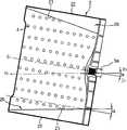
图3是图1中所示的旋转桶的透视图,表示了排列在旋转桶上的提升器的结构;Figure 3 is a perspective view of the rotary bucket shown in Figure 1, showing the structure of the lifters arranged on the rotary bucket;
图4是图2中所示的一个提升器的透视图;Figure 4 is a perspective view of a lifter shown in Figure 2;
图5是沿着图4中的V-V线的剖面示图;Fig. 5 is a sectional view along the line V-V in Fig. 4;
图6是相应于图3的旋转桶的透视图,显示了根据本发明实施例的提升器的结构;FIG. 6 is a perspective view corresponding to the rotary bucket of FIG. 3, showing the structure of a lifter according to an embodiment of the present invention;
图7是图6中所示的一个提升器的视图,显示了具有波形结构的提升器的顶部;Figure 7 is a view of one of the lifters shown in Figure 6, showing the top of the lifter with a wave-like configuration;
图8是沿图7中的VII-VII线的剖面示图,显示了排列在提升器的内部的分隔板。Fig. 8 is a sectional view along line VII-VII in Fig. 7, showing partition plates arranged inside the lifter.
具体实施方式 Detailed ways
以下,参照附图来详细说明本发明的实施例,其例子列举在附图中,其中相同的标号始终表示相同的部件。下面参照附图描述实施例以解释本发明。Embodiments of the present invention will be described in detail below with reference to the accompanying drawings, examples of which are illustrated in the accompanying drawings, in which like reference numerals designate like parts throughout. The embodiments are described below in order to explain the present invention by referring to the figures.
图1是示意性地表示根据本发明的滚筒式洗衣机的结构的截面示图。如图1中所示,为了洗涤和脱水甩干装入旋转桶3中的衣物,根据本发明的滚筒式洗衣机包括:壳体1,近似于盒状,以限定洗衣机的外观;鼓形水桶2,安装于壳体1中并适于容纳洗涤水;鼓形旋转桶3,旋转地位于水桶2中并具有位于旋转桶的外围壁上的离心脱水孔4;和以使旋转桶3旋转的电机5。FIG. 1 is a sectional view schematically showing the structure of a drum type washing machine according to the present invention. As shown in Figure 1, in order to wash and spin dry the clothes loaded into the
在水桶2和旋转桶3各自的前端提供了开口2a和3a,以使得将衣物放入旋转桶3和从旋转桶3中取出。门6以铰链形式安装于壳体1的前壁上,以打开和关闭水桶2和旋转桶3的开口2a和3a。Openings 2 a and 3 a are provided at respective front ends of the water tub 2 and the
壳体1的顶部安装了用来接收来自外部水源的洗涤水供水管7和用来容纳洗涤剂的洗涤剂容器8,并将洗涤剂和经供水管7提供的洗涤水混合。排水泵9和排水管10安装于壳体1的底部,以在完成洗衣循环后向外界排出洗涤水。A washing water supply pipe 7 for receiving from an external water source and a
在水桶2的外面驱动电机5固定地安装在水桶2的后端。其一端连接驱动电机5的旋转轴5a的另一端固定地连接在旋转水桶3的后端,从而将旋转力从驱动电机5传送到旋转桶3,因此使得旋转桶3旋转。The drive motor 5 is fixedly installed on the rear end of the water bucket 2 outside the water bucket 2 . One end of which is connected to the
旋转桶3以一定的角度α(图2)向着壳体1的前壁向上地倾斜,以使用户无需弯腰就可将衣物装入和取出。类似地,水桶2以与旋转桶3的倾斜角α相等的角度向上地倾斜,并悬挂在壳体1中。当然,在某些情况下水桶2和旋转桶3可具有不同的倾斜角。The
其优点是旋转桶3的倾斜角可以尽可能的大,以方便地在壳体1的前面装入和取出衣物。然而,当倾斜角α过大时,位于旋转桶的3的后端部分的衣物的量也过多地增加,从而会发生洗涤性能的恶化。因此,考虑到装入和取出衣物的操作的方便和洗衣性能,最好将旋转桶3的倾斜角α确定在大约5°到15°范围内。Its advantage is that the inclination angle of the
提升器20排列在旋转桶3的内部外围表面上,从而当沿着旋转桶3轴向地伸展时围绕旋转桶3在圆周上彼此间隔均匀地排列。当旋转桶3旋转时,提升器20将旋转桶3中的衣物与洗涤水一起提升,然后在一定的水平面释放提升的衣物和洗涤水,从而抛下衣物和洗涤水。因此,洗涤了衣物。The
由于旋转桶3向着壳体1的前壁向上倾斜的布置,与和门6连接的旋转桶3的前端部分相比,旋转桶3中容纳的衣物可能主要位于与壳体1的后壁相连的旋转桶的后端部分。为了有效地提升处于这种状态的衣物,提升器20具有随着从旋转桶3的后端向着其前端延伸而逐渐降低的高度。将在后面参照图2至5对提升器的这种结构进行描述。Due to the upwardly inclined arrangement of the
图2和3是分别表示图1中所示的排列在旋转桶的内部外围表面上的提升器的结构的截面示图和透视图。2 and 3 are a sectional view and a perspective view, respectively, showing the structure of lifters arranged on the inner peripheral surface of the rotary tub shown in FIG. 1 .
如图2所示,旋转桶3以α角朝着壳体1(图1)的前壁向上倾斜,从而旋转桶的中心轴,即中心线C1-C1,与水平线H1-H1以角度α相交。按照这种布置,与旋转桶3的前端部分相比,相对大量的衣物位于旋转桶3的后端部分。As shown in Fig. 2, the
类似地,每个提升器20具有随着其从旋转桶3的后端向前端延伸具有逐渐减小的高度,从而分别沿着提升器的顶部和底部21和22延伸的线以角度α相交。根据这种结构,当提升器20位于旋转桶3的最低水平面时,提升器20的顶部21与水平线H1-H1平行。Similarly, each
这里,每个提升器20的底部22是与旋转桶3的内部外围表面接触的提升器部分,而每个提升器20的顶部21是与旋转桶3的内部外围表面离开最大距离的提升器部分。Here, the bottom 22 of each
按照其这种结构,当位于旋转桶3的最低水平面时,提升器20在其具有相对大的高度的后端部分可以提升起相对大量的衣物,而在起具有相对小的高度的后端部分提升相对小量的衣物。因此,旋转桶3被维持在动态平衡状态。所以可以在平稳旋转时均匀的洗涤所有的衣物。According to its structure, when located at the lowest level of the
由于在洗涤过程中,相对小量的衣物分布在具有相对小的高度的提升器20的前端部分,因此不会发生位于提升器20的前端部分的衣物向着旋转桶3的后端部分的移动。Since a relatively small amount of laundry is distributed at the front end portion of the
如图3中所示,提升器20围绕着旋转桶3排列,当从旋转桶3的后端向其前端轴向延伸时,即贯穿于旋转桶3的整个长度,它们在圆周上彼此均匀的隔开。因此,提升器20可以有效地提升容纳在旋转桶3中的所有衣物。As shown in Figure 3, the
每个提升器20的顶部21具有不变的宽度,且具有喷水孔23。喷水孔23纵向排列为几行。The top 21 of each
每个提升器20还具有用以喷洒洗涤水的结构。即,每个提升器20具有向下敞开的中空结构以在其内部接收洗涤水。另外,在旋转桶3与提升器20中的一个相连的部分提供了开口27。此外,每个提升器20的底部22是敞开的以和与其连接的开口27连通。当提升器20位于其最低水平面时,可通过与其相连的开口27和其打开的较低端22将洗涤水引入提升器20的内部。Each
因此,经在旋转桶3的底端的敞开的提升器的底部22引入各提升器20内部的洗涤水通过在旋转桶3的顶部的喷水孔23向下喷洒。因此,与洗涤剂混合的洗涤水可以渗透衣物,从而可以快速地洗涤衣物。Therefore, the wash water introduced into the inside of each
尽管没有在图中表示,但是可以在各提升器20的对应端部分提供喷水孔,以从侧面喷洒洗涤水。Although not shown in the drawings, water spray holes may be provided at corresponding end portions of each
如图4和5中所示,在每个提升器20的内部提供了一对凸台24从而使它们和提升器成为一体。凸台24从提升器20的顶部21的内部表面向下凸出。在每个凸台24的凸出端形成螺纹连接孔25。因此,可以在旋转桶3的外边通过将连接螺钉26穿过备个连接孔25将提升器20安装在旋转桶3上。As shown in Figures 4 and 5, a pair of
同时,因为由于提升器20具有向着旋转桶3的前端逐渐减小的高度,根据运动提升器20的前端部分比提升器20的后端部分位于更高的水平面,随着提升器从旋转桶3的底部向其顶部移动,经在旋转桶3的底部的提升器20的敞开的底部22引入各个提升器20的内部的洗涤水可能向着提升器20的后端部分流动。结果,相对小量的洗涤水通过在提升器20的前端部分的喷水孔23喷洒。相反,洗涤水主要通过在提升器20的后端部分的喷水孔23喷洒。Simultaneously, because the front end portion of the
为了避免这种现象,每个提升器具有排列其内部的分隔板。以下将参照显示了一个提升器的内部结构的图4和5描述这种结构。In order to avoid this phenomenon, each riser has partition plates lining its interior. This structure will be described below with reference to Figures 4 and 5 showing the internal structure of a lifter.
参照图4和5,根据本发明的提升器20包括:第一和第二分隔板31和32,排列在提升器20的内部,以当纵向地彼此隔开一定距离时横向伸展。提升器20的内部被分隔板31和32分为第一到第三室41至43。Referring to FIGS. 4 and 5 , the
由于第一分隔板31,当关联的提升器20位于旋转桶3的顶端时,位于相对高的水平面的第一室41容纳的洗涤水不会流向第二室42。同样,由于第二分隔板32,第二室42容纳的洗涤水不会流向第三室43。Due to the
因此,在提升器20的前端的第一室41容纳的洗涤水只喷洒在旋转桶3的前端部分,而在提升器20的中部的第二室42容纳的洗涤水只喷洒在旋转桶的中部。同样,在提升器20的后端部分的第三室43容纳的洗涤水只喷洒在旋转桶3的后端部分。Therefore, the washing water contained in the
为了从第一至第三室41至43中分别喷洒出大约等量的洗涤水,排列第一和第二分隔板31和32以适当地分隔提升器20的内部,从而第一至第三室41至43具有大约相等的容积。为此,第一和第二分隔板31和32向着提升器20的前端倾斜,从而每个分隔板的上端比分隔板的下端离提升器20的前端更近。另外,第一和第二分隔板31和32分别具有不同的倾角。In order to spray approximately equal amounts of wash water from the first to
根据这种安排,第一和第二分隔板31和32将提升器20的顶部21分为三个分别具有不同但大约相等的长度的部分。第一和第二分隔板31和32的较低端将提升器20的底部22分为三部分,从而相应于第一室41的部分具有最大的长度,相应于第三室43的部分具有最小的长度。因此,第一至第三室41至43分别具有大约相等的容积。According to this arrangement, the first and
尽管提升器被描述为具有被两个隔板31和33所限定的三个室41至43的结构,但是可以通过在提升器内部排列更多数目的分隔板来限定更多数目的室。在这种情况下,可通过在提升器顶部形成的所有喷水孔来更均匀地喷洒与洗涤剂混合的洗涤水。Although the riser is described as having a structure of three
现在,将描述通过具有根据本发明的上述结构的滚筒式洗衣机洗涤衣物的过程。Now, a process of washing laundry by the drum type washing machine having the above structure according to the present invention will be described.
首先,用户打开门6,将衣物放入向上倾斜的旋转桶3中。此时,用户可以无需降低其姿势方便地进行这些操作。衣物分布在旋转桶3中,从而相对大量的衣物位于旋转桶3的后端部分,而相对小量的衣物位于旋转桶3的前端部分。First, the user opens the door 6 and puts the laundry into the upwardly inclined
其后,用户关上门6,并操作控制板(未表示)以运转洗衣机。随着洗衣机的运转,开始供水循环。即,经供水管7和洗涤剂容器8引入混合有洗涤剂的洗涤水,从而充注旋转桶2的底部。当供给了和衣物量相应的希望的水量时,供水循环完成。供水循环完成后,驱动电机5与旋转轴5a一起以顺时针和逆时针方向交替旋转。因此,洗涤了旋转桶3中容纳的衣物。Thereafter, the user closes the door 6, and operates a control panel (not shown) to operate the washing machine. With the washing machine running, the water supply cycle begins. That is, wash water mixed with detergent is introduced through the water supply pipe 7 and the
尽管在洗涤循环过程中相对大量的衣物位于旋转桶3的后端部分,由于其具有其后端部分比其前端部分较高的高度,提升器20可以毫无问题地提升起衣物,从而有效地洗涤衣物。此外,旋转桶3可以在动态平衡状态下旋转。Although a relatively large amount of laundry is located at the rear end portion of the
当提升器20提升衣物按照旋转桶的旋转,连续移动到与旋转桶3的顶部连接的水平面时,衣物被从提升器20释放,然后抛下,从而被洗涤。同时,通过在旋转桶3的底端的提升器的底部22引入混合有洗涤剂的洗涤水,然后通过在提升器20的顶部21提供的喷水孔23向下喷洒,从而浸入衣物。When the lifter 20 lifts the laundry to continuously move to a level connected to the top of the
此时,由于分别具有大约相等体积的第一至第三室41至43在提升器20的内部通过第一和第二分隔板31和32是相互分离的,因此,洗涤水不从提升器20的前端部分流向其后端部分。At this time, since the first to
即,容纳在第一室41的洗涤水只通过形成于提升器20前端部分的喷水孔23喷洒,而容纳在第二室42的洗涤水只通过形成于提升器20的中间部分的喷水孔23喷洒。同样,容纳在第三室43中的洗涤水只通过形成于提升器20的后端部分的喷水孔23喷洒。That is, the wash water contained in the
因此,洗涤水可以在提升器的整个长度上均匀地喷洒。从而,混合有洗涤剂的洗涤水不仅充分地喷洒在位于旋转桶3后端的衣物上,而且充分喷洒在位于旋转桶3中部和前端的衣物上,因此所有部分的衣物被洗涤水均匀浸湿。Therefore, wash water can be evenly sprayed over the entire length of the lifter. Thus, the washing water mixed with detergent is fully sprayed not only on the clothes at the rear end of the
洗涤循环完成后,通过漂洗和脱水循环将衣物漂洗干净并甩干。因此,完成衣物的洗涤。在漂洗循环中,根据第一和第二分隔板31和32的功能和效果,所有的衣物也可以被均匀地漂洗。After the wash cycle is complete, rinse and spin dry the laundry with the rinse and spin cycle. Thus, the washing of the laundry is completed. In the rinsing cycle, according to the functions and effects of the first and
衣物的洗涤完成后,用户再次打开门6,并从旋转桶3中取出衣物。此时,由于旋转桶3向上倾斜,用户可以不用太弯腰就可以方便地进行这些操作。After the washing of the clothes is completed, the user opens the door 6 again and takes out the clothes from the
图6至8分别表示根据本发明另一实施例的提升器的结构。图6表示排列在旋转桶的内部表面上的提升器。图7表示在其顶部具有波形表面的提升器。图8表示排列在提升器内部的分隔板。6 to 8 respectively show the structure of a lifter according to another embodiment of the present invention. Figure 6 shows lifters arranged on the inner surface of the rotating tub. Figure 7 shows a riser with a corrugated surface at its top. Figure 8 shows the divider panels arranged inside the riser.
参照图6和7,除了其表面即其顶部21具有包括交替排列并分别具有圆弧表面的凹槽和凸起的波形结构外,提升器20a具有与图3中所示的提升器相似的结构。Referring to FIGS. 6 and 7, except that its surface, that is, its top 21 has a corrugated structure including grooves and protrusions arranged alternately and respectively having arcuate surfaces, the lifter 20a has a structure similar to that of the lifter shown in FIG. 3 .
即,提升器20a的顶部21具有向着旋转桶3的前端逐渐减小的高度的倾斜结构。脊部21a和槽底21b也在提升器21a的顶部21上以一定的间距交替排列。此外,在波形顶部21上提供了喷水孔23从而纵向地排列为几行。在各行中相应的喷水孔在各脊部21a和各槽底21b中横向地排列。That is, the top 21 of the lifter 20 a has an inclined structure with a gradually decreasing height toward the front end of the
由于提升器在其顶部21上具有包括脊部21a和槽底21b的波形结构,引入提升器20a内部的洗涤水停留在提升器20a的内部由脊部21a所限定的空间中,而不会立即从提升器20a的前端部分流向其后端部分,并通过喷水孔23向着旋转桶3的底部连续地喷洒。因此,即使在提升器20a的前端部分也有足够量的洗涤水可以喷洒。Since the lifter has a wave structure including ridges 21a and groove bottoms 21b on its top 21, the wash water introduced into the inside of the lifter 20a stays in the space defined by the ridges 21a inside the lifter 20a without immediately It flows from the front end portion of the lifter 20 a to its rear end portion, and continuously sprays toward the bottom of the
另外,由于喷水孔23沿着脊部21a和槽底21b按行纵向地排列,还没有通过处于比另一脊部21a高的水平面的喷水孔23被排出的洗涤水,流向下一个水平的脊部21a,并通过下一个水平面的脊部21a的喷水孔23排出。In addition, since the water spray holes 23 are longitudinally arranged in rows along the ridge 21a and the groove bottom 21b, the wash water that has not been discharged through the water spray holes 23 at a level higher than the other ridge 21a flows to the next level. ridge 21a of the next horizontal plane, and is discharged through the
因此,洗涤水不会从提升器20a的前端立即流向其后端,从而不是被主要地只喷洒在提升器20a的后端。Therefore, the wash water does not immediately flow from the front end of the lifter 20a to the rear end thereof, so as not to be mainly sprayed only on the rear end of the lifter 20a.
由于提升器20a的顶部21具有波形结构,在旋转桶3以顺时针和逆时针交替旋转的过程中,摩擦力施加于衣物。Since the top 21 of the lifter 20a has a wave structure, frictional force is applied to the laundry during the rotation of the
同时,如图8中所示,提升器20a可包括:在其顶部21上的圆弧形脊部21a和圆弧形槽底21b,同时还包括在其内部的分隔板,例如,图4和5的分隔板31和32。Meanwhile, as shown in FIG. 8, the lifter 20a may include: a circular arc-shaped ridge 21a and a circular arc-shaped groove bottom 21b on its top 21, while also including a partition plate inside it, for example, FIG. 4 and 5
采用提升器20a的这种结构,在提升器20a中接收的洗涤水主要停留在由脊部21a在提升器20a的内部所限定的空间中,减慢了洗涤水从而向着提升器20a的较低水平面部分的流动。此外,由于第一和第二分隔板31和32,洗涤水不再流向提升器20a的较低水平面部分。因此,可以更有效地防止洗涤水从提升器20a的前端部分流向其后端部分。With this structure of the lifter 20a, the wash water received in the lifter 20a mainly stays in the space defined by the ridge 21a inside the lifter 20a, slowing down the wash water so as to flow toward the lower portion of the lifter 20a. Flow in the horizontal section. In addition, due to the first and
从上述的描述显然可知,在根据本发明的一方面的滚筒式洗衣机中,旋转桶向着壳体的前壁向上地倾斜,从旋转桶的内部外围表面突出的每个提升器具有当其位于旋转桶的最低水平面时其顶部维持水平的结构。因此,即使当相对大量的衣物分布于旋转桶的后端部分时,也可能毫无问题地提升衣物,从而快速并有效地洗涤衣物。As apparent from the above description, in the drum type washing machine according to an aspect of the present invention, the rotary tub is inclined upward toward the front wall of the housing, and each lifter protruding from the inner peripheral surface of the rotary tub has a The lowest level of the bucket is when its top maintains a horizontal structure. Therefore, even when a relatively large amount of laundry is distributed in the rear end portion of the rotary tub, it is possible to lift the laundry without any problem, thereby washing the laundry quickly and efficiently.
由于在根据本发明的滚筒式洗衣机中的这种结构,可通过提升器稳定地提升衣物。因此,旋转桶可在动态稳定的状态下旋转。Due to this structure in the drum type washing machine according to the present invention, laundry can be stably lifted by the lifter. Therefore, the rotary tub can rotate in a dynamically stable state.
另外,衣物不会缠绕或结块。因此,在脱水过程中旋转桶在平衡状态下旋转。也没必要将被洗涤的衣物解开缠绕。Plus, laundry won't tangle or clump. Therefore, the rotary tub rotates in a balanced state during the dehydration process. There is also no need to untangle the laundry being washed.
在根据本发明的另一方面的滚筒式洗衣机中,分隔板被排列于每个提升器中,以在提升器的内部限定分别具有大约相等容积的室。由于这种结构,混合有洗涤剂的洗涤水可以在提升器的整个长度上均匀的喷洒。因此,快速地并有效地洗涤甚至分布在位于相对高的水平面的旋转桶的前端部分的衣物成为可能。In a drum type washing machine according to another aspect of the present invention, a partition plate is arranged in each lifter to define chambers respectively having approximately equal volumes inside the lifter. Due to this structure, the washing water mixed with detergent can be evenly sprayed over the entire length of the lifter. Therefore, it becomes possible to quickly and efficiently wash even the laundry distributed at the front end portion of the rotary tub located at a relatively high level.
在根据本发明的另一方面的滚筒式洗衣机中,每个提升器在其顶部具有波形结构。喷水孔在波形结构的脊部和槽底中按行排列。只使用这种结构或与多个分隔板一起使用,在提升器的整个长度上均匀地喷洒混合有洗涤剂的洗涤水,同时对衣物施加摩擦力是可能的。因此,可以更快和更有效地洗涤衣物。In the drum type washing machine according to another aspect of the present invention, each lifter has a wave structure at its top. The water spray holes are arranged in rows in the ridges and groove bottoms of the corrugated structure. Using this structure alone or in combination with a plurality of partition plates, it is possible to uniformly spray wash water mixed with detergent over the entire length of the lifter while applying friction to the clothes. Therefore, laundry can be washed more quickly and efficiently.
尽管已表示和描述了本发明的一些实施例,但是本领域的技术人员应该理解,在不脱离本发明的原理和精神,以及由权利要求和其等同物所限定的范围的情况下,可对实施例进行改动。Although some embodiments of the present invention have been shown and described, it should be understood by those skilled in the art that, without departing from the principle and spirit of the present invention and the scope defined by the claims and their equivalents, the Examples are modified.
Claims (24)
Applications Claiming Priority (6)
| Application Number | Priority Date | Filing Date | Title |
|---|---|---|---|
| KR79248/2003 | 2003-11-10 | ||
| KR1020030079250AKR20050045257A (en) | 2003-11-10 | 2003-11-10 | Drum washing machine |
| KR1020030079252AKR20050045259A (en) | 2003-11-10 | 2003-11-10 | Drum washing machine |
| KR79252/2003 | 2003-11-10 | ||
| KR79250/2003 | 2003-11-10 | ||
| KR1020030079248AKR20050045255A (en) | 2003-11-10 | 2003-11-10 | Drum washing machine |
Publications (1)
| Publication Number | Publication Date |
|---|---|
| CN1616748Atrue CN1616748A (en) | 2005-05-18 |
Family
ID=34437615
Family Applications (1)
| Application Number | Title | Priority Date | Filing Date |
|---|---|---|---|
| CNA2004100707201APendingCN1616748A (en) | 2003-11-10 | 2004-07-22 | front load washing machine |
Country Status (4)
| Country | Link |
|---|---|
| US (1) | US20050097927A1 (en) |
| EP (1) | EP1529866A1 (en) |
| JP (1) | JP4105134B2 (en) |
| CN (1) | CN1616748A (en) |
Cited By (12)
| Publication number | Priority date | Publication date | Assignee | Title |
|---|---|---|---|---|
| CN101871157A (en)* | 2009-04-24 | 2010-10-27 | 海尔集团公司 | Water-repelling leaf with spray structure and drum washing machine adopting the water-repelling leaf |
| CN101089277B (en)* | 2006-06-15 | 2011-12-21 | Lg电子株式会社 | Washer and method of forming drum thereof |
| CN103114414A (en)* | 2012-11-09 | 2013-05-22 | 无锡爱博金属制品有限公司 | Washing machine inner barrel |
| CN104131438A (en)* | 2013-04-30 | 2014-11-05 | Lg电子株式会社 | Washing machine |
| CN106498658A (en)* | 2015-09-04 | 2017-03-15 | Lg电子株式会社 | Clothes treatment device |
| WO2019007432A1 (en)* | 2017-07-07 | 2019-01-10 | 青岛海尔滚筒洗衣机有限公司 | Water agitation blade of washing machine, and washing machine |
| CN109423817A (en)* | 2017-08-31 | 2019-03-05 | 青岛海尔洗衣机有限公司 | A kind of use in washing machine inner cylinder lifting rib and washing machine |
| CN110499623A (en)* | 2018-05-18 | 2019-11-26 | 青岛海尔洗衣机有限公司 | Clothes treatment bucket and clothes treatment device |
| CN111519379A (en)* | 2019-02-01 | 2020-08-11 | Lg电子株式会社 | Clothes treating apparatus |
| US11414802B2 (en) | 2019-02-01 | 2022-08-16 | Lg Electronics Inc. | Laundry treating apparatus |
| CN116377688A (en)* | 2023-04-27 | 2023-07-04 | 长虹美菱股份有限公司 | A drum washing machine |
| US12227890B2 (en) | 2019-02-01 | 2025-02-18 | Lg Electronics Inc. | Laundry treating apparatus |
Families Citing this family (34)
| Publication number | Priority date | Publication date | Assignee | Title |
|---|---|---|---|---|
| JPH06287963A (en)* | 1993-04-01 | 1994-10-11 | Ito Komuten:Kk | Connecting joint member for foundation concrete block |
| DE102004043716A1 (en)* | 2004-09-09 | 2006-03-16 | BSH Bosch und Siemens Hausgeräte GmbH | Method for fastening plastic drivers in laundry drums |
| ES2276627B1 (en)* | 2005-12-02 | 2008-04-16 | Bsh Electrodomesticos España, S.A. | WASHER DRUM. |
| ATE463602T1 (en)* | 2006-02-02 | 2010-04-15 | Electrolux Home Prod Corp | CARRIER OF A DRUM OF A LAUNDRY WASHING MACHINE |
| DE102007004056B4 (en)* | 2007-01-22 | 2010-08-05 | Miele & Cie. Kg | Washing machine comprising a washing unit with a tub in which a rotatably mounted drum is arranged |
| KR101136863B1 (en) | 2007-02-28 | 2012-04-20 | 삼성전자주식회사 | Washing machine |
| CN101668891A (en)* | 2007-05-14 | 2010-03-10 | 大宇电子株式会社 | washing machine having filtering lifters |
| ES2361719T3 (en)* | 2007-12-28 | 2011-06-21 | Arçelik Anonim Sirketi | WASHER WITH COMPENSATION DEPOSITS IN THE WASHING NERVADURAS AND SPRAYERS. |
| ES2332346B1 (en)* | 2008-03-03 | 2011-02-02 | Bsh Electrodomesticos España, S.A. | WASHER DRUM. |
| DE602008001669D1 (en)* | 2008-06-24 | 2010-08-12 | Candy Spa | Device for dispensing washing and / or cleaning liquid into a washing machine rotating drum |
| KR101604688B1 (en)* | 2009-05-04 | 2016-03-18 | 엘지전자 주식회사 | Laundry machine |
| KR101643860B1 (en)* | 2009-12-24 | 2016-07-29 | 엘지전자 주식회사 | Washing machine |
| DK2363523T3 (en)* | 2010-02-12 | 2014-08-11 | Asko Appliances Ab | Drum carrier for a washing machine |
| US9003838B2 (en) | 2010-12-08 | 2015-04-14 | Whirlpool Corporation | Laundry treating appliance with balancing system |
| US8991223B2 (en)* | 2010-12-08 | 2015-03-31 | Whirlpool Corporation | Laundry treating appliance with balancing system |
| JP5537514B2 (en)* | 2011-08-29 | 2014-07-02 | 日立アプライアンス株式会社 | Drum washing machine |
| USD664727S1 (en)* | 2011-10-06 | 2012-07-31 | Samsung Electronics Co., Ltd. | Lifter for washing machine |
| USD722212S1 (en)* | 2012-11-05 | 2015-02-03 | Samsung Electronics Co., Ltd. | Drum for washing machine |
| USD720902S1 (en)* | 2012-11-26 | 2015-01-06 | Samsung Electronics Co., Ltd. | Drum for washing machine |
| USD713105S1 (en)* | 2013-01-02 | 2014-09-09 | General Electric Company | Lifter for a basket of an appliance |
| USD700411S1 (en)* | 2013-02-07 | 2014-02-25 | Lg Electronics Inc. | Drum for washing machine |
| EP2765234B1 (en)* | 2013-02-07 | 2017-08-23 | Whirpool Corporation | Domestic clothes dryer and method for driving such dryer |
| USD748356S1 (en)* | 2013-07-16 | 2016-01-26 | Whirlpool Corporation | Container for a clothes washing machine |
| USD761501S1 (en)* | 2013-09-27 | 2016-07-12 | Whirlpool Corporation | Container for clothes washing machine |
| KR101623009B1 (en)* | 2014-07-09 | 2016-05-20 | 동부대우전자 주식회사 | Laundry machine and laundry method |
| KR102449509B1 (en) | 2016-01-05 | 2022-09-29 | 엘지전자 주식회사 | Lifter for clothes handling equipment |
| KR102557928B1 (en)* | 2016-08-04 | 2023-07-21 | 삼성전자주식회사 | Lifter and washing machine having the same |
| KR102493162B1 (en)* | 2017-11-08 | 2023-01-27 | 엘지전자 주식회사 | Laundry treating appratus and controlling method thereof |
| USD901111S1 (en)* | 2018-12-03 | 2020-11-03 | Samsung Electronics Co., Ltd. | Lifter for washing machine |
| TR201819826A2 (en) | 2018-12-19 | 2020-07-21 | Arcelik As | WASHING MACHINE WITH SHOWER FEATURED DRUM BLADE |
| TR201903848A2 (en) | 2019-03-14 | 2020-09-21 | Arcelik As | WASHING MACHINE WITH SHOWER FEATURED DRUM BLADE |
| CN112111928B (en)* | 2019-06-19 | 2022-07-12 | 青岛海尔洗衣机有限公司 | Lifting rib of a washing machine and washing machine |
| CN112481941B (en)* | 2019-09-11 | 2023-09-19 | 青岛海尔智能技术研发有限公司 | drum washing machine |
| CN111286933A (en)* | 2020-02-14 | 2020-06-16 | 海信(山东)冰箱有限公司 | Washing machine |
Family Cites Families (8)
| Publication number | Priority date | Publication date | Assignee | Title |
|---|---|---|---|---|
| US1389182A (en)* | 1920-03-31 | 1921-08-30 | Binder Gottlob | Rotary washing-machine |
| GB1344996A (en)* | 1970-12-02 | 1974-01-23 | Broadbent & Sons Ltd Thomas | Lifter for a centrifugal machine |
| US4971449A (en)* | 1989-12-19 | 1990-11-20 | American Laundry Machinery Inc. | Drum type agitating and mixing machine |
| US5881579A (en)* | 1997-05-05 | 1999-03-16 | Maytag Corporation | Door boot with varying angle lip seal |
| DE19859571A1 (en)* | 1998-12-22 | 2000-06-29 | Bsh Bosch Siemens Hausgeraete | Laundry drum |
| DE19925917A1 (en)* | 1999-06-07 | 2000-12-14 | Bsh Bosch Siemens Hausgeraete | Front loading washing machine with a rotating drum |
| JP3877543B2 (en)* | 2001-04-20 | 2007-02-07 | 三洋電機株式会社 | Drum washing machine |
| JP3772821B2 (en)* | 2001-10-23 | 2006-05-10 | エルジー電子株式会社 | Washing machine |
- 2004
- 2004-07-09EPEP04254132Apatent/EP1529866A1/ennot_activeWithdrawn
- 2004-07-09USUS10/886,709patent/US20050097927A1/ennot_activeAbandoned
- 2004-07-22CNCNA2004100707201Apatent/CN1616748A/enactivePending
- 2004-08-24JPJP2004244203Apatent/JP4105134B2/ennot_activeExpired - Fee Related
Cited By (16)
| Publication number | Priority date | Publication date | Assignee | Title |
|---|---|---|---|---|
| CN101089277B (en)* | 2006-06-15 | 2011-12-21 | Lg电子株式会社 | Washer and method of forming drum thereof |
| CN101871157A (en)* | 2009-04-24 | 2010-10-27 | 海尔集团公司 | Water-repelling leaf with spray structure and drum washing machine adopting the water-repelling leaf |
| CN101871157B (en)* | 2009-04-24 | 2013-12-11 | 海尔集团公司 | Water spinning blade with spraying structure and rotary drum washing machine having the same |
| CN103114414A (en)* | 2012-11-09 | 2013-05-22 | 无锡爱博金属制品有限公司 | Washing machine inner barrel |
| CN104131438A (en)* | 2013-04-30 | 2014-11-05 | Lg电子株式会社 | Washing machine |
| US9347165B2 (en) | 2013-04-30 | 2016-05-24 | Lg Electronics Inc. | Washing machine |
| CN106498658A (en)* | 2015-09-04 | 2017-03-15 | Lg电子株式会社 | Clothes treatment device |
| WO2019007432A1 (en)* | 2017-07-07 | 2019-01-10 | 青岛海尔滚筒洗衣机有限公司 | Water agitation blade of washing machine, and washing machine |
| CN109423817A (en)* | 2017-08-31 | 2019-03-05 | 青岛海尔洗衣机有限公司 | A kind of use in washing machine inner cylinder lifting rib and washing machine |
| CN109423817B (en)* | 2017-08-31 | 2022-04-22 | 青岛海尔洗衣机有限公司 | Inner tube promotes muscle and washing machine for washing machine |
| CN110499623A (en)* | 2018-05-18 | 2019-11-26 | 青岛海尔洗衣机有限公司 | Clothes treatment bucket and clothes treatment device |
| CN111519379A (en)* | 2019-02-01 | 2020-08-11 | Lg电子株式会社 | Clothes treating apparatus |
| US11414802B2 (en) | 2019-02-01 | 2022-08-16 | Lg Electronics Inc. | Laundry treating apparatus |
| CN111519379B (en)* | 2019-02-01 | 2022-10-28 | Lg电子株式会社 | Clothes treating apparatus |
| US12227890B2 (en) | 2019-02-01 | 2025-02-18 | Lg Electronics Inc. | Laundry treating apparatus |
| CN116377688A (en)* | 2023-04-27 | 2023-07-04 | 长虹美菱股份有限公司 | A drum washing machine |
Also Published As
| Publication number | Publication date |
|---|---|
| JP2005137889A (en) | 2005-06-02 |
| EP1529866A1 (en) | 2005-05-11 |
| JP4105134B2 (en) | 2008-06-25 |
| US20050097927A1 (en) | 2005-05-12 |
Similar Documents
| Publication | Publication Date | Title |
|---|---|---|
| CN1616748A (en) | front load washing machine | |
| CN1616747A (en) | front load washing machine | |
| CN102597354B (en) | Clothes treating device and clothes treating method | |
| US9347165B2 (en) | Washing machine | |
| CN1201043C (en) | washing machine | |
| CN1063810C (en) | Vertical axis washer | |
| CN1239773C (en) | washing machine | |
| CN1707009A (en) | front load washing machine | |
| CN1580374A (en) | Washing machine | |
| US20050022565A1 (en) | Washing machine | |
| CN1609324A (en) | front load washing machine | |
| CN1111697A (en) | A method of washing in a vertical axis washer | |
| CN1111695A (en) | A method of rinsing in a vertical axis washer | |
| CN1081695C (en) | Washing machine | |
| CN102587070A (en) | Washing machine and pulsator thereof | |
| CN1773000A (en) | front load washing machine | |
| WO2019120117A1 (en) | Laundry washing machine | |
| CN1696380A (en) | Method for controlling dehydration of washing machine | |
| CN1137587A (en) | Washing machine having detachable washing bucket | |
| EP1876282A1 (en) | Basket for washing or drying machines | |
| JP2009254614A (en) | Drum drying machine and drum washing/drying machine | |
| CN1196416A (en) | Washer | |
| CN1827897A (en) | Washing machine and washer dryer | |
| JP5386022B1 (en) | Washing machine | |
| CN1749471A (en) | front load washing machine |
Legal Events
| Date | Code | Title | Description |
|---|---|---|---|
| C06 | Publication | ||
| PB01 | Publication | ||
| C10 | Entry into substantive examination | ||
| SE01 | Entry into force of request for substantive examination | ||
| C12 | Rejection of a patent application after its publication | ||
| RJ01 | Rejection of invention patent application after publication |