CN1605790B - LED light apparatus and method therefor - Google Patents
LED light apparatus and method thereforDownload PDFInfo
- Publication number
- CN1605790B CN1605790BCN2004100903315ACN200410090331ACN1605790BCN 1605790 BCN1605790 BCN 1605790BCN 2004100903315 ACN2004100903315 ACN 2004100903315ACN 200410090331 ACN200410090331 ACN 200410090331ACN 1605790 BCN1605790 BCN 1605790B
- Authority
- CN
- China
- Prior art keywords
- led
- lighting device
- light
- led lighting
- surface profile
- Prior art date
- Legal status (The legal status is an assumption and is not a legal conclusion. Google has not performed a legal analysis and makes no representation as to the accuracy of the status listed.)
- Expired - Fee Related
Links
Images


Classifications
- F—MECHANICAL ENGINEERING; LIGHTING; HEATING; WEAPONS; BLASTING
- F21—LIGHTING
- F21V—FUNCTIONAL FEATURES OR DETAILS OF LIGHTING DEVICES OR SYSTEMS THEREOF; STRUCTURAL COMBINATIONS OF LIGHTING DEVICES WITH OTHER ARTICLES, NOT OTHERWISE PROVIDED FOR
- F21V7/00—Reflectors for light sources
- F21V7/04—Optical design
- F21V7/041—Optical design with conical or pyramidal surface
- F—MECHANICAL ENGINEERING; LIGHTING; HEATING; WEAPONS; BLASTING
- F21—LIGHTING
- F21K—NON-ELECTRIC LIGHT SOURCES USING LUMINESCENCE; LIGHT SOURCES USING ELECTROCHEMILUMINESCENCE; LIGHT SOURCES USING CHARGES OF COMBUSTIBLE MATERIAL; LIGHT SOURCES USING SEMICONDUCTOR DEVICES AS LIGHT-GENERATING ELEMENTS; LIGHT SOURCES NOT OTHERWISE PROVIDED FOR
- F21K9/00—Light sources using semiconductor devices as light-generating elements, e.g. using light-emitting diodes [LED] or lasers
- H—ELECTRICITY
- H10—SEMICONDUCTOR DEVICES; ELECTRIC SOLID-STATE DEVICES NOT OTHERWISE PROVIDED FOR
- H10H—INORGANIC LIGHT-EMITTING SEMICONDUCTOR DEVICES HAVING POTENTIAL BARRIERS
- H10H20/00—Individual inorganic light-emitting semiconductor devices having potential barriers, e.g. light-emitting diodes [LED]
- H10H20/80—Constructional details
- H10H20/85—Packages
- H10H20/858—Means for heat extraction or cooling
- F—MECHANICAL ENGINEERING; LIGHTING; HEATING; WEAPONS; BLASTING
- F21—LIGHTING
- F21Y—INDEXING SCHEME ASSOCIATED WITH SUBCLASSES F21K, F21L, F21S and F21V, RELATING TO THE FORM OR THE KIND OF THE LIGHT SOURCES OR OF THE COLOUR OF THE LIGHT EMITTED
- F21Y2105/00—Planar light sources
- F21Y2105/10—Planar light sources comprising a two-dimensional array of point-like light-generating elements
- F—MECHANICAL ENGINEERING; LIGHTING; HEATING; WEAPONS; BLASTING
- F21—LIGHTING
- F21Y—INDEXING SCHEME ASSOCIATED WITH SUBCLASSES F21K, F21L, F21S and F21V, RELATING TO THE FORM OR THE KIND OF THE LIGHT SOURCES OR OF THE COLOUR OF THE LIGHT EMITTED
- F21Y2115/00—Light-generating elements of semiconductor light sources
- F21Y2115/10—Light-emitting diodes [LED]
- H—ELECTRICITY
- H01—ELECTRIC ELEMENTS
- H01L—SEMICONDUCTOR DEVICES NOT COVERED BY CLASS H10
- H01L2224/00—Indexing scheme for arrangements for connecting or disconnecting semiconductor or solid-state bodies and methods related thereto as covered by H01L24/00
- H01L2224/01—Means for bonding being attached to, or being formed on, the surface to be connected, e.g. chip-to-package, die-attach, "first-level" interconnects; Manufacturing methods related thereto
- H01L2224/42—Wire connectors; Manufacturing methods related thereto
- H01L2224/47—Structure, shape, material or disposition of the wire connectors after the connecting process
- H01L2224/48—Structure, shape, material or disposition of the wire connectors after the connecting process of an individual wire connector
- H01L2224/481—Disposition
- H01L2224/48151—Connecting between a semiconductor or solid-state body and an item not being a semiconductor or solid-state body, e.g. chip-to-substrate, chip-to-passive
- H01L2224/48221—Connecting between a semiconductor or solid-state body and an item not being a semiconductor or solid-state body, e.g. chip-to-substrate, chip-to-passive the body and the item being stacked
- H01L2224/48225—Connecting between a semiconductor or solid-state body and an item not being a semiconductor or solid-state body, e.g. chip-to-substrate, chip-to-passive the body and the item being stacked the item being non-metallic, e.g. insulating substrate with or without metallisation
- H01L2224/48227—Connecting between a semiconductor or solid-state body and an item not being a semiconductor or solid-state body, e.g. chip-to-substrate, chip-to-passive the body and the item being stacked the item being non-metallic, e.g. insulating substrate with or without metallisation connecting the wire to a bond pad of the item
- H—ELECTRICITY
- H01—ELECTRIC ELEMENTS
- H01L—SEMICONDUCTOR DEVICES NOT COVERED BY CLASS H10
- H01L25/00—Assemblies consisting of a plurality of semiconductor or other solid state devices
- H01L25/03—Assemblies consisting of a plurality of semiconductor or other solid state devices all the devices being of a type provided for in a single subclass of subclasses H10B, H10D, H10F, H10H, H10K or H10N, e.g. assemblies of rectifier diodes
- H01L25/04—Assemblies consisting of a plurality of semiconductor or other solid state devices all the devices being of a type provided for in a single subclass of subclasses H10B, H10D, H10F, H10H, H10K or H10N, e.g. assemblies of rectifier diodes the devices not having separate containers
- H01L25/075—Assemblies consisting of a plurality of semiconductor or other solid state devices all the devices being of a type provided for in a single subclass of subclasses H10B, H10D, H10F, H10H, H10K or H10N, e.g. assemblies of rectifier diodes the devices not having separate containers the devices being of a type provided for in group H10H20/00
- H01L25/0753—Assemblies consisting of a plurality of semiconductor or other solid state devices all the devices being of a type provided for in a single subclass of subclasses H10B, H10D, H10F, H10H, H10K or H10N, e.g. assemblies of rectifier diodes the devices not having separate containers the devices being of a type provided for in group H10H20/00 the devices being arranged next to each other
- Y—GENERAL TAGGING OF NEW TECHNOLOGICAL DEVELOPMENTS; GENERAL TAGGING OF CROSS-SECTIONAL TECHNOLOGIES SPANNING OVER SEVERAL SECTIONS OF THE IPC; TECHNICAL SUBJECTS COVERED BY FORMER USPC CROSS-REFERENCE ART COLLECTIONS [XRACs] AND DIGESTS
- Y10—TECHNICAL SUBJECTS COVERED BY FORMER USPC
- Y10S—TECHNICAL SUBJECTS COVERED BY FORMER USPC CROSS-REFERENCE ART COLLECTIONS [XRACs] AND DIGESTS
- Y10S362/00—Illumination
- Y10S362/80—Light emitting diode
Landscapes
- Engineering & Computer Science (AREA)
- General Engineering & Computer Science (AREA)
- Microelectronics & Electronic Packaging (AREA)
- Physics & Mathematics (AREA)
- Optics & Photonics (AREA)
- Power Engineering (AREA)
- Condensed Matter Physics & Semiconductors (AREA)
- General Physics & Mathematics (AREA)
- Computer Hardware Design (AREA)
- Led Device Packages (AREA)
- Non-Portable Lighting Devices Or Systems Thereof (AREA)
- Arrangement Of Elements, Cooling, Sealing, Or The Like Of Lighting Devices (AREA)
- Fastening Of Light Sources Or Lamp Holders (AREA)
Abstract
Description
Translated fromChinese技术领域technical field
本申请通常涉及LED照明产品。This application generally relates to LED lighting products.
背景技术Background technique
发光二极管(LED)已在需要相对低能量的指示灯、数值读出装置等的应用中使用了数十年。然而,近些年来,单个LED的亮度和功率已充分增大,导致可获得具有1瓦和5瓦的装置。Light emitting diodes (LEDs) have been used for decades in applications requiring relatively low energy indicator lights, numerical readouts, and the like. In recent years, however, the brightness and power of individual LEDs has increased sufficiently that devices with 1 and 5 watts are available.
而小LED相比于传统的照明产品显示出高功效和较长预期寿命。例如,典型的白炽灯泡的功效为10-12流明/瓦,并可持续照明1000至2000小时;普通的荧光灯泡的功效为40-80流明/瓦,并可持续照明10000至20000小时;典型的卤灯的功效为20流明,并持续照明2000至3000小时。大不相同的是,橙红色LED可发射55流明/瓦,并且其预期寿命约为100,000小时。And small LEDs show high efficacy and longer life expectancy compared to conventional lighting products. For example, a typical incandescent bulb has an efficacy of 10-12 lumens/watt and lasts for 1,000 to 2,000 hours of lighting; an ordinary fluorescent bulb has an efficacy of 40-80 lumens/watt and can last for 10,000 to 20,000 hours of lighting; The halogen lamp has an efficacy of 20 lumens and lasts for 2000 to 3000 hours. In a big difference, an orange-red LED emits 55 lumens/watt and has a life expectancy of about 100,000 hours.
尽管最近在LED效率方面有所发展,并有希望产生令人注目的能源节省,但已有的系统不能用于替代用于商业和消费领域中的标准照明产品的LED所需的特性和生产系统。这主要是由于目前已知的光学引擎中固有的限制。Despite recent developments in LED efficiency and the promise of impressive energy savings, existing systems do not have the characteristics and production systems required to replace LEDs for standard lighting products in the commercial and consumer sectors . This is primarily due to limitations inherent in currently known optical engines.
例如,商业大功率LED装置产生极大的热量-约在50W/cm2左右。为了获得可靠性和长寿命,保持相当低的LED装置温度是非常重要的。目前已有的系统不能在维持必须的热传输特性的同时以紧凑的型式组装多个LED。For example, commercial high power LED installations generate a tremendous amount of heat - on the order of 50W/cm2 . For reliability and long life, it is very important to keep the LED device temperature relatively low. Currently available systems cannot pack multiple LEDs in a compact format while maintaining the necessary heat transfer characteristics.
另外,混合多个彩色LED产生白光的尝试也不理想,这是因为即使LED装置极靠近地组装(再次受到热传输原因的限制),由这种系统产生的光也不能很好的混合,其结果为产生不均匀的各个颜色的斑点而不是白光的均匀投影。类似地,目前生产合成半导体LED颜色还不能有效地产生某一波长(如,575nm的黄光)。但易于得到有效红和绿光LED灯的混合。In addition, attempts to mix multiple colored LEDs to produce white light are not ideal because the light produced by such a system does not mix well even if the LED devices are packed in close proximity (again limited by thermal transport reasons), and its The result is uneven spots of individual colors rather than a uniform projection of white light. Similarly, current production of synthetic semiconductor LED colors cannot efficiently produce certain wavelengths (eg, yellow light at 575nm). But it is easy to get a mix of effective red and green LED lights.
因此,需要一种LED光学引擎装置以克服现有技术的这些和其它限制。Accordingly, there is a need for an LED light engine arrangement that overcomes these and other limitations of the prior art.
发明内容Contents of the invention
总体而言,本发明提供一种用于商业标准灯泡的新颖的LED照明装置。例如,商业标准灯泡典型地具有第一外表面轮廓,一般限定其形状,并且LED照明装置具有其本身的表面轮廓(如,第二轮廓),该表面轮廓基本上模拟商业标准灯泡的表面轮廓。In general, the present invention provides a novel LED lighting device for use with commercial standard light bulbs. For example, a commercial standard light bulb typically has a first outer surface profile, generally defining its shape, and the LED lighting device has its own surface profile (eg, a second profile) that substantially mimics the surface profile of a commercial standard light bulb.
另外,根据不同实施例,LED照明装置还包括散热片,用于消散由LED照明装置产生的能量。根据本发明的不同方面,该散热片包括上述第二外表面轮廓并且被构造为基本上模拟该第一外表面轮廓。In addition, according to different embodiments, the LED lighting device further includes a heat sink for dissipating energy generated by the LED lighting device. According to a different aspect of the invention, the heat sink includes the aforementioned second outer surface profile and is configured to substantially mimic the first outer surface profile.
以这种方式,本发明提供一种适于广泛的照明用途的高效LED照明装置。In this way, the present invention provides a high-efficiency LED lighting device suitable for a wide range of lighting applications.
附图说明Description of drawings
可参考结合附图得出的详细描述获得本发明的更完整的理解,其中在所有附图中相同的参考标记表示相同的元件,以及A more complete understanding of the invention may be obtained by reference to the detailed description taken in conjunction with the accompanying drawings, wherein like reference numerals represent like elements throughout, and
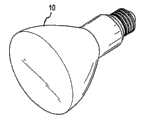
图1为商业标准的灯泡的等比例视图;Figure 1 is an isometric view of a commercial standard light bulb;
图2为根据本发明实施例的一种LED照明装置的等比例视图;Fig. 2 is an isometric view of an LED lighting device according to an embodiment of the present invention;
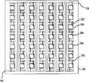
图3为根据本发明实施例的一种光学引擎的等比例视图,该光学引擎具有多个混联构成的表面安装式(surface-mounted)LED芯片;3 is an isometric view of an optical engine according to an embodiment of the present invention, the optical engine has a plurality of surface-mounted (surface-mounted) LED chips composed of parallel connections;
图4为根据本发明另一替换实施例的光学引擎的顶视图,该光学引擎具有多个混联构成的引线接合(wire-bonded)的LED芯片,其中每个LED芯片包括两个接合焊盘;4 is a top view of an optical engine having a plurality of wire-bonded LED chips in parallel configuration, wherein each LED chip includes two bonding pads, according to another alternative embodiment of the present invention. ;
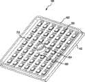
图5为根据本发明另一替换实施例的光学引擎的顶视图,该光学引擎具有多个串联构成的引线接合LED芯片;5 is a top view of an optical engine having a plurality of wire bonded LED chips configured in series according to another alternative embodiment of the present invention;
图6为根据本发明另一替换实施例的光学引擎的顶视图,该光学引擎具有多个混联构成的引线接合的LED芯片,其中每个LED芯片包括单个接合焊盘;6 is a top view of an optical engine having a plurality of wire-bonded LED chips in series, wherein each LED chip includes a single bond pad, in accordance with another alternative embodiment of the present invention;
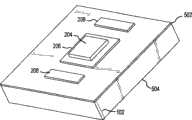
图7为示例性的光学引擎的等比例局部剖视图,该光学引擎包括一安装在金属覆层的,高导热性的PCB基底上的LED电路管芯;7 is an isometric partial cross-sectional view of an exemplary optical engine including an LED circuit die mounted on a metal clad, highly thermally conductive PCB substrate;
图8为包括有一内围堤和一外围堤的光学引擎的等比例视图;Figure 8 is an isometric view of an optical engine including an inner dike and an outer dike;
图9A和图9B分别示出光学引擎的顶视图和侧视图,该光学引擎包括填充有密封剂材料的外围堤和内围堤;9A and 9B show top and side views, respectively, of an optical engine comprising peripheral and inner dikes filled with encapsulant material;
图10为包括反射器和内围堤的光学引擎的等比例视图;Figure 10 is an isometric view of an optical engine including reflectors and inner dikes;
图11A和图11B分别为图10所示的光学引擎的顶视图和侧视图;11A and 11B are respectively a top view and a side view of the optical engine shown in FIG. 10;
图12A和图12B分别为包含有一示例性透镜的光学引擎的顶视图和侧视图;12A and 12B are top and side views, respectively, of an optical engine including an exemplary lens;
图13为表示不同温度白光的光谱的曲线图;以及Figure 13 is a graph showing the spectrum of white light at different temperatures; and
图14为根据本发明的一实施例,具有串联连接的LED芯片的电路图。14 is a circuit diagram with LED chips connected in series, according to an embodiment of the present invention.
具体实施方式Detailed ways
下文的描述仅是本发明示例性实施例的描述,并不以任何方式来限定本发明的范围、适用性或结构。相反,下文的描述欲为实现本发明的不同实施例提供方便的描述。显而易见,在不脱离本发明范围的情况下,这些实施例中描述的元件的功能和排列可作出多种变化。The following description is only a description of exemplary embodiments of the invention and is not intended to limit the scope, applicability, or structure of the invention in any way. Rather, the following description is intended to provide a convenient description for implementing various embodiments of the invention. It will be apparent that various changes may be made in the function and arrangement of elements described in these embodiments without departing from the scope of the invention.
概述overview
整体而言,根据本发明的LED照明装置包括提供所需输出电压的置于电路板上或独立的电源变换器(如,整流器)和具有高导热性基底(如,金属覆层的PCB)的光学引擎,机械地连接到该基底上的多个发光二极管(LED)半导体装置,固定在该基底上并且环绕该LED装置的至少一部分(优选地为全部)的外围堤,以及设置在多个LED装置上并由外围堤限制的基本上透明的聚合体密封剂(如,光学等级的硅树脂)。在一个实施例中,该光学引擎包括固定在基底上的反射器(如,一般的锥形反射器),以形成外围堤并帮助引导及聚焦光和/或来自两个或多个不同颜色的LED装置的光的混合。在其它实施例中,如下文进一步描述的,一个或多个光学元件如滤光片、透镜等等被固定在密封剂涂层上。In general, the LED lighting device according to the present invention includes a circuit board or independent power converter (such as a rectifier) and a substrate with high thermal conductivity (such as a metal clad PCB) to provide the required output voltage. an optical engine, a plurality of light emitting diode (LED) semiconductor devices mechanically connected to the substrate, a peripheral bank secured to the substrate and surrounding at least a portion (preferably all) of the LED devices, and a plurality of LED A substantially transparent polymeric encapsulant (eg, optical grade silicone) on the device and bounded by a peripheral dam. In one embodiment, the optical engine includes reflectors (e.g., generally conical reflectors) affixed to the substrate to form peripheral banks and help guide and focus light and/or light from two or more different colors. Mixing of light from LED devices. In other embodiments, as described further below, one or more optical elements such as filters, lenses, etc. are affixed to the encapsulant coating.
主体结构main structure
如上所述,根据本发明的不同方面,LED照明装置构造为替代商业标准灯泡,并通常包括主体20,光学引擎100,电连接器22(如,将LED照明装置连接至插座上的标准Edison式连接器)和各种其它元件。As noted above, according to various aspects of the present invention, LED lighting fixtures are configured to replace commercial standard light bulbs and generally include a main body 20, an
根据现在描述的实施例,主体20一般包括一个或多个元件,该元件容纳、保护和/或另外包含或带有LED照明装置的电源变换、光产生和电连接元件。在不同实施例中,主体20为具有适当刚度的固体材料,该材料具有适当的高导热性以消散来自LED照明装置的其它元件的热量。例如,诸如铝合金、铜合金黄铜、镁合金、碳聚合体、碳合成物的各种金属和/或陶瓷,高导热陶瓷在这方面具有所需特性。According to the presently described embodiment, the main body 20 generally includes one or more components that house, protect and/or otherwise contain or carry the power conversion, light generation and electrical connection components of the LED lighting device. In various embodiments, the body 20 is a solid material with suitable stiffness and high thermal conductivity to dissipate heat from other components of the LED lighting device. For example, various metals and/or ceramics such as aluminum alloys, copper alloys brass, magnesium alloys, carbon polymers, carbon composites, highly thermally conductive ceramics have desirable properties in this regard.
另外,在不同实施例中,主体20基本上可构造为任何形状,并有从连续的、基本“平滑”的表面到中断的不连续的表面(如,稽状物)的任何地方。此外,在各种应用和如下所述中,主体20可具有与商业标准灯泡相似的形状。Additionally, in various embodiments, body 20 may be configured in substantially any shape and have anywhere from a continuous, substantially "smooth" surface to interrupted, discontinuous surfaces (eg, ridges). Additionally, the body 20 may have a shape similar to a commercial standard light bulb in various applications and as described below.
尤其是,根据本发明的不同实施例,如上所述,LED照明装置欲代替和/或模拟商业标准灯泡。例如,商业标准灯泡,诸如图1所示的灯泡(如,BR30泛光灯泡),具有第一外表面轮廓10,通常限定其形状。在本发明的范围中,LED照明装置具有其自身的第二表面轮廓24,该轮廓基本上与商业标准灯泡的第一表面轮廓10相一致,并且同样的,在不同实施例中模拟或是近似模拟商业标准灯泡的尺寸和形状。应当理解,在本发明范围中,几乎可模拟或基本上模拟任何灯泡的形状,并且第二外表面轮廓基本上可构造为任何形状并仍落在本发明的范围之内。In particular, according to various embodiments of the present invention, as described above, LED lighting devices are intended to replace and/or simulate commercial standard light bulbs. For example, a commercial standard light bulb, such as the light bulb shown in FIG. 1 (eg, BR30 flood light bulb), has a first
如上所述,目前已知的商业上的大功率LED装置产生大量的能量(热能)。根据本发明不同实施例的LED照明装置还包括与LED照明装置的各种元件相连接的散热片以消散这种能量。通常,散热片包括任何通过传导和/或对流帮助热量消散的物理设备。根据不同实施例,散热片可为与LED照明装置分离的单独元件,或者可替换地,LED照明装置的其它元件除了该特定元件可具有的任何其它功能外还可作为散热片。As mentioned above, currently known commercial high power LED devices generate a large amount of energy (heat). LED lighting devices according to various embodiments of the present invention also include heat sinks connected to various components of the LED lighting device to dissipate such energy. In general, a heat sink includes any physical device that helps dissipate heat by conduction and/or convection. According to various embodiments, the heat sink may be a separate component from the LED lighting device, or alternatively, other components of the LED lighting device may act as a heat sink in addition to any other functions that particular component may have.
例如,根据本发明的不同实施例,主体20可作为散热片。在该实施例中,主体20可构造为便于热能消散的各种形状和尺寸,例如,通过增大主体20的表面积。例如,如图2中所示,主体20可构造为多个稽状物26,由此增加主体20的表面积,主体20因此可消散大量的热。For example, according to various embodiments of the present invention, the body 20 may act as a heat sink. In this embodiment, the body 20 can be configured in various shapes and sizes to facilitate dissipation of thermal energy, for example, by increasing the surface area of the body 20 . For example, as shown in FIG. 2, the body 20 may be configured as a plurality of ridges 26, thereby increasing the surface area of the body 20, and the body 20 may thus dissipate a substantial amount of heat.
另外,根据本发明的不同实施例。散热片还定义了第二外表面轮廓20。例如,继续参照图2,主体20和冷却稽状物26可用作散热片。各个稽状物26被这样构造以使外边缘28呈现商业标准灯泡的第一外表面轮廓10的横截面的一段。这样,例如在图2中多个稽状物26在LED照明装置的位置形成第二外表面轮廓20,该轮廓顺次基本上与商业标准灯泡相似,并且其还有作为散热片的好处。In addition, according to different embodiments of the present invention. The fins also define a second outer surface profile 20 . For example, with continued reference to FIG. 2 , the body 20 and cooling fins 26 may act as heat sinks. Each ridge 26 is configured such that the outer edge 28 presents a section of the cross-section of the first
LED连通性LED Connectivity
首先,参照示出了适于本发明的示例性电拓扑的图3,光学引擎100包括多个连接到高导热性基底(或简称为“基底”)102上的LED装置104(在本实施例中,表面安装式LED芯片)。在本实施例中,基底102包括与多个LED装置104电学或机械连接的导电轨迹图案106。First, referring to FIG. 3 which illustrates an exemplary electrical topology suitable for the present invention, an
轨迹图案106根据其应用被构造为与AC或DC电源相连接。例如,在所示的实施例中,提供DC V+端108和V。端110。在一些实例中,这些端在此一般称为“输入端”。The trace pattern 106 is configured to interface with an AC or DC power source depending on its application. For example, in the illustrated embodiment, a
LED装置104以任何适当的方式电学相互连接。如图3所示,例如,LED装置104可构造为电路以使多个装置组串联相接,其中这些组本身相对于输入端并联连接。在所示的实施例中,每列包括五个串联相接的LED装置的七个平行列本身并联连接于横跨端108和110。可替代地,暂时参考图5,多个LED装置104(在本实施例中,49个引线接合的芯片)于端110和108串联相接。LED devices 104 are electrically interconnected in any suitable manner. As shown in FIG. 3, for example, LED devices 104 may be configured as a circuit to connect groups of devices in series, where the groups themselves are connected in parallel with respect to the input. In the illustrated embodiment, seven parallel columns each comprising five LED devices connected in series are themselves connected in parallel across
通常,尽管上述所示的实施例,本发明包括使用构造为任何适合电拓扑(串联、并联或它们的结合)和任何合适的几何形状的任何数目的LED装置。例如,该LED装置可定位在直线形图案(例如,正方形或矩形阵列)、圆形或曲线图案、任意或随机图案,或它们的任意组合图案中。另外,LED装置可设置在多个区域中,其中每个区域具有不同的图案和数量的装置。In general, notwithstanding the embodiments shown above, the present invention encompasses the use of any number of LED devices configured in any suitable electrical topology (series, parallel or combinations thereof) and in any suitable geometry. For example, the LED devices can be positioned in a rectilinear pattern (eg, a square or rectangular array), a circular or curved pattern, a random or random pattern, or any combination thereof. Additionally, LED devices may be provided in multiple zones, with each zone having a different pattern and number of devices.
引入到装置中的LED装置104的数量可根据多个设计变量选择,例如包括电源的性质(AC转换为DC,有效DC电压,有效功率等),该LED装置自身的性质(如,正向电压(Vf),额定功率,发光强度,波长等),所需的颜色混合(下文描述),基底102的性质(如,导热性,几何形状等),以及应用和外部热条件的性质。The number of LED devices 104 incorporated into the device can be selected based on a number of design variables including, for example, the nature of the power source (AC to DC conversion, effective DC voltage, effective power, etc.), the properties of the LED device itself (e.g., forward voltage (Vf , power rating, luminous intensity, wavelength, etc.), desired color mixing (described below), properties of the substrate 102 (eg, thermal conductivity, geometry, etc.), and properties of the application and external thermal conditions.
简言之,在被输入至LED组之前,所施加的电压通常必须在由所使用的特定LED的功率所指定的范围内。同样,根据本发明的不同实施例,LED照明装置包括电源转换器,该电源转换器根据其构造可升高电压、降低电压和/或将AC转换为DC。例如,在不同实施例中,电源转换器包括整流器,例如与多个LED电连接的桥接电路,与图14中所示的类似,其中LED(1402)与电源转换器104及电源1406耦合。优选地,电源转换器1404在LED照明装置和/或主体20中是完全独立的。In short, the applied voltage must generally be within the range specified by the power of the particular LED being used before being input to the LED group. Also, according to various embodiments of the present invention, an LED lighting device includes a power converter that, depending on its configuration, can step up voltage, step down voltage, and/or convert AC to DC. For example, in various embodiments, the power converter includes a rectifier, such as a bridge circuit, electrically connected to a plurality of LEDs, similar to that shown in FIG. 14 , where LEDs (1402) are coupled to power converter 104 and power source 1406. Preferably, the power converter 1404 is completely independent in the LED lighting device and/or the main body 20 .
也就是说,在一个实施例中,该LED装置串联或并联连接以使LED装置的全部联合正电压与电输入匹配。例如,在美国和加拿大的家庭应用中,在输入至LED之前,120V AC必须由电源转换器整流为162V DC。一般来说,根据各个LED的Vf,40至80只LED装置可串行连接,以接受162V整流过的DC输入。众所周知,典型的红和琥珀色的LED装置的额定Vf约为1.8至2.5V,绿和蓝色LED的额定Vf约为3.0至4.5V。That is, in one embodiment, the LED devices are connected in series or in parallel such that all combined positive voltages of the LED devices match the electrical input. For example, in domestic applications in the US and Canada, 120V AC must be rectified to 162V DC by a power converter before input to the LEDs. Typically, 40 to 80 LED devices can be connected in series to accept a rectified 162V DC input, depending on theVf of each LED. It is known that typical red and amber LED devices have a ratedVf of about 1.8 to 2.5V, and green and blue LEDs have a ratedVf of about 3.0 to 4.5V.
通过使联合正电压和输入电源的电压相匹配,可简化光学引擎的电源提供,不需要大体积、复杂的电压升高或降低的整流器,或是切换电源供给来与系统连接;简单、有效的AC转换为DC的整流电路就足够了。这就使得光学引擎被结合到结构紧凑的组件中-例如,适于标准灯泡插座的灯泡组件。By matching the combined positive voltage to the voltage of the input power supply, the power supply of the optical engine can be simplified, and there is no need for bulky, complex voltage step-up or step-down rectifiers, or switching power supplies to interface with the system; simple, effective A rectifier circuit that converts AC to DC is sufficient. This allows the optical engine to be incorporated into a compact assembly - for example, a light bulb assembly that fits into a standard light bulb socket.
LED装置LED device
任何适合种类的LED装置104可用于与本发明连接,包括单独管芯,芯片级封装,传统封装,表面安装式装置(SMD),或是任何其它现在已知的或是未来发展的LED装置。在结合图3描述的实施例中,例如,LED装置104包括具有电连接的表面安装式装置,该表面安装式装置具有直接安装到轨迹图案106的表面上的电接点,例如,“倒装晶片(flip-chip)”或是焊料凸起的管芯上。Any suitable type of LED device 104 may be used in connection with the present invention, including individual dies, chip scale packages, conventional packages, surface mount devices (SMD), or any other now known or future developed LED devices. In the embodiment described in connection with FIG. 3, for example, the LED device 104 comprises a surface mount device with electrical connections having electrical contacts mounted directly to the surface of the trace pattern 106, such as a "flip chip (flip-chip)” or solder bumped die.
现参照图4和图5,作为选择,该LED装置可包括连接到各自PCB衬垫206上的LED芯片204(经过热导环氧接合剂等),其中每个管芯204具有至少两个焊盘,用于经过引线接合互连202而提供电连接。可选地,中间的PCB衬垫208可用于方便各个管芯之间的引线接合。该实施例示出七组平行的七个管芯串联;然而,如上所述,本发明不限于此,而可包括任何数目的管芯串联连接、并联连接或是混合连接。Referring now to FIGS. 4 and 5 , as an option, the LED device may include
图7描述了图4和图5中所示的单个LED装置的等比例局部剖视图。如图所示,基底102包括其上覆盖有高导热性、电绝缘材料502的高导热性底座504。各个PCB轨迹208和206置于层502上,并且LED管芯204接合至PCB轨迹206上。引线接合(未示出)用于使管芯204和邻近的电管芯相互连接(例如,利用中间PCB轨迹208)。FIG. 7 depicts an isometric partial cross-sectional view of a single LED device shown in FIGS. 4 and 5 . As shown,
图6还示出了本发明的另一实施例。根据这种设计,各个LED电路管芯204被接合(经过焊料接合或是其它导电连接)到PCB衬垫206上。然后各个引线接合202用于将PCB衬垫206连接至邻近管芯的接合区域上。也就是说,每个LED管芯204包括单个焊盘,该管芯的背面用作第二电路连接。Fig. 6 also shows another embodiment of the present invention. According to this design, individual LED circuit dies 204 are bonded (via solder bonds or other conductive connections) to
利用一个或多个适当的半导体材料制造LED装置104,例如,包括GaAsP、GaP、AlGaAs AlGaInP、GaInN等。选定的该LED装置104的尺寸可使用不同的设计参数来确定。在一个实施例中,LED装置104是厚约100微米、750×750平方微米的管芯。本领域的技术人员将会认识到本发明并不限于此。LED device 104 is fabricated using one or more suitable semiconductor materials, including, for example, GaAsP, GaP, AlGaAs, AlGaInP, GaInN, and the like. The selected dimensions of the LED device 104 can be determined using various design parameters. In one embodiment, LED device 104 is a die approximately 100 microns thick, 750 x 750 microns square. Those skilled in the art will recognize that the present invention is not so limited.
各个LED装置具有对应于特定波长(或频率)的特定颜色。本发明的不同方面涉及不同的光选择,现在和下文将讨论增强和平滑的机械装置和/或技术。例如,不同颜色的多个LED产生发射光的所需颜色。通常,安装在基底上的一组LED装置包括x只红LED、y只绿LED和z只蓝LED,其中选定x∶y∶z比例以获得特定相关色温(CCT)的白光。Each LED device has a specific color corresponding to a specific wavelength (or frequency). Different aspects of the invention relate to different light selections, enhancing and smoothing mechanisms and/or techniques are discussed now and below. For example, multiple LEDs of different colors produce the desired color of emitted light. Typically, a set of LED devices mounted on a substrate includes x red LEDs, y green LEDs and z blue LEDs, where the ratio x:y:z is selected to obtain white light at a specific correlated color temperature (CCT).
通常,任意数量的LED颜色可以以任意所需的比例使用。典型的白炽灯泡产生具有2700K CCT的光(暖白光),荧光灯泡产生约5000K CCT的光。这样,典型地将需更多的红和黄LED以获得2700K的光,而对于5000K的光则需更多的蓝LED。为了获得高彩色再现指数(CRI,Color Rendering Index),光源必须发射具有几乎覆盖可见光全部范围(308nm至770nm波长)的光谱的白光,以使在混合中出现暗红、淡红、琥珀色、淡绿、暗绿、淡蓝和深蓝颜色。In general, any number of LED colors can be used in any desired ratio. A typical incandescent bulb produces light with a CCT of 2700K (warm white light), and a fluorescent bulb produces light with a CCT of about 5000K. Thus, typically more red and yellow LEDs will be required for 2700K light, and more blue LEDs for 5000K light. In order to obtain a high color rendering index (CRI, Color Rendering Index), the light source must emit white light with a spectrum covering almost the entire range of visible light (308nm to 770nm wavelength), so that dark red, light red, amber, light Green, dark green, light blue and dark blue colors.
为了达到这些目的,本发明允许具有不同波长的LED装置被包含到光学引擎中。在一个实施例中,例如,为了获得3200K的光,R(620nm)∶Y(590nm)∶G(525nm)∶B(465nm)的混合比例(相对于LED的数目)为6∶2∶5∶1。根据另一实施例,R∶Y∶G∶B的混合比例为7∶3∶7∶2,用于获得3900K的光。在另一实施例中,10∶3∶10∶4的比例用于获得5000K的光。上述三个实施例中的每个的光谱示于图13中。To achieve these objectives, the present invention allows LED devices with different wavelengths to be incorporated into the optical engine. In one embodiment, for example, to obtain light at 3200K, the mixing ratio (relative to the number of LEDs) of R(620nm):Y(590nm):G(525nm):B(465nm) is 6:2:5: 1. According to another embodiment, the mixing ratio of R:Y:G:B is 7:3:7:2 for obtaining 3900K light. In another embodiment, a ratio of 10:3:10:4 is used to obtain 5000K light. The spectra of each of the above three examples are shown in FIG. 13 .
将会意识到,列举的混合比例由芯片的强度以及它们的波长决定。因此,本发明不局限于可用于形成所需光输出的LED种类的数量。It will be appreciated that the mixing ratios listed are determined by the intensities of the chips as well as their wavelengths. Thus, the present invention is not limited by the number of LED species that can be used to create a desired light output.
除了白光之外,本发明还可利用类似的颜色混合技术产生特定颜色的光。即,虽然经常可利用多个单色LED产生所需的颜色,但在某些实例中也可利用两种或多种颜色的LED组合形成复合颜色。In addition to white light, the present invention can also use similar color mixing techniques to generate light of a specific color. That is, while multiple single color LEDs can often be utilized to produce a desired color, in some instances LEDs of two or more colors can be combined to form a composite color.
更具体的说,由于LED化合物半导体的材料特性,某些波长的功效是不期望的。例如,没有传统的化合物半导体材料可有效发射575nm的黄光。该波长(575nm)位于AlGaInP和GaInN半导体之间的性能谷。然而,通过混合由这两种材料制造的LED装置,可产生具有所需功效的黄光。More specifically, due to the material properties of LED compound semiconductors, efficacy at certain wavelengths is undesirable. For example, no conventional compound semiconductor material efficiently emits yellow light at 575nm. This wavelength (575nm) is located in the performance valley between AlGaInP and GaInN semiconductors. However, by mixing LED devices made from these two materials, it is possible to produce yellow light with the desired efficacy.
基底base
基底102包括能够提供机械支撑LED装置104或LED管芯204的任意结构,该结构同时提供所需的热特性-即,通过帮助消散由LED装置104或LED管芯204产生的全部或部分热量。在这一点上,基底102优选包括高导热性基底。
此处所使用的术语“高导热性基底”是指其有效导热率大于1W/°K-m,优选大于约3W/°K-m的基底。因此该基底102的几何形状和材料可根据其应用变化。在一个实施例中,基底102包括一金属包覆的PCB,例如,ThermagonT-Lam或是Bergquist热包覆基底。可利用传统的FR-4PCB工艺制造该金属包覆PCB,并因此相对有成本效益。其它适合的基底包括各种混合陶瓷基底和搪瓷金属基底。另外,通过在基底上应用白色掩模以及使轨迹电路镀银,可增强来自基底的光反射。As used herein, the term "high thermal conductivity substrate" refers to a substrate having an effective thermal conductivity greater than 1 W/°K-m, preferably greater than about 3 W/°K-m. The geometry and material of the
密封剂层sealant layer
优选地,基本上透明的聚合物密封剂设置在LED装置上,然后适当地固化以提供保护层。在优选实施例中,该密封剂包括光学等级的硅树脂。可选择该密封剂的特性以获得其它的光学特性,例如,通过滤除由LED装置产生的光。与此同时,该保护密封剂层足够柔软以抵挡组件承受的热漂移,而不使管芯、引线接合和其它元件老化。Preferably, a substantially transparent polymeric encapsulant is disposed over the LED device and then suitably cured to provide a protective layer. In a preferred embodiment, the encapsulant comprises optical grade silicone. The properties of the encapsulant can be selected to obtain other optical properties, for example, by filtering out light generated by the LED device. At the same time, the protective encapsulant layer is flexible enough to withstand thermal excursions experienced by the component without degrading the die, wire bonds, and other components.
图8、9A和图9B表示本发明一实施例的不同视图,其中覆盖LED装置的密封剂适于由围堤结构限定。更具体的说,图8的光学引擎100包括一外围堤602,其环绕LED管芯204的至少一部分。在优选实施例中,围堤602通常为环绕整个LED管芯204的阵列的矩形、正方形、六边形、圆形、八边形或是椭圆结构。外围堤602适于利用粘合剂或是其它所需的连接方法连接到基底102上。由于光学的原因优选圆形围堤。Figures 8, 9A and 9B show different views of an embodiment of the invention wherein the encapsulant covering the LED device is adapted to be defined by a dike structure. More specifically, the
如图所示,密封剂材料优选地沉积在LED管芯204上,以使其填满由外围堤602限定的空间。也就是说,参照图9B所示的横截面(截面A-A),密封剂材料606填充到外围堤602的上表面上。另外,外围堤602优选由基本上透明的材料成,例如,透明塑料(例如,聚碳酸酯)材料。其透明度允许围绕光学引擎边缘的光发射。As shown, the encapsulant material is preferably deposited on the LED die 204 such that it fills the space defined by the
在可选择的实施例中,第二、内围堤604位于LED管芯204的中心附近。内围堤604的作用是限制密封剂,并优选为透明材料。内围堤604的出现允许通过电路板中心的连接。In an alternative embodiment, the second,
反射器reflector
根据本发明的另一实施例,LED装置还包括反射器32,其构造为帮助聚焦和/或引导由光学引擎100产生的光。例如,根据一个示例性实施例,反射器32通常为圆锥形。当然,本领域的技术人员应认识到,根据所需的结果和效应可在本发明范围中使用多种形状反射器32的。例如,反射器32可为抛物线形、角形或其它所需的形状和尺寸。另外,通常需要反射器32的结构和材料为高反射。这样,在该实施例中,反射器32优选地通常为平滑的、抛光的、镜面状内表面。According to another embodiment of the present invention, the LED device further includes a reflector 32 configured to help focus and/or direct the light generated by the
然而,在LED装置的应用中,其中基本上以白光(或其它特定颜色)作为目标,并且两个或多个颜色的LED用于混合产生该颜色,优选反射器32的内表面起到散射由LED装置产生的光的作用,从而提供最佳的颜色混合,即使光学引擎的效率或聚焦会因此而稍微地降低(由于光散射)。例如,在本发明的一些实施例中,其中使用两个或多个LED颜色,该反射器32的内表面由“构造表面的质地”的现在已知的或还未知的工艺来构成。在这一点上,该反射器32可为小刻面的、喷砂处理的、化学方法使表面粗糙的,或另外其质地被构造来提供所需散射率。另外,质地或小刻面可为任意的、有规律的、随机的或是它们的结合。However, in LED device applications where essentially white light (or other specific color) is targeted and two or more colored LEDs are used to mix to produce that color, it is preferred that the inner surface of reflector 32 acts to scatter light from the The action of the light produced by the LED device, thus providing the best color mixing, even though the efficiency or focus of the optical engine will be slightly reduced (due to light scattering) as a result. For example, in some embodiments of the invention in which two or more LED colors are used, the inner surface of the reflector 32 is constructed by a now known or as yet unknown process of "texturing the surface". In this regard, the reflector 32 may be faceted, sandblasted, chemically roughened, or otherwise textured to provide the desired scattering rate. Additionally, the texture or facets can be random, regular, random or a combination thereof.
在另一实施例中,光学引擎包括反射器环,其基本上环绕LED装置并帮助聚焦和/或引导系统产生的光。In another embodiment, the optical engine includes a reflector ring that substantially surrounds the LED device and helps focus and/or direct light generated by the system.
参照图10,示例性的反射器802以所有的LED管芯204都位于反射器底座上的方式合适地连接到光学引擎的基底102上。在所示的实施例中,反射器802通常为圆锥形。然而,将会认识到,反射器802可为抛物面形、角形或具有任何其它所需的形状和尺寸。如所示出的,反射器802通过限制密封剂起到外围堤的作用。Referring to FIG. 10, an
就反射器802被设计用来引导和聚焦LED管芯204产生的光来说,需要反射器802的质地和材料具有高反射率。在这一点上,反射器802优选地通常具有平滑的、抛光的、镜面状的内表面。To the
在基本上以白光(或其它特定颜色)作为目标,并且LED的两个或多个颜色用于混合产生该颜色的应用中,优选的是反射器802的内表面起到散射由LED装置产生的光的作用,从而提供最佳的颜色混合,即使光学引擎的效率或聚焦会因此而稍微地降低(由于光散射)。因此,在使用两个或多个LED颜色的应用中,该反射器802的内表面优选通过适当的工艺并以适当的比例构造质地。例如,该反射器802可为小刻面的、喷砂处理的、化学方法使表面粗糙的,或另外质地被构造来提供所需散射率。另外,质地或小刻面可为任意的、有规律的、随机的或是它们的结合。In applications where essentially white light (or other specific color) is targeted, and two or more colors of LEDs are used to mix to produce that color, it is preferred that the inner surface of
其它光学元件other optical components
根据本发明的另一实施例,该LED装置包括用于保护光学引擎100的透镜30。例如,如图2所示,透镜30贴近环绕光学引擎100的中空部分。根据不同实施例,该透镜30由硬质玻璃、塑料(如,聚碳酸酯)或相似的材料构成,该材料有助于防止光学引擎100受到损害,但仍允许光经过。更优选的是,透镜30由光学品质的材料构成。According to another embodiment of the present invention, the LED device includes a lens 30 for protecting the
根据本发明的另一实施例,具有一个或多个光学元件的集成光学引擎设置在密封剂的表面上,以相对于由LED装置发射的光提供所需的光学效应。这些光学元件本身可为硬质玻璃或是塑料,当密封剂层作为保护表面时,不引起对LED装置的损坏。适当的光学元件包括,例如,各种透镜(凹透镜、凸透镜、平面透镜、“泡状(bubble)”透镜、菲涅尔透镜等等)以及各种滤光片(偏振滤光片、彩色滤光片等)。According to another embodiment of the present invention, an integrated optical engine having one or more optical elements is disposed on the surface of the encapsulant to provide the desired optical effect with respect to the light emitted by the LED device. These optics themselves can be hard glass or plastic, which does not cause damage to the LED device while the encapsulant layer acts as a protective surface. Suitable optical elements include, for example, various lenses (concave, convex, planar, "bubble" lenses, Fresnel lenses, etc.) and various filters (polarizing filters, color filters film, etc.).
根据本发明的另一实施例,一个或多个光学元件设置在密封剂的表面上,以相对于由LED装置发射的光提供所需的光学效应。这些光学元件本身可为硬质玻璃或是塑料,当密封剂层作为保护表面时,不引起对LED装置的损坏。适当的光学元件包括,例如,各种透镜(凹透镜、凸透镜、平面透镜、“泡状(bubble)”透镜、菲涅尔透镜等等)以及各种滤光片(偏振滤光片、彩色滤光片等)。According to another embodiment of the present invention, one or more optical elements are arranged on the surface of the encapsulant to provide a desired optical effect with respect to the light emitted by the LED device. These optics themselves can be hard glass or plastic, which does not cause damage to the LED device while the encapsulant layer acts as a protective surface. Suitable optical elements include, for example, various lenses (concave, convex, planar, "bubble" lenses, Fresnel lenses, etc.) and various filters (polarizing filters, color filters film, etc.).
图12A、12B和12C示出根据本发明的一个实施例的光学引擎的顶视图、剖面图和等比例视图,其中光学引擎含有“泡状”透镜。更多的泡状透镜102包括与密封剂606连接的平面侧,并且泡状侧包括多个凸起区域1004。在所示的实施例中,泡状透镜102包括4×4格子的这种泡状凸起。本发明认真考虑了这种透镜特征的任何数目和尺寸。Figures 12A, 12B and 12C show top, cross-sectional and isometric views of an optical engine containing a "bubble" lens according to one embodiment of the present invention. More lens bubbles 102 include a planar side connected to encapsulant 606 , and the bubble side includes a plurality of raised regions 1004 . In the illustrated embodiment, the
结论in conclusion
简言之,本发明提供一种新型的、高效的板上多芯片LED光学引擎,该光学引擎能够用于任何现在已知的或未来发展的可以想象的照明应用中。例如,这样的光学引擎可用于要求灯泡安装到标准家用装置(标准螺旋灯泡、荧光灯、卤素灯等)的应用,汽车应用(尾灯、头灯、闪光信号灯等等),便携照明应用和交通控制应用(交通信号等)中。另外,所请求保护的光学引擎可用于要求特定颜色或颜色范围的应用中,包括任意所需色温的白光。在本申请中没有什么欲限定其中可使用本发明的应用的范围。In short, the present invention provides a novel, highly efficient multi-chip LED on board optical engine that can be used in any imaginable lighting application, now known or developed in the future. For example, such an optical engine can be used in applications that require light bulbs to fit into standard household fixtures (standard screw bulbs, fluorescent lights, halogen lights, etc.), automotive applications (taillights, headlights, blinkers, etc.), portable lighting applications, and traffic control applications (traffic signal, etc.). Additionally, the claimed optical engine can be used in applications requiring a specific color or range of colors, including white light at any desired color temperature. Nothing in this application is intended to limit the scope of applications in which the invention may be used.
本发明其它的优点和结构上的细节从所附的图中显而易见,本领域的技术人员会很好的理解。上面已根据特定的示例性实施例描述了本发明。然而,在不背离本发明的范围下可对示例性实施例作出许多改变、结合和变形。Other advantages and structural details of the present invention are apparent from the accompanying drawings and will be well understood by those skilled in the art. The invention has been described above in terms of specific exemplary embodiments. However, many changes, combinations and modifications may be made to the exemplary embodiments without departing from the scope of the present invention.
相关申请的交叉参考Cross References to Related Applications
本申请要求2003年10月1日递交的美国临时专利申请第60/507,858号、2004年1月30日递交的美国临时专利申请第60/540,743号和2004年8月23日递交的美国临时专利申请第(TBD)号的优选权,这些文件在此全文引作参考。This application claims U.S. Provisional Patent Application No. 60/507,858, filed October 1, 2003, U.S. Provisional Patent Application No. 60/540,743, filed January 30, 2004, and U.S. Provisional Patent Application No. 60/540,743, filed August 23, 2004 Priority to Application No. (TBD), which documents are hereby incorporated by reference in their entirety.
Claims (3)
Applications Claiming Priority (6)
| Application Number | Priority Date | Filing Date | Title |
|---|---|---|---|
| US50785803P | 2003-10-01 | 2003-10-01 | |
| US60/507858 | 2003-10-01 | ||
| US54074304P | 2004-01-30 | 2004-01-30 | |
| US60/540743 | 2004-01-30 | ||
| US10/924,389US6942360B2 (en) | 2003-10-01 | 2004-08-23 | Methods and apparatus for an LED light engine |
| US10/924389 | 2004-08-23 |
Publications (2)
| Publication Number | Publication Date |
|---|---|
| CN1605790A CN1605790A (en) | 2005-04-13 |
| CN1605790Btrue CN1605790B (en) | 2011-01-05 |
Family
ID=34397030
Family Applications (1)
| Application Number | Title | Priority Date | Filing Date |
|---|---|---|---|
| CN2004100903315AExpired - Fee RelatedCN1605790B (en) | 2003-10-01 | 2004-09-30 | LED light apparatus and method therefor |
Country Status (6)
| Country | Link |
|---|---|
| US (2) | US6942360B2 (en) |
| JP (1) | JP2007507115A (en) |
| KR (1) | KR20060066742A (en) |
| CN (1) | CN1605790B (en) |
| TW (1) | TWI245103B (en) |
| WO (1) | WO2005034198A2 (en) |
Families Citing this family (206)
| Publication number | Priority date | Publication date | Assignee | Title |
|---|---|---|---|---|
| US6942360B2 (en)* | 2003-10-01 | 2005-09-13 | Enertron, Inc. | Methods and apparatus for an LED light engine |
| US7824065B2 (en)* | 2004-03-18 | 2010-11-02 | Lighting Science Group Corporation | System and method for providing multi-functional lighting using high-efficiency lighting elements in an environment |
| US7114841B2 (en)* | 2004-03-22 | 2006-10-03 | Gelcore Llc | Parallel/series LED strip |
| US7215086B2 (en) | 2004-04-23 | 2007-05-08 | Lighting Science Group Corporation | Electronic light generating element light bulb |
| US7367692B2 (en)* | 2004-04-30 | 2008-05-06 | Lighting Science Group Corporation | Light bulb having surfaces for reflecting light produced by electronic light generating sources |
| US20060126346A1 (en)* | 2004-12-10 | 2006-06-15 | Paul R. Mighetto | Apparatus for providing light |
| US7387403B2 (en)* | 2004-12-10 | 2008-06-17 | Paul R. Mighetto | Modular lighting apparatus |
| US9070850B2 (en) | 2007-10-31 | 2015-06-30 | Cree, Inc. | Light emitting diode package and method for fabricating same |
| US9793247B2 (en)* | 2005-01-10 | 2017-10-17 | Cree, Inc. | Solid state lighting component |
| US20060171157A1 (en)* | 2005-01-31 | 2006-08-03 | Karras Steve A | Glowrims |
| JP4583956B2 (en)* | 2005-02-10 | 2010-11-17 | Necライティング株式会社 | Manufacturing method of planar light source device |
| JP5059739B2 (en)* | 2005-03-11 | 2012-10-31 | ソウル セミコンダクター カンパニー リミテッド | Light emitting diode package having an array of light emitting cells connected in series |
| CA2617314A1 (en)* | 2005-04-05 | 2006-10-12 | Tir Technology Lp | Mounting assembly for optoelectronic devices |
| US7758223B2 (en)* | 2005-04-08 | 2010-07-20 | Toshiba Lighting & Technology Corporation | Lamp having outer shell to radiate heat of light source |
| US7633177B2 (en)* | 2005-04-14 | 2009-12-15 | Natural Forces, Llc | Reduced friction wind turbine apparatus and method |
| US8272757B1 (en)* | 2005-06-03 | 2012-09-25 | Ac Led Lighting, L.L.C. | Light emitting diode lamp capable of high AC/DC voltage operation |
| US20060290891A1 (en)* | 2005-06-23 | 2006-12-28 | Augux Co., Ltd. | Device for cooling light emitting diode projector |
| JP2007036073A (en)* | 2005-07-29 | 2007-02-08 | Hitachi Displays Ltd | LIGHTING DEVICE AND DISPLAY DEVICE USING THE LIGHTING DEVICE |
| US8901575B2 (en) | 2005-08-09 | 2014-12-02 | Seoul Viosys Co., Ltd. | AC light emitting diode and method for fabricating the same |
| US8163580B2 (en) | 2005-08-10 | 2012-04-24 | Philips Lumileds Lighting Company Llc | Multiple die LED and lens optical system |
| US7518236B2 (en)* | 2005-10-26 | 2009-04-14 | General Electric Company | Power circuit package and fabrication method |
| US7573073B2 (en)* | 2005-11-22 | 2009-08-11 | 3M Innovative Properties Company | Arrays of light emitting articles and method of manufacturing same |
| TWM291088U (en)* | 2005-12-08 | 2006-05-21 | Upec Electronics Corp | Illuminating device |
| US7772604B2 (en) | 2006-01-05 | 2010-08-10 | Illumitex | Separate optical device for directing light from an LED |
| US7488097B2 (en)* | 2006-02-21 | 2009-02-10 | Cml Innovative Technologies, Inc. | LED lamp module |
| US9346397B2 (en) | 2006-02-22 | 2016-05-24 | Federal Signal Corporation | Self-powered light bar |
| US9002313B2 (en) | 2006-02-22 | 2015-04-07 | Federal Signal Corporation | Fully integrated light bar |
| US7476013B2 (en) | 2006-03-31 | 2009-01-13 | Federal Signal Corporation | Light bar and method for making |
| US7746794B2 (en) | 2006-02-22 | 2010-06-29 | Federal Signal Corporation | Integrated municipal management console |
| US20070211866A1 (en)* | 2006-02-22 | 2007-09-13 | Federal Signal Corporation | Public safety warning network |
| US7784969B2 (en)* | 2006-04-12 | 2010-08-31 | Bhc Interim Funding Iii, L.P. | LED based light engine |
| US7863639B2 (en)* | 2006-04-12 | 2011-01-04 | Semileds Optoelectronics Co. Ltd. | Light-emitting diode lamp with low thermal resistance |
| US8373195B2 (en) | 2006-04-12 | 2013-02-12 | SemiLEDs Optoelectronics Co., Ltd. | Light-emitting diode lamp with low thermal resistance |
| US9335006B2 (en) | 2006-04-18 | 2016-05-10 | Cree, Inc. | Saturated yellow phosphor converted LED and blue converted red LED |
| CN101449391B (en)* | 2006-05-30 | 2011-02-23 | 株式会社藤仓 | A base plate for mounting a luminous element, a light source, a lighting device, a display device, a piece of traffic signalling equipment and a manufacturing method of the base plate for mounting the |
| US7909482B2 (en) | 2006-08-21 | 2011-03-22 | Innotec Corporation | Electrical device having boardless electrical component mounting arrangement |
| US20080074884A1 (en)* | 2006-09-25 | 2008-03-27 | Thye Linn Mok | Compact high-intensty LED-based light source and method for making the same |
| US20090275157A1 (en)* | 2006-10-02 | 2009-11-05 | Illumitex, Inc. | Optical device shaping |
| WO2008042351A2 (en) | 2006-10-02 | 2008-04-10 | Illumitex, Inc. | Led system and method |
| US10295147B2 (en) | 2006-11-09 | 2019-05-21 | Cree, Inc. | LED array and method for fabricating same |
| US8026115B2 (en)* | 2006-11-17 | 2011-09-27 | 3M Innovative Properties Company | Optical bonding composition for LED light source |
| WO2008064068A2 (en)* | 2006-11-17 | 2008-05-29 | 3M Innovative Properties Company | Planarized led with optical extractor |
| JP4561732B2 (en)* | 2006-11-20 | 2010-10-13 | トヨタ自動車株式会社 | Mobile positioning device |
| WO2008063884A1 (en)* | 2006-11-20 | 2008-05-29 | 3M Innovative Properties Company | Optical bonding composition for led light source |
| US7701055B2 (en)* | 2006-11-24 | 2010-04-20 | Hong Applied Science And Technology Research Institute Company Limited | Light emitter assembly |
| US20080123340A1 (en)* | 2006-11-27 | 2008-05-29 | Mcclellan Thomas | Light device having LED illumination and electronic circuit board in an enclosure |
| US20080122364A1 (en)* | 2006-11-27 | 2008-05-29 | Mcclellan Thomas | Light device having LED illumination and an electronic circuit board |
| JP2010512662A (en) | 2006-12-11 | 2010-04-22 | ザ リージェンツ オブ ザ ユニバーシティ オブ カリフォルニア | Transparent light emitting diode |
| CN101210664A (en)* | 2006-12-29 | 2008-07-02 | 富准精密工业(深圳)有限公司 | Light-emitting diode lamps and lanterns |
| TWI342075B (en)* | 2007-01-08 | 2011-05-11 | Ledtech Electronics Corp | Ceramic package for led |
| CN101067479A (en)* | 2007-02-06 | 2007-11-07 | 宁波安迪光电科技有限公司 | Large power LED illuminating device |
| JP4753904B2 (en) | 2007-03-15 | 2011-08-24 | シャープ株式会社 | Light emitting device |
| US8408773B2 (en) | 2007-03-19 | 2013-04-02 | Innotec Corporation | Light for vehicles |
| US7712933B2 (en) | 2007-03-19 | 2010-05-11 | Interlum, Llc | Light for vehicles |
| US7918596B2 (en)* | 2007-04-20 | 2011-04-05 | Federal Signal Corporation | Warning light |
| US20080258900A1 (en)* | 2007-04-20 | 2008-10-23 | George Frank | Warning light |
| US7566147B2 (en)* | 2007-05-04 | 2009-07-28 | Ruud Lighting, Inc. | Multi-LED light fixture with secure arrangement for LED-array wiring |
| US7651245B2 (en) | 2007-06-13 | 2010-01-26 | Electraled, Inc. | LED light fixture with internal power supply |
| US20090279278A1 (en)* | 2007-08-03 | 2009-11-12 | Rohm Co., Ltd. | Light emitting device and method for manufacturing the same |
| CN101377292B (en)* | 2007-08-27 | 2010-09-29 | 宏齐科技股份有限公司 | Light-emitting diode lamp structure and system with high-efficiency heat dissipation function |
| US8240871B2 (en)* | 2007-09-27 | 2012-08-14 | Enertron, Inc. | Method and apparatus for thermally effective removable trim for light fixture |
| US7670021B2 (en)* | 2007-09-27 | 2010-03-02 | Enertron, Inc. | Method and apparatus for thermally effective trim for light fixture |
| CN100554764C (en)* | 2007-09-29 | 2009-10-28 | 四川新力光源有限公司 | Flush type LED lamp |
| JP4569683B2 (en) | 2007-10-16 | 2010-10-27 | 東芝ライテック株式会社 | Light emitting element lamp and lighting apparatus |
| US9086213B2 (en)* | 2007-10-17 | 2015-07-21 | Xicato, Inc. | Illumination device with light emitting diodes |
| US8018139B2 (en)* | 2007-11-05 | 2011-09-13 | Enertron, Inc. | Light source and method of controlling light spectrum of an LED light engine |
| TW200924229A (en)* | 2007-11-23 | 2009-06-01 | Gigno Technology Co Ltd | LED package module and manufacturing method thereof |
| CN101451698A (en)* | 2007-11-30 | 2009-06-10 | 上海三思电子工程有限公司 | High power LED light source unit for lighting integrated with heat radiator |
| WO2009076579A2 (en) | 2007-12-12 | 2009-06-18 | Innotec Corporation | Overmolded circuit board and method |
| US7655954B2 (en)* | 2007-12-17 | 2010-02-02 | Ledtech Electronics Corp. | Array type light-emitting device with high color rendering index |
| CN101910875B (en)* | 2007-12-24 | 2016-06-15 | 可隆工业株式会社 | Optical module |
| JP5353216B2 (en)* | 2008-01-07 | 2013-11-27 | 東芝ライテック株式会社 | LED bulb and lighting fixture |
| US7815339B2 (en) | 2008-01-09 | 2010-10-19 | Innotec Corporation | Light module |
| JP2011512037A (en) | 2008-02-08 | 2011-04-14 | イルミテックス, インコーポレイテッド | System and method for emitter layer shaping |
| TW200937668A (en)* | 2008-02-20 | 2009-09-01 | Harvatek Corp | LED chip package structure with different LED arrangement spacing and its packaging method |
| TW200939869A (en)* | 2008-03-05 | 2009-09-16 | Harvatek Corp | An LED chip package structure with a high-efficiency heat-dissipating substrate and packaging method thereof |
| WO2009111872A1 (en)* | 2008-03-11 | 2009-09-17 | Phoster Industries | Illumination of multiple types of objects using warm and cool light |
| GB2458345B (en)* | 2008-03-12 | 2012-05-23 | Dialight Lumidrives Ltd | Method and apparatus for providing illumination |
| CN101532644A (en)* | 2008-03-14 | 2009-09-16 | 鸿富锦精密工业(深圳)有限公司 | Lamp |
| KR100928728B1 (en)* | 2008-03-28 | 2009-11-27 | 홍지영 | Cooling device of light emitting diode lighting fixture using Peltier effect |
| US7832896B2 (en) | 2008-04-18 | 2010-11-16 | Lumination Llc | LED light engine |
| USD595005S1 (en) | 2008-05-20 | 2009-06-23 | Enertron, Inc. | Recessed can light fixture |
| US20090296387A1 (en)* | 2008-05-27 | 2009-12-03 | Sea Gull Lighting Products, Llc | Led retrofit light engine |
| KR101448153B1 (en)* | 2008-06-25 | 2014-10-08 | 삼성전자주식회사 | A multi-chip package for a light-emitting diode and a light-emitting diode |
| CN103470983A (en)* | 2008-06-27 | 2013-12-25 | 东芝照明技术株式会社 | Light-emitting element lamp and lighting equipment |
| JP4366431B1 (en)* | 2008-07-30 | 2009-11-18 | シーシーエス株式会社 | Light irradiation device |
| TWI419360B (en)* | 2008-08-11 | 2013-12-11 | Formosa Epitaxy Inc | Solid crystal light-emitting device having an insulating layer and a method for manufacturing the same |
| US8022626B2 (en)* | 2008-09-16 | 2011-09-20 | Osram Sylvania Inc. | Lighting module |
| DE102008047934B4 (en)* | 2008-09-19 | 2015-02-26 | Osram Gmbh | Lighting device with a heat sink |
| US8598794B2 (en)* | 2008-10-16 | 2013-12-03 | Switch Bulb Company, Inc. | White AC LED |
| EP2177818A1 (en)* | 2008-10-17 | 2010-04-21 | BöSha Technische Produkte GmbH & Co. KG | Lamp unit for a street light |
| US9425172B2 (en) | 2008-10-24 | 2016-08-23 | Cree, Inc. | Light emitter array |
| US8251543B2 (en) | 2008-11-22 | 2012-08-28 | Innovative Lighting, Inc. | Interior corner mounting module for rope light system |
| US8278837B1 (en) | 2008-11-24 | 2012-10-02 | Switch Bulb Company, Inc. | Single inductor control of multi-color LED systems |
| US8104929B2 (en)* | 2008-11-26 | 2012-01-31 | Spring City Electrical Manufacturing Company | Outdoor lighting fixture using LEDs |
| TW201034256A (en) | 2008-12-11 | 2010-09-16 | Illumitex Inc | Systems and methods for packaging light-emitting diode devices |
| TW201026177A (en)* | 2008-12-23 | 2010-07-01 | Starchips Technology Inc | Electronic device module |
| TWI462350B (en)* | 2008-12-24 | 2014-11-21 | Ind Tech Res Inst | Light emitting device with multi-chips |
| TWI473246B (en)* | 2008-12-30 | 2015-02-11 | Epistar Corp | LED Diode Grade Package |
| CN102334202B (en)* | 2009-02-27 | 2014-12-31 | 东芝照明技术株式会社 | Light-emitting module and illumination apparatus |
| JP5333758B2 (en)* | 2009-02-27 | 2013-11-06 | 東芝ライテック株式会社 | Lighting device and lighting fixture |
| CN101625079B (en) | 2009-03-05 | 2012-01-25 | 华桂潮 | Hollow liquid-cooling LED lamp |
| US9915409B2 (en) | 2015-02-19 | 2018-03-13 | Cree, Inc. | Lens with textured surface facilitating light diffusion |
| US10422503B2 (en) | 2009-10-30 | 2019-09-24 | Ideal Industries Lighting Llc | One-piece multi-lens optical member and method of manufacture |
| US9416926B2 (en) | 2009-04-28 | 2016-08-16 | Cree, Inc. | Lens with inner-cavity surface shaped for controlled light refraction |
| US20100302789A1 (en)* | 2009-05-28 | 2010-12-02 | Qing Li | LED Light Source Module and Method for Producing the Same |
| US8384114B2 (en) | 2009-06-27 | 2013-02-26 | Cooledge Lighting Inc. | High efficiency LEDs and LED lamps |
| JP5348410B2 (en) | 2009-06-30 | 2013-11-20 | 東芝ライテック株式会社 | Lamp with lamp and lighting equipment |
| JP5354191B2 (en)* | 2009-06-30 | 2013-11-27 | 東芝ライテック株式会社 | Light bulb shaped lamp and lighting equipment |
| JP2011049527A (en) | 2009-07-29 | 2011-03-10 | Toshiba Lighting & Technology Corp | Led lighting equipment |
| KR100981442B1 (en)* | 2009-08-10 | 2010-09-13 | (주)아스트로닉 | A manufacturing method of a high-intensity white led die chip intergrated pakage |
| US8585253B2 (en) | 2009-08-20 | 2013-11-19 | Illumitex, Inc. | System and method for color mixing lens array |
| US8449128B2 (en) | 2009-08-20 | 2013-05-28 | Illumitex, Inc. | System and method for a lens and phosphor layer |
| JP5601512B2 (en)* | 2009-09-14 | 2014-10-08 | 東芝ライテック株式会社 | Light emitting device and lighting device |
| CN102577635B (en) | 2009-09-17 | 2015-03-25 | 皇家飞利浦电子股份有限公司 | Light-source module and light-emitting device |
| US9583678B2 (en) | 2009-09-18 | 2017-02-28 | Soraa, Inc. | High-performance LED fabrication |
| JP2011071242A (en)* | 2009-09-24 | 2011-04-07 | Toshiba Lighting & Technology Corp | Light emitting device and illuminating device |
| US8324789B2 (en)* | 2009-09-25 | 2012-12-04 | Toshiba Lighting & Technology Corporation | Self-ballasted lamp and lighting equipment |
| US8678618B2 (en) | 2009-09-25 | 2014-03-25 | Toshiba Lighting & Technology Corporation | Self-ballasted lamp having a light-transmissive member in contact with light emitting elements and lighting equipment incorporating the same |
| CN102032481B (en)* | 2009-09-25 | 2014-01-08 | 东芝照明技术株式会社 | Lighting lamps and lighting fixtures with sockets |
| JP2011091033A (en) | 2009-09-25 | 2011-05-06 | Toshiba Lighting & Technology Corp | Light-emitting module, bulb-shaped lamp and lighting equipment |
| JP2011187922A (en)* | 2009-10-30 | 2011-09-22 | Toshiba Lighting & Technology Corp | Light emitting device, method of manufacturing light emitting device, and illumination device |
| US20110109220A1 (en)* | 2009-11-09 | 2011-05-12 | Han-Ming Lee | Intermittent cyclic permanent illuminating LED lamp |
| JP5623062B2 (en)* | 2009-11-13 | 2014-11-12 | シャープ株式会社 | Light emitting device and manufacturing method thereof |
| JP5349260B2 (en) | 2009-11-19 | 2013-11-20 | 株式会社東芝 | Semiconductor light emitting device and manufacturing method thereof |
| US20110122614A1 (en)* | 2009-11-26 | 2011-05-26 | Thermoking Technology International Co. | Luminaire with Scattered Light Collection Device |
| US8511851B2 (en) | 2009-12-21 | 2013-08-20 | Cree, Inc. | High CRI adjustable color temperature lighting devices |
| CA2726179C (en) | 2009-12-22 | 2019-02-19 | Virginia Optoelectronics, Inc. | Light emitting diode light source modules |
| KR101035483B1 (en)* | 2009-12-28 | 2011-05-20 | 주식회사 삼광산전 | LED light source lamp |
| TWI499347B (en)* | 2009-12-31 | 2015-09-01 | Epistar Corp | Light-emitting element |
| US8493000B2 (en) | 2010-01-04 | 2013-07-23 | Cooledge Lighting Inc. | Method and system for driving light emitting elements |
| US8613530B2 (en)* | 2010-01-11 | 2013-12-24 | General Electric Company | Compact light-mixing LED light engine and white LED lamp with narrow beam and high CRI using same |
| US8568012B2 (en) | 2010-01-18 | 2013-10-29 | Lg Innotek Co., Ltd. | Lighting unit and display device having the same |
| JP2011151268A (en) | 2010-01-22 | 2011-08-04 | Sharp Corp | Light emitting device |
| US10147850B1 (en) | 2010-02-03 | 2018-12-04 | Soraa, Inc. | System and method for providing color light sources in proximity to predetermined wavelength conversion structures |
| US20110186874A1 (en)* | 2010-02-03 | 2011-08-04 | Soraa, Inc. | White Light Apparatus and Method |
| DE202010002125U1 (en)* | 2010-02-10 | 2011-08-30 | Zumtobel Lighting Gmbh | Arrangement for emitting light with punctiform light sources and reflector |
| JP5257622B2 (en) | 2010-02-26 | 2013-08-07 | 東芝ライテック株式会社 | Light bulb shaped lamp and lighting equipment |
| TWM389208U (en)* | 2010-04-01 | 2010-09-21 | Lebensstil Technology Co Ltd | Assembled structure of illumination lamp |
| US8492777B2 (en) | 2010-04-09 | 2013-07-23 | Everlight Electronics Co., Ltd. | Light emitting diode package, lighting device and light emitting diode package substrate |
| CN102214776B (en)* | 2010-04-09 | 2013-05-01 | 亿广科技(上海)有限公司 | Light emitting diode package, lighting device and light emitting diode package substrate |
| AU2011242592B2 (en)* | 2010-04-21 | 2015-01-22 | Signify Holding B.V. | Expandable LED board architecture |
| DE102010028481A1 (en)* | 2010-05-03 | 2011-11-03 | Osram Gesellschaft mit beschränkter Haftung | Electronic housing for a lamp, semiconductor lamp and method for casting an electronics housing for a lamp |
| KR101283867B1 (en)* | 2010-05-14 | 2013-07-08 | 엘지이노텍 주식회사 | Light-emitting element array, Backlight apparatus, and Illumination apparatus |
| WO2012000114A1 (en) | 2010-06-29 | 2012-01-05 | Cooledge Lightning Inc. | Electronic devices with yielding substrates |
| EP2609791A4 (en)* | 2010-08-25 | 2014-08-06 | Cooledge Lighting Inc | Failure mitigation in arrays of light-emitting devices |
| US9627361B2 (en)* | 2010-10-07 | 2017-04-18 | Cree, Inc. | Multiple configuration light emitting devices and methods |
| EP2458260A1 (en)* | 2010-11-24 | 2012-05-30 | Belux IP AG | LED module for lighting purposes |
| US9786811B2 (en) | 2011-02-04 | 2017-10-10 | Cree, Inc. | Tilted emission LED array |
| US10147853B2 (en) | 2011-03-18 | 2018-12-04 | Cree, Inc. | Encapsulant with index matched thixotropic agent |
| CN102692592B (en)* | 2011-03-22 | 2014-08-27 | 展晶科技(深圳)有限公司 | Method for testing light emitting diode (LED) and LED sectional material used in method |
| US8632213B2 (en) | 2011-05-05 | 2014-01-21 | Cree, Inc. | Lighting fixture with flow-through cooling |
| DE102011078619A1 (en)* | 2011-07-04 | 2013-01-10 | Osram Ag | LED light source has electrically conductive connections which are provided with respect to conductor tracks, mounting portions and reserve area for bridging the defective LED chip |
| USD700584S1 (en) | 2011-07-06 | 2014-03-04 | Cree, Inc. | LED component |
| US10842016B2 (en) | 2011-07-06 | 2020-11-17 | Cree, Inc. | Compact optically efficient solid state light source with integrated thermal management |
| CN103016965B (en)* | 2011-09-22 | 2016-06-08 | 欧司朗股份有限公司 | LED light module and manufacture method thereof |
| CN103104899A (en)* | 2011-10-24 | 2013-05-15 | 深圳市福明电子科技有限公司 | Circuit board of light-emitting diode (LED) illumination lamp with adjustable color temperature and manufacturing method thereof |
| US9046241B2 (en) | 2011-11-12 | 2015-06-02 | Jingqun Xi | High efficiency directional light source using lens optics |
| JP5836780B2 (en)* | 2011-12-02 | 2015-12-24 | 日立アプライアンス株式会社 | Light emitting diode module and lighting apparatus using the same |
| JP6363061B2 (en)* | 2012-04-06 | 2018-07-25 | フィリップス ライティング ホールディング ビー ヴィ | White light emitting module |
| TWI495056B (en)* | 2012-04-24 | 2015-08-01 | Genesis Photonics Inc | Substrate structure |
| US8901831B2 (en) | 2012-05-07 | 2014-12-02 | Lighting Science Group Corporation | Constant current pulse-width modulation lighting system and associated methods |
| US9231178B2 (en) | 2012-06-07 | 2016-01-05 | Cooledge Lighting, Inc. | Wafer-level flip chip device packages and related methods |
| US10424702B2 (en) | 2012-06-11 | 2019-09-24 | Cree, Inc. | Compact LED package with reflectivity layer |
| US10468565B2 (en) | 2012-06-11 | 2019-11-05 | Cree, Inc. | LED package with multiple element light source and encapsulant having curved and/or planar surfaces |
| US9818919B2 (en) | 2012-06-11 | 2017-11-14 | Cree, Inc. | LED package with multiple element light source and encapsulant having planar surfaces |
| US9887327B2 (en) | 2012-06-11 | 2018-02-06 | Cree, Inc. | LED package with encapsulant having curved and planar surfaces |
| DE112013002944T5 (en) | 2012-06-13 | 2015-02-19 | Innotec, Corp. | Flexible hollow fiber optic cable |
| US8974077B2 (en) | 2012-07-30 | 2015-03-10 | Ultravision Technologies, Llc | Heat sink for LED light source |
| CN103633231B (en)* | 2012-08-22 | 2016-09-07 | 华夏光股份有限公司 | Semiconductor light-emitting apparatus |
| DE102012215514A1 (en)* | 2012-08-31 | 2014-03-06 | Osram Gmbh | Method for manufacturing an LED module and LED module |
| USD677831S1 (en)* | 2012-09-28 | 2013-03-12 | Foxsemicon Integrated Technology, Inc. | LED lens |
| US9978904B2 (en) | 2012-10-16 | 2018-05-22 | Soraa, Inc. | Indium gallium nitride light emitting devices |
| US9761763B2 (en) | 2012-12-21 | 2017-09-12 | Soraa, Inc. | Dense-luminescent-materials-coated violet LEDs |
| US10217387B2 (en) | 2013-03-15 | 2019-02-26 | General Led Opco, Llc | LED light engine for signage |
| US9920901B2 (en) | 2013-03-15 | 2018-03-20 | Cree, Inc. | LED lensing arrangement |
| US9464780B2 (en) | 2013-03-15 | 2016-10-11 | General Led, Inc. | LED light engine for signage |
| US10400984B2 (en) | 2013-03-15 | 2019-09-03 | Cree, Inc. | LED light fixture and unitary optic member therefor |
| CN105121566A (en) | 2013-03-15 | 2015-12-02 | 道康宁公司 | Process for making an optical assembly comprising depositing a solid silicone-containing hot melt composition in powder form and forming an encapsulation thereof |
| US9626884B2 (en) | 2013-03-15 | 2017-04-18 | General Led, Inc. | LED light engine for signage |
| US9461024B2 (en) | 2013-08-01 | 2016-10-04 | Cree, Inc. | Light emitter devices and methods for light emitting diode (LED) chips |
| USD758976S1 (en) | 2013-08-08 | 2016-06-14 | Cree, Inc. | LED package |
| US8928023B1 (en) | 2013-08-08 | 2015-01-06 | Osram Sylvania Inc. | Arrangement of solid state light sources and lamp using same |
| US9374859B2 (en)* | 2013-09-11 | 2016-06-21 | Advancetrex Corporation | Lighting interconnection and lighting control module |
| USD751240S1 (en) | 2013-11-01 | 2016-03-08 | Cree, Inc. | Light fixture |
| US9273833B2 (en) | 2013-11-01 | 2016-03-01 | Cree, Inc. | LED light fixtures with arrangement for electrical connection |
| US9419189B1 (en) | 2013-11-04 | 2016-08-16 | Soraa, Inc. | Small LED source with high brightness and high efficiency |
| US9195281B2 (en) | 2013-12-31 | 2015-11-24 | Ultravision Technologies, Llc | System and method for a modular multi-panel display |
| US9757912B2 (en) | 2014-08-27 | 2017-09-12 | Cree, Inc. | One-piece multi-lens optical member with ultraviolet inhibitor and method of manufacture |
| USD790486S1 (en) | 2014-09-30 | 2017-06-27 | Cree, Inc. | LED package with truncated encapsulant |
| US10207440B2 (en) | 2014-10-07 | 2019-02-19 | Cree, Inc. | Apparatus and method for formation of multi-region articles |
| US9470394B2 (en) | 2014-11-24 | 2016-10-18 | Cree, Inc. | LED light fixture including optical member with in-situ-formed gasket and method of manufacture |
| CN104613427A (en)* | 2015-01-19 | 2015-05-13 | 江苏翠钻照明有限公司 | SMD LED component and manufacturing method thereof |
| USD777122S1 (en) | 2015-02-27 | 2017-01-24 | Cree, Inc. | LED package |
| JP6485243B2 (en)* | 2015-03-02 | 2019-03-20 | 豊田合成株式会社 | Light emitting device |
| USD783547S1 (en) | 2015-06-04 | 2017-04-11 | Cree, Inc. | LED package |
| US10077896B2 (en) | 2015-09-14 | 2018-09-18 | Trent Neil Butcher | Lighting devices including at least one light-emitting device and systems including at least one lighting device |
| US11827318B2 (en) | 2016-07-08 | 2023-11-28 | Liquid Lumens, Llc | High-output multifunction submersible marine lighting apparatus |
| CN111140773A (en)* | 2018-11-06 | 2020-05-12 | 朗德万斯公司 | Multicolor Light Engines for Semiconductor Lamps |
| DE102019111175A1 (en)* | 2019-04-30 | 2020-11-05 | OSRAM Opto Semiconductors Gesellschaft mit beschränkter Haftung | Arrangement and method for producing an arrangement and a component |
| US11650484B1 (en)* | 2019-08-07 | 2023-05-16 | Apple Inc. | Electronic device with camera status indicator |
| US11032976B1 (en) | 2020-03-16 | 2021-06-15 | Hgci, Inc. | Light fixture for indoor grow application and components thereof |
| USD933872S1 (en) | 2020-03-16 | 2021-10-19 | Hgci, Inc. | Light fixture |
| USD933881S1 (en) | 2020-03-16 | 2021-10-19 | Hgci, Inc. | Light fixture having heat sink |
| US11592166B2 (en) | 2020-05-12 | 2023-02-28 | Feit Electric Company, Inc. | Light emitting device having improved illumination and manufacturing flexibility |
| US11876042B2 (en) | 2020-08-03 | 2024-01-16 | Feit Electric Company, Inc. | Omnidirectional flexible light emitting device |
Citations (4)
| Publication number | Priority date | Publication date | Assignee | Title |
|---|---|---|---|---|
| CN1341966A (en)* | 2001-09-29 | 2002-03-27 | 葛世潮 | Light-emitting device of high-power light-emitting diode |
| CN1348608A (en)* | 1999-04-22 | 2002-05-08 | 奥斯兰姆奥普托半导体股份有限两合公司 | LED light source with lens |
| CN1404564A (en)* | 2000-12-21 | 2003-03-19 | 皇家菲利浦电子有限公司 | Light source with reflector and LED |
| CN1426117A (en)* | 2001-12-13 | 2003-06-25 | 诠兴开发科技股份有限公司 | Surface-mount light-emitting diodes with tiny lenses |
Family Cites Families (33)
| Publication number | Priority date | Publication date | Assignee | Title |
|---|---|---|---|---|
| US4211955A (en)* | 1978-03-02 | 1980-07-08 | Ray Stephen W | Solid state lamp |
| JPS5871671A (en)* | 1981-10-23 | 1983-04-28 | Idec Izumi Corp | Light emitting diode lamp |
| US4499145A (en)* | 1982-04-19 | 1985-02-12 | Sumitomo Bakelite Company Limited | Metal-clad laminate and process for producing the same |
| JPH0416447Y2 (en)* | 1985-07-22 | 1992-04-13 | ||
| US5210440A (en)* | 1991-06-03 | 1993-05-11 | Vlsi Technology, Inc. | Semiconductor chip cooling apparatus |
| JPH0545812U (en)* | 1991-11-22 | 1993-06-18 | 株式会社小糸製作所 | Vehicle lighting |
| DE69421434T2 (en)* | 1993-04-07 | 2000-06-08 | Mitsui Chemicals, Inc. | PCB for optical elements |
| US5655830A (en)* | 1993-12-01 | 1997-08-12 | General Signal Corporation | Lighting device |
| US5463280A (en)* | 1994-03-03 | 1995-10-31 | National Service Industries, Inc. | Light emitting diode retrofit lamp |
| US5698866A (en)* | 1994-09-19 | 1997-12-16 | Pdt Systems, Inc. | Uniform illuminator for phototherapy |
| US5575459A (en)* | 1995-04-27 | 1996-11-19 | Uniglo Canada Inc. | Light emitting diode lamp |
| US5688042A (en)* | 1995-11-17 | 1997-11-18 | Lumacell, Inc. | LED lamp |
| JP3871345B2 (en)* | 1995-11-27 | 2007-01-24 | コーニンクレッカ フィリップス エレクトロニクス エヌ ヴィ | Power circuit |
| US5726535A (en)* | 1996-04-10 | 1998-03-10 | Yan; Ellis | LED retrolift lamp for exit signs |
| JPH1125919A (en)* | 1997-07-04 | 1999-01-29 | Moriyama Sangyo Kk | Electric bulb device and lighting system |
| WO2000017569A1 (en)* | 1998-09-17 | 2000-03-30 | Koninklijke Philips Electronics N.V. | Led lamp |
| US6149283A (en)* | 1998-12-09 | 2000-11-21 | Rensselaer Polytechnic Institute (Rpi) | LED lamp with reflector and multicolor adjuster |
| JP4341122B2 (en)* | 1999-11-09 | 2009-10-07 | 船井電機株式会社 | Light emitting diode display device |
| KR100389469B1 (en)* | 2000-03-31 | 2003-06-25 | 홍삼표 | Light emitting lamp |
| US6431728B1 (en)* | 2000-07-05 | 2002-08-13 | Whelen Engineering Company, Inc. | Multi-array LED warning lights |
| US6481130B1 (en)* | 2000-08-11 | 2002-11-19 | Leotek Electronics Corporation | Light emitting diode linear array with lens stripe for illuminated signs |
| JP2002100812A (en)* | 2000-09-21 | 2002-04-05 | Rohm Co Ltd | Side surface light-emitting two-chip semiconductor light- emitting device |
| US6441558B1 (en)* | 2000-12-07 | 2002-08-27 | Koninklijke Philips Electronics N.V. | White LED luminary light control system |
| US20020070643A1 (en)* | 2000-12-13 | 2002-06-13 | Chao-Chin Yeh | Structure of lamp |
| JP3708026B2 (en)* | 2001-04-12 | 2005-10-19 | 豊田合成株式会社 | LED lamp |
| US6834365B2 (en)* | 2001-07-17 | 2004-12-21 | International Business Machines Corporation | Integrated real-time data tracing with low pin count output |
| US6632892B2 (en)* | 2001-08-21 | 2003-10-14 | General Electric Company | Composition comprising silicone epoxy resin, hydroxyl compound, anhydride and curing catalyst |
| US6719446B2 (en)* | 2001-08-24 | 2004-04-13 | Densen Cao | Semiconductor light source for providing visible light to illuminate a physical space |
| US7204602B2 (en)* | 2001-09-07 | 2007-04-17 | Super Vision International, Inc. | Light emitting diode pool assembly |
| KR100439402B1 (en) | 2001-12-24 | 2004-07-09 | 삼성전기주식회사 | Light emission diode package |
| US8100552B2 (en)* | 2002-07-12 | 2012-01-24 | Yechezkal Evan Spero | Multiple light-source illuminating system |
| JP4284990B2 (en)* | 2002-12-16 | 2009-06-24 | パナソニック電工株式会社 | Light emitting device |
| US6942360B2 (en)* | 2003-10-01 | 2005-09-13 | Enertron, Inc. | Methods and apparatus for an LED light engine |
- 2004
- 2004-08-23USUS10/924,389patent/US6942360B2/ennot_activeExpired - Fee Related
- 2004-09-24TWTW093128941Apatent/TWI245103B/ennot_activeIP Right Cessation
- 2004-09-30CNCN2004100903315Apatent/CN1605790B/ennot_activeExpired - Fee Related
- 2004-09-30WOPCT/US2004/032397patent/WO2005034198A2/enactiveApplication Filing
- 2004-09-30JPJP2006528332Apatent/JP2007507115A/enactivePending
- 2004-09-30KRKR1020067006206Apatent/KR20060066742A/ennot_activeCeased
- 2005
- 2005-04-22USUS11/112,918patent/US7431477B2/ennot_activeExpired - Fee Related
Patent Citations (4)
| Publication number | Priority date | Publication date | Assignee | Title |
|---|---|---|---|---|
| CN1348608A (en)* | 1999-04-22 | 2002-05-08 | 奥斯兰姆奥普托半导体股份有限两合公司 | LED light source with lens |
| CN1404564A (en)* | 2000-12-21 | 2003-03-19 | 皇家菲利浦电子有限公司 | Light source with reflector and LED |
| CN1341966A (en)* | 2001-09-29 | 2002-03-27 | 葛世潮 | Light-emitting device of high-power light-emitting diode |
| CN1426117A (en)* | 2001-12-13 | 2003-06-25 | 诠兴开发科技股份有限公司 | Surface-mount light-emitting diodes with tiny lenses |
Also Published As
| Publication number | Publication date |
|---|---|
| US6942360B2 (en) | 2005-09-13 |
| US7431477B2 (en) | 2008-10-07 |
| TW200513615A (en) | 2005-04-16 |
| US20060239002A1 (en) | 2006-10-26 |
| US20050073840A1 (en) | 2005-04-07 |
| CN1605790A (en) | 2005-04-13 |
| KR20060066742A (en) | 2006-06-16 |
| WO2005034198A2 (en) | 2005-04-14 |
| JP2007507115A (en) | 2007-03-22 |
| TWI245103B (en) | 2005-12-11 |
| WO2005034198A3 (en) | 2005-06-09 |
Similar Documents
| Publication | Publication Date | Title |
|---|---|---|
| CN1605790B (en) | LED light apparatus and method therefor | |
| US6982518B2 (en) | Methods and apparatus for an LED light | |
| US9217544B2 (en) | LED based pedestal-type lighting structure | |
| US8672517B2 (en) | Light-emitting module | |
| US8317358B2 (en) | Method and apparatus for providing an omni-directional lamp having a light emitting diode light engine | |
| US10107456B2 (en) | Solid state lamp using modular light emitting elements | |
| CN106664765B (en) | Lighting device with variable colour gamut | |
| US10495295B2 (en) | Lighting device, heat transfer structure and heat transfer element | |
| EP3078899B1 (en) | Led illuminator and card type led illuminating light source | |
| US20080074883A1 (en) | Solid state lighting package structure | |
| US20150085493A1 (en) | Light-emitting diode lamp and method of making | |
| KR20120055596A (en) | Solid state lighting device with improved heat sink | |
| TWM437919U (en) | Light emission device | |
| CN102903833A (en) | Wide Angle Interior Lighting | |
| CN108110118A (en) | Method and apparatus for manufacturing phosphor coated L ED die | |
| TWI500882B (en) | Lighting device | |
| TWI312586B (en) | Method and apparatus for an led light engine | |
| CN103062714B (en) | Coated diffuser covers for LED lighting fixtures | |
| CN100470117C (en) | Method and device for light-emitting diode light-emitting panel | |
| RU2584000C2 (en) | Led lamp | |
| AU2012200593B2 (en) | Lighting device, heat transfer structure and heat transfer element | |
| TW201308678A (en) | Multichip package structure and light bulb using the same | |
| TWM486723U (en) | Novel thin type troffer |
Legal Events
| Date | Code | Title | Description |
|---|---|---|---|
| C06 | Publication | ||
| PB01 | Publication | ||
| C10 | Entry into substantive examination | ||
| SE01 | Entry into force of request for substantive examination | ||
| C14 | Grant of patent or utility model | ||
| GR01 | Patent grant | ||
| C17 | Cessation of patent right | ||
| CF01 | Termination of patent right due to non-payment of annual fee | Granted publication date:20110105 Termination date:20120930 |