CN1602001B - Packet-based data stream transmission scheduling device and method for applying the device - Google Patents
Packet-based data stream transmission scheduling device and method for applying the deviceDownload PDFInfo
- Publication number
- CN1602001B CN1602001BCN2004100874609ACN200410087460ACN1602001BCN 1602001 BCN1602001 BCN 1602001BCN 2004100874609 ACN2004100874609 ACN 2004100874609ACN 200410087460 ACN200410087460 ACN 200410087460ACN 1602001 BCN1602001 BCN 1602001B
- Authority
- CN
- China
- Prior art keywords
- link
- data
- packet
- stream
- source
- Prior art date
- Legal status (The legal status is an assumption and is not a legal conclusion. Google has not performed a legal analysis and makes no representation as to the accuracy of the status listed.)
- Expired - Lifetime
Links
Images


Classifications
- G—PHYSICS
- G06—COMPUTING OR CALCULATING; COUNTING
- G06F—ELECTRIC DIGITAL DATA PROCESSING
- G06F15/00—Digital computers in general; Data processing equipment in general
- G06F15/16—Combinations of two or more digital computers each having at least an arithmetic unit, a program unit and a register, e.g. for a simultaneous processing of several programs
- G—PHYSICS
- G06—COMPUTING OR CALCULATING; COUNTING
- G06F—ELECTRIC DIGITAL DATA PROCESSING
- G06F3/00—Input arrangements for transferring data to be processed into a form capable of being handled by the computer; Output arrangements for transferring data from processing unit to output unit, e.g. interface arrangements
- G06F3/14—Digital output to display device ; Cooperation and interconnection of the display device with other functional units
- G—PHYSICS
- G09—EDUCATION; CRYPTOGRAPHY; DISPLAY; ADVERTISING; SEALS
- G09G—ARRANGEMENTS OR CIRCUITS FOR CONTROL OF INDICATING DEVICES USING STATIC MEANS TO PRESENT VARIABLE INFORMATION
- G09G2310/00—Command of the display device
- G09G2310/04—Partial updating of the display screen
- G—PHYSICS
- G09—EDUCATION; CRYPTOGRAPHY; DISPLAY; ADVERTISING; SEALS
- G09G—ARRANGEMENTS OR CIRCUITS FOR CONTROL OF INDICATING DEVICES USING STATIC MEANS TO PRESENT VARIABLE INFORMATION
- G09G2370/00—Aspects of data communication
- G09G2370/04—Exchange of auxiliary data, i.e. other than image data, between monitor and graphics controller
- G09G2370/045—Exchange of auxiliary data, i.e. other than image data, between monitor and graphics controller using multiple communication channels, e.g. parallel and serial
- G09G2370/047—Exchange of auxiliary data, i.e. other than image data, between monitor and graphics controller using multiple communication channels, e.g. parallel and serial using display data channel standard [DDC] communication
- G—PHYSICS
- G09—EDUCATION; CRYPTOGRAPHY; DISPLAY; ADVERTISING; SEALS
- G09G—ARRANGEMENTS OR CIRCUITS FOR CONTROL OF INDICATING DEVICES USING STATIC MEANS TO PRESENT VARIABLE INFORMATION
- G09G5/00—Control arrangements or circuits for visual indicators common to cathode-ray tube indicators and other visual indicators
- G09G5/003—Details of a display terminal, the details relating to the control arrangement of the display terminal and to the interfaces thereto
- G09G5/006—Details of the interface to the display terminal
- G09G5/008—Clock recovery
- G—PHYSICS
- G09—EDUCATION; CRYPTOGRAPHY; DISPLAY; ADVERTISING; SEALS
- G09G—ARRANGEMENTS OR CIRCUITS FOR CONTROL OF INDICATING DEVICES USING STATIC MEANS TO PRESENT VARIABLE INFORMATION
- G09G5/00—Control arrangements or circuits for visual indicators common to cathode-ray tube indicators and other visual indicators
- G09G5/02—Control arrangements or circuits for visual indicators common to cathode-ray tube indicators and other visual indicators characterised by the way in which colour is displayed
- G09G5/06—Control arrangements or circuits for visual indicators common to cathode-ray tube indicators and other visual indicators characterised by the way in which colour is displayed using colour palettes, e.g. look-up tables
- H—ELECTRICITY
- H04—ELECTRIC COMMUNICATION TECHNIQUE
- H04L—TRANSMISSION OF DIGITAL INFORMATION, e.g. TELEGRAPHIC COMMUNICATION
- H04L7/00—Arrangements for synchronising receiver with transmitter
- H04L7/04—Speed or phase control by synchronisation signals
- H04L7/10—Arrangements for initial synchronisation
Landscapes
- Engineering & Computer Science (AREA)
- Theoretical Computer Science (AREA)
- Physics & Mathematics (AREA)
- General Engineering & Computer Science (AREA)
- General Physics & Mathematics (AREA)
- Computer Hardware Design (AREA)
- Human Computer Interaction (AREA)
- Software Systems (AREA)
- Data Exchanges In Wide-Area Networks (AREA)
- Two-Way Televisions, Distribution Of Moving Picture Or The Like (AREA)
- Communication Control (AREA)
- Time-Division Multiplex Systems (AREA)
- Compression Or Coding Systems Of Tv Signals (AREA)
- Controls And Circuits For Display Device (AREA)
Abstract
Translated fromChinese
Description
Translated fromChinese发明人:inventor:
Osamu KobayashiOsamu Kobayashi
对相关申请的交叉引用Cross References to Related Applications
本专利申请根据35U.S.C119(e)要求下列优先权(i)于2003年9月18日申请的Kobayashi的名为“DIGITAL/ANALOG VIDEO INTERCONNECT ANDMETHODS OF USE THEREOF”的美国临时专利申请号60/504060(代理目录号GENSP013P2),以及(ii)于2004年3月10日申请的Kobayashi的名为“DATASTREAM TRANSPORT SCHEDULING AND DATA STREAM CLOCKRECOVERY APPARATUS AND METHODS OF USE THEREOF”的美国临时专利申请申请号60/552352(代理目录号GENSP127P),都作为参考全部合并在本申请中。本申请还涉及下列共同待决的美国专利申请,每个申请在此都引作参考:(i)以Kobayashi作为发明人提交的名为“METHOD OF ADAPIIVELY CONNECTING AVIDEO SOURCE AND A VIDEO DISPLAY”的美国专利申请号10/726802(代理目录号GENSP014);(ii)以Kobayashi作为发明人提交的名为“METHOD ANDAPPARATUS FOR EFFICIENT TRANSMISSION OF MULTIMEDIA DATAPACKETS”的美国专利申请号10/726438(代理目录号GENSP015);(iii)以Kobayashi作为发明人提交的名为“METHOD OF OPTIMIZING MULTIMEDIAPACKET TRANSMISSION RATE”的美国专利申请号10/726440(代理号为GENSP105);(iv)以Kobayashi作为发明人提交的名为“USING AN AUXILARYCHANNEL FOR VIDEO MONITOR TRAINING”的美国专利申请号10/727131(代理目录号GENSP104);(v)以Kobayashi作为发明人提交的名为“TECHNIQUESFOR REDUCING MULTIMEDIA DATA PACKET OVERHEAD”的美国专利申请号10/726350(代理目录号GENSP106);(vi)以Kobayashi作为发明人提交的名为“PACKET BASED CLOSED LOOP VIDEO DISPLAY INTERFACE WITHPERIODIC STATUS CHECKS”的美国专利申请号10/726362(代理目录号GENSP107);(vii)以Kobayashi作为发明人提交的名为“MINIMIZING BUFFERREQUIREMENTS IN A DIGITAL VIDEO SYSTEM”的美国专利申请号10/726895(代理目录号GENSP108);以及(viii)以Kobayashi作为发明人提交的名为“VIDEO INTERFACE ARRANGED TO PROVIDE PIXEL DATAINDEPENDENT OF A LINK CHARACTER CLOCK”的美国专利申请号10/726441(代理目录号GENSP109);(ix)以Kobayashi作为发明人提交的名为“ENUMERATION METHOD FOR THE LINK CLOCK RATE AND THEPIXEI/AUDIO CLOCK RATE”的美国专利申请号为10/726934(代理目录号GENSP110);(x)以Kobayashi作为发明人提交的名为“PACKET BASED VIDEODISPLAY INTERFACE AND METHODS OF USE THEREOF”的美国专利申请号10/726794(代理目录号GENSP013)。This application for patent claims the following priority under 35 U.S.C. 119(e): (i) U.S. Provisional Patent Application No. 60 of Kobayashi, filed September 18, 2003, entitled "DIGITAL/ANALOG VIDEO INTERCONNECT ANDMETHODS OF USE THEREOF" /504060 (Attorney Catalog No. GENSP013P2), and (ii) Kobayashi's U.S. Provisional Patent Application No. 60, filed March 10, 2004, entitled "DATASTREAM TRANSPORT SCHEDULING AND DATA STREAM CLOCKRECOVERY APPARATUS AND METHODS OF USE THEREOF" 552352 (Attorney Catalog No. GENSP127P), all incorporated herein by reference in their entirety. This application is also related to the following co-pending U.S. patent applications, each of which is hereby incorporated by reference: (i) U.S. Patent entitled "METHOD OF ADAPIIVELY CONNECTING AVIDEO SOURCE AND A VIDEO DISPLAY," filed with Kobayashi as inventor Application No. 10/726802 (Attorney Catalog No. GENSP014); (ii) U.S. Patent Application No. 10/726438 (Attorney Catalog No. GENSP015) entitled "METHOD ANDAPPARATUS FOR EFFICIENT TRANSMISSION OF MULTIMEDIA DATAPACKETS" with Kobayashi as the inventor; ( iii) U.S. Patent Application No. 10/726440 (Proxy No. GENSP105) filed with Kobayashi as the inventor and entitled "METHOD OF OPTIMIZING MULTIMEDIAPACKET TRANSMISSION RATE"; FOR VIDEO MONITOR TRAINING" U.S. Patent Application No. 10/727131 (Attorney Docket No. GENSP104); (v) U.S. Patent Application No. 10/726350 (Attorney Docket No. GENSP104) for "TECHNIQUESFOR REDUCING MULTIMEDIA DATA PACKET OVERHEAD" with Kobayashi as inventor Catalog No. GENSP106); (vi) U.S. Patent Application No. 10/726362 (Attorney Catalog No. GENSP107) entitled "PACKET BASED CLOSED LOOP VIDEO DISPLAY INTERFACE WITHPERIODIC STATUS CHECKS" with Kobayashi as inventor; (vii) with Kobayashi as U.S. Patent Application No. 10/726895 (Attorney Catalog No. GENSP108) filed by the inventor, entitled "MINIMIZING BUFFERREQUIREMENTS IN A DIGITAL VIDEO SYSTEM"; and (viii) entitled "VIDEO INTERFACE ARRANGED TO PROVIDE PIXEL DATAINDEPENDENT OF A LINK CHARACTER CLOCK" U.S. Patent Application No. 10/72644 1 (Attorney Catalog No. GENSP109); (ix) U.S. Patent Application No. 10/726934 (Attorney Catalog No. GENSP110) entitled "ENUMERATION METHOD FOR THE LINK CLOCK RATE AND THEPIXEI/AUDIO CLOCK RATE" with Kobayashi as the inventor and (x) U.S. Patent Application No. 10/726794 (Attorney Docket No. GENSP013) entitled "PACKET BASED VIDEODISPLAY INTERFACE AND METHODS OF USE THEREOF," with Kobayashi as the inventor.
技术领域technical field
本发明涉及一种多媒体装置。更具体的,本发明描述了一种数据包流调度装置及其应用方法。The invention relates to a multimedia device. More specifically, the present invention describes a packet flow scheduling device and its application method.
背景技术Background technique
光栅扫描视频传输协议,最初是用于基于阴极射线管(CRT)的显示系统,该基于CRT的显示系统必须考虑采用电子枪一次一行地在物理上“画”一个图像的事实。例如,标准清晰度(VGA)视频图像由一个有效区域形成,通常包括480个有效显示行,每行包括640个像素(即640*480分辨率)。但是在有效区域之外,还具有一个不被显示但是包括在视频信号中的消隐区域,因为它代表水平和垂直回扫所需时间量。例如,每帧VGA图像(即一个满帧的图像具有480行,每行640个像素)每行大约需要160个像素时钟用于水平回扫和等于大约45行周期的时间周期用于垂直回扫。这样(假设一个像素对应一个像素时钟)用于传送显示VGR图像所必须的视频数据所要求的视频信号必须是800个像素时钟数量级(640个有效像素时钟+160个消隐像素时钟)。因此,传输效率(被定义为可显示的数据带宽占所有数据流带宽的比)在80%量级(即640/800)。The raster scan video transmission protocol was originally intended for cathode ray tube (CRT) based display systems which had to take into account the fact that electron guns were used to physically "draw" an image one line at a time. For example, a standard definition (VGA) video image is formed by an active area, usually including 480 effective display lines, each line including 640 pixels (ie 640*480 resolution). But outside the active area, there is also a blanking area which is not displayed but is included in the video signal because it represents the amount of time required for horizontal and vertical retrace. For example, each frame of a VGA image (i.e. a full frame image has 480 lines of 640 pixels) requires about 160 pixel clocks per line for horizontal retrace and a time period equal to about 45 line periods for vertical retrace . In this way (assuming that one pixel corresponds to one pixel clock), the video signal required to transmit the video data necessary to display the VGR image must be on the order of 800 pixel clocks (640 effective pixel clocks+160 blanking pixel clocks). Therefore, the transmission efficiency (defined as the ratio of the displayable data bandwidth to the bandwidth of all data streams) is on the order of 80% (ie, 640/800).
最近,由于CRT的分辨率为了适应HDTV和其它高端图形应用而有所提高,光栅扫描视频传输协议的效率通过使水平回扫的时间限制在160个像素时钟之内(从而减小相应的消隐时间),而提高到大约90%。例如,给定一副UVGA图像(即1600×1200),当水平回扫保持在160个像素时钟时传输效率大约是90%(1600/(1600+160))。尽管光栅扫描视频传输协议效率高(90%量级)并且不需要大的缓冲器,但是它们仍然由于只能显示所提供的数据而缺少灵活性。Recently, as the resolution of CRTs has increased to accommodate HDTV and other high-end graphics applications, the efficiency of raster-scanned video transmission protocols has been reduced by limiting the time of horizontal retrace to 160 pixel clocks (thus reducing the corresponding blanking time), and increased to about 90%. For example, given a UVGA image (ie, 1600×1200), the transfer efficiency is about 90% (1600/(1600+160)) when the horizontal retrace is kept at 160 pixel clocks. Although raster-scanned video transfer protocols are efficient (on the order of 90%) and do not require large buffers, they still lack flexibility in that they can only display the data provided.
除光栅扫描视频传输协议之外,基于数字视频的系统的出现提出了对数字视频传输协议的要求。称为I.E.E.E.1394,或FireWireTM的一个这种数字视频传输协议,是基于同步数据包传输,该同步数据包传输依赖于大的缓冲器(大概60Kb),从而保证一个统一的比特率并且在多个数据流之间保持同步(例如视频流和与之对应的音频流形式的音轨)。尽管同步数据包的传输协议内在地很灵活(由于它们基于数据包的性质),但是对于缓冲器的大量要求将会提高成本。The advent of digital video-based systems has created requirements for digital video transmission protocols in addition to raster scan video transmission protocols. One such digital video transmission protocol, called IEEE1394, orFireWireTM , is based on isochronous packet transmission that relies on large buffers (approximately 60Kb) to guarantee a uniform bit rate and to operate over multiple Synchronization is maintained between data streams (such as audio tracks in the form of video streams and corresponding audio streams). Although transmission protocols for isochronous packets are inherently flexible (due to their packet-based nature), the large requirements for buffers will drive up the cost.
因此,想要的就是一种数据流传输协议,具有光栅扫描传输协议的效率(同时具有传输效率和存储资源的利用效率)以及同步数据包传输协议的灵活性。What is desired, therefore, is a streaming protocol that has the efficiency of a raster scan protocol (both transmission efficiency and storage resource efficiency) and the flexibility of a synchronous packet protocol.
发明内容Contents of the invention
一种连接多媒体信源装置和多媒体信宿装置的方法,通过提供具有耦合到其上的发射机单元的信源装置,提供具有耦合到其上的一个接收器单元的信宿装置,由发射机单元根据本地流速率接收信源数据流,通过一个链路单元连接发射机单元和接收器单元,形成一个由多个多媒体数据包构成的多媒体数据包流,并产生一个传输调度程序,用于根据发射机单元和接收器单元之间的链路速率来传输多媒体数据包,其中每个多媒体包是基于链路速率和数据流比特率的固定大小。A method of connecting a multimedia source device and a multimedia sink device by providing a source device with a transmitter unit coupled thereto, providing a sink device with a receiver unit coupled thereto, by the transmitter unit according to Receives the source data stream at the local stream rate, connects the transmitter unit and the receiver unit through a link unit, forms a multimedia data packet stream consisting of multiple multimedia data packets, and generates a transmission scheduler for use according to the transmitter The multimedia data packets are transmitted at the link rate between the unit and the receiver unit, wherein each multimedia packet is a fixed size based on the link rate and the bit rate of the data stream.
一种对数据信源和数据信宿之间通过一个数据链路传输多个数据包进行调度的方法,通过从数据包信源向数据包信宿发送数据包属性,对每个从信源发送到信宿的数据流比较其流比特率和数据链路比特率,基于该比较为每个数据流设置一个数据包的大小,其中数据包的大小是固定的,合并至少一个数据包,并且从信源传输合并的数据包到信宿。A method for scheduling the transmission of multiple data packets between a data source and a data sink through a data link, by sending the attributes of the data packets from the data packet source to the data packet sink, for each data packet sent from the source to the sink The data stream compares its stream bit rate and data link bit rate, based on the comparison, set a data packet size for each data stream, where the data packet size is fixed, merge at least one data packet, and transmit from the source Combined packets to sink.
在另一种实施例中,用于通过一个在数据信源和数据信宿之间的数据连接,在数据信源和数据信宿之间传输数据包进行调度的计算机程序产品,包括从数据包信源向数据包信宿发送数据包属性的计算机代码,对每个从信源发送到信宿的数据流比较其流比特率和数据链路比特率的计算机代码,基于该比较为每个数据流设置一个数据包的大小的计算机代码,其中数据包的大小是固定的,合并至少一个数据包的计算机代码,和从信源传输合并的数据包到信宿的计算机代码,以及用于存储上述代码的计算机可读媒体。In another embodiment, a computer program product for scheduling transmission of data packets between a data source and a data sink over a data connection between the data source and data sink includes Computer code that sends the attributes of a data packet to a data packet sink, computer code that compares the bit rate of the stream and the bit rate of the data link for each data stream sent from the source to the sink, and sets a data stream for each data stream based on the comparison Computer code for packet size, wherein the size of the data packet is fixed, computer code for combining at least one data packet, and computer code for transmitting the combined data packet from a source to a sink, and computer readable code for storing the above code media.
附图说明Description of drawings
图1示出了根据本发明实施例的交叉平台显示器接口100的概括表示;FIG. 1 shows a generalized representation of a
图2A-2C说明了根据本发明一些实施例的用于连接视频信源和视频显示单元的一个视频接口系统;2A-2C illustrate a video interface system for connecting a video source and a video display unit according to some embodiments of the present invention;
图3示出了根据本发明实施例的典型主链路速率;Figure 3 shows a typical main link rate according to an embodiment of the present invention;
图4A示出了根据本发明实施例的主链路数据包;FIG. 4A shows a main link data packet according to an embodiment of the present invention;
图4B示出了根据本发明实施例的主链路数据包头;FIG. 4B shows a main link data packet header according to an embodiment of the present invention;
图5A示出了根据本发明实施例的用于提供子数据包封装和多数据包复用的系统;FIG. 5A shows a system for providing sub-packet encapsulation and multi-packet multiplexing according to an embodiment of the present invention;
图5B示出了图5A所示系统的另一种实施方式;Figure 5B shows another embodiment of the system shown in Figure 5A;
图6示出了图5所示的数据流的一个复用主链路流的高级框图;Fig. 6 shows a high-level block diagram of a multiplexed main link flow of the data flow shown in Fig. 5;
图7示出了根据本发明的另一种数据流的实例;Figure 7 shows an example of another data flow according to the present invention;
图8示出了根据本发明实施例的复用数据流的另一实例;FIG. 8 shows another example of a multiplexed data stream according to an embodiment of the present invention;
图9A示出了根据本发明实施例的子数据包的代表;Figure 9A shows a representation of a subpacket according to an embodiment of the invention;
图9B示出了根据本发明实施例的主链路数据包的代表;Figure 9B shows a representation of a main link packet according to an embodiment of the invention;
图10示出了选择性的刷新图形图像的实例;Figure 10 shows an example of selectively refreshing a graphic image;
图11示出了根据本发明实施例的典型链路训练模式;Figure 11 shows a typical link training mode according to an embodiment of the present invention;
图12示出了根据本发明实施例的具有数据流调度装置的代表系统;Fig. 12 shows a representative system with a data flow scheduling device according to an embodiment of the present invention;
图13示出了图12所示数据流的更为详细的部分;Figure 13 shows a more detailed portion of the data flow shown in Figure 12;
图14说明了根据本发明实施例的第四数据流的添加;Figure 14 illustrates the addition of a fourth data stream according to an embodiment of the invention;
图15示出了根据本发明实施例的一种单独未压缩数据流的简并情形;Fig. 15 shows a degenerate situation of a single uncompressed data stream according to an embodiment of the present invention;
图16示出了基于图15所示的简并单独数据流的视频显示器;Figure 16 shows a video display based on the degenerate individual data streams shown in Figure 15;
图17示出了根据本发明实施例的调度多个数据流的详细过程的流程图;FIG. 17 shows a flowchart of a detailed process of scheduling multiple data streams according to an embodiment of the present invention;
图18示出了根据本发明实施例的形成链路数据流的详细过程的流程图;FIG. 18 shows a flowchart of a detailed process of forming a link data stream according to an embodiment of the present invention;
图19示出了根据本发明的一个实施例的系统的逻辑分层;Figure 19 shows the logical hierarchy of the system according to one embodiment of the invention;
图20示出了根据本发明的一个实施例的示例的使用8B/10B的指定特征符映射;Figure 20 shows an example designated signature mapping using 8B/10B according to an embodiment of the present invention;
图21示出了根据本发明实施例的示例的ManchesterII编码表;Fig. 21 shows the Manchester II coding table of the example according to the embodiment of the present invention;
图22示出了根据本发明实施例的代表性的辅助信道的电子子层;Figure 22 shows the electronic sublayer of a representative auxiliary channel according to an embodiment of the present invention;
图23示出了根据本发明实施例的代表性的主链路电子子层;Figure 23 shows a representative main link electronics sublayer according to an embodiment of the invention;
图24示出了根据本发明实施例的代表性的连接器;Figure 24 shows a representative connector according to an embodiment of the invention;
图25示出了根据本发明实施例的信源状态图;Figure 25 shows a source state diagram according to an embodiment of the present invention;
图26示出了根据本发明实施例的状态显示器状态图;Figure 26 shows a state diagram of a state display according to an embodiment of the present invention;
图27-31说明了根据本发明的各种基于计算机的执行方式;27-31 illustrate various computer-based implementations in accordance with the present invention;
图32示出了根据本发明实施例的确定接口的一个操作模式的详细过程的流程图;FIG. 32 shows a flowchart of a detailed process of determining an operation mode of an interface according to an embodiment of the present invention;
图33示出了根据本发明一些方面提供实时视频图象质量检测的详细过程的流程图;33 shows a flow chart of a detailed process for providing real-time video image quality detection according to some aspects of the present invention;
图34A和34B示出了根据本发明实施例的链路设置过程的流程图;34A and 34B show a flow chart of a link setup process according to an embodiment of the present invention;
图35示出了根据本发明实施例的执行训练对话的详细过程的流程图;FIG. 35 shows a flowchart of a detailed process of performing a training session according to an embodiment of the present invention;
图36示出了用于执行本发明的计算机系统。Figure 36 shows a computer system for implementing the present invention.
具体实施例specific embodiment
下面将根据附图所示详细介绍本发明的特定实施例。尽管本发明结合特定实施例描述,但应当理解的是本发明并不限于下列实施例。相反,它将覆盖权利要求所定义的本发明的精神和范围之内任何替代,修改和等同实施例。Specific embodiments of the present invention will be described in detail below according to the drawings. While the invention has been described in conjunction with specific examples, it should be understood that the invention is not limited to the following examples. On the contrary, it shall cover any alternatives, modifications and equivalents falling within the spirit and scope of the invention as defined by the appended claims.
现在本发明将基于一个视频显示系统来描述,该系统具有视频信源,通过基于数据包的数字接口连接到视频信宿或接收器。连接到信源装置的发射机单元,接收任意数目的打包视频数据流,其中每个数据流具有相关的流属性。根据所描述的视频系统,这样的属性包括视频格式,颜色深度等等。接收机单元通过数据或者主链路而和信源相连接,并且一个关联的辅助链路部分在主链路传输数据包之前,用于从信源传输流属性数据到接收机。使用这种方法,数据包头主要用来识别数据包是和哪个数据流相关联,因此可以仅包含一个流ID、或者其它类似的识别符。这样显著减小了包头开销,为多媒体内容保留了主链路带宽,例如视频和音频数据,从而提供了一个有效的数据包传输机制。为了协调主链路中数据的传输,传输流调度器提供一种灵活有效的系统、方法和装置来调度通过数据链路传输的任意数量的打包数据流,其中也可提供一个辅助信道用于将流属性从信源向信宿发送。The invention will now be described on the basis of a video display system having a video source connected to a video sink or receiver via a packet based digital interface. A transmitter unit connected to the source device receives any number of streams of packetized video data, each stream having associated stream attributes. According to the described video system, such properties include video format, color depth, etc. The receiver unit is connected to the source via a data or main link, and an associated auxiliary link is used to transfer stream attribute data from the source to the receiver prior to the transfer of data packets on the main link. Using this method, the data packet header is mainly used to identify which data flow the data packet is associated with, so it can only contain a flow ID, or other similar identifiers. This significantly reduces header overhead and reserves the main link bandwidth for multimedia content, such as video and audio data, thus providing an efficient packet transport mechanism. In order to coordinate the transmission of data in the main link, the transport stream scheduler provides a flexible and efficient system, method and apparatus to schedule any number of packetized data streams for transmission over the data link, where an auxiliary channel may also be provided for Flow attributes are sent from source to sink.
每个数据流都是由许多关联的数据包构成,其中每个数据包的大小由该特定数据流所需链路带宽的相关部分来确定。对于一个特定的数据流i,关联的数据包大小PSi是通过下列关系与最大数据包大小MPS、链路比特率LBR和流比特率SBRi而确定的:Each data flow is made up of a number of associated data packets, where the size of each data packet is determined by the relevant fraction of the link bandwidth required for that particular data flow. For a particular data stream i, the associated data packet size PSi is determined by the following relation with the maximum data packet size MPS, the link bit rate LBR and the stream bit rate SBRi :
PSi=MPS*SBRi/(LBRi+1)PSi =MPS*SBRi /(LBRi +1)
用这种方法,每个数据流的数据包的大小通过相关的数据流的带宽和数据链路的带宽相比较而确定。例如,在最大数据包大小是64个链路符号,并且链路比特率LBR是每道2.5Gbps的情况下,表1示出了与所选择的流的比特率相应的数据包大小。In this way, the packet size of each data stream is determined by comparing the bandwidth of the associated data stream with the bandwidth of the data link. For example, in the case where the maximum packet size is 64 link symbols, and the link bit rate LBR is 2.5 Gbps per track, Table 1 shows the packet size corresponding to the bit rate of the selected stream.
表1Table 1
链路比特率(LBR) 流比特率(SBR) 包的大小(PS)Link bit rate (LBR) Stream bit rate (SBR) Packet size (PS)
2.5Gbps/lane 1.0Gbps/lane 32链路符号2.5Gbps/lane 1.0Gbps/lane 32 link symbols
2.5Gbps/lane 0.3125Gbps/lane 10链路符号2.5Gbps/lane 0.3125Gbps/
2.5Gbps/lane 0.25Gbps/lane 8链路符号2.5Gbps/lane 0.25Gbps/
道间对齐(IIA) 2链路符号Inter-lane alignment (IIA) 2 link symbols
调度程序时分复用(在发射机)并且解复用(在接收机)多个流的数据包,使其成为相应的链路数据流。在描述的实施例中,发射机读出接收器在例如最大数据链路速率、可用的缓冲器大小和时间基准恢复单元(TBR)的数目等方面的能力。了解了这些,发射机即可确定最有效的传输配置并且确定接下来的数据流能否被接收机所容纳而不需要向接收器发送附加的请求信息。在开始数据流传输之前,发射机将与每个数据流相关的流属性——比如在视频数据的情况下,颜色格式和深度、几何形状以及数据包的大小,通知给接收机。通过发送这些属性信息,数据包头的长度将大大减小,减小到只需要一个流ID即可。使用这种方法,其传输效率相对于传统的、由于其较大的数据包头而需要更多包头的基于数据包的传输协议所提供的效率有了大大提高。The scheduler time multiplexes (at the transmitter) and demultiplexes (at the receiver) packets of multiple streams into corresponding link data streams. In the described embodiment, the transmitter reads the capabilities of the receiver in terms of eg maximum data link rate, available buffer size and number of time reference recovery units (TBR). Knowing this, the transmitter can determine the most efficient transmission configuration and determine whether the next data stream can be accommodated by the receiver without sending additional request information to the receiver. Before starting data streaming, the transmitter informs the receiver of the stream attributes associated with each data stream—such as color format and depth, geometry, and packet size in the case of video data. By sending these attribute information, the length of the data packet header will be greatly reduced to only one stream ID. Using this method, its transmission efficiency is greatly improved compared to that provided by traditional packet-based transmission protocols that require more headers due to their larger headers.
为了提供本发明流调度装置的讨论的基础,下面将描述一个适用于本发明操作执行的代表性的数字视频系统。In order to provide a basis for discussion of the stream scheduling apparatus of the present invention, a representative digital video system suitable for operational implementation of the present invention will be described below.
因此,图1示出了一个适用于本发明任何一种实施例的基于数据包的数字视频显示接口100的代表性实例。接口100通过物理链路106(也可称为管道)将发射机102连接到接收机104。在所描述的实施例中,多个数据流108-112在发射机接收,需要的话将其中每一个打包为相应数目的数据包114。然后这些数据包形成相应的数据流,其中每个数据流通过相连的虚拟链路116-120而到达接收机104。应当注意的是,每个虚拟链路的链路速率(即数据包传输速率)可针对每个特定的数据流而优化,从而使得每一个传送数据流的物理链路106都有相关的链路速率(其中每个都因其特定数据流而与其它的不同)。数据流110-114可以是任意形式比如视频,图形,音频等等。Accordingly, FIG. 1 shows a representative example of a packet-based digital
典型的,当信源是视频信源时,数据流110-114可包括多种视频信号,它们可是任意数量和种类的公知的格式,比如合成视频,串行数字,并行数字,RGB,或者用户数字视频。假如信源102包括一些形式的模拟视频源比如,模拟电视,静画相机,模拟VCR,DVD播放器,摄像放像机,激光碟片播放器,电视调谐器,机顶盒(具有卫星DSS或者有线信号)等等,则视频信号可以是模拟视频信号。信源102也可包括一个数字图像源,比如数字电视(DTV),数字静画相机等等。数字视频信号可以是任意数量和种类的公知数字形式,比如SMPTE274M-1995(1920*1080分辨率,逐行或隔行扫描),SMPTE296M-1997(1280*720分辨率,逐行扫描),以及标准480逐行扫描视频。Typically, when the source is a video source, data streams 110-114 may include a variety of video signals in any number and variety of well-known formats, such as composite video, serial digital, parallel digital, RGB, or user digital video. If
在信源102提供模拟图像信号的情况下,一个模拟-数字转换器(A/D)将一个模拟的电压或电流信号转换成一系列离散的数字编码数字(信号),从而形成一个适用于数字处理的数字图象数据字。多种A/D转换器中的任意一种A/D转换器都可应用在此。例如,其他的A/D转换器包括例如由Philips,Texas Instrument,AnalogDevice,Brooktree或者其它公司所生产制造的。In the case where the
例如,如果数据流110是模拟信号,一个模拟数字转换器(未示出)包括在或者连接至发射机102,它将数字化模拟数据,然后这些数据被打包器打包,即将该些数字化的数据流110转换成许多数据包114,其中每个都通过虚拟链路116传输到接收机104。然后接收机104通过将数据包114进行适当的重新组合,组合成它们初始的形式来重建数据流110。应当注意的是,链路速率独立于本地流速率。唯一的要求即是物理链路106的链路带宽比要传输的数据流的带宽总和要高。在描述的实施例中,流入的数据(例如视频数据情况下的像素数据)将基于一个数据映射清晰度而在相应的虚拟链路上打包。使用这种方法,物理链路106(或者任何所形成的虚拟链路)不需要像传统的内部连接比如DVI那样,每个链路特征时钟传输一个像素数据。For example, if
使用这种方法,接口100提供一种可伸缩的媒体,用来不仅传输视频和图形数据,而且传输可能需要的音频和其他应用数据。另外,本发明还支持热插事件检测并且能自动将物理链路(或管道)设置到其最优的传输速率。本发明提供一种用于适合多种平台的所有显示器的低管脚数目、纯数字显示器的相互连接。上述平台包括用于显示的主机,膝上/多合一电脑以及HDTV和其他消费电子应用。Using this approach,
在提供视频和图形数据之外,显示定时信息可嵌入到数字流中,提供完美的即时显示安排,从而避免需要比如“自动调节”或类似的功能。本发明接口的基于数据包的性质提供了可伸缩性,用于支持多个数字数据流比如多视频/图形流和音频流用于多媒体应用。另外,可提供一个用于外围设备的通用串行总线(USB)传输和显示控制而不需要另外的布线。In addition to providing video and graphics data, display timing information can be embedded in the digital stream to provide perfect on-the-fly display scheduling, thus avoiding the need for functions such as "autoscale" or similar. The packet-based nature of the interface of the present invention provides scalability for supporting multiple digital data streams such as multiple video/graphics streams and audio streams for multimedia applications. Additionally, a Universal Serial Bus (USB) transfer for peripherals and display control can be provided without additional wiring.
下面将讨论本发明的显示接口的其它实施例。Other embodiments of the display interface of the present invention are discussed below.
图2说明了一个基于图1所示的系统100的用于连接视频信源202和视频显示单元204的系统200。在所示的实施例中,视频信源202可包括数字图象(或者数字视频信源)206和模拟图象(或者模拟视频信源)208的之一或二者。在数字图象源206的情况下,一个数字数据流210提供给发射机102,而在模拟视频信源208的情况下,连接一个A/D转换单元212,将模拟数据流213转换成相应的数字数据流214。然后数字数据流214被发射机102按照与数字视频流210同样的方式处理。显示单元204可以是模拟显示器或者数字显示器或者一些情况下既可处理提供给它们的模拟信号,也能处理数字信号。任何情况下,显示单元204包括一个显示器接口216用于将接收机104和显示器218相连,并且在模拟显示器的情况下包括一个D/A转换单元220。在描述的实施例中,视频信源202可具有任意种形式(比如个人桌面计算机,数字或模拟电视,机顶盒等等),而视频显示单元104可采取视频显示的形式(比如LCD显示器,CRT显示器等等)。FIG. 2 illustrates a
但是,不考虑视频信源或视频信宿的种类,多种数据流在通过物理链路106传输之前被数字化(如果需要)并且打包。其中物理链路包括用于同步数据流的单向主链路222,以及在视频信源202和视频显示器204之间,用于链路设置和其他数据交换(比如多种链路管理信息,通用串行总线(USB)数据等等)的双向辅助信道224。However, regardless of the type of video source or video sink, the various data streams are digitized (if necessary) and packetized prior to transmission over
因此主链路222能够同时传输多个同步数据流(比如多个视频/图形流和多信道音频流)。在描述的实施例中,主链路222包括一些不同的虚拟信道,每个都能以几千兆比特每秒(Gbps)来传输同步数据流(比如未压缩的图形/视频和音频数据)。因此从逻辑角度来看,主链路222是单独的物理管道的形式并且在该单个的物理管道内,能够建立多个虚拟管道。使用这种方法,逻辑数据流不是指定给物理信道,而是每个数据流是在其自身的逻辑导管(即上述的虚拟信道)内传输。Therefore, the
在描述的实施例中,主链路222的速率或者传输速率是可调整而来补偿链路条件的。例如,在一种执行方式中,主链路222的速率可在近似于从最小速率为1.0Gbps到大约2.5Gbps每个信道的范围内以近似于0.4Gbps的增量调整,(如图3所示)。在每信道2.5Gbps时,主链路222可通过一个单独信道支持具有每个像素18比特的颜色深度的SXGA60Hz。应当注意的是信道数量的减小,不仅减小了互相连接的成本,而且减小了功率的消耗,其中功率消耗是一个功率灵敏应用,比如便携式装置等的重要的考虑因素(并且是期望的)。但是,通过将信道数量增加到四个,主链路222可在60Hz支持未经数据压缩的具有24比特每像素的颜色深度的WQSXGA(3200*2048图象分辨率),或者可在60Hz支持具有18比特每像素的颜色深度的QSXGA(2560*2048)。甚至在每信道1.0Gbps时,只需要两个信道来支持未压缩的HDTV(即1080i或720p)数据流。In the described embodiment, the rate or transmission rate of the
在描述的实施例中,选择一个主链路速率,其带宽超过所形成的虚拟链路的带宽的总和。发送到接口的数据以其本地速率到达发射机。如果需要的话,一个位于接收机104中的时间基准恢复单元(TBR)226,利用插入在主链路数据包中的时间戳重新产生流的原始本地速率。但是应当注意的是,对图2B所示的适当配置的数字显示装置232,时间基准恢复并不是必须的,因为显示数据以链路特征时钟速率发送到显示驱动电器,因此,大大减小了所需信道的数量,相应地减小了显示器的复杂程度和成本。例如,图2C示出典型LCD屏232,其以这样的方式配置,使得没有时间基准恢复,因为显示数据主要被导管传送到与行驱动器236共同使用的不同列驱动器234,从而驱动阵列240中所选择的显示单元238。In the described embodiment, a main link rate is selected whose bandwidth exceeds the sum of the bandwidths of the formed virtual links. Data sent to the interface arrives at the transmitter at its native rate. A time reference recovery unit (TBR) 226 located in the
其余的实施例描述了一种用于链路速率和像素/音频时钟速率的简单计数的方法。已经被研究和了解过,所有现在已有的标准像素/音频时钟频率都是下列主频率的子集:The remaining embodiments describe a method for simple counting of link rate and pixel/audio clock rate. It has been researched and understood that all currently available standard pixel/audio clock frequencies are a subset of the following main frequencies:
23.76GHz=210×33×57×111Hz23.76GHz=210×33×57×111Hz
这意味着像素(或音频)时钟频率可按照下列用四个参数A,B,C和D表示:This means that the pixel (or audio) clock frequency can be represented by four parameters A, B, C and D as follows:
像素时钟频率=2A*3B×5C×11DPixel clock frequency = 2A*3B×5C×11D
A=4比特,B=2比特,C=3比特,以及D=1比特。A=4 bits, B=2 bits, C=3 bits, and D=1 bit.
甚至对于其链路速率(是指使用10比特特征符比如8B/10B特征符的连接的串行链路比特速率/10)不同于像素时钟频率的链路,使用四个参数A’,B’,C’,和D’来定义链路速率仍有优点。该优点就是能够简化从链路时钟重新生成像素/音频时钟。例如,假设链路速率被设置为A’=6,B’=3,C’=7,和D’=0以及相应的链路速率是135MHz。但是,假设像素时钟速率设为A=8,B=3,C=6和D=0(=108MHz),那么像素时钟能通过链路时钟产生,像素时钟速率等于链路速率*22/51。Even for links whose link rate (meaning serial link bit rate/10 for connections using 10-bit signatures such as 8B/10B signatures) differs from the pixel clock frequency, the four parameters A', B' are used , C', and D' to define the link rate still has advantages. The advantage is that it simplifies regeneration of the pixel/audio clock from the link clock. For example, assume that the link rate is set to A'=6, B'=3, C'=7, and D'=0 and the corresponding link rate is 135MHz. However, assuming that the pixel clock rate is set to A=8, B=3, C=6 and D=0 (=108MHz), then the pixel clock can be generated by the link clock, and the pixel clock rate is equal to the link rate*22/51.
再回到那些需要时间基准恢复的系统,时间基准恢复单元226可被实现为一个数字时钟同步器。对于一个未压缩的视频流,存储在数据包头中的时间戳是一个20比特的值,数据包头将在下面详细介绍。对一个给定的流,20比特中的四个比特连续存储在每个包头中(TS3-0,TS7-4,TS11-8,TS15-12,TS19-16)。本地流的频率(Freq_native)按照如下方法从链路特征时钟频率(Freq_link_char)获得:Returning to those systems that require time base recovery, the time
Freq_native=Freq_link_char*(TS19-0)/220Freq_native=Freq_link_char*(TS19-0)/220
发射机102通过对链路特征时钟频率期间的220个周期中的本地流时钟计数来产生时间戳。计数器在链路特征时钟的每220个周期更新值。因为上述两个时钟是彼此不同步的,时间戳的值将随着时间变更1。不同的更新之间,发射机102将同样的时间戳放在给定数据包流的包头中重复发送。时间戳值的突然改变(多于1次计数)将在接收机被解释为流信源的不稳定条件的指示。The
应当注意的是,音频流不需要进行时间戳的通信。这种情况下,信源装置通知显示装置音频取样速率和每个取样中的比特数。通过按照如下的方法确定音频速率以及链路特征速率,显示装置更新原始音频流速率。It should be noted that audio streams do not need to communicate timestamps. In this case, the source device informs the display device of the audio sampling rate and the number of bits in each sample. The display device updates the original audio stream rate by determining the audio rate and the link characteristic rate as follows.
音频速率=(音频取样速率)×(#每个取样的比特数)*(#信道)Audio rate = (audio sample rate) x (#bits per sample)*(#channel)
图4A所示的主链路数据包400包括一个如图4B所示的主链路包头402,由16比特构成,其中比特3-0是流ID(SID)(表示最大的流数目是16),比特4是时间戳(TS)LSB。当比特4等于1时,这个包头具有最不重要的4比特的时间戳值(只用于未压缩的视频流)。比特5是视频帧顺序比特,作为帧计数器中最不重要的比特,在视频帧的边界在“0”到“1”和“1”到“0”之间跳变(只用于未压缩的视频流)。比特6和7被保留,而比特8到10是一个4比特的CRC(CRC)用于检测前八位中的错误。比特12-15是时间戳/流ID转换位。用于未压缩视频的(TSP/SIDn)是作为20比特的时间戳值中的四比特。The main link packet 400 shown in Figure 4A includes a
本发明接口的一个优点是具有复用不同数据流的能力,其中每个数据流具有不同的形式并且有一些具有多个子数据包的主链路数据包。例如,图5A表示系统500,用于提供一种根据本发明实施例的子数据包封装和多个数据包的复用。应当注意的是,系统500是图2所示的系统200的一种特定实施例,因此不应当作为本发明的思想和范围的限制。系统500包括一个包括在发射机102中的流信源复用器502,用于将流1互补数据流504和数据流210结合起来形成一个复用数据流506。然后复用数据流506被发送到链路层复用器508,将任意数量数据流结合起来形成一个复用的主链路流510,其由多个数据包512构成,其中数据包中可包括任意数量子数据包514。链路层解复用器516将复用数据流510根据他们的流ID(SID)和相关联的子包头分解成组成数据流,而流接收解复用器518进一步将包括在子数据包中的流1互补数据流分解。An advantage of the interface of the present invention is the ability to multiplex different data streams, each of which has a different form and some main link packets with multiple subpackets. For example, FIG. 5A shows a
图6表示当三个数据流通过主链路222复用时,作为图5所示的流510的例子的复用主链路流600的高级框图。实例中的三个数据流分别是:UXGA图形(流ID=1),1280*720p视频(流ID=2),音频(流ID=3)。主链路包400的小包头使得数据包的开销最小化,因而产生高的链路效率。数据包头能如此之小的原因在于数据包的属性在数据包通过主链路222传输之前,已经通过辅助信道224传输。FIG. 6 shows a high-level block diagram of a multiplexed
通常来说,当主数据包流是未压缩视频时,子数据包封装是一个有效的方案,因为未压缩的视频数据流具有对应于视频消隐期间的数据空闲时期。因此,由未压缩视频流形成的主链路通信在这个时期内将包括一系列零值特殊特征符数据包。通过利用复用多种数据流的能力,当信源流是视频数据流时,本发明的一些实现方式可使用不同的方法来补偿主链路速率和像素数据速率之间的差。例如,图7所示,像素数据速率是0.5Gb/秒,因此像素数据的1比特在每2ns进行传输。在上述例子中,链路速率设置成1.25Gb/秒,因此像素数据的1比特在每0.8ns进行传输。此处发射机102如图8所示在像素数据之间散布特殊特征符。两个特殊特征符配置在像素数据的第一比特P1和像素数据的第二比特P2之间。特殊特征符允许接收器104分辨出像素数据的每个比特。在像素数据的比特之间分布特殊特征符也能产生一个稳定的数据流,允许链路保持同步。在这个例子中,特殊特征符是零特征符。这种方法不需要线路缓冲器,只需要一个小的FIFO,因为链路的速率有足够快。但是要求接收侧有相对更强的逻辑来重建视频信号,接收机需要识别出特殊特征符的开始和结束。In general, sub-packet encapsulation is an efficient scheme when the main packet stream is uncompressed video, since uncompressed video data streams have data idle periods corresponding to video blanking intervals. Therefore, the main link communication formed by the uncompressed video stream will include a series of zero-valued special signature packets during this period. By taking advantage of the ability to multiplex multiple data streams, some implementations of the invention can use different methods to compensate for the difference between the main link rate and the pixel data rate when the source stream is a video data stream. For example, as shown in Figure 7, the pixel data rate is 0.5Gb/sec, so 1 bit of pixel data is transmitted every 2ns. In the above example, the link rate is set to 1.25Gb/sec, so 1 bit of pixel data is transmitted every 0.8ns. Here the
上述散布的一种可选方法是将像素数据中的连续比特替换成特殊特征符,比如零值。例如,P1到P4都可传送到位于发射机104中的链路缓冲器,然后在更多的像素数据可用之前用一个或多个零值填充到缓冲器。这种实现相对于上述的散布方法而言,需要一个相对大的缓冲器空间。在许多这种实现中,用来填充链路缓冲器的时间将超过在线性缓冲器满后用来传输数据的的时间,因为链路速率很高。An alternative to the interspersing described above is to replace consecutive bits in the pixel data with special signatures, such as zero values. For example, P1 through P4 may all be transferred to a link buffer located in
如参照图5A来讨论的,本发明接口的优点之一是不仅可以复用多个数据流,还能将任意数量的子数据包封装进一个特定的主链路数据包。图9A示出了一个根据本发明实施例的代表子数据包900。子数据包900包括一个子数据包头902,在所描述的实施例是2字节并且伴随有SPS(子数据包起始)特殊特征符。如果其中封装子数据包900的主链路数据包中除了子数据包900之外还包括一个数据包有效负载,那么子数据包900的结束位置必须由SPE(子数据包结束)特殊特征符来标志。否则,主数据包的结束(在图9B的实例中通过确定COM特征符来指示)将同时标志子数据包902和其被封装在内的主数据包的结束。但是,当其被封装的主数据包没有有效负载时,子数据包就不需要用SPE来结束。图9B示出了在一个根据本发明实施例的主链路数据包中的子数据包格式的实例。应当注意的是包头字段和子数据包有效负载的定义是根据使用子数据包902的特定应用而不同。As discussed with reference to FIG. 5A, one of the advantages of the interface of the present invention is that not only can multiple data streams be multiplexed, but also any number of sub-packets can be encapsulated into a particular main link packet. FIG. 9A shows a representative subpacket 900 according to an embodiment of the present invention. Subpacket 900 includes a
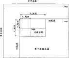
使用一个子数据包封装的特定可用的实例是选择性的刷新一个未压缩的如图10所示的图象1000。整个帧1002的属性(水平/垂直总数,图象宽度/高度等等)将通过辅助信道224传输,因为上述属性将与流的有效期保持等长的时间。在选择性的刷新的操作中,只有图象1000的一部分1004在每视频帧进行更新。所更新的矩形的四个X-Y坐标(即部分1004)必须在每帧传输,因为矩形的坐标值每一帧都不同。另一个实例是256色图象数据所需的颜色查找表(CLUT)数据的传输,其中8比特像素数据是256入口CLUT的入口,CLUT的内容必须进行动态更新。A particularly useful example of using a subpacket encapsulation is to selectively refresh an
单独的双向辅助信道224提供一个通道用来提供各种支持功能,用于链路设置和支持主链路操作和传送辅助信道应用数据,比如USB通信。例如,使用辅助信道224,显示装置可以将一些事件通知信源装置,比如同步丢失、数据包出错和训练会话的结果(将在下文描述)。例如,如果一个特定的训练会话失败,发射机102根据预先选择或者确定的已失败的训练会话的结果来调整主链路速率。使用这种方法,通过合并一个可调整的高速率的主链路和一个相应的慢而且非常可靠的辅助信道,从而形成一个闭环,允许在各种链路条件下进行可靠的操作。应当注意的是在一些情况下(如图5B所示的实例),一个逻辑双向辅助信道520可利用主链路222带宽的一部分522建立,来将数据从信源装置202传送到信宿装置204,以及一个单向的返回信道524从信宿装置204返回到信源装置202。在一些应用中,使用逻辑双向辅助信道将比使用图5A所示的半双工双向信道更理想。A separate bi-directional
在传输实际的数据包流开始前,发射机102通过链路训练会话而建立一个稳定的链路,这在概念上与调制解调器的链路设置是类似的。在链路训练中,主链路发射机102发送一个预先定义的训练模式,从而接收机104可以确定它是否能达到一个固定的比特/特征符锁定。在所描述的实施例中,发射机102和接收机104之间与建立相关的信号交换的训练是在辅助信道上执行的。根据本发明的实施例的一种链路训练模式如图11所示。如图,在训练会话的过程中,状态1代表最小行程长度,而状态2代表最大行程长度即接收机用来优化均衡器的长度。在状态3,只要链路质量已经比较合理,比特锁定和特征符锁定就都达到。典型的,训练时间大约是10ms,其中大概发送107个比特。如果接收机104没有达到固定锁定,它将通过辅助信道224通知发射机102,并且发射机102将减小链路速率并且重复训练会话。Before transmitting the actual packet stream, the
除了提供一个训练会话通道,辅助信道224也可用于传送主链路数据包流的描述符,从而大大减小主链路222数据包传输的开销。更进一步,辅助信道224可配置来传送扩展显示识别数据(EDID)信号来代替所有显示器上的显示数据信道(DDC)(EDID是一个VESA标准数据形式,包括关于显示器和它的性能的基本数据,包括出售者信息,最大图象尺寸,颜色特征,工厂预置定时,频率范围限制,以及显示器名称的特征字符串和序列号。上述信息存储在显示器中,并且用于通过位于显示器和PC图形适配器之间的DDC与系统进行通信。系统使用这些信息用来配置,使得显示器和系统能一起运作)。在一个扩展协议模式中,辅助信道可用于传输支持附加的数据种类所需的不同步和同步数据包来,比如键盘,鼠标和话筒。In addition to providing a training session channel, the
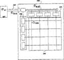
图12示出了根据本发明实施例的具有数据流调度装置1202的系统1200。应当注意的是系统1200是基于图5A和5B描述的系统500的,因此只能认为是本发明的一种实施例。因此,流调度装置1202被安装在或者连接到视频信源202,并且,顺序连接到复用器1204和数据缓冲器1206,该缓冲器适于仅存储用于在称为调度程序周期时间运行的Tsched期间用于传输一个链路数据流1208的输入数据流部分(S1,S2和S3)。在所描述的实施例中,数据缓冲器1206典型的是数十字节大小,最好小于60K字节,用于同步视频传输协议,比如FireWireTM。使用这种方法,链路效率(基于被可用连接带宽划分的数据流负载带宽总和的比较)大约是90%或更大。Fig. 12 shows a
在所描述的实施例中,连接数据流1208通过调度程序1202使用时分复用来从每个数据流S1,S2,和S3中分别结合尺寸数据包P1,P2和P3(其中数据包的大小反映了相应带宽,因为每个数据流和连接带宽相关)。如上所述,每个数据包的大小是特定数据流比特速率(SBR)和链路比特速率(LBR)的函数。特别的,特定数据流比特速率越大,表1所示的特定数据包的大小就越大。例如,如果链路比特速率LBR大约是2.5Gbps以及最大数据包大小是大约80链路符号(其中一个链路符号被定义为每个链路时钟一个的数据单元并通常是4ns),并且按照表1的假设,(即SBR1是1.0Gbps,SBR2是0.3125Gbps,以及SBR3是0.25Gbps),那么与数据流S1相关联的数据包P1是32个链路符号,而与数据流S2和S3相关联的数据包P2和P3相应的分别是10个和8个链路符号。应当注意的是在每个调度程序周期时间Tsched的开始,调度程序1202插入一个道内调整数据包(ILA)用于提供接收机204的散布工具,该数据包大约是2个链路符号的大小。因此在这个例子中,调度程序周期时间Tsched大约是(32+10+8+2)52个链路符号(每个链路符号代表大约4ns时可转化成大约208ns)。In the depicted embodiment, concatenated
还应当注意的是每个数据包P具有一个相关的数据符D和填充符N的有效数据比,与流比特速率(SBR)和链路比特速率(LBR)相关:It should also be noted that each packet P has an associated effective data ratio of data symbols D and filler N, related to the stream bit rate (SBR) and the link bit rate (LBR):
SBR/LBR=D/(D+N)SBR/LBR=D/(D+N)
因此在那些数据流被添加(或删除)而导致调度程序周期时间Tsched的增加(或减小)的情况下,数据包大小P通过改变与数据符D数量相关的填充符N的数量来保持恒定。因为数据流的特定数据包大小可以保持恒定,由于数据流的添加(或删除)调度程序周期时间Tsched增加(或减小),那么将填充符N的数量增加(或减小)来补偿Tsched的变化。在“简并(degenerate)”的情况下,只有一个单独数据流,那么就没有填充符N。Thus in case those streams are added (or removed) causing an increase (or decrease) in the scheduler cycle timeTsched , the packet size P is maintained by varying the number of filler symbols N in relation to the number of data symbols D constant. Since the specific packet size of a data flow can be kept constant, the scheduler cycle time Tsched increases (or decreases) due to the addition (or removal) of data flows, then the number of fillers N is increased (or decreased) to compensate for the increase (or decrease) of Tsched Variety. In the case of "degenerate", there is only one single data stream, then there is no filler N.
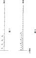
图13示出了根据本发明的数据流1210的更详细的部分1300。特殊的,图13表示使用表1所示的值的数据流1208的数据符D和填充符N的分布。还应当注意的是动态添加或删除特定数据流,并不会对其他的数据流产生影响。因此,图14说明了添加了一个具有流比特速率为0.625Gbps的第四数据流S4,对应的数据包大小P4是20个链路符号,导致Tsched从52个链路符号变成72个链路符号(一个链路符号等于4ns,对应于288ns)。但是,为了保持特定数据包大小P1,P2,和P13的恒定,每个数据包的填充符N都要增加。相反的,当一个数据流被删除的情况下(比如S3),调度程序周期时间Tsched将被相应的减小,而通过增加和填充符N相关的数据符D的数量来补偿。在“简并”的情况下,所有的数据流中之一被删除,那么其它的数据包就没有填充符N并且不需要缓冲器来模拟上述的光栅扫描传输协议。Figure 13 shows a more detailed portion 1300 of a data flow 1210 according to the present invention. In particular, FIG. 13 shows the distribution of data symbols D and filler symbols N of the
而且,在“简并”连接的情况下,当数据流1208是一个单独的未压缩的视频流(如图15所示),ILA数据包位于S1的空闲期间(水平消隐区域),并且有效显示区域由数据符D和填充符N的混合来表示(如图16)。Moreover, in the case of a "degenerate" connection, when the
还应当注意的是数据符D的相关数量提供一个嵌入时间戳,因为通过对和不与特定数据流相关的数据符相关的特定数据流的数据符D计数来提供流时钟用于特定数据流。例如,在图13所示的情况下,为了恢复特定数据流的流时钟Fstream_clk,可以通过简单的将流数据符的数量(M)与填充符和流数据符的总数(P)进行比较来确定。更特别的,流时钟Fstream_clk由下式确定:It should also be noted that the relative number of data symbols D provides an embedded time stamp since the stream clock is provided for a particular data stream by counting the data symbols D of a particular data stream associated with data symbols not associated with a particular data stream. For example, in the case shown in Figure 13, in order to recover the stream clock Fstream_clk for a particular stream, one can simply compare the number of stream symbols (M) with the total number of filler symbols and stream symbols (P) Sure. More specifically, the stream clock Fstream_clk is determined by the following formula:
Fstream_clk=(M/P)*Flink_clkFstream_clk = (M/P)*Flink_clk
其中M和P可通过接收器204测定。Where M and P can be determined by the
图17示出了根据本发明实施例的调度多个数据流的详细过程1700的流程图。该处理1700通过发射机将属性数据发送到接收机从步骤1702开始。在描述的实施例中,属性信息通过连接发射机和接收机的辅助信道来发送。然后,在步骤1704,接收机分配充足的资源(如果可用)来接收和处理输入的数据流。在发射机接收数据流的步骤1706之后,流传输调度程序在步骤1708形成一个链路数据流,而在1710连接数据流通过主链路从发射机发送到接收机。然后在步骤1712,在那些情况下,一个附加数据流被添加到接收机上,并且在步骤1714接收机能够接收并处理被添加的数据流,在步骤1716新的数据流被透明的添加,使得先前传输的数据流的数据包大小保持恒定。FIG. 17 shows a flowchart of a detailed process 1700 for scheduling multiple data streams according to an embodiment of the present invention. The process 1700 begins at
图18示出了根据本发明的实施例形成链路数据流的详细过程1800的流程图。应当注意的是过程1800是形成过程1700中的操作1708的一个特殊的执行方式。因此,在1802传输调度程序确定发射机到接收器链路的主链路的连接比特速率以及在1804确定每个将传输数据流的流比特速率。然后,在1806,根据流比特速率,链路比特速率和预定的最大数据包大小来确定数据包的大小。然后在步骤1808,每个数据流的数据包都形成,每个包括一定数量的数据符和填充符。一旦数据包形成并且在一个单独的传输调度程序周期时间内,在1810传输调度程序(使用时分复用)从每个将发送到接收器的数据流中结合一些数据包,并且在1812添加一个道间分布数据包到结合的数据包。在1814中,传输调度程序通知发射机传送结合的数据包到接收机,并且重复步骤1808到1814直到在步骤1816确定传输已经终止。FIG. 18 shows a flowchart of a detailed process 1800 of forming a link data stream according to an embodiment of the present invention. It should be noted that process 1800 is a specific implementation of
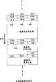
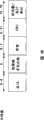
图19说明了根据本发明实施例的系统200的逻辑层1900。应当注意的是具体的执行方式将根据不同的应用而改变,通常来说,信源(比如视频信源202)由一个包括发射机硬件的信源物理层1902,一个包括复用硬件和状态机器(或固件)的信源链路层1904,以及一个比如音频/视频/图形硬件和相关软件的数据流信源1906构成。类似的,显示装置包括一个物理层1908(包括各种接收机硬件),一个包括解复用硬件和状态机器(或固件)的接收链路层1910,以及包括显示/计时控制硬件和可选固件的流接收器1912。一个信源应用程序层1914定义信源和链路层1904相互通信的格式,一个接收器应用程序层1916定义接收器1912和接收器链路层1910相互通信的形式。Figure 19 illustrates a
下面将详细介绍各层。Each layer is described in detail below.
信源装置物理层source device physical layer
在所描述的实施例中,信源装置物理层1902包括一个电气子层1902-1和一个逻辑子层1902-2。电气子层1902-1包括所有的接口初始化操作电路,比如热插/拔检测电路,驱动器/接收机/终端电阻,并行到串行/串行到并行转换器,以及扩频电容PLL。逻辑子层1902-2包括下列电路,用于打包或/分解包,数据加扰/解扰,链路训练的模式产生,时间基准恢复电路,以及数据编码/解码比如8B/10B(在ANSI X3.230-1994,条款11中提及)用于为主链路222和辅助信道224的ManchesterII(如图21)提供256连接数据特征符和12控制特征符(图13表示一实例)。In the depicted embodiment, the source device
应当注意的是8B/10B编码算法在下列资料中描述,比如美国专利号为4486739,已经结合在本申请资料中。本领域技术人员已知,8B/10B编码是块编码,即将8比特的数据块编码成10比特的码字用于串行传输。另外,8B/10B传输编码将在一个最大行程长度为5,将一字节宽的具有随机数1s和0s的数据流转换成具有1s和0s的DC平衡流。上述代码提供足够的信号转换来使得接收机进行可靠的时钟恢复,比如无线电发收机110。更多的,DC平衡数据流被证明更有利于光纤和电磁导线连接的传输。串行流中的1s和0s的平均数将被保持等于或者接近平均水平。8B/10B传输编码限制数字1s和0s的不一致在6和4个比特块的边界在-2,0,或者2。编码方案也能执行其他的编码用于发送信号,称为指令编码。It should be noted that the 8B/10B encoding algorithm is described in, for example, US Patent No. 4,486,739, which is incorporated herein. Those skilled in the art know that 8B/10B encoding is block encoding, that is, encoding an 8-bit data block into a 10-bit code word for serial transmission. Additionally, 8B/10B transfer encoding will convert a one-byte wide data stream with random 1s and 0s into a DC-balanced stream with 1s and 0s at a maximum run length of 5. The code described above provides sufficient signal transitions to allow reliable clock recovery by a receiver, such as
应当注意的是为了避免由于未压缩显示数据所呈现的重复比特模式(因而减小EMI),通过主链路222传输的数据应当在进行8B/10B编码前首先经过加扰。所有的数据,除了训练数据包和特殊特征符,都将被加扰。加扰功能由线性反馈移位寄存器(LFSR)来完成。当进行数据加密时,LFSR的初始值将根据加密密钥的设置确定。如果是不经加密的加扰,那么该初始值是固定的。It should be noted that in order to avoid repetitive bit patterns (and thus reduce EMI) due to uncompressed display data, the data transmitted over the
由于数据流属性是通过辅助信道224进行传输,主链路数据包头只是作为流识别号,因此大大减小了开销并且将链路带宽最大化。还应当注意的是主链路222和辅助信道224都没有单独的时钟信号线。使用这种方法,接收机在主链路222和辅助信道224上对数据取样并且从输入的数据流中提取时钟。接收机电气子层中任意锁相环(PLL)的快速相位锁定电路是非常重要的,因为辅助信道224是半双工双向的并且其通信方向改变的很快,因此在辅助信道接收机状态的PLL在16个数据周期内锁定,要归功于ManchesterII(MII)编码的频率和均衡信号传输。Since the attribute of the data flow is transmitted through the
在链路设置时刻,主链路222的数据速率是通过辅助信道224进行信号交换而协商的。在处理过程中,已知的一系列训练数据包将通过主链路222以最高的链路速度发送。成功或失败将通过辅助信道224反馈给发射机102。如果训练失败了,主链路的速率便减慢,并且重复训练直到成功为止。使用这种方法,信源物理层1902对于电缆问题有更好的耐久性,并且因此更适用于外部主机到显示器的应用。但是不象传统的显示接口,主信道链路数据速率是从像素时钟速率分解而来的。将链路数据速率设置成链路带宽超过传输流的总和带宽。At link setup time, the data rate of the
信源装置链路层Source Device Link Layer
信源链路层1904进行链路的初始化和管理。例如,通过接收一个由显示器通电而产生的热插检测事件或者显示器电缆到信源物理层1902的连接,信源装置链路层1904通过在辅助信道224的内部交换估计接收机的性能,从而确定由训练会话确定的最大主链路速率、接收机中的时间基准恢复单元的数量、两端的可用缓冲器的大小、可用的USB扩展,然后通知流信源1906一个相关的热插事件。另外,基于来自流信源1906的请求,信源链路层1904读出显示器的性能(EDID或者等效的)。在常规操作中,信源链路层1904通过辅助信道224将流的属性发送到接收机104,通知流信源1904主链路222是否有足够的资源来处理请求的数据流,通知流信源1904一些链路失败事件比如同步丢失和缓冲器溢出,并且将流信源1904所提交的MCC指令通过辅助信道224发送到接收机。所有信源链路层1904和流信源/信宿之间的通信都使用应用程序概况层1914所定义的格式。The
应用简档层(信源和信宿)Application profile layer (source and sink)
通常,应用程序简档层定义流信源(或信宿)和相关的链路层接口的形式。由应用程序简档层定义的形式将划分成下列种类,应用独立格式(链路状态查询的链路消息)和应用相关格式(主链路数据映射,接收器的时间基准恢复等式,以及如果可用,信宿容量/流属性消息的子数据包式)。应用程序简档层支持下列颜色格式,24比特RGB,16比特RG2565,18比特RGB,30比特RGB,256色RGB(基于CLUT),16比特,CRCr422,20比特YCbCr422,和24比特YCbCr444。In general, the application profile layer defines the form of flow sources (or sinks) and associated link layer interfaces. The forms defined by the application profile layer will be divided into the following categories, application independent format (link message for link state inquiry) and application dependent format (main link data map, receiver's time reference recovery equation, and if Available, subpackets of sink capacity/flow attribute messages). The application profile layer supports the following color formats, 24-bit RGB, 16-bit RG2565, 18-bit RGB, 30-bit RGB, 256-color RGB (based on CLUT), 16-bit, CRCr422, 20-bit YCbCr422, and 24-bit YCbCr444.
例如,显示装置应用程序简档层(APL)1914实际上是一个应用程序接口(API)描述用于流信源/信宿通过主链路222的通信格式,其中包括从接口100数据发送或者接收的Express形式。因为APL1914的一些方面(比如电源管理指令格式)是基线监视功能,它们对于接口100的所有应用是通用的。而其它不是基线监视功能的——比如数据映射格式和流属性格式,对于一个应用或一种将传输的同步流是唯一的。不考虑应用,流信源1904向信源链路层1914询问来确认在任何数据包流在主链路222上传输之前,主链路222是否能掌握即将收到的数据流。For example, the display device application profile layer (APL) 1914 is actually an application program interface (API) that describes the communication format used for streaming source/sink through the
当它确定主链路222能够支持即将到达的数据包流,流信源1906将流属性发送到流链路层1914,然后通过辅助信道224传输到接收机。这些属性是被接收器使用来识别一个特定流的数据包,从流中恢复原始数据,并且将它转换成流本来的数据速率的格式。数据流的属性信息根据应用而定。When it determines that the
在那些所需的带宽在主链路222上不可用的情况下,流信源1914可执行校正的操作,例如减小图象刷新速率或者颜色深度。In those instances where the required bandwidth is not available on the
显示装置物理层display device physical layer
显示装置物理层1916将显示装置链路层1910和显示装置APL1916从用于链路数据传输/接收的信号技术分离开来。主链路222和辅助信道224都具有他们自己的物理层,其中每个都由包括连接器规范的一个逻辑子层和一个电气子层构成。例如,半双工双向辅助信道224在其链路的两端具有一个发射机和一个接收机,如图22所示。一个逻辑子层1908-1提供一个具有链路特征符的辅助链路发射机2902,然后特征符被串行化并且传输到相应的辅助链路接收机2904。然后接收机2904从辅助链路224接收串行化的链路特征符,并且在链路特征时钟对其去串行。应当注意的是,信源逻辑子层的主要功能包括信号编码,打包,数据加扰(为减小EMI),以及发射机端口的训练模式产生。而在接收机端口,接收机逻辑子层的主要功能包括信号解码,解包,数据解扰以及时间基准恢复。
辅助信道auxiliary channel
辅助信道逻辑子层的主要功能包括数据编码和解码,数据的成帧/解帧并且辅助信道的协议有两种选择:独立协议(仅限于点到点拓扑结构的链路设置/管理功能)是一种轻量级的协议,能够通过链层状态机器或者固化软件来管理;以及扩展协议,支持其他的数据种类比如USB通信和拓扑结构比如链接装置。应当注意的是,尽管在两种协议的数据成帧不同,但是不考虑所使用的协议,数据的编码和解码方案是相同的。The main functions of the logical sublayer of the auxiliary channel include data encoding and decoding, framing/deframing of data and there are two options for the protocol of the auxiliary channel: the independent protocol (limited to the link setting/management function of the point-to-point topology) is A lightweight protocol that can be managed by a chain-level state machine or firmware; and an extended protocol that supports other data types such as USB communication and topologies such as link devices. It should be noted that although the framing of the data is different in the two protocols, the encoding and decoding scheme of the data is the same regardless of the protocol used.
仍然参照图29,辅助信道电气子层包括发射机2902和接收机2904。逻辑子层提供给发射机2902链路特征符,将其串行化并传输出去。接收机2904从链路层接收串行化的链路特征符,并且依次将其在链路特征时钟解序列。辅助信道224的正极和负极信号如图所示在链路的每个端50ohm的终端电阻处导入地。在所描述的实现中,驱动电流是可根据链路条件改写的,能从大约8mA变化至24mA,形成的电压差pp范围大约是400mV到大约1.2mV。在电子空闲模式中,正极还是负极信号都不被驱动。当从电子空闲状态开始传输时,SYNC模式必须传输并且要重新建立链路。在所描述的实施例中,SYNC模式包括在ManchesterII编码时在28倍辅助信道的差分对在时钟速率和接下来四个1秒内跳变。信源装置中的辅助信道控制器通过事先驱动或检测辅助信道224的正极和负极信号,来检测热插和热拔事件。Still referring to FIG. 29 , the secondary channel electrical sublayer includes a transmitter 2902 and a receiver 2904 . The logic sublayer provides the link signature to the transmitter 2902, serializes it and transmits it. The receiver 2904 receives the serialized link signature from the link layer and deserializes it in turn at the link signature clock. The positive and negative signals of the
主链路main link
在所描述的实施例中,主链路222支持离散可变的链路速率,该速率是本地晶体频率(如图3代表性的将链路速率设置为与本地晶体频率24MHz一致)。如图16所示,主链路222(单向信道)在信源装置仅具有一个发射机1602,以及在显示装置仅具有一个接收机1604。In the depicted embodiment, the
如图,电缆2304是包括双绞线的形式,红(R),绿(G),和蓝(B)视频信号的其中之一在一个典型的基于RGB颜色的视频系统(比如基于PAL的TV系统)中提供。本领域技术人员已知,双绞线是一种电缆,将两根独立绝缘的电线缠绕在一起。一根电线运送信号,而另一根电线被聚集起来并且吸收信号干扰。应当注意的是在一些其他系统中,信号也可以是用于NTSC视频TV系统的基于合成的信号(Pb,Pr,Y)。在电缆中,每对双绞线都是独立屏蔽的。提供两个管脚,用于12V电源和地。每个不同对的特征差异是100ohm+/-20%。整个电缆也是屏蔽的。外屏蔽层和独立的屏蔽层在两端缩短到连接器外壳。连接器外壳缩短安装在信源装置中的地。一个如图24所示的连接器2400具有排成一列的13个管脚,以及一个输出管脚对于信源装置端和显示装置端的连接器是相同的。信源装置提供电源。As shown, cable 2304 is in the form of twisted-pair wires comprising one of red (R), green (G), and blue (B) video signals in a typical RGB color-based video system (such as a PAL-based TV system). As known to those skilled in the art, a twisted pair is a cable in which two individually insulated wires are twisted together. One wire carries the signal, while the other wire is bunched up and absorbs signal interference. It should be noted that in some other systems the signal may also be a composite based signal (Pb, Pr, Y) for the NTSC video TV system. In the cable, each twisted pair is individually shielded. Two pins are provided for 12V power and ground. The characteristic difference for each different pair is 100ohm +/- 20%. The entire cable is also shielded. The outer shield and separate shield are shortened to the connector housing at both ends. The connector housing shortens the ground installed in the source device. A
主链路222在其两端终止,并且因为主链路222是AC连接的,终止电压可以是0V(地)和3.6V之间的任意值。在所描述的执行方式中,驱动电流是可根据链路条件改写的,能从大约8mA变化至24mA,形成的电压差pp大约是400mV到大约1.2mV。最小电压摆动值是利用训练模式为每个连接选择的。为电源管理模式提供一个电子空闲状态。在电子空闲状态,正极和负极信号都不被驱动。当从电子空白状态开始传输时,发射机必须指示一个会话建立来重新与接收机建立连接。The
状态图State diagram
下面本发明将根据图25和26所示的状态图来描述。相应的,下面将讨论图25所示的信源状态图。在关的状态2502,系统是关闭的因此信源也不工作。如果信源开始启动,系统就转换到等待状态2504用于电源节省和接收机检测。为了检测接收机是否存在(比如热插/拔),辅助信道具有定期脉冲(比如每10mslus)并且在驱动时在终端电阻处测量电压落差。如果根据所测量的电压落差确定接收机存在,系统将转换到检测接收机状态2506,说明已经检测到接收器,即检测到了热插事件。但是,如果没有检测到接收机,那么接收机检测将持续直到检测到接收器或者超过检测时间。应当注意的是在一些情况下,信源装置可能选择到“关”状态,其中将不进行更进一步的显示检测。The present invention will be described below with reference to the state diagrams shown in FIGS. 25 and 26 . Accordingly, the source state diagram shown in Figure 25 will be discussed below. In the
如果在状态2506一个显示器热拔事件被检测到了,那么系统将回到等待状态2504。否则信源将用一个正极和负极信号驱动辅助信道来使接收机运作并且如果有的话,就检测接收器接下来的响应。如果没有接收到响应,那么接收器没有开始运作并且信源保持在状态2506。但是如果从显示器接受了一个信号,那么显示器已经开始运作并且信源准备读出接收器连接的性能(比如最大链路速率,缓冲器大小以及时间基准恢复单元)并且系统转换到一个主链路初始化状态2508,准备开始一个训练开始通知阶段。If in state 2506 a display hot unplugging event is detected, the system will return to wait
在这个时候,通过在主链路以设置链路速率发送训练模式并且检测一个相关的训练状态来开始训练会话。接收机为三个阶段的每一个都指定一个通过/失败比特,发射机将只根据检测通过的装置检测到了通过才进行到下一个阶段,主链路准备于链路速率。在这个时候,接口转换到一个常规操作状态2210,否则,链路速率将减小并且训练会话将重复。在常规操作状态2510,信源将持续的定期监视一个链路状态索引,当失败时,检测到一个热拔事件并且系统转换到一个等待状态2504来等待一个热插事件的检测。但是,如果检测到了同步丢失,那么系统转换到状态2508来进行主链路再次初始化事件。At this point, the training session is started by sending the training pattern on the main link at the set link rate and checking for an associated training status. The receiver assigns a pass/fail bit to each of the three stages, the transmitter will only proceed to the next stage if a pass is detected by the device that detected the pass, and the main link is ready at the link rate. At this point, the interface transitions to a normal operating state 2210, otherwise, the link rate will be reduced and the training session will repeat. In the
图26示出了下述的显示状态框2600。在状态2602,没有检测到电压,显示器进入关状态。在等待模式状态2604,主链路接收机和辅助信道从动装置都在电子空闲状态,辅助信道从动端口的终端电阻器的电压差被监视为了一个预先确定的电压值。如果检测到了电压值,那么辅助信道从动端口被打开,指示一个热插事件并且系统进入显示状态2606。否则,显示器保持在等待状态2604。在状态2606(主链路初始化阶段)如果检测到了显示器,那么辅助从动端口将全部打开,并且发射机响应与接收机连接性能读出指令,显示器状态转换到2608,否则如果在辅助信道上一个预定时期内没有活动,那么辅助信道从动端口将进入等待状态2604。Figure 26 shows a display status box 2600 described below. In state 2602, no voltage is detected and the display enters an off state. In the standby mode state 2604, both the main link receiver and the auxiliary channel slave devices are in an electronic idle state, and the voltage difference across the termination resistors of the auxiliary channel slave ports is monitored for a predetermined voltage value. If a voltage value is detected, then the auxiliary channel slave port is opened, indicating a hot plug event and the system enters display state 2606. Otherwise, the display remains in a wait state 2604. In state 2606 (main link initialization stage) if detected display, auxiliary slave port will all be opened so, and transmitter responds to the instruction that reads connection performance with receiver, and display state transitions to 2608, otherwise if on auxiliary channel a After a predetermined period of inactivity, the secondary channel slave port will enter a wait state 2604.
在一个训练开始通知阶段,显示器通过利用训练模式调整均衡器,更新每个阶段的结果来响应于会话初始化。如果建立失败,那么将等待下一个训练会话,如果建立成功,那么将进入正常操作状态2610。如果在辅助信道或主链路(用于建立)一个预定时期内(例如10ms)没有活动,那么将辅助信道从属接收器口设置等待状态2604。During a training start notification phase, the display responds to session initialization by adjusting the equalizer using the training mode, updating the results of each phase. If the establishment fails, it will wait for the next training session, and if the establishment is successful, it will enter the normal operation state 2610. If there is no activity on the auxiliary channel or main link (for setup) for a predetermined period of time (eg, 10 ms), then the auxiliary channel slave receiver port is set to wait state 2604.
图27-31示出了交叉平面显示接口的特定执行方式。27-31 illustrate specific implementations of the cross-plane display interface.
图27示出了一个根据本发明的PC母板2000,具有包括发射机2704的板上图形机构2002。应当注意的是发射机2704是图1所示的发射机102的一个特定例子。在所描述的实施例中,发射机2704连接到一个安装在母板2000上的连接器2704(沿连接器2400的沿线),母板通过连接显示装置2710的双绞线顺序连接到显示装置2708。FIG. 27 shows a PC motherboard 2000 having an on-board graphics mechanism 2002 including a transmitter 2704 in accordance with the present invention. It should be noted that transmitter 2704 is a specific example of
本领域已经公知,PCI Express(由CA,Santa Clare的Intel公司开发)是一个高带宽,低管脚数量,串行化的内部连接技术,和现有PCI的下结构保持软件兼容性。在这个配置中,PCIExpress端口能增加来变得适应交叉平台接口的要求,其中该接口能直接驱动一个显示装置或者利用如图所示的安装在母板上的连接器。As known in the art, PCI Express (developed by Intel Corporation of Santa Clare, CA) is a high bandwidth, low pin count, serialized internal connection technology, and maintains software compatibility with the underlying structure of the existing PCI. In this configuration, PCIExpress ports can be added to accommodate a cross-platform interface that can drive a display directly or using the motherboard-mounted connector as shown.
在将连接器安装到母板上是不现实的情况下,信号可以被导通过PCIExprss母板的SDVO槽并且回到如图28使用一个无源卡连接器的PC的背面。就像具有添加卡的电流产生情况下,一个添加图象卡可以代替图30所示的板上图形机构。In cases where it is impractical to mount the connector to the motherboard, the signal can be routed through the SDVO slot of the PCIExpress motherboard and back to the back of the PC using a passive card connector as shown in Figure 28. As in the case of current generation with add-on cards, an add-on graphics card can replace the on-board graphics mechanism shown in Figure 30.
在应用在笔记本的情况下,母板图形机构上的发射机将通过内部电缆驱动,一个集成的接收机/TCON可以直接驱动面板。对于一种最有效的执行方式,接收机/TCON被安装在面板上,因此如图31所示将内部连接电缆的数量减小到8或10。In the case of a notebook application, the transmitter on the motherboard graphics mechanism would be driven via an internal cable, and an integrated receiver/TCON could drive the panel directly. For a most efficient implementation, the receiver/TCON is mounted on the panel, thus reducing the number of internal connecting cables to 8 or 10 as shown in Figure 31.
所有以上的例子假设的是集成的发射机。但是,通过AGP或者SDVO槽相应的将一个独立的发射机集成到PCI和PCIExpress环境中,也是相当可行的。一个单独的发射机可以输出流而不需要任何图形硬件或者软件方面的改变。All the above examples assume an integrated transmitter. However, it is also quite feasible to integrate a separate transmitter into PCI and PCIExpress environments via AGP or SDVO slots, respectively. A single transmitter can output the stream without any graphics hardware or software changes.
流程实施例Process example
下面将根据一些流程图来描述本发明的方法,其中每个都描述一个实现本发明的特定处理过程。特别的,图32-36描述了许多单独应用或者联合应用而描述本发明一些方面的互相联系的处理。The method of the present invention will be described below according to some flowcharts, each of which describes a specific process for implementing the present invention. In particular, Figures 32-36 depict a number of interrelated processes that are used individually or in combination to describe aspects of the invention.
图32示出了一个流程图,详细说明根据本发明实施例的确定接口100的操作模式的过程3200。在处理过程中,如果视频信源和显示装置都是数字的话,那么操作模式将只被设置为数字模式。否则,操作模式将被设置为模拟模式。应当注意的是本文中所述的“模拟模式”可同时包括传统的VGA模式,以及具有不同嵌入分布信号和双向边带的不同模拟视频的增强模拟模式。下面将介绍这个增强模拟模式。FIG. 32 shows a flowchart detailing a process 3200 for determining the mode of operation of the
在步骤3202,视频信源将询问来确定视频信源是否支持模拟或是数字数据。如果视频信源只支持模拟数据,那么连接装置100的操作模式将被设置成模拟(步骤3208),然后处理过程结束(步骤3202)。In
如果视频信源可以输出数字数据,那么处理过程持续到步骤3206。然后显示装置将询问来确定显示装置是否被指定来接收数字数据。如果显示装置只支持模拟数据,那么连接装置的操作模式将被设置成模拟(步骤3208),然后处理过程结束(步骤3212)。否则,连接装置的操作模式将被设置成数字(步骤3210)。例如,一个位于连接装置中的处理器可以控制转换来将模式设置成数字。通常来说,连接装置只有当视频信源和视频接收器同时操作于相应的数字模式时,才按照完全的数字模式来操作。If the video source is capable of outputting digital data, processing continues to step 3206. The display device will then query to determine if the display device is designated to receive digital data. If the display device only supports analog data, then the operating mode of the connected device will be set to analog (step 3208) and the process ends (step 3212). Otherwise, the operation mode of the connected device will be set to digital (step 3210). For example, a processor located in the connected device can control the switch to set the mode to digital. Generally speaking, the connecting device operates in a full digital mode only when both the video source and the video sink operate in the corresponding digital modes simultaneously.
图33示出了一个流程图,详细说明了根据本发明一些方面的提供实时视频图象质量检测的过程3300。在这个例子中,步骤3300的所有确定过程都是由一个连接到显示接口的处理器来完成。FIG. 33 shows a flowchart detailing a process 3300 for providing real-time video image quality detection in accordance with some aspects of the present invention. In this example, all determinations in step 3300 are performed by a processor connected to the display interface.
在步骤3300,从视频信源接收一个视频信号。然后,由视频信源提供与接收的视频信号相关的信号质量测试模式(步骤3302)。在步骤3304,根据质量测试模式,作出误码率的确定。然后,判断该误码率是否大于一个阈值(步骤3306)。如果误码率没有大于阈值,那么将确定是否有更多的视频帧(步骤3314)。如果确定没有更多的视频帧,那么处理回到步骤3300。否则,处理结束。In step 3300, a video signal is received from a video source. A signal quality test pattern associated with the received video signal is then provided by the video source (step 3302). At step 3304, a bit error rate determination is made based on the quality test pattern. Then, it is judged whether the BER is greater than a threshold (step 3306). If the bit error rate is not greater than the threshold, then it will be determined whether there are more video frames (step 3314). If it is determined that there are no more video frames, then processing returns to step 3300. Otherwise, processing ends.
但是,如果在步骤3306确定比特错误速率大于阈值,那么将确定(步骤3308)比特速率是否大于一个最小比特速率。如果比特速率大于一个最小比持速率,那么将降低比特速率(步骤3310)并且处理回到步骤3306。如果比特速率不大于最小比特速率,那么模式转换到模拟模式(步骤3312)并且处理结束。However, if at step 3306 it is determined that the bit error rate is greater than the threshold, then it will be determined (step 3308) whether the bit rate is greater than a minimum bit rate. If the bit rate is greater than a minimum bit rate, then the bit rate will be reduced (step 3310) and processing returns to step 3306. If the bit rate is not greater than the minimum bit rate, then the mode switches to analog mode (step 3312) and the process ends.
图34示出了一个根据本发明实施例的链路设置处理过程3400的流程图。处理3400在接收一个热插检测事件通知的步骤3402开始。在3404通过相关辅助信道来确定一个最大数据速率,一个包括在接收机中的一定数量的时间基准恢复单元,以及可用的缓冲器大小的方式,来作出主链路询问。然后,在3406,通过训练会话的方式确定最大链路数据速率,以及在3408,数据流信源被通知热插事件。在3410,通过辅助信道来确定显示器的性能(例如使用EDID),并且显示器在3412响应于询问,然后,在3414形成了主链路训练会话的合作。FIG. 34 shows a flowchart of a link setup process 3400 according to an embodiment of the present invention. Process 3400 begins at step 3402 of receiving a hot plug detection event notification. Primary link queries are made at 3404 by determining a maximum data rate associated with the secondary channel, a number of time reference recovery units included in the receiver, and available buffer sizes. Then, at 3406, the maximum link data rate is determined by means of the training session, and at 3408, the data flow source is notified of the hot plug event. At 3410, the capabilities of the display are determined via the secondary channel (eg, using EDID), and the display responds to the query at 3412, and then, at 3414, forms a partnership for the primary link training session.
然后在3416,流信源通过辅助信道将流属性发送到接收器3418,然后在3420流信源通知该主链路是否能够支持所要求的数据流的数量。在3422,不同的数据包通过添加相关的数据包头而形成,并且在3424复用一定数量的信源流被调度。在3426,确定链路状态是否良好。当连接状态不成功,那么信源将被通知一个连接失败事件3428,否则,在3430链路数据流将根据不同的数据包头重组为原来的流。在3432,重组的数据流传递到显示装置。Then at 3416, the flow source sends flow attributes to the receiver via the
图35示出了一个详细描述根据本发明实施例的执行训练会话的过程3500的流程图。应当注意的是所述的训练会话的过程3500是图32所示的操作3206的一种执行方式。训练会话通过在3502通过主链路按照设置链路速率向接收器发送训练模式而开始。一个根据本发明实施例的典型的链路训练模式如图11所示。如图所示,在训练会话过程中,阶段1代表最短的行程长度而阶段2代表最长的。接收机利用这两个阶段来优化均衡器。在阶段3,只要链路质量合理,那么比特锁定和特征锁定都已经达到。在3504,接收机检查一个相关的建立状态,并且基于这个训练状态检查结果,接收器在3506为三个阶段的每个和发射机指定一个通过/失败比特。在每个阶段,接收器将只在检测到通过时的下一个阶段,在3510,如果接收器没有检测到通过,那么接收机将减小链路速率并且重复训练会话。主链路在3512当检测到通过时准备在链路速率。FIG. 35 shows a flowchart detailing a process 3500 for performing a training session in accordance with an embodiment of the invention. It should be noted that the described training session process 3500 is an implementation of
图36说明了一个用于执行本发明的计算机系统3600。计算机系统3600只是执行本发明的图形系统的一个例子。计算机系统包括中央处理单元(CPU)3610,随机访问存储器(RAM)3620,只读存储器(ROM)3625,一个或多个外围设备3630,图形控制器3660,主存储装置3640和3650,以及数字显示单元3670。对于本领域技术人员是已知的,ROM能向CPU3610单向的传送数据和指令,而RAM可典型的用于双向的传送数据和指令。CPU3610包括一些处理器。两个主存储装置3640和3650都包括任何适当的计算机可读媒体。一个第二存储媒体880,典型的是一个块存储器,也能双向连接到CPU3610并且提供额外的数据存储容量。块存储器880是计算机可读媒体可以用于存储程序,包括计算机代码,数据或类似的。典型的,块存储器880是一个比如硬盘或者磁带的,通常比主存储装置3640,3650要慢的存储媒体。块存储装置880可以是磁带或纸带读取器的形式或者其他公知的装置。应当理解的是块存储装置880中的信息,在合适的情况下,可能被按照标准形式被结合为RAM3620的一部分,作为虚拟内存。Figure 36 illustrates a
CPU3610也可连接到一个或多个输入/输出装置890,可包括但是不限于,比如下列装置,视频监视器,轨迹球,鼠标,键盘,话筒,触摸屏,传感卡读取器,磁带或纸带读取器,写字板,指示笔,声音或手写识别器,或者其他公知的输入装置,比如当然的,其他的计算机。最后,CPU3610可选择的连接到一个计算机或电信网络,例如因特网或者内联网,使用通常在3695示出的网络连接。使用这样的网络连接,CPU3610便可考虑从因特网接收信息,或者在执行上述操作方法步骤的过程中向网络输出信息。这样的信息,通常被CPU3610使用来作为一系列指令来执行,可从网络接收或者向其发送,例如以计算机数据信号并体现为负载波的形式。上述的装置和材料对于熟悉计算机硬件和软件技术的人来说是很熟悉的。
图形控制器3660产生模拟图象数据和一个相应的参考信号,并且将两个信号提供给数字显示单元3670。模拟图象数据能够通过例如,基于从CPU3610或外部编码器(未示出)接收的像素数据来产生。在一种实施例中,模拟图像数据是以RGB形式,并且参考信号包括VSYNC和HSYNC信号,对于本领域人员是熟知的。但是,应当理解的是,本发明能通过模拟图象,数据和参考信号的其他形式来执行。例如,模拟图象信号可包括视频信号数据,也具有相应的时间参考信号。
尽管只描述了本发明的少数几种实施例,应当理解的是本发明也能在不脱离本发明的精神和范围的情况下以其他的特定形式来实施。所述的实例只是举例说明,并不是严格限制,并且本发明并不限于在此所给出的细节,但是能在后附的权利要求书的范围以及等价的范围内做任何修改。While only a few embodiments of the invention have been described, it should be understood that the invention can also be embodied in other specific forms without departing from the spirit and scope of the invention. The examples described are illustrative only and not restrictive, and the invention is not limited to the details given here but is capable of any modification within the scope and range of equivalents of the appended claims.
尽管本发明已经根据一些优选实施例来描述,其他一些改进,改变和等同方式也落在本发明的范围内。应当注意的是有许多能同时执行本发明的操作和装置的等同方式。因此本发明的解释说明旨在包括所有的改进,改变和等同实施例,它们都落在本发明的真实精神和范围内。While the invention has been described in terms of preferred embodiments, other modifications, changes and equivalents also fall within the scope of this invention. It should be noted that there are many equivalents that can simultaneously perform the operations and means of the present invention. The description of the present invention is therefore intended to cover all modifications, alterations and equivalents which fall within the true spirit and scope of the present invention.
Claims (11)
Translated fromChineseApplications Claiming Priority (6)
| Application Number | Priority Date | Filing Date | Title |
|---|---|---|---|
| US50406003P | 2003-09-18 | 2003-09-18 | |
| US60/504060 | 2003-09-18 | ||
| US55235204P | 2004-03-10 | 2004-03-10 | |
| US60/552352 | 2004-03-10 | ||
| US10/909,085US7487273B2 (en) | 2003-09-18 | 2004-07-29 | Data packet based stream transport scheduler wherein transport data link does not include a clock line |
| US10/909085 | 2004-07-29 |
Publications (2)
| Publication Number | Publication Date |
|---|---|
| CN1602001A CN1602001A (en) | 2005-03-30 |
| CN1602001Btrue CN1602001B (en) | 2010-09-08 |
Family
ID=34199000
Family Applications (1)
| Application Number | Title | Priority Date | Filing Date |
|---|---|---|---|
| CN2004100874609AExpired - LifetimeCN1602001B (en) | 2003-09-18 | 2004-09-17 | Packet-based data stream transmission scheduling device and method for applying the device |
Country Status (7)
| Country | Link |
|---|---|
| US (1) | US7487273B2 (en) |
| EP (1) | EP1517295A3 (en) |
| JP (1) | JP2005173553A (en) |
| KR (1) | KR20050028869A (en) |
| CN (1) | CN1602001B (en) |
| SG (1) | SG110144A1 (en) |
| TW (1) | TWI353167B (en) |
Families Citing this family (89)
| Publication number | Priority date | Publication date | Assignee | Title |
|---|---|---|---|---|
| DE10252165A1 (en)* | 2002-11-09 | 2004-05-19 | Philips Intellectual Property & Standards Gmbh | Communications integrated circuit for implementation of send and receive functions of a network node, especially of a motor vehicle data bus node using the local interconnect network protocol, has an autonomous interface circuit |
| US7620062B2 (en)* | 2003-05-01 | 2009-11-17 | Genesis Microchips Inc. | Method of real time optimizing multimedia packet transmission rate |
| US20040218624A1 (en)* | 2003-05-01 | 2004-11-04 | Genesis Microchip Inc. | Packet based closed loop video display interface with periodic status checks |
| US7567592B2 (en)* | 2003-05-01 | 2009-07-28 | Genesis Microchip Inc. | Packet based video display interface enumeration method |
| US8068485B2 (en) | 2003-05-01 | 2011-11-29 | Genesis Microchip Inc. | Multimedia interface |
| US7068686B2 (en) | 2003-05-01 | 2006-06-27 | Genesis Microchip Inc. | Method and apparatus for efficient transmission of multimedia data packets |
| US8059673B2 (en)* | 2003-05-01 | 2011-11-15 | Genesis Microchip Inc. | Dynamic resource re-allocation in a packet based video display interface |
| US7424558B2 (en)* | 2003-05-01 | 2008-09-09 | Genesis Microchip Inc. | Method of adaptively connecting a video source and a video display |
| US7405719B2 (en)* | 2003-05-01 | 2008-07-29 | Genesis Microchip Inc. | Using packet transfer for driving LCD panel driver electronics |
| US20040221315A1 (en)* | 2003-05-01 | 2004-11-04 | Genesis Microchip Inc. | Video interface arranged to provide pixel data independent of a link character clock |
| US8204076B2 (en)* | 2003-05-01 | 2012-06-19 | Genesis Microchip Inc. | Compact packet based multimedia interface |
| US6992987B2 (en)* | 2003-05-01 | 2006-01-31 | Genesis Microchip Inc. | Enumeration method for the link clock rate and the pixel/audio clock rate |
| US7733915B2 (en)* | 2003-05-01 | 2010-06-08 | Genesis Microchip Inc. | Minimizing buffer requirements in a digital video system |
| US7839860B2 (en)* | 2003-05-01 | 2010-11-23 | Genesis Microchip Inc. | Packet based video display interface |
| US7088741B2 (en) | 2003-05-01 | 2006-08-08 | Genesis Microchip Inc. | Using an auxilary channel for video monitor training |
| US20040221312A1 (en)* | 2003-05-01 | 2004-11-04 | Genesis Microchip Inc. | Techniques for reducing multimedia data packet overhead |
| US20040218599A1 (en)* | 2003-05-01 | 2004-11-04 | Genesis Microchip Inc. | Packet based video display interface and methods of use thereof |
| KR100698620B1 (en)* | 2003-06-16 | 2007-03-21 | 삼성전자주식회사 | Digital Transmission / Reception System with Robust Error Correction Coding Device and Its Error Correction Coding / Correcting Method |
| US7487273B2 (en) | 2003-09-18 | 2009-02-03 | Genesis Microchip Inc. | Data packet based stream transport scheduler wherein transport data link does not include a clock line |
| US7800623B2 (en)* | 2003-09-18 | 2010-09-21 | Genesis Microchip Inc. | Bypassing pixel clock generation and CRTC circuits in a graphics controller chip |
| US7613300B2 (en)* | 2003-09-26 | 2009-11-03 | Genesis Microchip Inc. | Content-protected digital link over a single signal line |
| US7634090B2 (en)* | 2003-09-26 | 2009-12-15 | Genesis Microchip Inc. | Packet based high definition high-bandwidth digital content protection |
| US7840714B2 (en)* | 2003-12-24 | 2010-11-23 | Intel Corporation | Mapping SDVO functions from PCI express interface |
| JP2005328280A (en)* | 2004-05-13 | 2005-11-24 | Canon Inc | Data processing device |
| US7152136B1 (en)* | 2004-08-03 | 2006-12-19 | Altera Corporation | Implementation of PCI express |
| US7257655B1 (en) | 2004-10-13 | 2007-08-14 | Altera Corporation | Embedded PCI-Express implementation |
| IES20040777A2 (en)* | 2004-11-22 | 2006-04-19 | Pendula Ltd | Protection of electronic data |
| CN102394049B (en) | 2005-05-02 | 2015-04-15 | 株式会社半导体能源研究所 | Driving method of display device |
| US8059109B2 (en) | 2005-05-20 | 2011-11-15 | Semiconductor Energy Laboratory Co., Ltd. | Display device and electronic apparatus |
| EP1724751B1 (en)* | 2005-05-20 | 2013-04-10 | Semiconductor Energy Laboratory Co., Ltd. | Liquid crystal display device and electronic apparatus |
| US7536489B2 (en) | 2005-08-30 | 2009-05-19 | Ricoh Company Limited | Information processing system for determining payload size based on packet-to-payload size ratio |
| US8433173B2 (en)* | 2005-09-29 | 2013-04-30 | Nikon Corporation | Portable media player system |
| US7613848B2 (en)* | 2006-06-13 | 2009-11-03 | International Business Machines Corporation | Dynamic stabilization for a stream processing system |
| DE602007008582D1 (en)* | 2006-09-06 | 2010-09-30 | Thomson Licensing | DEVICE FOR PROCESSING A CURRENT OF DATA WORDS |
| US20080089321A1 (en)* | 2006-10-17 | 2008-04-17 | Cypress Semiconductor Corp. | Electronic Switch Architecture and Method having Multiple Ports Coupled by a Single Data Link for Transferring Different Data Types Across the Link |
| US7761469B2 (en)* | 2006-11-29 | 2010-07-20 | Red Hat, Inc. | Streamed attributes |
| TWI360803B (en)* | 2007-01-26 | 2012-03-21 | Realtek Semiconductor Corp | Apparatus and method for reducing output speed of |
| US7956856B2 (en)* | 2007-02-15 | 2011-06-07 | Parade Technologies, Ltd. | Method and apparatus of generating or reconstructing display streams in video interface systems |
| US8248960B2 (en) | 2007-05-01 | 2012-08-21 | Sharp Kabushiki Kaisha | Data transmission with dynamic modulation scheme and/or transfer rate |
| US7929525B2 (en)* | 2007-06-28 | 2011-04-19 | Dell Products L.P. | System and method for adding transport layer to uncompressed visual information packets |
| GB2452765A (en)* | 2007-09-14 | 2009-03-18 | Dooworks Fz Co | Combining multiple image streams by reducing the colour depth of each bit stream combining them onto a single stream |
| US20090094658A1 (en)* | 2007-10-09 | 2009-04-09 | Genesis Microchip Inc. | Methods and systems for driving multiple displays |
| JP5125430B2 (en)* | 2007-11-08 | 2013-01-23 | ソニー株式会社 | Information processing apparatus and information processing method |
| US20090219932A1 (en)* | 2008-02-04 | 2009-09-03 | Stmicroelectronics, Inc. | Multi-stream data transport and methods of use |
| JP5572929B2 (en) | 2008-03-05 | 2014-08-20 | ソニー株式会社 | Transmitter |
| WO2009110561A1 (en)* | 2008-03-05 | 2009-09-11 | ソニー株式会社 | Transmission device and reception device |
| US9030976B2 (en)* | 2008-03-27 | 2015-05-12 | Silicon Image, Inc. | Bi-directional digital interface for video and audio (DIVA) |
| US20090262667A1 (en)* | 2008-04-21 | 2009-10-22 | Stmicroelectronics, Inc. | System and method for enabling topology mapping and communication between devices in a network |
| WO2009147839A1 (en)* | 2008-06-03 | 2009-12-10 | キヤノン株式会社 | Communication device and conversion adapter |
| JP2012512567A (en) | 2008-12-11 | 2012-05-31 | シナーチップ カンパニー リミテッド | Power supply to bi-directional digital interface for video and audio |
| US20100183004A1 (en)* | 2009-01-16 | 2010-07-22 | Stmicroelectronics, Inc. | System and method for dual mode communication between devices in a network |
| US8156238B2 (en) | 2009-05-13 | 2012-04-10 | Stmicroelectronics, Inc. | Wireless multimedia transport method and apparatus |
| US8760461B2 (en) | 2009-05-13 | 2014-06-24 | Stmicroelectronics, Inc. | Device, system, and method for wide gamut color space support |
| US8860888B2 (en)* | 2009-05-13 | 2014-10-14 | Stmicroelectronics, Inc. | Method and apparatus for power saving during video blanking periods |
| US8429440B2 (en)* | 2009-05-13 | 2013-04-23 | Stmicroelectronics, Inc. | Flat panel display driver method and system |
| US8291207B2 (en)* | 2009-05-18 | 2012-10-16 | Stmicroelectronics, Inc. | Frequency and symbol locking using signal generated clock frequency and symbol identification |
| US8582452B2 (en) | 2009-05-18 | 2013-11-12 | Stmicroelectronics, Inc. | Data link configuration by a receiver in the absence of link training data |
| US8468285B2 (en)* | 2009-05-18 | 2013-06-18 | Stmicroelectronics, Inc. | Operation of video source and sink with toggled hot plug detection |
| US8370554B2 (en)* | 2009-05-18 | 2013-02-05 | Stmicroelectronics, Inc. | Operation of video source and sink with hot plug detection not asserted |
| US8941693B2 (en)* | 2009-09-03 | 2015-01-27 | Ati Technologies Ulc | Method and apparatus for providing reduced power usage of a display interface |
| US8793410B2 (en)* | 2009-12-14 | 2014-07-29 | Stmicroelectronics, Inc. | Data rate throttling in an internal packet-based interface |
| CN102130819A (en)* | 2010-01-13 | 2011-07-20 | 中国移动通信集团公司 | Flow service scheduling method and device |
| US20110273805A1 (en)* | 2010-05-06 | 2011-11-10 | Nguyen Don J | Hdmi cable connect apparatus and method |
| US8671234B2 (en) | 2010-05-27 | 2014-03-11 | Stmicroelectronics, Inc. | Level shifting cable adaptor and chip system for use with dual-mode multi-media device |
| FR2969336B1 (en)* | 2010-12-17 | 2013-01-04 | Sagem Defense Securite | MULTIPLE ETHERNET CONNECTION DEVICE WITH COMPUTER UNIT AND COMPUTER UNIT ASSEMBLY AND RELATED EQUIPMENT TOGETHER |
| US8750176B2 (en) | 2010-12-22 | 2014-06-10 | Apple Inc. | Methods and apparatus for the intelligent association of control symbols |
| JP5771986B2 (en)* | 2010-12-28 | 2015-09-02 | ソニー株式会社 | Electronic device, electronic device control method, and electronic device system |
| US9053673B2 (en) | 2011-03-23 | 2015-06-09 | Parade Technologies, Ltd. | Scalable intra-panel interface |
| US8681170B2 (en)* | 2011-05-05 | 2014-03-25 | Ati Technologies Ulc | Apparatus and method for multi-streaming for more than three pixel component values |
| US9106770B2 (en)* | 2011-06-21 | 2015-08-11 | Parade Technologies, Ltd. | Column drivers with embedded high-speed video interface timing controller |
| US9311840B2 (en)* | 2011-08-26 | 2016-04-12 | Himax Technologies Limited | Display and operating method thereof |
| US8705639B2 (en)* | 2011-10-19 | 2014-04-22 | Comcast Cable Communications, Llc | Signal monitoring platform |
| US9838226B2 (en) | 2012-01-27 | 2017-12-05 | Apple Inc. | Methods and apparatus for the intelligent scrambling of control symbols |
| US8897398B2 (en) | 2012-01-27 | 2014-11-25 | Apple Inc. | Methods and apparatus for error rate estimation |
| TWI482472B (en)* | 2012-04-06 | 2015-04-21 | Realtek Semiconductor Corp | Multimedia transmission server, multimedia transmission method, and relevant computer program product |
| US20140098852A1 (en)* | 2012-10-05 | 2014-04-10 | Samsung Display Co., Ltd. | Compression bandwidth overflow management using auxiliary control channel |
| US8988416B2 (en) | 2012-12-14 | 2015-03-24 | Parade Technologies, Ltd. | Power reduction technique for digital display panel with point to point intra panel interface |
| US9450790B2 (en) | 2013-01-31 | 2016-09-20 | Apple Inc. | Methods and apparatus for enabling and disabling scrambling of control symbols |
| US8917194B2 (en) | 2013-03-15 | 2014-12-23 | Apple, Inc. | Methods and apparatus for context based line coding |
| US9210010B2 (en) | 2013-03-15 | 2015-12-08 | Apple, Inc. | Methods and apparatus for scrambling symbols over multi-lane serial interfaces |
| US9197680B2 (en)* | 2013-05-23 | 2015-11-24 | Qualcomm Incorporated | Establishing and controlling audio and voice back channels of a Wi-Fi display connection |
| US9578141B2 (en)* | 2013-11-03 | 2017-02-21 | Ixia | Packet flow modification |
| CN105791991B (en)* | 2014-12-22 | 2018-07-17 | Tcl集团股份有限公司 | Television system and its implementation based on Firefox OS platforms |
| CN104536929A (en)* | 2015-01-14 | 2015-04-22 | 浪潮(北京)电子信息产业有限公司 | Physical layer initialization method and client terminals |
| CN111130782B (en)* | 2020-03-31 | 2020-08-28 | 北京中创为南京量子通信技术有限公司 | Quantum key distribution networking method and system |
| US11082557B1 (en)* | 2020-03-31 | 2021-08-03 | T-Mobile Usa, Inc. | Announcement or advertisement in text or video format for real time text or video calls |
| KR20210133668A (en)* | 2020-04-29 | 2021-11-08 | 주식회사 엘엑스세미콘 | Data processing device, data driving device and system for driving display device |
| US12231529B2 (en)* | 2022-03-28 | 2025-02-18 | Avago Technologies International Sales Pte. Limited | Time-sensitive multimedia endpoint interface bridging through ethernet transport |
| CN120359771A (en)* | 2023-09-28 | 2025-07-22 | 深圳引望智能技术有限公司 | Data transmission method and device |
Citations (1)
| Publication number | Priority date | Publication date | Assignee | Title |
|---|---|---|---|---|
| US5541919A (en)* | 1994-12-19 | 1996-07-30 | Motorola, Inc. | Multimedia multiplexing device and method using dynamic packet segmentation |
Family Cites Families (117)
| Publication number | Priority date | Publication date | Assignee | Title |
|---|---|---|---|---|
| US4796203A (en) | 1986-08-26 | 1989-01-03 | Kabushiki Kaisha Toshiba | High resolution monitor interface and related interfacing method |
| DE68924737T2 (en) | 1988-08-09 | 1996-05-02 | Seiko Epson Corp | Display signal generator. |
| JPH02226416A (en) | 1989-02-28 | 1990-09-10 | Toshiba Corp | Color LCD display control device |
| KR910006834A (en) | 1989-09-29 | 1991-04-30 | 아오이 죠이치 | Display control device which can change the brightness by the condition of power circuit |
| JPH03153299A (en) | 1989-11-10 | 1991-07-01 | Pfu Ltd | Image processor |
| JPH04328919A (en)* | 1991-04-26 | 1992-11-17 | Fujitsu Ltd | Radio paging signaling system |
| US5926155A (en) | 1993-02-02 | 1999-07-20 | Hitachi, Ltd. | Digital video display system |
| US5838875A (en) | 1993-02-05 | 1998-11-17 | Goldstar Co., Ltd. | Apparatus and method for discriminating between analog and digital video signals in high definition video cassette recorder |
| WO1995000917A1 (en) | 1993-06-21 | 1995-01-05 | Multimedia Design Corporation | Integrated multimedia information management system |
| US5821918A (en) | 1993-07-29 | 1998-10-13 | S3 Incorporated | Video processing apparatus, systems and methods |
| US5481542A (en) | 1993-11-10 | 1996-01-02 | Scientific-Atlanta, Inc. | Interactive information services control system |
| US5739803A (en) | 1994-01-24 | 1998-04-14 | Arithmos, Inc. | Electronic system for driving liquid crystal displays |
| DE69509420T2 (en) | 1994-01-28 | 1999-12-16 | Sun Microsystems, Inc. | Interface for a flat display in a high-resolution graphic computer system |
| FI97928C (en) | 1994-03-21 | 1997-03-10 | Nokia Technology Gmbh | Method of encrypting a television transmission transmitted in digital form |
| FI95756C (en) | 1994-03-21 | 1996-03-11 | Nokia Technology Gmbh | Procedure for encryption and decryption of a bit stream containing digital information |
| US5615376A (en) | 1994-08-03 | 1997-03-25 | Neomagic Corp. | Clock management for power reduction in a video display sub-system |
| US5953350A (en) | 1995-03-13 | 1999-09-14 | Selsius Systems, Inc. | Multimedia client for multimedia/hybrid network |
| US5745837A (en) | 1995-08-25 | 1998-04-28 | Terayon Corporation | Apparatus and method for digital data transmission over a CATV system using an ATM transport protocol and SCDMA |
| US5805173A (en) | 1995-10-02 | 1998-09-08 | Brooktree Corporation | System and method for capturing and transferring selected portions of a video stream in a computer system |
| US5835498A (en) | 1995-10-05 | 1998-11-10 | Silicon Image, Inc. | System and method for sending multiple data signals over a serial link |
| GB2309872A (en) | 1996-02-05 | 1997-08-06 | Ibm | Digital display apparatus |
| US5940137A (en) | 1996-03-01 | 1999-08-17 | Trw Inc. | Symbol timing generation and recovery for data transmission in an analog video signal |
| US5790083A (en) | 1996-04-10 | 1998-08-04 | Neomagic Corp. | Programmable burst of line-clock pulses during vertical retrace to reduce flicker and charge build-up on passive LCD display panels during simultaneous LCD and CRT display |
| US6154225A (en) | 1996-10-11 | 2000-11-28 | Silicon Motion, Inc. | Virtual refresh™ architecture for a video-graphics controller |
| JPH10145309A (en) | 1996-11-05 | 1998-05-29 | Kokusai Electric Co Ltd | Data transmission system |
| JP3434653B2 (en) | 1996-12-05 | 2003-08-11 | 富士通株式会社 | Method and apparatus for storing and transmitting multimedia data |
| US5909465A (en) | 1996-12-05 | 1999-06-01 | Ericsson Inc. | Method and apparatus for bidirectional demodulation of digitally modulated signals |
| US6038000A (en) | 1997-05-28 | 2000-03-14 | Sarnoff Corporation | Information stream syntax for indicating the presence of a splice point |
| US6542610B2 (en) | 1997-01-30 | 2003-04-01 | Intel Corporation | Content protection for digital transmission systems |
| EP0960509B1 (en) | 1997-02-17 | 2005-12-07 | COMMUNICATION & CONTROL ELECTRONICS LIMITED | Local communication system |
| US5949437A (en) | 1997-02-19 | 1999-09-07 | Appian Graphics Corp. | Dual video output board with a shared memory interface |
| US6104414A (en) | 1997-03-12 | 2000-08-15 | Cybex Computer Products Corporation | Video distribution hub |
| US6151632A (en) | 1997-03-14 | 2000-11-21 | Microsoft Corporation | Method and apparatus for distributed transmission of real-time multimedia information |
| US5918002A (en) | 1997-03-14 | 1999-06-29 | Microsoft Corporation | Selective retransmission for efficient and reliable streaming of multimedia packets in a computer network |
| JP3385301B2 (en) | 1997-04-23 | 2003-03-10 | シャープ株式会社 | Data signal line drive circuit and image display device |
| US6020901A (en) | 1997-06-30 | 2000-02-01 | Sun Microsystems, Inc. | Fast frame buffer system architecture for video display system |
| US5852630A (en) | 1997-07-17 | 1998-12-22 | Globespan Semiconductor, Inc. | Method and apparatus for a RADSL transceiver warm start activation procedure with precoding |
| GB2329741A (en) | 1997-09-29 | 1999-03-31 | Holtek Microelectronics Inc | Liquid crystal display driver |
| JPH11175045A (en) | 1997-12-16 | 1999-07-02 | Matsushita Joho System Kk | Multiscreen video display controller and its control method |
| US6353594B1 (en) | 1998-03-04 | 2002-03-05 | Alcatel Canada Inc. | Semi-permanent virtual paths for carrying virtual channels |
| US6249319B1 (en) | 1998-03-30 | 2001-06-19 | International Business Machines Corporation | Method and apparatus for finding a correct synchronization point within a data stream |
| US6356260B1 (en) | 1998-04-10 | 2002-03-12 | National Semiconductor Corporation | Method for reducing power and electromagnetic interference in conveying video data |
| AU4422799A (en) | 1998-06-04 | 1999-12-20 | Silicon Image, Inc. | Display module driving system and digital to analog converter for driving display |
| US6593937B2 (en) | 1998-06-18 | 2003-07-15 | Sony Corporation | Method of and apparatus for handling high bandwidth on-screen-display graphics data over a distributed IEEE 1394 network utilizing an isochronous data transmission format |
| US6326961B1 (en) | 1998-09-30 | 2001-12-04 | Ctx Opto-Electronics Corp. | Automatic detection method for tuning the frequency and phase of display and apparatus using the method |
| AU9686898A (en) | 1998-10-06 | 2000-04-26 | Huey-Shiang Chen | A method for just-in-time retrieval of multimedia files over computer networks by transmitting data packets at transmission rate determined frame size |
| US6661422B1 (en) | 1998-11-09 | 2003-12-09 | Broadcom Corporation | Video and graphics system with MPEG specific data transfer commands |
| US6697376B1 (en) | 1998-11-20 | 2004-02-24 | Diva Systems Corporation | Logical node identification in an information transmission network |
| JP3768712B2 (en) | 1999-02-09 | 2006-04-19 | キヤノン株式会社 | Stirring means, developing device, and process cartridge |
| US6223089B1 (en) | 1999-03-15 | 2001-04-24 | Raylar Design, Inc. | Method and apparatus for controlling computers remotely |
| US6446130B1 (en) | 1999-03-16 | 2002-09-03 | Interactive Digital Systems | Multimedia delivery system |
| JP3816689B2 (en) | 1999-03-31 | 2006-08-30 | 株式会社東芝 | Information distribution apparatus, information reception apparatus, and communication method |
| US6765931B1 (en) | 1999-04-13 | 2004-07-20 | Broadcom Corporation | Gateway with voice |
| EP1069721B1 (en) | 1999-07-12 | 2004-01-02 | International Business Machines Corporation | Apparatus and method for setting a data rate in a wireless communication system |
| JP2001036900A (en) | 1999-07-22 | 2001-02-09 | Matsushita Electric Ind Co Ltd | Optical transmission device, its optical transmission method, transmission format, optical transmission element, projection display device, video display device, liquid crystal display device, and driving method thereof |
| US6598161B1 (en) | 1999-08-09 | 2003-07-22 | International Business Machines Corporation | Methods, systems and computer program products for multi-level encryption |
| US6477252B1 (en) | 1999-08-29 | 2002-11-05 | Intel Corporation | Digital video content transmission ciphering and deciphering method and apparatus |
| US6614800B1 (en) | 1999-09-02 | 2003-09-02 | International Business Machines Corporation | Method and system for virtual private network administration channels |
| US6608828B1 (en) | 1999-09-15 | 2003-08-19 | Ericsson Inc. | Methods and systems for decoding headers that are repeatedly transmitted and received along with data on a radio channel |
| US6633288B2 (en) | 1999-09-15 | 2003-10-14 | Sage, Inc. | Pixel clock PLL frequency and phase optimization in sampling of video signals for high quality image display |
| US6779037B1 (en) | 1999-09-28 | 2004-08-17 | Levan Roberto Djaparidze | Method of obtaining optimum use of a shared transmission medium for multimedia traffic |
| JP3950926B2 (en) | 1999-11-30 | 2007-08-01 | エーユー オプトロニクス コーポレイション | Image display method, host device, image display device, and display interface |
| JP2001218082A (en) | 2000-02-04 | 2001-08-10 | Sony Corp | Method for improving image quality of video interface and video interface circuit device |
| JP3349490B2 (en) | 2000-02-14 | 2002-11-25 | インターナショナル・ビジネス・マシーンズ・コーポレーション | Image display method, image display system, host device, image display device, and display interface |
| JP4639420B2 (en) | 2000-03-08 | 2011-02-23 | ソニー株式会社 | Signal transmission apparatus and signal transmission method |
| KR100694034B1 (en) | 2000-05-13 | 2007-03-12 | 삼성전자주식회사 | Data rate automatic detection device |
| JP2002049363A (en) | 2000-05-24 | 2002-02-15 | Sharp Corp | Image display system |
| AU2001294142A1 (en) | 2000-09-20 | 2002-04-02 | Main.Net Communication Ltd. | Multimedia communications over power lines |
| US20020075902A1 (en) | 2000-09-22 | 2002-06-20 | Abbas Syed Aun | Optimum overhead framing techniques for ADSL DMT modems |
| EP1348289B1 (en) | 2000-10-11 | 2006-04-05 | Broadcom Corporation | Cable modem system and method for supporting extended protocols |
| KR100349205B1 (en) | 2000-11-17 | 2002-08-21 | 삼성전자 주식회사 | An apparatus for detecting a DVI connector in a digital video signal display system |
| US6820614B2 (en) | 2000-12-02 | 2004-11-23 | The Bonutti 2003 Trust -A | Tracheal intubination |
| CA2327898A1 (en) | 2000-12-08 | 2002-06-08 | Alcatel Canada Inc. | System and method for establishing a communication path associated with an mpls implementation on an atm platform |
| KR100467643B1 (en) | 2000-12-28 | 2005-01-24 | 엘지전자 주식회사 | Method for multimedia data transmission in wireless LAN |
| US20020163598A1 (en) | 2001-01-24 | 2002-11-07 | Christopher Pasqualino | Digital visual interface supporting transport of audio and auxiliary data |
| US7161998B2 (en) | 2001-01-24 | 2007-01-09 | Broadcom Corporation | Digital phase locked loop for regenerating the clock of an embedded signal |
| US6934389B2 (en) | 2001-03-02 | 2005-08-23 | Ati International Srl | Method and apparatus for providing bus-encrypted copy protection key to an unsecured bus |
| TW518844B (en) | 2001-03-21 | 2003-01-21 | Ind Tech Res Inst | Transmission method of multimedia data packet in network system |
| US20020149617A1 (en) | 2001-03-30 | 2002-10-17 | Becker David F. | Remote collaboration technology design and methodology |
| JP3781980B2 (en) | 2001-04-09 | 2006-06-07 | Necディスプレイソリューションズ株式会社 | Data transfer system |
| US7194009B2 (en) | 2001-04-14 | 2007-03-20 | John Wai Tsang Eng | Full-service broadband cable modem system |
| US6970481B2 (en) | 2001-04-17 | 2005-11-29 | Microsoft Corporation | Methods and systems for distributing multimedia data over heterogeneous networks |
| JP3744819B2 (en) | 2001-05-24 | 2006-02-15 | セイコーエプソン株式会社 | Signal driving circuit, display device, electro-optical device, and signal driving method |
| US7257163B2 (en) | 2001-09-12 | 2007-08-14 | Silicon Image, Inc. | Method and system for reducing inter-symbol interference effects in transmission over a serial link with mapping of each word in a cluster of received words to a single transmitted word |
| JP4011320B2 (en) | 2001-10-01 | 2007-11-21 | 株式会社半導体エネルギー研究所 | Display device and electronic apparatus using the same |
| US20030076282A1 (en) | 2001-10-19 | 2003-04-24 | Semiconductor Energy Laboratory Co., Ltd. | Display device and method for driving the same |
| US7589737B2 (en) | 2001-10-31 | 2009-09-15 | Hewlett-Packard Development Company, L.P. | System and method for communicating graphics image data over a communication network |
| GB2383240B (en) | 2001-12-17 | 2005-02-16 | Micron Technology Inc | DVi link with parallel test data |
| US7106757B2 (en) | 2001-12-19 | 2006-09-12 | Intel Corporation | System and method for streaming multimedia over packet networks |
| JP3778079B2 (en)* | 2001-12-20 | 2006-05-24 | 株式会社日立製作所 | Display device |
| US7088398B1 (en) | 2001-12-24 | 2006-08-08 | Silicon Image, Inc. | Method and apparatus for regenerating a clock for auxiliary data transmitted over a serial link with video data |
| US7308059B2 (en) | 2002-02-06 | 2007-12-11 | Broadcom Corporation | Synchronization of data links in a multiple link receiver |
| US7120203B2 (en) | 2002-02-12 | 2006-10-10 | Broadcom Corporation | Dual link DVI transmitter serviced by single Phase Locked Loop |
| JP2003241724A (en) | 2002-02-15 | 2003-08-29 | Rohm Co Ltd | Display monitor device |
| US7161557B2 (en) | 2002-04-08 | 2007-01-09 | Clearcube Technology, Inc. | Selectively updating a display in a multi-display system |
| US7283566B2 (en) | 2002-06-14 | 2007-10-16 | Silicon Image, Inc. | Method and circuit for generating time stamp data from an embedded-clock audio data stream and a video clock |
| US7634675B2 (en) | 2002-09-05 | 2009-12-15 | Gateway, Inc. | Monitor power management |
| US7075987B2 (en) | 2002-09-23 | 2006-07-11 | Intel Corporation | Adaptive video bit-rate control |
| US7802049B2 (en) | 2002-10-30 | 2010-09-21 | Intel Corporation | Links having flexible lane allocation |
| US7203853B2 (en) | 2002-11-22 | 2007-04-10 | Intel Corporation | Apparatus and method for low latency power management on a serial data link |
| US7555017B2 (en)* | 2002-12-17 | 2009-06-30 | Tls Corporation | Low latency digital audio over packet switched networks |
| US7197680B2 (en) | 2003-04-17 | 2007-03-27 | Arm Limited | Communication interface for diagnostic circuits of an integrated circuit |
| US7424558B2 (en) | 2003-05-01 | 2008-09-09 | Genesis Microchip Inc. | Method of adaptively connecting a video source and a video display |
| US7733915B2 (en) | 2003-05-01 | 2010-06-08 | Genesis Microchip Inc. | Minimizing buffer requirements in a digital video system |
| US7405719B2 (en) | 2003-05-01 | 2008-07-29 | Genesis Microchip Inc. | Using packet transfer for driving LCD panel driver electronics |
| US7088741B2 (en) | 2003-05-01 | 2006-08-08 | Genesis Microchip Inc. | Using an auxilary channel for video monitor training |
| US20040218599A1 (en) | 2003-05-01 | 2004-11-04 | Genesis Microchip Inc. | Packet based video display interface and methods of use thereof |
| US7068686B2 (en)* | 2003-05-01 | 2006-06-27 | Genesis Microchip Inc. | Method and apparatus for efficient transmission of multimedia data packets |
| US6992987B2 (en) | 2003-05-01 | 2006-01-31 | Genesis Microchip Inc. | Enumeration method for the link clock rate and the pixel/audio clock rate |
| US7620062B2 (en) | 2003-05-01 | 2009-11-17 | Genesis Microchips Inc. | Method of real time optimizing multimedia packet transmission rate |
| US20040221312A1 (en) | 2003-05-01 | 2004-11-04 | Genesis Microchip Inc. | Techniques for reducing multimedia data packet overhead |
| US20040221315A1 (en) | 2003-05-01 | 2004-11-04 | Genesis Microchip Inc. | Video interface arranged to provide pixel data independent of a link character clock |
| US20040218624A1 (en) | 2003-05-01 | 2004-11-04 | Genesis Microchip Inc. | Packet based closed loop video display interface with periodic status checks |
| US7296204B2 (en) | 2003-05-30 | 2007-11-13 | Wegener Communications, Inc. | Error correction apparatus and method |
| US7487273B2 (en) | 2003-09-18 | 2009-02-03 | Genesis Microchip Inc. | Data packet based stream transport scheduler wherein transport data link does not include a clock line |
| US7800623B2 (en) | 2003-09-18 | 2010-09-21 | Genesis Microchip Inc. | Bypassing pixel clock generation and CRTC circuits in a graphics controller chip |
| US7634090B2 (en) | 2003-09-26 | 2009-12-15 | Genesis Microchip Inc. | Packet based high definition high-bandwidth digital content protection |
- 2004
- 2004-07-29USUS10/909,085patent/US7487273B2/enactiveActive
- 2004-09-16EPEP04255611Apatent/EP1517295A3/ennot_activeWithdrawn
- 2004-09-17TWTW093128282Apatent/TWI353167B/ennot_activeIP Right Cessation
- 2004-09-17CNCN2004100874609Apatent/CN1602001B/ennot_activeExpired - Lifetime
- 2004-09-17SGSG200405115Apatent/SG110144A1/enunknown
- 2004-09-17KRKR1020040074690Apatent/KR20050028869A/ennot_activeWithdrawn
- 2004-09-17JPJP2004271144Apatent/JP2005173553A/ennot_activeWithdrawn
Patent Citations (1)
| Publication number | Priority date | Publication date | Assignee | Title |
|---|---|---|---|---|
| US5541919A (en)* | 1994-12-19 | 1996-07-30 | Motorola, Inc. | Multimedia multiplexing device and method using dynamic packet segmentation |
Non-Patent Citations (1)
| Title |
|---|
| R.H.J. BLOKS.THE IEEE-1394 HIGH SPEED SERIAL BUS.Philips Journal of Research50 1/2.1996,50(1/2),209-215.* |
Also Published As
| Publication number | Publication date |
|---|---|
| US20050066085A1 (en) | 2005-03-24 |
| KR20050028869A (en) | 2005-03-23 |
| JP2005173553A (en) | 2005-06-30 |
| TWI353167B (en) | 2011-11-21 |
| EP1517295A2 (en) | 2005-03-23 |
| US7487273B2 (en) | 2009-02-03 |
| CN1602001A (en) | 2005-03-30 |
| SG110144A1 (en) | 2005-04-28 |
| EP1517295A3 (en) | 2006-03-15 |
| TW200520542A (en) | 2005-06-16 |
Similar Documents
| Publication | Publication Date | Title |
|---|---|---|
| CN1602001B (en) | Packet-based data stream transmission scheduling device and method for applying the device | |
| CN100596072C (en) | Minimizing Buffer Requirements in Digital Video Systems | |
| CN100555941C (en) | Reduce the technology of multimedia data packet overhead | |
| CN101295493B (en) | Compact packet based multimedia interface and method for coupling portable source and multimedia display | |
| JP5588606B2 (en) | Multimedia interface | |
| US7068686B2 (en) | Method and apparatus for efficient transmission of multimedia data packets | |
| US7424558B2 (en) | Method of adaptively connecting a video source and a video display | |
| US7620062B2 (en) | Method of real time optimizing multimedia packet transmission rate | |
| EP1473701A2 (en) | Video interface arranged to provide pixel data independent of a link character clock | |
| US20070200860A1 (en) | Integrated packet based video display interface and methods of use thereof | |
| CN101303639A (en) | multimedia interface | |
| EP1473699A2 (en) | Packed based closed loop video display interface with periodic status checks | |
| US7567592B2 (en) | Packet based video display interface enumeration method | |
| JP2005004730A (en) | Calculation method of link clock rate and pixel / audio clock rate | |
| EP1473695A2 (en) | Method of adaptively connecting a video source and a video display | |
| JP2004350266A (en) | Using auxiliary channels for video monitor training |
Legal Events
| Date | Code | Title | Description |
|---|---|---|---|
| C06 | Publication | ||
| PB01 | Publication | ||
| C10 | Entry into substantive examination | ||
| SE01 | Entry into force of request for substantive examination | ||
| C14 | Grant of patent or utility model | ||
| GR01 | Patent grant | ||
| CX01 | Expiry of patent term | ||
| CX01 | Expiry of patent term | Granted publication date:20100908 |