CN1597268A - Microdriving fully decoupled macrol/micre bidriving minitype robot moving locating platform - Google Patents
Microdriving fully decoupled macrol/micre bidriving minitype robot moving locating platformDownload PDFInfo
- Publication number
- CN1597268A CN1597268ACN 200410043759CN200410043759ACN1597268ACN 1597268 ACN1597268 ACN 1597268ACN 200410043759CN200410043759CN 200410043759CN 200410043759 ACN200410043759 ACN 200410043759ACN 1597268 ACN1597268 ACN 1597268A
- Authority
- CN
- China
- Prior art keywords
- piezoelectric ceramics
- platform
- transition
- electromagnet
- micro
- Prior art date
- Legal status (The legal status is an assumption and is not a legal conclusion. Google has not performed a legal analysis and makes no representation as to the accuracy of the status listed.)
- Granted
Links
- VOXZDWNPVJITMN-ZBRFXRBCSA-N17β-estradiolChemical compoundOC1=CC=C2[C@H]3CC[C@](C)([C@H](CC4)O)[C@@H]4[C@@H]3CCC2=C1VOXZDWNPVJITMN-ZBRFXRBCSA-N0.000title1
- 239000000919ceramicSubstances0.000claimsabstractdescription63
- 230000007704transitionEffects0.000claimsabstractdescription31
- PEDCQBHIVMGVHV-UHFFFAOYSA-NGlycerineChemical compoundOCC(O)COPEDCQBHIVMGVHV-UHFFFAOYSA-N0.000claims2
- 239000000463materialSubstances0.000claims1
- 238000010586diagramMethods0.000description3
- 238000000034methodMethods0.000description3
- 238000005452bendingMethods0.000description2
- 238000006073displacement reactionMethods0.000description2
- 230000009977dual effectEffects0.000description2
- 230000005294ferromagnetic effectEffects0.000description2
- 239000008204material by functionSubstances0.000description2
- 241000256247Spodoptera exiguaSpecies0.000description1
- 230000008878couplingEffects0.000description1
- 238000010168coupling processMethods0.000description1
- 238000005859coupling reactionMethods0.000description1
- 230000007547defectEffects0.000description1
- 238000005516engineering processMethods0.000description1
Images

Landscapes
- General Electrical Machinery Utilizing Piezoelectricity, Electrostriction Or Magnetostriction (AREA)
- Manipulator (AREA)
Abstract
Translated fromChinese
Description
Translated fromChinese技术领域:Technical field:
本发明涉及一种微小型机器人的移动定位平台。The invention relates to a mobile positioning platform for a miniature robot.
背景技术:Background technique:
随着MEMS技术和精密工程的不断发展,市场对具有体积小,能完成多种微操作任务,能实现大范围内快速、高精密移动定位的微小型机器人产生了迫切的需求。在移动定位驱动方面,经常采用以下两种方式:1、采用电机驱动的宏运动方式;2、采用功能材料驱动的微运动方式。单一地采用宏驱动方式,速度快,但精度低,无法满足高精度定位要求;单一地采用微驱动方式,定位精度高,但速度慢。由此可见,单一地采用某一种驱动定位方式,都无法高效高质量地完成微操作任务。有一些微操作机器人也采用了电机与功能材料的双重驱动方式,并且能实现大范围内的快速精密移动定位,但微驱动在纵向和横向方向存在运动耦合,纵向和横向上的运动解耦要靠控制算法实现,增加了控制系统的复杂性。With the continuous development of MEMS technology and precision engineering, the market has created an urgent demand for micro-robots that are small in size, can complete a variety of micro-operation tasks, and can achieve rapid and high-precision mobile positioning in a wide range. In terms of mobile positioning drive, the following two methods are often used: 1. Macro motion driven by motor; 2. Micro motion driven by functional materials. Single use of macro drive mode, high speed, but low precision, can not meet the high-precision positioning requirements; single use of micro drive mode, high positioning accuracy, but slow speed. It can be seen that it is impossible to complete micro-operation tasks with high efficiency and high quality by only adopting a certain driving positioning method. Some micro-manipulation robots also use the dual drive mode of motors and functional materials, and can achieve fast and precise movement and positioning in a wide range. Realized by control algorithm, it increases the complexity of the control system.
发明内容:Invention content:
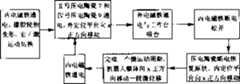
为了克服已有的宏/微双驱动方式在微驱动时存在运动耦合的缺陷,提供一种微驱动全解耦的机器人移动定位平台。本发明的技术方案如下:一种微驱动全解耦的宏/微双驱动微小型机器人移动定位平台,它包括宏运动机构,它还包括外定位平台1、内定位平台2、过渡平台3、外电磁铁4、内电磁铁5、I号压电陶瓷6、II号压电陶瓷7、III号压电陶瓷8、IV号压电陶瓷9、V号压电陶瓷10和VI号压电陶瓷11,外定位平台1与过渡平台3之间开有外圈柔性铰链槽12,过渡平台3与内定位平台2之间开有内圈柔性铰链槽13,外电磁铁4设置在外定位平台1上,内电磁铁5设置在内定位平台2上的中间处,I号压电陶瓷6、II号压电陶瓷7、III号压电陶瓷8和IV号压电陶瓷9设置在外定位平台1和过渡平台3之间,I号压电陶瓷6和III号压电陶瓷8具有纵向伸长方向并且横向对称设置在过渡平台3两边,II号压电陶瓷7和IV号压电陶瓷9具有横向伸长方向并且纵向对称设置在过渡平台3两边,V号压电陶瓷10和VI号压电陶瓷11设置在过渡平台3和内定位平台2之间,V号压电陶瓷10和VI号压电陶瓷11的伸长方向互相平行并且对称于内电磁铁5。在大范围内,机器人采用快速宏运动来逼近目标,当机器人运动到接近目标位置时,运动方式由快速宏运动切换到微运动模式,来实现机器人的精密定位。首先电机停止转动,外(或内)电磁铁通电与铁磁性工作台吸合,橡胶轮胎产生变形,完成宏/微运动切换。压电陶瓷与电磁铁配合,根据尺蠖蠕动原理,对机器人进行小范围内的微动调整,可以实现对机器人移动定位平台的高精密定位。微运动的运动控制如图1所示,其运动方式如下:a)II号压电陶瓷7和IV号压电陶瓷9同时伸长相同的长度,机器人定位平台沿横向移动一段微位移;b)I号压电陶瓷6和III号压电陶瓷8同时伸长相同的长度,机器人定位平台沿纵向移动一段微位移;c)V号压电陶瓷10和VI号压电陶瓷11同时伸长相同的长度,机器人定位平台以其中心为轴转动一个角度;机器人定位平台微动时,可实现纵、横方向的直线运动以及转动,具有三个自由度,运动的方向由内外电磁铁的通电顺序来决定。由于本发明的移动定位平台在微动时其纵向运动、横向运动以及旋转都能独立地实现其各自精确地座标运动,微运动在纵和横方向上完全解耦,简化了理论模型与控制电路。本发明既可以在大范围内实现快速移动,又可以在小范围内实现高精度的位置调整,具有较大的推广价值。In order to overcome the defect of kinematic coupling in the micro-drive of the existing macro/micro dual drive mode, a robot mobile positioning platform with fully decoupled micro-drive is provided. The technical scheme of the present invention is as follows: a macro/micro dual-drive micro-robot mobile positioning platform with fully decoupled micro-drive, which includes a macro-motion mechanism, and it also includes an outer positioning platform 1, an inner positioning platform 2, a transition platform 3, Outer electromagnet 4, inner electromagnet 5, No. I piezoelectric ceramic 6, No. II piezoelectric ceramic 7, No. III piezoelectric ceramic 8, No. IV piezoelectric ceramic 9, No. V piezoelectric ceramic 10 and No. VI piezoelectric ceramic 11 There is an outer flexible hinge groove 12 between the outer positioning platform 1 and the transition platform 3, an inner flexible hinge groove 13 is opened between the transition platform 3 and the inner positioning platform 2, the outer electromagnet 4 is arranged on the outer positioning platform 1, and the inner The electromagnet 5 is arranged in the middle of the inner positioning platform 2, and No. I piezoelectric ceramics 6, No. II piezoelectric ceramics 7, No. III piezoelectric ceramics 8, and No. IV piezoelectric ceramics 9 are arranged on the outer positioning platform 1 and the transition platform 3 Among them, No. I piezoelectric ceramics 6 and No. III piezoelectric ceramics 8 have a longitudinal elongation direction and are symmetrically arranged on both sides of the transition platform 3, and No. II piezoelectric ceramics 7 and IV No. piezoelectric ceramics 9 have a transverse elongation direction and Longitudinally symmetrically arranged on both sides of the transition platform 3, No. V piezoelectric ceramics 10 and No. VI piezoelectric ceramics 11 are arranged between the transition platform 3 and the inner positioning platform 2, and the extension of the No. V piezoelectric ceramics 10 and No. VI piezoelectric ceramics 11 The long directions are parallel to each other and symmetrical to the inner electromagnet 5 . In a large range, the robot uses fast macro motion to approach the target. When the robot moves close to the target position, the motion mode is switched from fast macro motion to micro motion mode to achieve precise positioning of the robot. Firstly, the motor stops rotating, and the outer (or inner) electromagnet is energized to attract the ferromagnetic workbench, the rubber tire is deformed, and the macro/micro motion switching is completed. Piezoelectric ceramics are combined with electromagnets to fine-tune the robot in a small range according to the principle of inchworm creep, which can realize high-precision positioning of the robot's mobile positioning platform. The motion control of the micro-motion is shown in Figure 1, and its motion mode is as follows: a) No. II piezoelectric ceramic 7 and No. IV piezoelectric ceramic 9 elongate the same length at the same time, and the robot positioning platform moves a small displacement along the lateral direction; b) No. I piezoceramics 6 and No. III piezoceramics 8 are elongated by the same length at the same time, and the positioning platform of the robot moves longitudinally for a small displacement; c) No. V piezoceramics 10 and No. VI piezoceramics 11 elongate the same length at the same time Length, the robot positioning platform rotates an angle with its center as the axis; when the robot positioning platform moves slightly, it can realize linear motion and rotation in the vertical and horizontal directions, with three degrees of freedom, and the direction of motion is determined by the energization sequence of the inner and outer electromagnets. Decide. Since the vertical movement, lateral movement and rotation of the mobile positioning platform of the present invention can independently realize their respective precise coordinate movements during micro-motion, the micro-motion is completely decoupled in the vertical and horizontal directions, which simplifies the theoretical model and control circuit. The invention can not only realize rapid movement in a large range, but also realize high-precision position adjustment in a small range, and has great popularization value.
附图说明:Description of drawings:
图1是本发明的结构示意图,图2-图4是本发明微动控制的顺序框图,图5是图1的A向视图,图6是本发明实施方式四的结构示意图。Fig. 1 is a schematic structural diagram of the present invention, Fig. 2-Fig. 4 is a sequential block diagram of the micro-motion control of the present invention, Fig. 5 is a view along the direction A of Fig. 1 , and Fig. 6 is a schematic structural diagram of Embodiment 4 of the present invention.
具体实施方式:Detailed ways:
具体实施方式一:下面结合图1和图5具体说明本实施方式。它由宏运动机构、外定位平台1、内定位平台2、过渡平台3、外电磁铁4、内电磁铁5、I号压电陶瓷6、II号压电陶瓷7、III号压电陶瓷8、IV号压电陶瓷9、V号压电陶瓷10、VI号压电陶瓷11组成,外定位平台1与过渡平台3之间开有外圈柔性铰链槽12,过渡平台3与内定位平台2之间开有内圈柔性铰链槽13,外电磁铁4设置在外定位平台1上,内电磁铁5设置在内定位平台2上的中间处,I号压电陶瓷6、II号压电陶瓷7、III号压电陶瓷8和IV号压电陶瓷9设置在外定位平台1和过渡平台3之间,I号压电陶瓷6和III号压电陶瓷8具有纵向伸长方向并且横向对称设置在过渡平台3两边,II号压电陶瓷7和IV号压电陶瓷9具有横向伸长方向并且纵向对称设置在过渡平台3两边,V号压电陶瓷10和VI号压电陶瓷11设置在过渡平台3和内定位平台2之间,V号压电陶瓷10和VI号压电陶瓷11的伸长方向互相平行并且对称于内电磁铁5。图2至图4给出了微动动作的实现方式和工作的顺序,其中X正方向代表横向运动的一个方向,-X方向代表横向运动的另一个方向,纵向运动与横向运动的原理是相同的。Specific implementation mode 1: This implementation mode will be specifically described below with reference to FIG. 1 and FIG. 5 . It consists of macro motion mechanism, outer positioning platform 1, inner positioning platform 2, transition platform 3, outer electromagnet 4, inner electromagnet 5, I piezoelectric ceramic 6, II piezoelectric ceramic 7, III piezoelectric ceramic 8, Composed of No. IV piezoelectric ceramic 9, No. V piezoelectric ceramic 10, and No. VI piezoelectric ceramic 11, there is an outer ring flexible hinge groove 12 between the outer positioning platform 1 and the transition platform 3, and the transition platform 3 and the inner positioning platform 2 There is an inner ring flexible hinge groove 13 between them, the outer electromagnet 4 is arranged on the outer positioning platform 1, the inner electromagnet 5 is arranged in the middle of the inner positioning platform 2, and No. I piezoelectric ceramics 6, No. II piezoelectric ceramics 7, III No. 8 piezoelectric ceramics and No. IV piezoelectric ceramics 9 are arranged between the outer positioning platform 1 and the transition platform 3, and No. I piezoelectric ceramics 6 and No. III piezoelectric ceramics 8 have longitudinal elongation directions and are laterally symmetrically arranged on the transition platform 3 On both sides, No. II piezoelectric ceramics 7 and No. IV piezoelectric ceramics 9 have transverse elongation directions and are longitudinally symmetrically arranged on both sides of the transition platform 3, and No. V piezoelectric ceramics 10 and No. VI piezoelectric ceramics 11 are arranged on the transition platform 3 and the inner Between the positioning platforms 2 , the extension directions of the No. V piezoelectric ceramic 10 and the No. VI piezoelectric ceramic 11 are parallel to each other and symmetrical to the inner electromagnet 5 . Figure 2 to Figure 4 show the realization of the micro-movement and the sequence of work, where the positive X direction represents one direction of lateral movement, and the -X direction represents the other direction of lateral movement, and the principle of longitudinal movement and lateral movement is the same of.
具体实施方式二:下面结合图1和图5具体说明本实施方式。本实施方式与实施方式一的不同点是,宏运动机构由两个主动轮23、两个从动轮14、电机15-1和电机15-2组成,两个主动轮23分别设置在外定位平台1的一组对角处,两个从动轮14分别设置在外定位平台1的另一组对角处,电机15-1和电机15-2给主动轮23提供旋转动力。两个主动轮23和两个从动轮14的轮缘外表面都是橡胶材质。如此设置,当电磁铁得电后与铁磁性工作台相吸引时,橡胶变形,使外定位平台1或内定位平台2不移动位置。该微小型机器人移动定位平台共有如下4种宏运动方式:a)直线前进与后退:电机15-1、电机15-2保持相同的转速同时向前/向后转动;b)前向左右转弯:保持电机15-1、电机15-2以不同的转速同时向前转动;c)后向左右转弯:保持电机15-1、电机15-2以不同的转速同时向后转动;d)零半径圆周运动:电机15-1、电机15-2保持相同的转速,相反的方向同时转动。其它组成和连接关系与实施方式一相同。Specific Embodiment 2: The present embodiment will be specifically described below with reference to FIG. 1 and FIG. 5 . The difference between this embodiment and Embodiment 1 is that the macro motion mechanism is composed of two driving wheels 23, two driven wheels 14, a motor 15-1 and a motor 15-2, and the two driving wheels 23 are respectively arranged on the outer positioning platform 1 Two driven wheels 14 are respectively arranged at another group of diagonal corners of the outer positioning platform 1, and the motor 15-1 and the motor 15-2 provide rotational power to the driving wheel 23. The rim outer surfaces of the two driving wheels 23 and the two driven wheels 14 are made of rubber. With such arrangement, when the electromagnet is electrified and attracted to the ferromagnetic workbench, the rubber is deformed so that the outer positioning platform 1 or the inner positioning platform 2 does not move. The micro-robot mobile positioning platform has the following four macro-motion modes: a) straight forward and backward: motor 15-1 and motor 15-2 keep the same speed and rotate forward/backward at the same time; b) turn forward to left and right: Keep the motor 15-1 and the motor 15-2 rotating forward at the same time at different speeds; c) turn left and right behind: keep the motor 15-1 and the motor 15-2 turning backward at the same time at different speeds; d) zero-radius circle Movement: the motor 15-1 and the motor 15-2 maintain the same rotational speed, and rotate in opposite directions simultaneously. Other components and connections are the same as those in Embodiment 1.
具体实施方式三:下面结合图1具体说明本实施方式。本实施方式与实施方式一的不同点是,它还包括四条条形柔性铰链槽16,条形柔性铰链槽16分别开在过渡平台3的四个框边上并且沿框边的长度方向设置。如此设置,能提高本发明平台微动时的变形移动能力,提高柔性。其它组成和连接关系与实施方式一相同。Specific Embodiment Three: The present embodiment will be specifically described below with reference to FIG. 1 . The difference between this embodiment and Embodiment 1 is that it also includes four strip-shaped flexible hinge slots 16, which are respectively opened on the four frame sides of the transition platform 3 and arranged along the length direction of the frame sides. Such setting can improve the deformation and movement ability of the platform of the present invention when it moves slightly, and improve the flexibility. Other components and connections are the same as those in Embodiment 1.
具体实施方式四:下面结合图1和图6具体说明本实施方式。本实施方式与实施方式一的不同点是,V号压电陶瓷10或VI号压电陶瓷11的两侧面处的过渡平台3上开有月牙缺口17,月牙缺口17内设置弯曲弹簧18,弯曲弹簧18的两端连接在过渡平台3上。如此设置,提高了微动时旋转运动的旋转变形能力,而且弯曲弹簧18使内定位平台2与过渡平台3之间的弹性回位准确、快捷。其它组成和连接关系与实施方式一相同。Specific Embodiment 4: The present embodiment will be specifically described below with reference to FIG. 1 and FIG. 6 . The difference between this embodiment and Embodiment 1 is that there is a crescent notch 17 on the transition platform 3 at the two sides of the piezoelectric ceramic 10 or VI piezoelectric ceramic 11, and a bending spring 18 is arranged in the crescent notch 17. Both ends of the spring 18 are connected to the transition platform 3 . Such setting improves the rotational deformation ability of the rotational movement during micro-movement, and the bending spring 18 makes the elastic return between the inner positioning platform 2 and the transition platform 3 accurate and fast. Other components and connections are the same as those in Embodiment 1.
Claims (4)
Priority Applications (1)
| Application Number | Priority Date | Filing Date | Title |
|---|---|---|---|
| CNB2004100437594ACN1305644C (en) | 2004-07-30 | 2004-07-30 | Microdriving fully decoupled macrol/micre bidriving minitype robot moving locating platform |
Applications Claiming Priority (1)
| Application Number | Priority Date | Filing Date | Title |
|---|---|---|---|
| CNB2004100437594ACN1305644C (en) | 2004-07-30 | 2004-07-30 | Microdriving fully decoupled macrol/micre bidriving minitype robot moving locating platform |
Publications (2)
| Publication Number | Publication Date |
|---|---|
| CN1597268Atrue CN1597268A (en) | 2005-03-23 |
| CN1305644C CN1305644C (en) | 2007-03-21 |
Family
ID=34665431
Family Applications (1)
| Application Number | Title | Priority Date | Filing Date |
|---|---|---|---|
| CNB2004100437594AExpired - Fee RelatedCN1305644C (en) | 2004-07-30 | 2004-07-30 | Microdriving fully decoupled macrol/micre bidriving minitype robot moving locating platform |
Country Status (1)
| Country | Link |
|---|---|
| CN (1) | CN1305644C (en) |
Cited By (7)
| Publication number | Priority date | Publication date | Assignee | Title |
|---|---|---|---|---|
| CN100339194C (en)* | 2005-11-14 | 2007-09-26 | 哈尔滨工业大学 | Microminiature mobile robot system oriented to precise operation of micro electromechanical system |
| CN100357069C (en)* | 2005-11-10 | 2007-12-26 | 上海大学 | 2D shifting unit |
| CN102543217A (en)* | 2012-01-20 | 2012-07-04 | 澳门大学 | Macro-micro driven bidimensional integrated micro positioning platform |
| CN103557412A (en)* | 2013-11-06 | 2014-02-05 | 山东大学 | Bipolar two-dimensional fully flexible high-precision servo platform |
| CN105643592A (en)* | 2016-03-15 | 2016-06-08 | 河北工业大学 | Symmetrical decoupling and single degree of freedom flexible operation mechanism |
| CN109093598A (en)* | 2018-08-30 | 2018-12-28 | 上海大学 | A kind of freedom degree parallel connection micromotion platform |
| CN113548352A (en)* | 2021-06-04 | 2021-10-26 | 哈尔滨工业大学 | An integrated robot for library access to books |
Families Citing this family (1)
| Publication number | Priority date | Publication date | Assignee | Title |
|---|---|---|---|---|
| CN101947779B (en)* | 2010-09-01 | 2012-08-08 | 华南理工大学 | Structure of combination drive type micro robot |
Family Cites Families (5)
| Publication number | Priority date | Publication date | Assignee | Title |
|---|---|---|---|---|
| US5481184A (en)* | 1991-12-31 | 1996-01-02 | Sarcos Group | Movement actuator/sensor systems |
| CN1110122C (en)* | 1999-05-28 | 2003-05-28 | 清华大学 | Miniature monoblock precisive plane moving mechanism and device thereof |
| CN1086163C (en)* | 1999-09-30 | 2002-06-12 | 燕山大学 | Six-freedom parallel decoupling-structure jogging robot |
| CN2576434Y (en)* | 2002-11-18 | 2003-10-01 | 哈尔滨工业大学博实精密测控有限责任公司 | Six-freedom precision paralleled robot |
| CN1233509C (en)* | 2002-12-30 | 2005-12-28 | 上海交通大学 | Miniature creeping vehicle based on shape memory alloy driving |
- 2004
- 2004-07-30CNCNB2004100437594Apatent/CN1305644C/ennot_activeExpired - Fee Related
Cited By (10)
| Publication number | Priority date | Publication date | Assignee | Title |
|---|---|---|---|---|
| CN100357069C (en)* | 2005-11-10 | 2007-12-26 | 上海大学 | 2D shifting unit |
| CN100339194C (en)* | 2005-11-14 | 2007-09-26 | 哈尔滨工业大学 | Microminiature mobile robot system oriented to precise operation of micro electromechanical system |
| CN102543217A (en)* | 2012-01-20 | 2012-07-04 | 澳门大学 | Macro-micro driven bidimensional integrated micro positioning platform |
| CN102543217B (en)* | 2012-01-20 | 2013-10-23 | 澳门大学 | Macro-micro drive two-dimensional integrated micro-positioning platform |
| CN103557412A (en)* | 2013-11-06 | 2014-02-05 | 山东大学 | Bipolar two-dimensional fully flexible high-precision servo platform |
| CN103557412B (en)* | 2013-11-06 | 2015-12-02 | 山东大学 | Bipolar two-dimensional Grazing condition high-precision servo platform |
| CN105643592A (en)* | 2016-03-15 | 2016-06-08 | 河北工业大学 | Symmetrical decoupling and single degree of freedom flexible operation mechanism |
| CN109093598A (en)* | 2018-08-30 | 2018-12-28 | 上海大学 | A kind of freedom degree parallel connection micromotion platform |
| CN109093598B (en)* | 2018-08-30 | 2021-10-12 | 上海大学 | Three-degree-of-freedom parallel micro-motion platform |
| CN113548352A (en)* | 2021-06-04 | 2021-10-26 | 哈尔滨工业大学 | An integrated robot for library access to books |
Also Published As
| Publication number | Publication date |
|---|---|
| CN1305644C (en) | 2007-03-21 |
Similar Documents
| Publication | Publication Date | Title |
|---|---|---|
| CN108818495B (en) | Flexible robot based on piezoelectric drive and control method thereof | |
| CN1597268A (en) | Microdriving fully decoupled macrol/micre bidriving minitype robot moving locating platform | |
| Pelrine et al. | Methods and results for rotation of diamagnetic robots using translational designs | |
| CN105196280A (en) | Redundant drive type three-horizontal-movement micro-operation robot | |
| JP2004122271A (en) | Micromotion control method and micromotion stage | |
| CN109768733B (en) | Twice-rotation piezoelectric rotary driver | |
| CN1110122C (en) | Miniature monoblock precisive plane moving mechanism and device thereof | |
| JP2010201606A (en) | Conveyer | |
| CN103950027A (en) | Linear supersonic motor-based two-finger parallel connection micro operation hand and operation method | |
| CN207801784U (en) | A kind of branched two-way piezoelectric rotary driver of support | |
| CN106849746B (en) | Three-degree-of-freedom piezoelectric drive platform based on inertia impact | |
| CN108092548A (en) | A kind of two-way piezoelectric rotary driver | |
| CN113511315B (en) | A ray type underwater piezoelectric robot | |
| Kortschack et al. | Driving principles of mobile microrobots for micro-and nanohandling | |
| US9876444B2 (en) | Wobble motor with a solid state actuator | |
| CN108063564A (en) | A kind of novel friction type linear piezoelectric actuator | |
| CN206686103U (en) | Three-degree-of-freedom piezoelectric drive platform based on inertia impact | |
| CN207801782U (en) | A kind of multiple pressure electric tachometer indicator bidirectional rotation driver | |
| CN1261346C (en) | Running fix platform for macro/micro dual driven miniature type robot | |
| KR100609884B1 (en) | 3 degrees of freedom microdisplacement drive | |
| CN117277866B (en) | Four-degree-of-freedom trans-scale stepping actuator based on piezoelectric driving | |
| CN108054949B (en) | Multi-piezoelectric vibrator bidirectional rotary driver | |
| CN118952250B (en) | Ultrasonic stick-slip dual-mode alternating macro-micro piezoelectric robot and control method | |
| CN112318549B (en) | Two-degree-of-freedom high-rigidity robot | |
| Ikegami et al. | Motion analysis of a micro-actuator using three piezoelectric actuators |
Legal Events
| Date | Code | Title | Description |
|---|---|---|---|
| C06 | Publication | ||
| PB01 | Publication | ||
| C10 | Entry into substantive examination | ||
| SE01 | Entry into force of request for substantive examination | ||
| C14 | Grant of patent or utility model | ||
| GR01 | Patent grant | ||
| C17 | Cessation of patent right | ||
| CF01 | Termination of patent right due to non-payment of annual fee | Granted publication date:20070321 Termination date:20110730 |