CN1585565A - Loudspeaker - Google Patents
LoudspeakerDownload PDFInfo
- Publication number
- CN1585565A CN1585565ACNA200410064218XACN200410064218ACN1585565ACN 1585565 ACN1585565 ACN 1585565ACN A200410064218X ACNA200410064218X ACN A200410064218XACN 200410064218 ACN200410064218 ACN 200410064218ACN 1585565 ACN1585565 ACN 1585565A
- Authority
- CN
- China
- Prior art keywords
- voice coil
- vibrating membrane
- groove
- section
- speaker
- Prior art date
- Legal status (The legal status is an assumption and is not a legal conclusion. Google has not performed a legal analysis and makes no representation as to the accuracy of the status listed.)
- Granted
Links
Images


Classifications
- H—ELECTRICITY
- H04—ELECTRIC COMMUNICATION TECHNIQUE
- H04R—LOUDSPEAKERS, MICROPHONES, GRAMOPHONE PICK-UPS OR LIKE ACOUSTIC ELECTROMECHANICAL TRANSDUCERS; DEAF-AID SETS; PUBLIC ADDRESS SYSTEMS
- H04R9/00—Transducers of moving-coil, moving-strip, or moving-wire type
- H04R9/02—Details
- H—ELECTRICITY
- H04—ELECTRIC COMMUNICATION TECHNIQUE
- H04R—LOUDSPEAKERS, MICROPHONES, GRAMOPHONE PICK-UPS OR LIKE ACOUSTIC ELECTROMECHANICAL TRANSDUCERS; DEAF-AID SETS; PUBLIC ADDRESS SYSTEMS
- H04R9/00—Transducers of moving-coil, moving-strip, or moving-wire type
- H04R9/02—Details
- H04R9/04—Construction, mounting, or centering of coil
- H—ELECTRICITY
- H04—ELECTRIC COMMUNICATION TECHNIQUE
- H04R—LOUDSPEAKERS, MICROPHONES, GRAMOPHONE PICK-UPS OR LIKE ACOUSTIC ELECTROMECHANICAL TRANSDUCERS; DEAF-AID SETS; PUBLIC ADDRESS SYSTEMS
- H04R1/00—Details of transducers, loudspeakers or microphones
- H—ELECTRICITY
- H04—ELECTRIC COMMUNICATION TECHNIQUE
- H04R—LOUDSPEAKERS, MICROPHONES, GRAMOPHONE PICK-UPS OR LIKE ACOUSTIC ELECTROMECHANICAL TRANSDUCERS; DEAF-AID SETS; PUBLIC ADDRESS SYSTEMS
- H04R7/00—Diaphragms for electromechanical transducers; Cones
- H04R7/02—Diaphragms for electromechanical transducers; Cones characterised by the construction
- H04R7/04—Plane diaphragms
- H—ELECTRICITY
- H04—ELECTRIC COMMUNICATION TECHNIQUE
- H04R—LOUDSPEAKERS, MICROPHONES, GRAMOPHONE PICK-UPS OR LIKE ACOUSTIC ELECTROMECHANICAL TRANSDUCERS; DEAF-AID SETS; PUBLIC ADDRESS SYSTEMS
- H04R9/00—Transducers of moving-coil, moving-strip, or moving-wire type
- H04R9/02—Details
- H04R9/04—Construction, mounting, or centering of coil
- H04R9/045—Mounting
- H—ELECTRICITY
- H04—ELECTRIC COMMUNICATION TECHNIQUE
- H04R—LOUDSPEAKERS, MICROPHONES, GRAMOPHONE PICK-UPS OR LIKE ACOUSTIC ELECTROMECHANICAL TRANSDUCERS; DEAF-AID SETS; PUBLIC ADDRESS SYSTEMS
- H04R9/00—Transducers of moving-coil, moving-strip, or moving-wire type
- H04R9/06—Loudspeakers
- H—ELECTRICITY
- H04—ELECTRIC COMMUNICATION TECHNIQUE
- H04R—LOUDSPEAKERS, MICROPHONES, GRAMOPHONE PICK-UPS OR LIKE ACOUSTIC ELECTROMECHANICAL TRANSDUCERS; DEAF-AID SETS; PUBLIC ADDRESS SYSTEMS
- H04R2307/00—Details of diaphragms or cones for electromechanical transducers, their suspension or their manufacture covered by H04R7/00 or H04R31/003, not provided for in any of its subgroups
- H04R2307/021—Diaphragms comprising cellulose-like materials, e.g. wood, paper, linen
- H—ELECTRICITY
- H04—ELECTRIC COMMUNICATION TECHNIQUE
- H04R—LOUDSPEAKERS, MICROPHONES, GRAMOPHONE PICK-UPS OR LIKE ACOUSTIC ELECTROMECHANICAL TRANSDUCERS; DEAF-AID SETS; PUBLIC ADDRESS SYSTEMS
- H04R2307/00—Details of diaphragms or cones for electromechanical transducers, their suspension or their manufacture covered by H04R7/00 or H04R31/003, not provided for in any of its subgroups
- H04R2307/025—Diaphragms comprising polymeric materials
Landscapes
- Engineering & Computer Science (AREA)
- Physics & Mathematics (AREA)
- Acoustics & Sound (AREA)
- Signal Processing (AREA)
- Multimedia (AREA)
- Diaphragms For Electromechanical Transducers (AREA)
- Audible-Bandwidth Dynamoelectric Transducers Other Than Pickups (AREA)
- Chair Legs, Seat Parts, And Backrests (AREA)
- Liquid Crystal (AREA)
- Surgical Instruments (AREA)
Abstract
Description
Translated fromChinese发明领域field of invention
本发明涉及扬声器,更具体地说,涉及用于各种类型的音频设备,例如音视频设备的扬声器。The present invention relates to loudspeakers and, more particularly, to loudspeakers for various types of audio equipment, such as audio-visual equipment.
发明背景Background of the invention
一般地,音视频设备如电视机的结构中的扬声器位于阴极射线管相对的两侧。因此,作为音视频设备中所用扬声器,其结构采用拉长形,如矩形状、椭圆形等。近年来,由于显示屏变得更宽,要求用在音视频设备中的扬声器更狭小一些,还要更薄一些,以便适用于比较薄的设备,如液晶显示器或等离子体显示器。Generally, audio-visual equipment such as televisions are constructed with speakers located on opposite sides of a cathode ray tube. Therefore, as a speaker used in audio and video equipment, its structure adopts an elongated shape, such as a rectangular shape, an oval shape, and the like. In recent years, as display screens have become wider, speakers used in audio-visual equipment have been required to be smaller and thinner in order to accommodate thinner devices such as liquid crystal displays or plasma displays.
这里,具有长形结构的常规扬声器将结合图17-19介绍。图17是具有长形结构的常规扬声器的俯视图,图18是扬声器沿长轴方向的截面图,图19是扬声器沿短轴方向的截面图。图17-19中,产生空气振动的振动膜1是长形的,振动膜1的周边部分通过边缘2支撑在一个支架3上。音圈4固定在振动膜1的平面部分上。Here, a conventional loudspeaker having an elongated structure will be described with reference to FIGS. 17-19. Fig. 17 is a plan view of a conventional speaker having an elongated structure, Fig. 18 is a sectional view of the speaker along the major axis, and Fig. 19 is a sectional view of the speaker along the minor axis. In FIGS. 17-19 , the
支架3中心部位有一个磁路8,包含磁轭5、磁铁6和顶板7。在图19中,磁铁6沿垂直于振动膜1的方向(即图19中箭头Z所指方向)磁化。相应地,磁隙9在磁轭5的开口(靠近边缘2)和顶板7之间形成,磁通量在此磁隙中沿垂直于振动膜1的方向产生。音圈4位于磁隙9之内,方向垂直于磁通量(即垂直于图19中平板的方向)。因此,如果音圈4中通交流电,振动膜1就会沿垂直于图19中箭头Z所示方向振动,从而向空间发射声波。There is a magnetic circuit 8 at the center of the support 3 , including a
在常规扬声器中,音圈是利用胶粘剂粘合在振动膜的平面部分的。音圈的每根线都具有圆截面,因此音圈与振动膜之间的接触面积很小。另外,胶粘剂容易散布到振动膜上的薄片中,从而使胶粘剂形成的胶粘剂层变薄。由于接触面积小,胶粘剂层又薄,音圈与振动膜之间的粘结强度小。因此,振动膜与音圈容易彼此分离,结果增加了振动膜在振动过程中的变形,或者使振动不充分。In a conventional loudspeaker, the voice coil is glued to the flat part of the diaphragm. Each wire of the voice coil has a circular cross section, so the contact area between the voice coil and the diaphragm is very small. In addition, the adhesive tends to spread into the sheet on the vibrating membrane, thereby thinning the adhesive layer formed by the adhesive. Due to the small contact area and the thin adhesive layer, the bonding strength between the voice coil and the diaphragm is small. Therefore, the vibrating membrane and the voice coil are easily separated from each other, resulting in increased deformation of the vibrating membrane during vibration, or insufficient vibration.
请注意到,特别是在具有长形结构的扬声器中,振动膜在振动过程中容易变形,因此需要增加振动膜与音圈之间的粘结强度。此外,在具有水平伸长截面的音圈中(即,如果振动膜的振动方向是垂直方向,则音圈截面在垂直方向短,而在水平方向长),如果音圈与振动膜之间的粘结强度小,音圈导线可能因振动膜的振动而彼此分离。如果音圈导线彼此分离,则声音的产生质量下降。Note that especially in speakers with elongated structures, the diaphragm is easily deformed during vibration, so it is necessary to increase the bonding strength between the diaphragm and the voice coil. Furthermore, in a voice coil with a horizontally elongated section (i.e., if the vibration direction of the diaphragm is vertical, the cross section of the voice coil is short in the vertical direction and long in the horizontal direction), if the distance between the voice coil and the diaphragm The bonding strength is small, and the voice coil wires may be separated from each other due to the vibration of the diaphragm. If the voice coil wires are separated from each other, the quality of sound production is degraded.
本发明概述SUMMARY OF THE INVENTION
因此,本发明的一个目标是提供可提高振动膜与音圈之间粘结强度的具有伸长结构的扬声器。Accordingly, an object of the present invention is to provide a loudspeaker having an elongated structure that can increase the bonding strength between a diaphragm and a voice coil.
为实现上述目标,本发明具有如下特征。本发明一方面涉及包含振动膜、边缘和音圈的扬声器。所述振动膜包含具有凹截面的凹槽。另外,振动膜具有水平或垂直伸长的形状。所述边缘的截面大致呈半圆形,与振动膜的外周缘相连接。所述音圈粘结到凹槽上。这里,音圈厚度要比凹槽深度大。此外,在音圈截面中,沿振动膜平面方向的尺寸要比垂直于振动膜平面方向的尺寸长。To achieve the above objects, the present invention has the following features. One aspect of the invention relates to a loudspeaker comprising a diaphragm, a lip and a voice coil. The vibrating membrane includes a groove having a concave cross-section. In addition, the diaphragm has a horizontally or vertically elongated shape. The cross-section of the edge is roughly semicircular, and is connected with the outer peripheral edge of the vibrating membrane. The voice coil is bonded to the groove. Here, the voice coil thickness is greater than the groove depth. In addition, in the cross-section of the voice coil, the dimension along the plane of the diaphragm is longer than the dimension perpendicular to the plane of the diaphragm.
请注意,可以施加胶粘剂将音圈粘结在振动膜上,形成覆盖音圈侧面的粘合带。Note that adhesive can be applied to bond the voice coil to the diaphragm, forming an adhesive strip that covers the sides of the voice coil.
另外,可以在粘结于音圈的凹槽粘结表面上形成许多突起,每个突起小于音圈导线的直径。In addition, a plurality of protrusions each smaller than the diameter of the voice coil wire may be formed on the bonding surface of the groove bonded to the voice coil.
本发明第二方面涉及包含振动膜、边缘、音圈和一个膜的扬声器。所述振动膜包含具有凹截面的凹槽。另外,振动膜具有水平或垂直伸长的形状。所述边缘的截面大致呈半圆形,与振动膜的外周缘相连接。所述音圈粘结到凹槽上。所述膜固定在振动膜和音圈上,从而在与振动膜粘结面相背的一面覆盖音圈。A second aspect of the invention relates to a loudspeaker comprising a diaphragm, a lip, a voice coil and a membrane. The vibrating membrane includes a groove having a concave cross-section. In addition, the diaphragm has a horizontally or vertically elongated shape. The cross-section of the edge is roughly semicircular, and is connected with the outer peripheral edge of the vibrating membrane. The voice coil is bonded to the groove. The membrane is secured to the vibrating membrane and the voice coil so as to cover the voice coil on the side opposite to the bonding side of the vibrating membrane.
请注意,所述膜可由聚合物膜、表面上蒸镀了金属箔的聚合物膜和金属箔等中任何一种物质制备。Note that the film may be prepared from any of a polymer film, a polymer film on which a metal foil is vapor-deposited, a metal foil, and the like.
此外,所述膜可由粘弹性材料制备。Additionally, the membranes can be prepared from viscoelastic materials.
本发明第三方面涉及包含振动膜、边缘、衬垫材料和音圈的扬声器。所述振动膜包含具有凹截面的凹槽。另外,振动膜具有水平或垂直伸长的形状。所述边缘的截面大致呈半圆形,与振动膜的外周缘相连接。所述衬垫材料粘结于凹槽上,具有平面形状。所述音圈通过衬垫材料粘结到凹槽上。A third aspect of the invention relates to a loudspeaker comprising a diaphragm, a lip, a gasket material and a voice coil. The vibrating membrane includes a groove having a concave cross-section. In addition, the diaphragm has a horizontally or vertically elongated shape. The cross-section of the edge is roughly semicircular, and is connected with the outer peripheral edge of the vibrating membrane. The gasket material is bonded to the groove and has a planar shape. The voice coil is bonded to the groove by a gasket material.
请注意,振动膜纵向截面可以是弧形,比边缘低。Note that the diaphragm longitudinal section can be curved, lower than the edge.
在第一个方面,将音圈粘结在振动膜上的胶粘剂保留在凹槽中,因而音圈与振动膜可通过足够厚的胶粘剂粘结在一起。因此,与常规结构相比,这样有可能提高音圈与振动膜之间的粘结强度,由此提高扬声器声音复制的质量。同样在第一个方面,由于音圈粘结在振动膜上形成水平伸长形状,有可能缩小扬声器的厚度,同时提高声音复制的质量。此外,在第一个方面,在将振动膜与音圈粘结在一起时,有可能对它们施加足够的压力。相应地,有可能将振动膜与音圈更紧密地粘结在一起。还是在第一个方面,凹槽增加了振动膜的刚性,因而有可能增加振动膜的高范围共振频率,因此有可能为扬声器提供高复制特征。In the first aspect, the adhesive bonding the voice coil to the diaphragm remains in the groove so that the voice coil and diaphragm can be bonded together with a sufficiently thick adhesive. Therefore, it is possible to increase the bonding strength between the voice coil and the diaphragm, thereby improving the quality of sound reproduction of the speaker, compared with the conventional structure. Also in the first aspect, since the voice coil is bonded to the diaphragm to form a horizontally elongated shape, it is possible to reduce the thickness of the speaker while improving the quality of sound reproduction. Furthermore, in the first aspect, it is possible to apply sufficient pressure on the diaphragm and voice coil when bonding them together. Accordingly, it is possible to bond the diaphragm and voice coil more closely together. Also in the first aspect, the grooves increase the rigidity of the diaphragm, thus making it possible to increase the high-range resonant frequencies of the diaphragm, thus making it possible to provide a loudspeaker with high reproduction characteristics.
另外,如果施加胶粘剂将音圈粘结到振动膜上,形成覆盖音圈侧面的粘合带,则有可能进一步提高音圈与振动膜之间的粘结强度。In addition, if an adhesive is applied to bond the voice coil to the diaphragm to form an adhesive tape covering the sides of the voice coil, it is possible to further increase the bonding strength between the voice coil and the diaphragm.
另外,在第二个方面,如同在第一个方面那样,由于振动膜的结构中包含凹槽,有可能提高音圈与振动膜之间的粘结强度,从而提高扬声器声音复制的质量。此外,通过将音圈夹在振动膜和膜之间,有可能提高音圈与振动膜之间的粘结强度。Also, in the second aspect, as in the first aspect, since the grooves are included in the structure of the diaphragm, it is possible to increase the bonding strength between the voice coil and the diaphragm, thereby improving the quality of sound reproduction of the speaker. In addition, by sandwiching the voice coil between the diaphragm and the diaphragm, it is possible to increase the bonding strength between the voice coil and the diaphragm.
同样,如果所述膜是金属箔或蒸镀了金属箔的聚合物膜,膜的导热效应将减小音圈温度的增加幅度。因此,有可能获得利用更大的输入功率工作的扬声器。Likewise, if the film is a metal foil or a polymer film on which a metal foil has been evaporated, the thermal conductivity of the film will reduce the increase in voice coil temperature. Therefore, it is possible to obtain loudspeakers that operate with greater input power.
此外,如果所述膜由粘弹性材料制备,则膜的内部损耗将防止音圈的不必要振动。因此,有可能进一步减少振动膜在振动过程中的变形。Furthermore, if the membrane is made of a viscoelastic material, the internal losses of the membrane will prevent unwanted vibrations of the voice coil. Therefore, it is possible to further reduce deformation of the diaphragm during vibration.
此外,在第三个方面,如同在第一个方面中那样,由于振动膜的结构中包含凹槽,有可能提高音圈与振动膜之间的粘结强度,从而提高扬声器声音复制的质量。此外,在振动膜与音圈之间存在衬垫材料,因而衬垫材料的内部损耗将防止音圈不必要的共振,从而提高了扬声器声音复制的质量。Furthermore, in the third aspect, as in the first aspect, since the groove is included in the structure of the diaphragm, it is possible to increase the bonding strength between the voice coil and the diaphragm, thereby improving the quality of sound reproduction of the speaker. In addition, there is a spacer material between the diaphragm and the voice coil, so the internal loss of the spacer material will prevent unwanted resonance of the voice coil, thereby improving the quality of sound reproduction of the loudspeaker.
此外,如果振动膜形成弧形截面,则与振动膜形成直线截面相比,有可能提高振动膜的刚性。相应地,有可能提高振动膜的高范围共振频率。因此,有可能为扬声器提供高复制特征。In addition, if the vibrating film is formed in an arcuate cross section, it is possible to increase the rigidity of the vibrating film compared with that in which the vibrating film is formed in a linear cross section. Accordingly, it is possible to increase the high-range resonance frequency of the diaphragm. Therefore, it is possible to provide a loudspeaker with high reproduction characteristics.
通过以下结合附图对本发明更详细的描述,我们将更清楚地看到本发明的上述及其他目标、特征、要点和优点。Through the following more detailed description of the present invention in conjunction with the accompanying drawings, we will more clearly see the above and other objectives, features, main points and advantages of the present invention.
附图简介Brief introduction to the drawings
图1是第一个实施方式中扬声器的俯视图;Fig. 1 is the top view of loudspeaker in the first embodiment;
图2是第一个实施方式中扬声器沿长轴方向的截面图;Fig. 2 is a sectional view along the long axis direction of the loudspeaker in the first embodiment;
图3是第一个实施方式中扬声器沿短轴方向的截面图;Fig. 3 is a sectional view along the short axis direction of the speaker in the first embodiment;
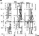
图4A是常规扬声器的声压频率特征图;Fig. 4A is the sound pressure frequency characteristic figure of conventional loudspeaker;
图4B是第一个实施方式中扬声器的声压频率特征图;Fig. 4B is a sound pressure frequency characteristic diagram of the loudspeaker in the first embodiment;
图5是第二个实施方式中扬声器沿短轴方向的截面图;Fig. 5 is a sectional view along the short axis direction of the speaker in the second embodiment;
图6是第三个实施方式中扬声器的俯视图;Fig. 6 is a top view of the speaker in the third embodiment;
图7是第三个实施方式中扬声器沿短轴方向的截面图;Fig. 7 is a sectional view along the short axis direction of the speaker in the third embodiment;
图8是第三个实施方式中扬声器变体的俯视图;Figure 8 is a top view of a speaker variant in a third embodiment;
图9是第四个实施方式中扬声器沿短轴方向的截面图;Fig. 9 is a cross-sectional view of the speaker along the minor axis in the fourth embodiment;
图10是第四个实施方式中扬声器的变体沿短轴方向的截面图;Fig. 10 is a sectional view along the minor axis direction of a variation of the loudspeaker in the fourth embodiment;
图11是第五个实施方式中扬声器沿短轴方向的截面图;Fig. 11 is a cross-sectional view of the speaker along the minor axis in the fifth embodiment;
图12是第五个实施方式中扬声器的变体沿短轴方向的截面图;Fig. 12 is a cross-sectional view along the minor axis of a variant of the speaker in the fifth embodiment;
图13是第六个实施方式中扬声器沿短轴方向的截面图;Fig. 13 is a cross-sectional view of the speaker along the minor axis in the sixth embodiment;
图14是第七个实施方式中扬声器的俯视图;Fig. 14 is a top view of the speaker in the seventh embodiment;
图15是第七个实施方式中扬声器沿长轴方向的截面图;Fig. 15 is a cross-sectional view of the loudspeaker along the long axis in the seventh embodiment;
图16是第七个实施方式中扬声器沿短轴方向的截面图;Fig. 16 is a sectional view along the minor axis of the speaker in the seventh embodiment;
图17是具有拉长结构的常规扬声器的俯视图;17 is a top view of a conventional loudspeaker with an elongated structure;
图18是具有拉长结构的常规扬声器沿长轴方向的截面图;Fig. 18 is a sectional view along the long axis direction of a conventional loudspeaker having an elongated structure;
图19是具有拉长结构的常规扬声器沿短轴方向的截面图。Fig. 19 is a sectional view along the minor axis of a conventional speaker having an elongated structure.
本发明优选实施方式Preferred Embodiments of the Invention
实施方式1
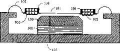
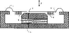
下面介绍本发明第一个实施方式中的扬声器。图1是扬声器的俯视图,图2是所述扬声器沿长轴方向的截面图(A-B截面图),图3是所述扬声器沿短轴方向的截面图(C-D截面图)。图1-3中,所述扬声器包含振动膜101、边缘102、支架104、音圈105、磁轭107、磁铁108和顶板109。如图1所示,扬声器具有沿垂直(或水平)方向拉长的形状。请注意,在以下描述中,扬声器上安装振动膜101的一侧(图2中左侧)称作“上表面侧”,安装磁轭107的一侧(图2中右侧)称作“下表面侧”。此外,振动膜101的纵向称作“长轴方向”,它大致呈平面形状,而垂直于长轴的方向称作“短轴方向”。The speaker in the first embodiment of the present invention will be described below. Fig. 1 is a top view of the speaker, Fig. 2 is a sectional view of the speaker along the major axis (A-B sectional view), and Fig. 3 is a sectional view of the speaker along the short axis (C-D sectional view). In FIGS. 1-3 , the loudspeaker includes a
如图1-3所示,除了将随后介绍的凹槽部分103之外,振动膜101具有平面形状。振动膜101的形状在垂直(或水平)方向拉长。具体说,振动膜101的形状包含两个通过弧连接的平行面。振动膜101通过使薄刚性膜如聚亚酰胺材料成形获得,或者用又轻又很硬的纸质材料制备。边缘102沿振动膜101的外周边形成环形。边缘102有一个大致呈半圆形的截面。边缘102的外周边与支架104和磁轭107相连接。在此第一个实施方式中,边缘102沿长轴方向(图1中平板从顶到底的方向)的两个端部与支架104连接,边缘102沿长轴方向的中心部位与磁轭107连接。这样,振动膜101就通过边缘102支撑在支架104和磁轭107上。As shown in FIGS. 1-3 , the vibrating
此外如图2和3所示,支架104沿长轴方向的中央部位与磁轭107连接。磁铁108与磁轭107的上表面侧连接。而且,磁铁108与顶板109的上表面侧连接。磁轭107、磁铁108和顶板109形成磁路110。音圈105粘结到振动膜101上,从而位于磁路110形成的磁隙中。音圈105由许多电线的圈构成,电线是在铜或铝线上覆盖绝缘涂料制成的。在图1-3所示结构中,如果在音圈105中通交流电,音圈105中就会产生驱动力,使粘结在音圈105上的振动膜101产生振动,由此发出声音。In addition, as shown in FIGS. 2 and 3 , the central part of the
这里,在此第一个实施方式中,振动膜101具有含凹形截面的凹槽103(见图2和3)。音圈105通过胶粘剂106粘结到凹槽103凹面部分的底部。凹槽103形成环形,与音圈105的形状相适应。具体说来,在此第一个实施方式中,音圈105的形状从上表面侧看是沿长轴方向拉长的矩形,因此凹槽103形成为矩形(见图1)。请注意,在此第一个实施方式中,虽然凹槽103的结构是向上表面侧凸起,使音圈105在下表面侧粘结到振动膜101上,但凹槽103的结构也可以向下表面侧凸起,使音圈105在上表面侧粘结到振动膜101上。Here, in this first embodiment, the
如上所述,音圈105通过胶粘剂106粘结到振动膜上形成凹槽103的部分。由于凹槽103的结构有凹形截面,胶粘剂106不是沿着振动膜101的平面铺展,以至于凹槽103底部残留有胶粘剂106。相应地,音圈105和振动膜101可通过足够厚的胶粘剂粘结在一起,从而增加音圈105与振动膜101之间的粘结强度。因此,在此第一个实施方式中,有可能防止音圈105因振动膜的振动而从振动膜101上剥离,从而防止了卡嗒声的形成,同时防止振动膜在振动中加剧变形。因此,有可能增加声音复制的质量。As described above, the
同样在此第一个实施方式中,音圈105粘结到振动膜101上,形成水平拉长的形状。具体说来,音圈105粘结在振动膜101上,这样在音圈105的截面中,沿振动膜101平面部分方向的尺寸比垂直于振动膜101方向的尺寸长(见图2和3)。这有利于降低扬声器厚度,增加音圈105与振动膜101之间的接触,从而使振动膜101以理想活塞运动形式进行振动。在音圈105具有水平拉长形状的情况下,音圈105的电线有可能因振动膜的振动而容易彼此分离,结果使声音复制的质量下降。但是,在此第一个实施方式中,振动膜101与音圈105之间的粘结强度可以提高,因而音圈105的电线几乎没有可能相互分开。因此,此第一个实施方式的扬声器中有可能防止声音复制的质量下降。Also in this first embodiment, the
此外,在此第一个实施方式中,音圈105在结构上,其厚度比凹槽103的深度要大(见图2和3)。换句话说,凹槽103比音圈105的厚度要浅。这使得振动膜101和音圈105粘结在一起后,可以对它们施加压力。具体说来,振动膜101与音圈105彼此紧密接触,中间没有形成空隙,因而可以使它们粘结得更紧。Furthermore, in this first embodiment, the
如上所述,在此第一个实施方式中,振动膜101包含凹槽103,音圈105可粘结在凹槽103的位置上。因此,有可能增加振动膜101与音圈105之间的粘结强度,提高声音复制的质量。As mentioned above, in this first embodiment, the vibrating
此外,在此第一个实施方式中,由于振动膜101包含凹槽103,振动膜101的抗挠刚度增加,因此有可能提高振动膜101在高频率范围产生的固有共振频率(高范围共振频率)。相应地,有可能使振动膜101产生高频活塞运动。In addition, in this first embodiment, since the vibrating
图4A和4B分别是常规扬声器的声压频率特征图和第一个实施方式中扬声器的声压频率特征图。具体说来,图4A显示了用有限元素法(FEM)分析计算图17所示采用常规平面振动膜的扬声器的声压频率特征的结果。请注意图4A和4B,横轴表示频率,纵轴表示声压水平。在图4A中,高范围共振出现在10kHz,声压水平在更高频率下降,因而不能在令人满意的声压水平上声音复制。图4B所示为用FEM分析计算第一个实施方式中扬声器的声压频率特征的结果。在图4B中,共振不是发生在高频范围,因而与图4A相比,可复制频率更高的声音。4A and 4B are sound pressure frequency characteristic diagrams of a conventional speaker and a sound pressure frequency characteristic diagram of the speaker in the first embodiment, respectively. Specifically, FIG. 4A shows the results of analyzing and calculating the sound pressure frequency characteristics of the loudspeaker shown in FIG. 17 using the conventional planar diaphragm using the finite element method (FEM). Note that in Figures 4A and 4B, the horizontal axis represents frequency and the vertical axis represents sound pressure level. In Fig. 4A, a high-range resonance occurs at 10 kHz, and the sound pressure level drops at higher frequencies, so that the sound cannot be reproduced at a satisfactory sound pressure level. FIG. 4B shows the result of calculating the sound pressure frequency characteristics of the speaker in the first embodiment by FEM analysis. In FIG. 4B, resonance does not occur in the high-frequency range, so that higher frequency sounds can be reproduced compared to FIG. 4A.
从图4A和4B可以清楚看到,在此第一个实施方式中,由于振动膜101包含凹槽103,振动膜101的刚性增加,因而增加了高范围共振频率。特别地,对于具有图1所示拉长形状的振动膜101,共振容易发生在长轴方向。但是,由于振动膜101包含凹槽103,有可能削弱共振。因此,在此第一个实施方式中,即便扬声器具有拉长结构,也可以获得满意的声音复制质量。具体说来,本申请采用长50.8mm、宽7.0mm的振动膜制成了具有拉长结构的扬声器(扬声器长63mm,宽11mm)。据证实,该扬声器可获得满意的声音复制质量。As is clear from FIGS. 4A and 4B, in this first embodiment, since the
此外,在此第一个实施方式中,由于振动膜101包含凹槽103,有可能方便、准确地确定音圈105粘结在振动膜101上的位置。这里,音圈105较好位于磁路110产生较高磁通量密度的位置,而且音圈105有必要准确粘结在这个位置。在此第一个实施方式中,凹槽103的作用是限定音圈105粘结的位置,从而使音圈105能准确地处于振动膜101的合适位置上。而且,这也有利于减少音圈105在各个扬声器中粘结位置的变化,从而减少各扬声器复制声压水平的差异。Furthermore, in this first embodiment, since the vibrating
请注意图2和3,尽管所示音圈105是在高度方向(振动膜101振动方向)上形成两层结构,但音圈105可以形成一层或多层。Please note that in FIGS. 2 and 3, although the
实施方式2
下面介绍第二个实施方式中的扬声器。图5是第二个实施方式中扬声器沿短轴方向的截面图。请注意,此第二个实施方式的扬声器具有类似于第一个实施方式的扬声器那样的外观。扬声器的俯视图省略了,因为它类似于图1。图5相应于第一个实施方式中的图3。请注意图5,类似于图1-3中的部件用相同的数字表示。以下主要叙述第二个实施方式的扬声器不同于第一个实施方式中扬声器的地方。The speaker in the second embodiment will be described below. Fig. 5 is a cross-sectional view of the speaker along the minor axis in the second embodiment. Note that the speaker of this second embodiment has an appearance similar to that of the speaker of the first embodiment. The top view of the loudspeaker is omitted since it is similar to Fig. 1. FIG. 5 corresponds to FIG. 3 in the first embodiment. Note that in Figure 5, components similar to those in Figures 1-3 are denoted by the same numerals. The difference between the speaker of the second embodiment and the speaker of the first embodiment will be mainly described below.
在此第二个实施方式中,如同第一个实施方式那样,音圈105粘结在振动膜101的凹槽103底部。这里,在第二个实施方式中,施涂胶粘剂201,形成覆盖音圈105侧面的粘合带。具体说来,施涂的胶粘剂201既覆盖了音圈105的侧面,也覆盖了底面(与振动膜101的接触面)。在此第二个实施方式中,有可能增加振动膜101与音圈105之间的粘结强度。请注意,在随后叙述的第3-7种实施方式中,也可以形成粘合带。In this second embodiment, the
实施方式3Embodiment 3
下面介绍第三个实施方式中的扬声器。图6和7是第三个实施方式中的扬声器图。具体说来,图6是扬声器的俯视图,图7是扬声器在短轴方向的截面图(E-F截面图)。请注意在图6和7中,类似于图1-3中的部件用相同的数字表示。以下主要叙述第三个实施方式的扬声器不同于第一个实施方式中扬声器的地方。The speaker in the third embodiment will be described below. 6 and 7 are diagrams of speakers in a third embodiment. Specifically, FIG. 6 is a top view of the speaker, and FIG. 7 is a sectional view of the speaker in the direction of the minor axis (E-F sectional view). Note that in Figures 6 and 7, components similar to those in Figures 1-3 are denoted by the same numerals. The difference between the speaker of the third embodiment and the speaker of the first embodiment will be mainly described below.
在此第三个实施方式中,振动膜101的凹槽103底部形成了许多突起301。各突起301(的高或宽)宜小于音圈105的电线直径。突起301在凹槽103底部可呈规则排列或不规则排列。另外,突起301可向振动膜101上表面侧或下表面侧凸起。在此第三个实施方式中,胶粘剂106与振动膜101之间的接触面可因突起301而增加,从而进一步提高了振动膜101与音圈105之间的粘结强度。In this third embodiment, a plurality of
请注意,在此第三个实施方式中,在凹槽103底部也可以形成一些肋条302,取代突起301。图8是此第三个实施方式中扬声器的变体的俯视图。在图8中,肋条302的形成方向垂直于音圈105的缠绕方向。通过在振动膜上形成肋条302,可以获得类似于在振动膜101上形成突起301的效果。Please note that in this third embodiment, some ribs 302 may also be formed at the bottom of the
请注意,在随后叙述的第4-7个实施方式中,可以在振动膜101上形成突起301或肋条301。Note that in the fourth to seventh embodiments described later,
实施方式4
下面介绍第四个实施方式中的扬声器。图9是此第四个实施方式中扬声器沿短轴方向的截面图。请注意,此第四个实施方式的扬声器具有类似于第一个实施方式的扬声器那样的外观。扬声器的俯视图省略了,因为它类似于图1。图9相应于第一个实施方式中的图3。请注意图9,类似于图1-3中的部件用相同的数字表示。以下主要叙述此第四个实施方式的扬声器不同于第一个实施方式中扬声器的地方。The speaker in the fourth embodiment will be described below. Fig. 9 is a cross-sectional view of the speaker in the fourth embodiment along the minor axis. Note that the speaker of this fourth embodiment has an appearance similar to that of the first embodiment. The top view of the loudspeaker is omitted since it is similar to Fig. 1. FIG. 9 corresponds to FIG. 3 in the first embodiment. Note that in Figure 9, components similar to those in Figures 1-3 are denoted by the same numerals. The difference between the speaker of the fourth embodiment and the speaker of the first embodiment will be mainly described below.
在图9中,聚合物膜401固定在音圈105与振动膜101的粘结面相对的音圈表面上。聚合物膜401固定在音圈105和振动膜101的平面部分上,从而覆盖音圈105。如图9所示,在此第四个实施方式中,音圈105夹在聚合物膜401和凹槽103之间,从而增加了音圈105与振动膜101之间的粘结强度。In FIG. 9 , a polymer film 401 is fixed on the voice coil surface of the
请注意,在此第四个实施方式中,蒸镀了金属箔403的膜402可用来代替聚合物膜401(见图10)。请注意,金属箔403宜采用导热性良好的铝箔或铜箔。通过利用膜402和金属箔403,可以获得类似于形成聚合物膜401那样的效果,还能增加导热性,从而有效防止音圈105的温度升高,增加对输入超载的阻抗力。或者,也可以只用金属箔来代替聚合物膜401。Note that in this fourth embodiment, a
实施方式5
下面介绍第五个实施方式中的扬声器。图11是此第五个实施方式中扬声器沿短轴方向的截面图。请注意,此第五个实施方式的扬声器具有类似于第一个实施方式的扬声器那样的外观。扬声器的俯视图省略了,因为它类似于图1。图11相应于第一个实施方式中的图3。请注意图11,类似于图1-3中的部件用相同的数字表示。以下主要叙述第此五个实施方式的扬声器不同于第一个实施方式中扬声器的地方。The speaker in the fifth embodiment will be described below. Fig. 11 is a cross-sectional view of the speaker in the fifth embodiment along the minor axis. Note that the speaker of this fifth embodiment has an appearance similar to that of the speaker of the first embodiment. The top view of the loudspeaker is omitted since it is similar to Fig. 1. FIG. 11 corresponds to FIG. 3 in the first embodiment. Note that in Figure 11, components similar to those in Figures 1-3 are indicated by the same numerals. The difference between the speaker of the fifth embodiment and the speaker of the first embodiment will be mainly described below.
在此第五个实施方式中,固定在音圈105和振动膜101的平面部分上的是一块粘弹性橡胶板501,代替聚合物膜401。具体说来,在此第五个实施方式中,音圈105夹在橡胶板501与凹槽103之间,从而增加了音圈105与振动膜101之间的粘结强度,像第四个实施方式中那样。而且在此第五个实施方式中,由于使用粘弹性橡胶板501,其内部损耗可防止音圈105的不必要共振。因此,可进一步减少振动膜101在振动中的变形。In this fifth embodiment, fixed on the planar portion of the
请注意在此第五个实施方式中,可用粘弹性聚合物板、粘弹性泡沫材料板或粘弹性聚合物泡沫材料板代替橡胶板501。利用上述粘弹性材料可获得类似于利用橡胶板501那样的效果。或者,可在音圈105表面上形成粘弹性层502,不而用橡胶板501(见图12)。具体说来,可在音圈105上施涂液态粘弹性体并干燥之,形成粘弹性薄涂层502。请注意,作为粘弹性涂层材料,宜采用具有内部损耗的聚合物材料(例如通过在溶剂中溶解橡胶材料,如丁腈橡胶(NBR)或丁苯橡胶(SBR)而形成的材料)或胶粘剂或水溶乳液型变质硅。利用粘弹性涂层502可获得利用橡胶板501那样的效果。请注意,在图12中,尽管胶粘剂201在音圈105侧面形成粘合带,胶粘剂201不一定要形成粘合带。Note that in this fifth embodiment, the rubber plate 501 may be replaced by a viscoelastic polymer plate, a viscoelastic foam material plate or a viscoelastic polymer foam material plate. Using the above-mentioned viscoelastic material can obtain an effect similar to that of using the rubber sheet 501 . Alternatively, the
实施方式6
下面介绍第六个实施方式中的扬声器。图13是此第六个实施方式中扬声器沿短轴方向的截面图。请注意,此第六个实施方式的扬声器具有类似于第一个实施方式的扬声器那样的外观。扬声器的俯视图省略了,因为它类似于图1。图13相应于第一个实施方式中的图3。请注意图13,类似于图1-3中的部件用相同的数字表示。以下主要叙述第六个实施方式的扬声器不同于第一个实施方式中扬声器的地方。The speaker in the sixth embodiment will be described below. Fig. 13 is a cross-sectional view of the speaker in the sixth embodiment along the minor axis. Note that the speaker of this sixth embodiment has an appearance similar to that of the speaker of the first embodiment. The top view of the loudspeaker is omitted since it is similar to Fig. 1. FIG. 13 corresponds to FIG. 3 in the first embodiment. Note that in Figure 13, parts similar to those in Figures 1-3 are indicated by the same numerals. The difference between the speaker of the sixth embodiment and the speaker of the first embodiment will be mainly described below.
在此第六个实施方式中,音圈501通过衬垫材料601粘结在凹槽103底部。即,衬垫材料601粘结在凹槽103上,而音圈105粘结在衬垫材料601上。衬垫材料601可由耐热板材如纸或聚亚酰胺制备,或者由高粘弹性板材如橡胶形成。在此第六个实施方式中,具有减振效应的衬垫材料601位于音圈105和振动膜101之间,因而音圈105的振动通过衬垫601传递到振动膜101上。具体说来,衬垫601的内部损耗防止了音圈105不必要的共振,从而提高了扬声器的音质。不仅如此,当用高耐热材料作为衬垫材料601时,音圈105产生的热难以传递到振动膜101上,因而有可能提高扬声器的稳定性。In this sixth embodiment, the voice coil 501 is bonded to the bottom of the
请注意,第四和第五个实施方式所述的结构可与第六个实施方式结合起来。具体说来,在第六个实施方式中,音圈105上与振动膜101的粘结面相反的面可以固定在膜上,如第四和第五个实施方式4或5所述。Note that the structures described in the fourth and fifth embodiments can be combined with the sixth embodiment. Specifically, in the sixth embodiment, the surface of the
实施方式7
下面介绍第七个实施方式中的扬声器。图14是该扬声器的俯视图,图15是该扬声器沿长轴方向的截面图(G-H截面图),图16是该扬声器沿短轴方向的截面图(I-J截面图)。请注意在图14-15中,类似于图1-3中的部件用相同的数字表示。以下主要叙述此第七个实施方式的扬声器不同于第一个实施方式中扬声器的地方。The speaker in the seventh embodiment will be described below. Fig. 14 is a top view of the speaker, Fig. 15 is a sectional view of the speaker along the major axis (G-H sectional view), and Fig. 16 is a sectional view of the speaker along the minor axis (I-J sectional view). Note that in Figures 14-15, components similar to those in Figures 1-3 are indicated by the same numerals. The difference between the speaker of the seventh embodiment and the speaker of the first embodiment will be mainly described below.
在此第七个实施方式中,可以用在长轴方向有弧形截面的振动膜701代替大致呈平面形的振动膜101。边缘702用来在振动膜701外周边形成环形。类似于第一个实施方式所述的边缘102,此边缘702具有近似呈半圆形的截面。边缘702通过外周边连接到支架104和磁轭107。In this seventh embodiment, instead of the substantially planar vibrating
如图15所示,振动膜701的截面呈弧形,其中心部分高于两端部分。在形成振动膜701的弧形结构时,要使它的高度在小于或等于边缘702的高度的范围内。此第七个实施方式类似于第一个实施方式,只是振动膜701的截面呈弧形。具体说来,振动膜701包含类似于第一个实施方式中所述凹槽103的凹槽703。音圈105粘结在凹槽703底部。As shown in FIG. 15 , the section of the vibrating
在此第七个实施方式中,振动膜701具有弧形截面,由此提高了振动膜的抗挠刚度。这就增加了高范围共振频率,从而扩大了扬声器的复制带宽。也就是说,有可能制成复制的声音质量更高的扬声器。此外,振动膜701的弧形高度小于或等于边缘702的高度,因此振动膜701不会影响扬声器的整个厚度。即,将扬声器做成弧形不会增加扬声器的厚度。In this seventh embodiment, the vibrating
请注意,在此第七个实施方式中,尽管具有弧形截面的振动膜701取代的是第一个实施方式中的扬声器的振动膜101,第二至第六个实施方式中任何一个扬声器的振动膜101均可由振动膜701所取代。Please note that in this seventh embodiment, although the
本发明提供了能声音复制而变形更小的扬声器,可用作许多类型的音频装置特别是音视频装置中的扬声器。此外,本发明的扬声器可用来在可移动终端设备等中声音复制。The present invention provides a loudspeaker capable of sound reproduction with less distortion, useful as a loudspeaker in many types of audio devices, especially audio-visual devices. Furthermore, the speaker of the present invention can be used for sound reproduction in portable terminal equipment and the like.
尽管本发明已经得到详细描述,但前面的描述完全是示例性的,不构成任何限制。应当理解,只要不背离本发明范围,可以对本发明进行许多修改和变化。While the invention has been described in detail, the foregoing description is purely exemplary and not restrictive. It should be understood that many modifications and variations can be made to the present invention without departing from the scope of the invention.
Claims (10)
Applications Claiming Priority (3)
| Application Number | Priority Date | Filing Date | Title |
|---|---|---|---|
| JP2003295108 | 2003-08-19 | ||
| JP2003-295108 | 2003-08-19 | ||
| JP2003295108 | 2003-08-19 |
Publications (2)
| Publication Number | Publication Date |
|---|---|
| CN1585565Atrue CN1585565A (en) | 2005-02-23 |
| CN1585565B CN1585565B (en) | 2011-02-09 |
Family
ID=34191078
Family Applications (1)
| Application Number | Title | Priority Date | Filing Date |
|---|---|---|---|
| CN200410064218XAExpired - LifetimeCN1585565B (en) | 2003-08-19 | 2004-08-19 | speaker |
Country Status (6)
| Country | Link |
|---|---|
| US (1) | US7447328B2 (en) |
| EP (3) | EP1662838B1 (en) |
| KR (1) | KR101073245B1 (en) |
| CN (1) | CN1585565B (en) |
| AT (3) | ATE394895T1 (en) |
| DE (3) | DE602004013604D1 (en) |
Cited By (3)
| Publication number | Priority date | Publication date | Assignee | Title |
|---|---|---|---|---|
| CN102057690A (en)* | 2008-07-10 | 2011-05-11 | 日本先锋公司 | speaker device |
| CN101142850B (en)* | 2005-03-14 | 2011-12-07 | 松下电器产业株式会社 | Speaker |
| WO2023045138A1 (en)* | 2021-09-22 | 2023-03-30 | 歌尔科技有限公司 | Loudspeaker and electronic device |
Families Citing this family (23)
| Publication number | Priority date | Publication date | Assignee | Title |
|---|---|---|---|---|
| DE602004013604D1 (en)* | 2003-08-19 | 2008-06-19 | Matsushita Electric Industrial Co Ltd | speaker |
| US7510047B2 (en)* | 2004-03-05 | 2009-03-31 | Keiko Muto | Speaker edge and resonator panel assembly |
| KR20070007866A (en)* | 2004-04-29 | 2007-01-16 | 코닌클리즈케 필립스 일렉트로닉스 엔.브이. | Diaphragm for loudspeaker, loudspeaker with diaphragm and apparatus including loudspeaker |
| JP4948001B2 (en)* | 2005-03-09 | 2012-06-06 | 古河電気工業株式会社 | Diaphragm for flat speaker |
| KR100753219B1 (en)* | 2005-04-12 | 2007-08-30 | 크레신 주식회사 | speaker |
| JP4677341B2 (en)* | 2005-12-21 | 2011-04-27 | パイオニア株式会社 | Speaker device and mobile phone |
| JP2007174233A (en)* | 2005-12-21 | 2007-07-05 | Pioneer Electronic Corp | Speaker instrument and portable telephone |
| US8031901B2 (en)* | 2006-09-14 | 2011-10-04 | Bohlender Graebener Corporation | Planar speaker driver |
| US8116512B2 (en) | 2006-09-14 | 2012-02-14 | Bohlender Graebener Corporation | Planar speaker driver |
| US8259987B2 (en)* | 2007-01-11 | 2012-09-04 | Victor Company Of Japan, Ltd. | Diaphragm, diaphragm assembly and electroacoustic transducer |
| JP2012010148A (en)* | 2010-06-25 | 2012-01-12 | Sanyo Electric Co Ltd | Electro-acoustic converter |
| CN202004956U (en)* | 2010-12-31 | 2011-10-05 | 瑞声光电科技(常州)有限公司 | Acoustic generator |
| CN103200500A (en)* | 2012-01-04 | 2013-07-10 | 苏州恒听电子有限公司 | Flapping device used for minitype loudspeaker device |
| CN103347233B (en)* | 2013-06-14 | 2016-08-24 | 歌尔声学股份有限公司 | The diaphragm of loudspeaker |
| US9584886B2 (en)* | 2014-07-16 | 2017-02-28 | Htc Corporation | Micro-speaker |
| US20170318391A1 (en)* | 2014-11-08 | 2017-11-02 | Slivice Co., Ltd | Diaphragm for speaker apparatus |
| CN104540078A (en)* | 2014-12-16 | 2015-04-22 | 歌尔声学股份有限公司 | Micro loudspeaker |
| US20160192079A1 (en)* | 2014-12-31 | 2016-06-30 | Knowles Ipc (M) Sdn. Bhd. | Rotary flux acoustic transducer |
| JP7022550B2 (en)* | 2017-09-28 | 2022-02-18 | パナソニック株式会社 | Electroacoustic transducer |
| CN113497999B (en)* | 2020-03-19 | 2023-04-11 | 华为技术有限公司 | Speaker and electronic equipment |
| US11289786B2 (en)* | 2020-06-03 | 2022-03-29 | Acoustic Metamaterials LLC | Metamaterial loudspeaker diaphragm |
| CN111954135B (en)* | 2020-08-19 | 2025-02-14 | 苏州礼乐乐器股份有限公司 | A full-band high-quality electronic product speaker with sound beam and sound tunnel |
| CN112969132B (en)* | 2021-01-29 | 2023-01-24 | 歌尔股份有限公司 | Elastic support piece, electronic device and terminal |
Family Cites Families (61)
| Publication number | Priority date | Publication date | Assignee | Title |
|---|---|---|---|---|
| US2392143A (en)* | 1942-11-30 | 1946-01-01 | Rca Corp | Loud-speaker |
| NL73443C (en)* | 1949-03-31 | |||
| US2775653A (en)* | 1950-11-16 | 1956-12-25 | Holmberg & Co | Moving coil diaphragms for electrodynamic listening apparatus |
| DE952649C (en)* | 1950-11-16 | 1956-11-22 | Holmberg & Co | Moving coil membrane for electrodynamic hearing aids |
| DE1174364B (en)* | 1963-08-14 | 1964-07-23 | Telefunken Patent | Voice coil for electroacoustic transducers |
| DE1930590A1 (en)* | 1969-06-16 | 1970-12-23 | Siemens Ag | Voice coil for dynamic converter |
| US4088847A (en)* | 1975-12-11 | 1978-05-09 | Matsushita Electric Industrial Co., Ltd. | Speaker voice coil construction |
| JPS5739697A (en) | 1980-08-22 | 1982-03-04 | Pioneer Electronic Corp | Dynamic speaker |
| US4376233A (en)* | 1980-12-18 | 1983-03-08 | Sony Corporation | Securing of lead wires to electro-acoustic transducers |
| JPS58119298A (en)* | 1982-01-09 | 1983-07-15 | Noboru Denki Seisakusho:Kk | Diaphragm for speaker |
| GB2114855B (en)* | 1982-02-09 | 1985-10-23 | Standard Telephones Cables Ltd | Moving coil transducer |
| JPS5932294A (en) | 1982-08-18 | 1984-02-21 | Nissan Shatai Co Ltd | Diaphragm construction of flat speaker |
| US5472736A (en)* | 1991-06-03 | 1995-12-05 | Read-Rite Corporation | Method of making a bi-level coil for a thin film magnetic transducer |
| JPH0538639A (en) | 1991-08-02 | 1993-02-19 | Mazda Motor Corp | Method and device for transporting tire |
| CA2147684C (en)* | 1994-04-25 | 1998-12-08 | Akihiro Furuta | Loudspeaker |
| JP3213521B2 (en)* | 1994-09-12 | 2001-10-02 | 三洋電機株式会社 | Electroacoustic transducer |
| US5764784A (en) | 1994-09-12 | 1998-06-09 | Sanyo Electric Co., Ltd. | Electroacoustic transducer |
| JPH07288894A (en)* | 1995-03-09 | 1995-10-31 | Sony Corp | Voice coil bobbin |
| JP3136959B2 (en)* | 1995-08-31 | 2001-02-19 | 松下電器産業株式会社 | Speaker |
| JP3893694B2 (en) | 1996-10-30 | 2007-03-14 | 松下電器産業株式会社 | Speaker |
| JP3337631B2 (en)* | 1997-11-10 | 2002-10-21 | パイオニア株式会社 | Dome speaker and manufacturing method thereof |
| JP3812150B2 (en)* | 1998-06-18 | 2006-08-23 | 松下電器産業株式会社 | Speaker |
| JP3704977B2 (en) | 1998-11-20 | 2005-10-12 | 松下電器産業株式会社 | Electro-mechanical-acoustic transducer |
| GB2345402B (en)* | 1998-12-28 | 2000-12-20 | Foster Electric Co Ltd | Improvements in loudspeakers |
| EP1116413B1 (en)* | 1999-03-10 | 2006-01-18 | Koninklijke Philips Electronics N.V. | Apparatus including an electroacoustic transducer having terminal contacts which extend in the direction of the transducer axis and including a printed circuit board having mating contacts |
| JP2003516648A (en)* | 1999-07-23 | 2003-05-13 | デジタル ソニックス,リミティド ライアビリティー カンパニー | Flat panel speaker |
| US20050286729A1 (en)* | 1999-07-23 | 2005-12-29 | George Harwood | Flat speaker with a flat membrane diaphragm |
| KR100354376B1 (en)* | 1999-12-08 | 2002-09-28 | 에스텍 주식회사 | Speaker having a device capable of generating both sound and vibration |
| JP3619736B2 (en)* | 2000-02-25 | 2005-02-16 | スター精密株式会社 | Speaker |
| EP1128705B1 (en)* | 2000-02-25 | 2009-05-06 | Star Micronics Co., Ltd. | Speaker |
| US6303469B1 (en)* | 2000-06-07 | 2001-10-16 | Micron Technology, Inc. | Thin microelectronic substrates and methods of manufacture |
| AU2001279203A1 (en)* | 2000-07-31 | 2002-02-13 | Harman International Industries Inc. | Loudspeaker coil suspension system |
| US6654475B2 (en)* | 2000-09-29 | 2003-11-25 | Victor Company Of Japan, Ltd. | Electricity-to-sound transducer |
| US6636612B1 (en)* | 2000-11-03 | 2003-10-21 | Algo Sound, Inc. | Speaker for use in confined spaces |
| JP4557412B2 (en)* | 2000-11-20 | 2010-10-06 | パナソニック株式会社 | Speaker |
| JP4233745B2 (en)* | 2000-12-05 | 2009-03-04 | パイオニア株式会社 | Speaker device |
| JP3935393B2 (en) | 2001-05-08 | 2007-06-20 | 松下電器産業株式会社 | Speaker and portable terminal device |
| US6714655B2 (en)* | 2001-05-11 | 2004-03-30 | Matsushita Electric Industrial Co., Ltd. | Speaker |
| US6678387B2 (en)* | 2001-10-30 | 2004-01-13 | Alpine Electronics, Inc. | Loudspeaker having cooling system |
| JP4006981B2 (en)* | 2001-11-16 | 2007-11-14 | 松下電器産業株式会社 | Speaker |
| US7283636B2 (en)* | 2002-02-28 | 2007-10-16 | The Furukawa Electric Co., Ltd. | Planar speaker |
| JP2003320919A (en) | 2002-05-08 | 2003-11-11 | Nissan Motor Co Ltd | Automotive airbag device for head protection |
| DE10222265B4 (en)* | 2002-05-18 | 2013-02-07 | Preh Gmbh | Leitkleberverbindung |
| JP3896900B2 (en)* | 2002-05-28 | 2007-03-22 | ソニー株式会社 | Speaker device |
| EP1377115B1 (en)* | 2002-06-24 | 2016-01-06 | Panasonic Intellectual Property Management Co., Ltd. | Loudspeaker diaphragm |
| WO2004004410A1 (en)* | 2002-06-26 | 2004-01-08 | Matsushita Electric Industrial Co., Ltd. | Loudspeaker edge |
| EP1562397B1 (en)* | 2002-10-24 | 2013-12-04 | Panasonic Corporation | Electroacoustic transducer with vibration function and its manufacturing method |
| US20040081131A1 (en)* | 2002-10-25 | 2004-04-29 | Walton Jay Rod | OFDM communication system with multiple OFDM symbol sizes |
| CN1602648B (en)* | 2002-11-28 | 2010-04-21 | 松下电器产业株式会社 | Loudspeaker |
| DE10303030A1 (en)* | 2003-01-25 | 2004-08-05 | Norman Gerkinsmeyer | driver |
| JP4323881B2 (en)* | 2003-06-27 | 2009-09-02 | パイオニア株式会社 | Speaker device |
| DE602004013604D1 (en)* | 2003-08-19 | 2008-06-19 | Matsushita Electric Industrial Co Ltd | speaker |
| JP4196089B2 (en)* | 2003-08-29 | 2008-12-17 | パナソニック株式会社 | Speaker device |
| EP1571876A4 (en)* | 2003-12-22 | 2010-05-12 | Panasonic Corp | SPEAKER AND DEVICE USING THE SAME |
| JP4439283B2 (en)* | 2004-02-10 | 2010-03-24 | パイオニア株式会社 | Oval or elliptical speaker device |
| JP2005277874A (en)* | 2004-03-25 | 2005-10-06 | Pioneer Electronic Corp | Coaxial speaker device and manufacturing method thereof |
| KR100616593B1 (en)* | 2004-07-02 | 2006-08-28 | 삼성전기주식회사 | Multifunctional actuator with vibration prevention |
| JP3846497B2 (en)* | 2004-09-21 | 2006-11-15 | オンキヨー株式会社 | Speaker diaphragm and speaker with the same |
| TW200629959A (en)* | 2004-09-22 | 2006-08-16 | Citizen Electronics | Electro-dynamic exciter |
| US20060078154A1 (en)* | 2004-10-11 | 2006-04-13 | Yang Ho-Joon | Electricalacoustic ransducer |
| US20060110001A1 (en)* | 2004-11-24 | 2006-05-25 | Stephen Saint Vincent | Inertial voice type coil actuator systems |
- 2004
- 2004-08-10DEDE602004013604Tpatent/DE602004013604D1/ennot_activeExpired - Lifetime
- 2004-08-10ATAT06002707Tpatent/ATE394895T1/ennot_activeIP Right Cessation
- 2004-08-10ATAT06002706Tpatent/ATE394894T1/ennot_activeIP Right Cessation
- 2004-08-10DEDE602004013605Tpatent/DE602004013605D1/ennot_activeExpired - Lifetime
- 2004-08-10EPEP06002706Apatent/EP1662838B1/ennot_activeExpired - Lifetime
- 2004-08-10EPEP04018936Apatent/EP1519621B1/ennot_activeExpired - Lifetime
- 2004-08-10DEDE602004013407Tpatent/DE602004013407T2/ennot_activeExpired - Lifetime
- 2004-08-10EPEP06002707Apatent/EP1662839B1/ennot_activeExpired - Lifetime
- 2004-08-10ATAT04018936Tpatent/ATE394018T1/ennot_activeIP Right Cessation
- 2004-08-13USUS10/917,423patent/US7447328B2/enactiveActive
- 2004-08-18KRKR1020040065128Apatent/KR101073245B1/ennot_activeExpired - Fee Related
- 2004-08-19CNCN200410064218XApatent/CN1585565B/ennot_activeExpired - Lifetime
Cited By (3)
| Publication number | Priority date | Publication date | Assignee | Title |
|---|---|---|---|---|
| CN101142850B (en)* | 2005-03-14 | 2011-12-07 | 松下电器产业株式会社 | Speaker |
| CN102057690A (en)* | 2008-07-10 | 2011-05-11 | 日本先锋公司 | speaker device |
| WO2023045138A1 (en)* | 2021-09-22 | 2023-03-30 | 歌尔科技有限公司 | Loudspeaker and electronic device |
Also Published As
| Publication number | Publication date |
|---|---|
| ATE394018T1 (en) | 2008-05-15 |
| KR101073245B1 (en) | 2011-10-12 |
| CN1585565B (en) | 2011-02-09 |
| EP1662839A2 (en) | 2006-05-31 |
| EP1662839A3 (en) | 2006-06-07 |
| ATE394894T1 (en) | 2008-05-15 |
| EP1662838B1 (en) | 2008-05-07 |
| KR20050020952A (en) | 2005-03-04 |
| EP1519621B1 (en) | 2008-04-30 |
| US20050041830A1 (en) | 2005-02-24 |
| US7447328B2 (en) | 2008-11-04 |
| DE602004013407T2 (en) | 2009-07-16 |
| EP1662839B1 (en) | 2008-05-07 |
| DE602004013605D1 (en) | 2008-06-19 |
| DE602004013604D1 (en) | 2008-06-19 |
| ATE394895T1 (en) | 2008-05-15 |
| EP1662838A2 (en) | 2006-05-31 |
| EP1662838A3 (en) | 2006-07-05 |
| DE602004013407D1 (en) | 2008-06-12 |
| EP1519621A1 (en) | 2005-03-30 |
Similar Documents
| Publication | Publication Date | Title |
|---|---|---|
| CN1585565A (en) | Loudspeaker | |
| CN1235383C (en) | Piezoelectric electroacoustic converter | |
| CN1297176C (en) | Loudspeaker vibrating membrane | |
| CN108810760B (en) | Display device | |
| CN1181704C (en) | Parametric Loudspeaker with Electroacoustic Diaphragm Transducer | |
| CN108877597B (en) | display screen | |
| CN1284413C (en) | Piezoelectric loudspeaker | |
| CN1961608A (en) | Loudspeaker | |
| CN1581891A (en) | Sound reproduction device and portable terminal apparatus | |
| CN103428622A (en) | Piezoelectric speaker having weight and method of producing the same | |
| KR20180131248A (en) | Display apparatus | |
| CN1678131A (en) | Speaker for mobile terminal and manufacturing method thereof | |
| CN1296720A (en) | Acoustic devices relying on bending wave action | |
| CN101039531A (en) | Speaker | |
| JP5677639B2 (en) | SOUND GENERATOR, SOUND GENERATOR, AND ELECTRONIC DEVICE | |
| CN1946248A (en) | Electrostatic ultrasonic energy exchanger and ultrasonic loudhailer | |
| US8014547B2 (en) | Piezoelectric speaker and method for manufacturing the same | |
| CN87100528A (en) | Thin film region is divided into the wide-band loudspeaker in the subarea that is applicable to the different frequency scope | |
| CN1832635A (en) | speaker device | |
| CN1843058A (en) | piezoelectric electroacoustic transducer | |
| JP4473068B2 (en) | Speaker | |
| CN1822714A (en) | Electroacoustic transducer | |
| JP2004096225A (en) | Piezoelectric sound generating device | |
| CN1951149A (en) | Speaker | |
| JP2006303770A (en) | Piezoelectric vibration element and voice conversion device including the piezoelectric vibration element |
Legal Events
| Date | Code | Title | Description |
|---|---|---|---|
| C06 | Publication | ||
| PB01 | Publication | ||
| C10 | Entry into substantive examination | ||
| SE01 | Entry into force of request for substantive examination | ||
| C14 | Grant of patent or utility model | ||
| GR01 | Patent grant | ||
| CX01 | Expiry of patent term | ||
| CX01 | Expiry of patent term | Granted publication date:20110209 |