CN1582385A - sensor device and method - Google Patents
sensor device and methodDownload PDFInfo
- Publication number
- CN1582385A CN1582385ACNA028218434ACN02821843ACN1582385ACN 1582385 ACN1582385 ACN 1582385ACN A028218434 ACNA028218434 ACN A028218434ACN 02821843 ACN02821843 ACN 02821843ACN 1582385 ACN1582385 ACN 1582385A
- Authority
- CN
- China
- Prior art keywords
- signal
- excitation
- coil
- sensor
- frequency
- Prior art date
- Legal status (The legal status is an assumption and is not a legal conclusion. Google has not performed a legal analysis and makes no representation as to the accuracy of the status listed.)
- Granted
Links
Images


Classifications
- G—PHYSICS
- G01—MEASURING; TESTING
- G01D—MEASURING NOT SPECIALLY ADAPTED FOR A SPECIFIC VARIABLE; ARRANGEMENTS FOR MEASURING TWO OR MORE VARIABLES NOT COVERED IN A SINGLE OTHER SUBCLASS; TARIFF METERING APPARATUS; MEASURING OR TESTING NOT OTHERWISE PROVIDED FOR
- G01D5/00—Mechanical means for transferring the output of a sensing member; Means for converting the output of a sensing member to another variable where the form or nature of the sensing member does not constrain the means for converting; Transducers not specially adapted for a specific variable
- G01D5/12—Mechanical means for transferring the output of a sensing member; Means for converting the output of a sensing member to another variable where the form or nature of the sensing member does not constrain the means for converting; Transducers not specially adapted for a specific variable using electric or magnetic means
- G01D5/244—Mechanical means for transferring the output of a sensing member; Means for converting the output of a sensing member to another variable where the form or nature of the sensing member does not constrain the means for converting; Transducers not specially adapted for a specific variable using electric or magnetic means influencing characteristics of pulses or pulse trains; generating pulses or pulse trains
- G—PHYSICS
- G01—MEASURING; TESTING
- G01D—MEASURING NOT SPECIALLY ADAPTED FOR A SPECIFIC VARIABLE; ARRANGEMENTS FOR MEASURING TWO OR MORE VARIABLES NOT COVERED IN A SINGLE OTHER SUBCLASS; TARIFF METERING APPARATUS; MEASURING OR TESTING NOT OTHERWISE PROVIDED FOR
- G01D5/00—Mechanical means for transferring the output of a sensing member; Means for converting the output of a sensing member to another variable where the form or nature of the sensing member does not constrain the means for converting; Transducers not specially adapted for a specific variable
- G01D5/12—Mechanical means for transferring the output of a sensing member; Means for converting the output of a sensing member to another variable where the form or nature of the sensing member does not constrain the means for converting; Transducers not specially adapted for a specific variable using electric or magnetic means
- G01D5/14—Mechanical means for transferring the output of a sensing member; Means for converting the output of a sensing member to another variable where the form or nature of the sensing member does not constrain the means for converting; Transducers not specially adapted for a specific variable using electric or magnetic means influencing the magnitude of a current or voltage
- G01D5/20—Mechanical means for transferring the output of a sensing member; Means for converting the output of a sensing member to another variable where the form or nature of the sensing member does not constrain the means for converting; Transducers not specially adapted for a specific variable using electric or magnetic means influencing the magnitude of a current or voltage by varying inductance, e.g. by a movable armature
- G01D5/204—Mechanical means for transferring the output of a sensing member; Means for converting the output of a sensing member to another variable where the form or nature of the sensing member does not constrain the means for converting; Transducers not specially adapted for a specific variable using electric or magnetic means influencing the magnitude of a current or voltage by varying inductance, e.g. by a movable armature by influencing the mutual induction between two or more coils
- G01D5/2073—Mechanical means for transferring the output of a sensing member; Means for converting the output of a sensing member to another variable where the form or nature of the sensing member does not constrain the means for converting; Transducers not specially adapted for a specific variable using electric or magnetic means influencing the magnitude of a current or voltage by varying inductance, e.g. by a movable armature by influencing the mutual induction between two or more coils by movement of a single coil with respect to two or more coils
- G—PHYSICS
- G01—MEASURING; TESTING
- G01D—MEASURING NOT SPECIALLY ADAPTED FOR A SPECIFIC VARIABLE; ARRANGEMENTS FOR MEASURING TWO OR MORE VARIABLES NOT COVERED IN A SINGLE OTHER SUBCLASS; TARIFF METERING APPARATUS; MEASURING OR TESTING NOT OTHERWISE PROVIDED FOR
- G01D5/00—Mechanical means for transferring the output of a sensing member; Means for converting the output of a sensing member to another variable where the form or nature of the sensing member does not constrain the means for converting; Transducers not specially adapted for a specific variable
- G01D5/12—Mechanical means for transferring the output of a sensing member; Means for converting the output of a sensing member to another variable where the form or nature of the sensing member does not constrain the means for converting; Transducers not specially adapted for a specific variable using electric or magnetic means
- G01D5/14—Mechanical means for transferring the output of a sensing member; Means for converting the output of a sensing member to another variable where the form or nature of the sensing member does not constrain the means for converting; Transducers not specially adapted for a specific variable using electric or magnetic means influencing the magnitude of a current or voltage
- G01D5/20—Mechanical means for transferring the output of a sensing member; Means for converting the output of a sensing member to another variable where the form or nature of the sensing member does not constrain the means for converting; Transducers not specially adapted for a specific variable using electric or magnetic means influencing the magnitude of a current or voltage by varying inductance, e.g. by a movable armature
Landscapes
- Physics & Mathematics (AREA)
- General Physics & Mathematics (AREA)
- Transmission And Conversion Of Sensor Element Output (AREA)
- Measurement Of Length, Angles, Or The Like Using Electric Or Magnetic Means (AREA)
- Vehicle Body Suspensions (AREA)
- Investigating Or Analyzing Materials By The Use Of Electric Means (AREA)
- Burglar Alarm Systems (AREA)
- Arrangements For Transmission Of Measured Signals (AREA)
Abstract
Description
Translated fromChinese本发明涉及一种传感器装置和方法,特别但不限于涉及一种用于检测两个部件的相对位置的位置传感器。The present invention relates to a sensor device and method, in particular but not limited to a position sensor for detecting the relative position of two components.
各种形式的感应传感器已经用于产生表示两个相对可移动部件的位置的信号。典型地,一个部件承载激励线圈和两个或更多个传感器线圈,而另一个部件承载谐振电路。谐振电路和每个传感器线圈之间的磁耦合随着位置而改变,因此,通过在谐振电路的谐振频率施加振荡信号给激励线圈,在每个传感器线圈中感应信号,其中每个传感器线圈在谐振频率振荡,而它的振幅随着两个部件的相对位置的函数而变化。Various forms of inductive sensors have been used to generate signals indicative of the position of two relatively movable parts. Typically, one part carries the excitation coil and two or more sensor coils, while the other part carries the resonant circuit. The magnetic coupling between the resonant circuit and each sensor coil varies with position, therefore, by applying an oscillating signal to the excitation coil at the resonant frequency of the resonant circuit, a signal is induced in each sensor coil where each sensor coil is at resonance The frequency oscillates, while its amplitude varies as a function of the relative position of the two components.
国际专利公报WO94/25829介绍了一种旋转位置传感器,其中两个激励线圈和传感器线圈关于包括谐振电路的旋转部件垂直定位,以便每个激励线圈和传感器线圈之间的磁耦合根据旋转部件的角度位置变化。同相振荡信号和正交振荡信号(即与同相振荡信号相差90度)分别被施加给两个激励线圈,并且由在传感器线圈中感应的对应同相信号和正交信号的信号分量的相对振幅确定旋转部件的旋转位置。International Patent Publication WO94/25829 describes a rotary position sensor in which two excitation coils and sensor coils are positioned perpendicularly with respect to a rotating part including a resonant circuit so that the magnetic coupling between each excitation coil and sensor coil depends on the angle of the rotating part location changes. The in-phase and quadrature oscillating signals (i.e., 90 degrees out of phase with the in-phase oscillating signal) are applied to the two excitation coils, respectively, and are determined by the relative amplitudes of the signal components of the corresponding in-phase and quadrature signals induced in the sensor coils The rotational position of the rotating part.
在WO94/25829中介绍的旋转位置传感器的问题是由在传感器线圈中感应的信号获得旋转位置所需的处理不适于数字处理技术。A problem with the rotary position sensor described in WO 94/25829 is that the processing required to obtain the rotary position from the signal induced in the sensor coil is not amenable to digital processing techniques.
根据本发明的一方面,提供一种其中信号发生器给激励线圈施加激励信号的传感器,其中激励信号包括具有由周期调制信号调制的载频的周期载波信号,所述周期调制信号具有低于载频的调制频率。给激励线圈施加激励信号在传感器线圈中感应周期电信号,该电信号根据由传感器测量的参数改变,并且信号处理器处理感应的周期信号,从而确定表示正在测量的参数的值。According to an aspect of the present invention, there is provided a sensor in which a signal generator applies an excitation signal to an excitation coil, wherein the excitation signal comprises a periodic carrier signal having a carrier frequency modulated by a periodic modulation signal having a frequency lower than the carrier frequency. Frequency modulation frequency. Applying an excitation signal to the excitation coil induces a periodic electrical signal in the sensor coil that varies according to a parameter being measured by the sensor, and a signal processor processes the induced periodic signal to determine a value representative of the parameter being measured.
通过由低频调制信号调制振荡载波信号以形成激励信号,而不是调制在传感器线圈中感应的信号,该传感器可以很好地适于使用数字处理技术来产生激励信号和处理传感器线圈中感应的信号。By modulating the oscillating carrier signal by a low frequency modulating signal to form the excitation signal, rather than modulating the signal induced in the sensor coil, the sensor is well suited to use digital processing techniques to generate the excitation signal and process the signal induced in the sensor coil.
优选地,该信号经过谐振器耦合在激励线圈和传感器线圈之间,该谐振器具有基本上等于激励信号的载频的谐振器的谐振频率。通过这种方式,通过激励线圈和谐振器之间的电磁耦合有效地滤除不希望的较高谐波。Preferably, the signal is coupled between the excitation coil and the sensor coil via a resonator having a resonant frequency of the resonator substantially equal to the carrier frequency of the excitation signal. In this way, unwanted higher harmonics are effectively filtered out by the electromagnetic coupling between the excitation coil and the resonator.
现在参照附图介绍本发明的典型实施例,其中:Exemplary embodiments of the invention will now be described with reference to the accompanying drawings, in which:
图1示意性地表示位置传感器的透视图;Figure 1 schematically represents a perspective view of a position sensor;
图2示意性地表示图1中所示的位置传感器的主要部件;Figure 2 schematically represents the main components of the position sensor shown in Figure 1;
图3A表示形成图1中所示位置传感器的一部分的正弦线圈的布图;Figure 3A shows a layout of a sinusoidal coil forming part of the position sensor shown in Figure 1;
图3B表示形成图1中所示位置传感器的一部分的余弦线圈的布图;Figure 3B shows a layout of a cosine coil forming part of the position sensor shown in Figure 1;
图3C表示形成图1中所示位置传感器的一部分的读出线圈的布图;Figure 3C shows a layout of a sense coil forming part of the position sensor shown in Figure 1;
图4表示形成图1中所示位置传感器的一部分的传感器元件;Figure 4 shows a sensor element forming part of the position sensor shown in Figure 1;
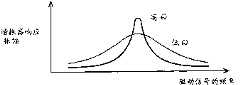
图5A示意性地表示在形成图4中所示传感器元件的一部分的谐振电路中感应的信号的相位如何随着驱动信号的频率变化;Figure 5A schematically represents how the phase of a signal induced in a resonant circuit forming part of the sensor element shown in Figure 4 varies with the frequency of the drive signal;
图5B示意性地表示在形成图4中所示传感器元件的一部分的谐振电路中感应的信号的振幅如何随着驱动信号的频率变化;Figure 5B schematically represents how the amplitude of the signal induced in the resonant circuit forming part of the sensor element shown in Figure 4 varies with the frequency of the drive signal;
图6A是表示施加于图3B中所示余弦线圈的信号的时序图;FIG. 6A is a timing diagram representing signals applied to the cosine coil shown in FIG. 3B;
图6B是表示施加于图3A中所示正弦线圈的第一信号的时序图;FIG. 6B is a timing diagram representing a first signal applied to the sinusoidal coil shown in FIG. 3A;
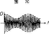
图6C是表示施加于图3A中所示正弦线圈的第二信号的时序图;FIG. 6C is a timing diagram representing a second signal applied to the sinusoidal coil shown in FIG. 3A;
图7A-7C是表示当对于传感器元件的三个不同位置当将图6A中所示信号施加于余弦线圈和将图6B中所示信号施加于正弦线圈时,在图3C中所示读出线圈中感应的信号的时序图;Figures 7A-7C are graphs showing the readout coil shown in Figure 3C when the signal shown in Figure 6A is applied to the cosine coil and the signal shown in Figure 6B is applied to the sine coil for three different positions of the sensor element. The timing diagram of the signal induced in
图8A-8C是表示当对于传感器元件的三个不同位置当将图6A中所示信号施加于余弦线圈和将图6C中所示信号施加于正弦线圈时,在图3C中所示读出线圈中感应的信号的时序图;Figures 8A-8C are graphs showing the readout coil shown in Figure 3C when the signal shown in Figure 6A is applied to the cosine coil and the signal shown in Figure 6C is applied to the sine coil for three different positions of the sensor element. The timing diagram of the signal induced in
图9是更详细地表示图1中所示位置传感器的处理电路的方框图;Fig. 9 is a block diagram showing in more detail the processing circuitry of the position sensor shown in Fig. 1;
图10更详细地表示图9中所示处理电路的模拟信号处理元件;Figure 10 shows in more detail the analog signal processing elements of the processing circuit shown in Figure 9;
图11A-11D是表示在图9中所示处理电路内在各个位置的信号的时序图;11A-11D are timing diagrams representing signals at various locations within the processing circuit shown in FIG. 9;
图12是表示在图9中所示处理电路的微处理器形成部分接收的脉冲的时序图;Figure 12 is a timing diagram representing pulses received in the microprocessor forming part of the processing circuit shown in Figure 9;
图13是表示进行计算图1中所示位置传感器的传感器元件的位置的操作的流程图;13 is a flow chart showing an operation performed to calculate the position of the sensor element of the position sensor shown in FIG. 1;
图14是更详细地表示进行计算图1中所示位置传感器的传感器元件的位置所使用的正向角度的操作的流程图;和FIG. 14 is a flowchart showing in more detail the operations performed to calculate the forward angle used for the position of the sensor element of the position sensor shown in FIG. 1; and
图15是更详细地表示进行计算图1中所示位置传感器的传感器元件的位置所使用的反向角度的操作的流程图。FIG. 15 is a flowchart showing in more detail the operation performed to calculate the reverse angle used for the position of the sensor element of the position sensor shown in FIG. 1 .
图1示意性地表示用于检测传感器元件1的位置的位置传感器,该传感器元件1可滑动地安装在支架3上,从而可以沿着测量方向(图1中的X方向)线性运动。印刷电路板(PCB)5沿着与支架3相邻的测量方向延伸并且具有印刷在其上的导电迹线,该导电迹线形成正弦线圈7、余弦线圈9和读出线圈11,所述每个线圈都连接到控制单元13。显示器15也连接到控制单元13,用于显示表示传感器元件1沿着支架3的位置的数字。Fig. 1 schematically shows a position sensor for detecting the position of a
如图1所示,在外形上,PCB 5一般是矩形的,其长轴与测量方向对准,短轴垂直于测量方向。正弦线圈7、余弦线圈9和读出线圈11经PCB5的长边连接到控制单元,这对应X等于零的位置值,该位置值沿着PCB 5的长度从对应X等于零的长边而增加。As shown in Fig. 1, in appearance, the
现在参照图2介绍图1中所示位置传感器的操作的概要。控制单元13包括在各个不同的输出端产生同相信号I(t)和正交信号Q(t)的正交信号发生器21。同相信号I(t)是使用在调制频率f1振荡的第一调制信号,通过具有载频f0的振荡载波信号的调幅产生的,在本实施例中,载频f0为2MHz,调制频率f1为3.9KHz。因此同相信号I(t)为如下形式:An outline of the operation of the position sensor shown in FIG. 1 will now be described with reference to FIG. 2 . The
I(t)=Asin2πf1tcos2πf0t (1)I(t)=Asin2πf1 tcos2πf0 t (1)
同样,正交信号Q(t)是使用在调制频率f1振荡的第二调制信号,通过具有载频f0的振荡载波信号的调幅产生的,其中第二调制信号与第一调制信号的相位相差π/2弧度(90度)。因此正交信号Q(t)为如下形式:Likewise, the quadrature signal Q(t) is generated by amplitude modulation of an oscillating carrier signal having a carrier frequencyf0 using a second modulating signal oscillating at modulating frequencyf , where the second modulating signal is out of phase with the first modulating signal The difference is π/2 radians (90 degrees). Therefore, the quadrature signal Q(t) has the following form:
Q(t)=Acos2πf1tcos2πf0t (2)Q(t)=Acos2πf1 tcos2πf0 t (2)
同相信号I(t)被施加给正弦线圈7,正交信号Q(t)被施加给余弦线圈9。The in-phase signal I(t) is applied to the
正弦线圈7以这种模式形成:使得电流流过正弦线圈7,从而产生第一磁场B1,垂直于PCB5分解的第一磁场B1的场强分量根据以下函数沿着测量方向正弦地变化:The
B1=Bsin(2πx/L) (3)B1 =Bsin(2πx/L) (3)
其中L是在X方向的正弦线圈的周期。where L is the period of the sinusoidal coil in the X direction.
同样,余弦线圈9以这种模式形成:使得电流流过余弦线圈9,从而产生第二磁场B2,垂直于PCB5分解的第二磁场B2的场强分量也沿着测量方向正弦地变化,但是具有相对于第一磁场B1的相位的π/2弧度(90度)的相位差,如下给出:Likewise, the
B2=Bcos(2πx/L) (4)B2 =Bcos(2πx/L) (4)
通过这种方式,在沿着测量方向的任何位置产生的总磁场BT将由来自第一磁场B1的第一分量和来自第二磁场B2的第二分量形成,垂直于PCB5分解的第一和第二分量的大小沿着测量方向变化。In this way, the total magnetic fieldBT generated at any position along the measuring direction will be formed by the first component from the first magnetic fieldB1 and the second component from the second magnetic fieldB2 , perpendicular to the first and the magnitude of the second component varies along the measurement direction.
通过分别给正弦线圈7和余弦线圈9施加同相信号I(t)和正交信号Q(t),产生的垂直于PCB5分解的总磁场分量BT根据在调制频率f1变化的振幅包络函数在载频f0振荡,其中振幅包络函数的相位沿着测量方向而变化。因此:By applying the in-phase signal I(t) and the quadrature signal Q(t) to the
BT∝cos2πf0t.cos(2πf1t-2πx/L) (5)BT∝cos2πf0 t.cos(2πf1 t-2πx/L) (5)
实际上,振幅包络函数的相位沿着测量方向旋转。在本实施例中,传感器元件1包括具有基本上等于载频f0的谐振频率的谐振电路。因此总磁场分量BT在该谐振电路中感应电信号,该电信号在载频f0振荡并具有在调制频率f1调制的振幅,其中其相位沿着测量方向由传感器元件1的位置决定。在谐振电路中感应的电信号又产生磁场,该磁场在读出线圈11中感应读出电信号S(t),该读出电信号S(t)在载频f0处振荡。读出信号S(t)的振幅也在调制频率f1被调制,并且相位取决于传感器元件1沿着测量方向的位置。读出信号S(t)被输入到解调读出信号S(t)的相位检测器23,从而除去在载频f0的分量,并检测其余振幅包络函数相对于激励波形的相位。然后相位检测器23向位置计算器25输出表示被检测相位的相位信号P(t),该位置计算器25将被检测相位转换成相应的位置值并向显示器15输出驱动信号,从而显示相应位置值。In effect, the phase of the amplitude envelope function rotates along the measurement direction. In the present embodiment, the
通过使用大于调制频率f1的载频f0,在远离低频噪声源如在50/60Hz的电力干线的频率下进行感应耦合,同时仍然可以在很好地适于数字处理的相对低频进行信号处理。此外,增加载频f0便于使传感器元件1变小,这在很多应用中都是显著的优点。提高载频f0还产生更高的信号强度。By using a carrier frequency f0 greater than the modulation frequency f1 , inductive coupling is performed at frequencies away from low frequency noise sources such as power mains at 50/60 Hz while still allowing signal processing at relatively low frequencies well suited for digital processing . Furthermore, increasing the carrier frequency f0 facilitates making the
下面更详细地介绍图1中所示位置传感器的分开的部件。The separate components of the position sensor shown in FIG. 1 are described in more detail below.
如图3A所示,正弦线圈7是由一般围绕远离在测量方向上沿着PCB5的一半路程的交叉点的PCB5的周边延伸的导电迹线形成的,其中PCB5的每个短边上的导电迹线与PCB5的相应相对短边交叉。通过这种方式,有效地形成了第一电流回路21a和第二电流回路21b。当信号被施加给正弦线圈7时,电流围绕第一电流回路21a和第二电流回路21b在相反方向流动,因此围绕第一电流回路21a流动的电流产生磁场,该磁场的极性与由围绕第二电流回路21b流动的电流产生的磁场的极性相反。这导致垂直于PCB5分解的由上述等式3给出的第一磁场B1的分量的场强呈正弦变化。As shown in Figure 3A, the
特别是,正弦线圈7的布图使得由流过正弦线圈7的电流产生的垂直于PCB5分解的第一磁场B1的分量的场强沿着测量方向从X等于0的点的大约零值变化到X为L/4位置(如图3A所示的位置A)的最大值,然后在X等于L/2的位置(如图3A所示的位置C)返回到零,然后在X等于3L/4位置达到最大值(具有与位置A的最大值相反的极性),再然后在X等于L的位置返回到零。因此,正弦线圈7产生垂直于PCB5的磁场分量,该磁场分量根据正弦函数的一个周期变化。In particular, the layout of the
如图3B所示,余弦线圈9由一般围绕远离两个交叉点的PCB5的周边延伸的导电迹线形成,其中所述两个交叉点分别位于在测量方向沿着PCB5的四分之一和四分之三途中的位置上。通过这种方式,形成三个回路23a、23b和23c,其中外部回路23a和23c是内部回路23b的尺寸的一半。当信号被施加给余弦线圈9时,电流在一个方向围绕外部回路23a和23c流动,并在相反方向围绕内部回路23b流动。通过这种方式,由围绕内部回路23b流动的电流产生的磁场的极性与由围绕外部回路23a和23c流动的电流产生的磁场的极性相反。这导致由上述等式4给出的垂直于PCB5分解的第二磁场B2的分量的场强按正弦变化。As shown in FIG. 3B , the
特别是,余弦线圈9的布图使得由流过余弦线圈9的电流产生的垂直于PCB5分解的第二磁场B2的分量的场强沿着测量方向从X等于0位置的最大值变化到X等于L/4位置(如图3B所示的位置A)的零值,然后在X等于L/2的位置(如图3B所示的位置C)返回到最大值(具有与X等于0的位置的最大值相反的极性),然后在X等于3L/4位置达到零,再然后在X等于L的位置为最大值(具有与X等于0的位置的最大值相同的极性)。因此,正弦线圈7产生垂直于PCB5的磁场分量,该磁场分量根据上述等式4给出的余弦函数的一个周期变化。In particular, the layout of the
如图3C所示,读出线圈11由一般围绕PCB5的周边延伸并形成单回路的导电迹线形成。As shown in Figure 3C, the
正弦线圈7的布图使得由围绕第一电流回路21a流动的电流在读出线圈11中感应的电流基本上被由围绕第二电流回路21b流动的电流在读出线圈11中感应的电流抵消。同样,对于余弦线圈9,由外部回路23a和23c在读出线圈11中感应的电流被由内部回路21b在读出线圈11中感应的电流抵消。使用这种平衡线圈具有的进一步的优点是:来自正弦线圈7和余弦线圈9的电磁发射随着以比单平面线圈快的速度运行的距离而减小。这允许使用更大的驱动信号,同时仍然满足电磁发射的调整需求。这是特别重要的,因为电磁发射的调整需求变得越来越严格了。The layout of the
图4更详细地示出了传感器元件1。如图所示,在本实施例中,传感器元件1包括线圈31,该线圈31的端部经电容器33连接在一起。由于线圈31具有相关的电感,因此线圈31和电容器33一起形成谐振电路。在本实施例中,谐振电路具有2MHz的标称谐振频率fres(这等于载频f0),尽管实际谐振频率将根据诸如温度和湿度之类的环境因素而变化。Figure 4 shows the
如上所述,当振荡驱动信号被施加于正弦线圈7和余弦线圈9中的一个或两个上时,在传感器元件1的谐振电路中感应相同频率的振荡信号。然而,在驱动信号和感应信号之间产生相位滞后,相位滞后的量取决于驱动信号的频率和谐振电路的谐振频率之间的关系。如图5A所示,相位滞后在谐振电路的谐振频率附近变化最快,在谐振频率的相位滞后为π/2弧度(90度)。谐振电路的品质因数越高,相位在谐振频率附近的变化越快。然而,如图5B所示,谐振电路的品质因数越低,在谐振电路中感应的电信号的振幅越小。因此当选择谐振电路的品质因数值时,必须对信号强度和相位随频率变化的速度之间达成折衷方案。As described above, when an oscillating drive signal is applied to one or both of the
下面参照图6A-6C更详细地介绍由正交信号发生器21产生并作为驱动信号施加给正弦线圈7和余弦线圈9的正交信号。The quadrature signal generated by the
如图6A所示,通过使用第一调制信号调制载波信号,正交信号发生器21产生正交信号Q(t)。如图所示,在本实施例中,第一调制信号不给载波信号施加“全面”调制。换言之,由图6A中所示的虚线表示的振幅包络函数没有达到零振幅。因此实际正交信号Q(t)给出如下:As shown in FIG. 6A, the
Q(t)=Ccos2πf0t+Bcos2πf1tcos2πf0t (6)Q(t)=Ccos2πf0 t+Bcos2πf1 tcos2πf0 t (6)
如图6B所示,通过使用第二调制信号调制载波信号的振幅,正交信号发生器21产生同相信号I(t),其中第二调制信号的相位比第一调制信号的相位滞后π/2弧度(即90度)。而且,在本实施例中,第二调制信号不给载波信号施加全面调制。因此实际同相信号I(t)给出如下:As shown in FIG. 6B, the
I(t)=Ccos2πf0t+Bsin2πf1tcos2πf0t (7)I(t)=Ccos2πf0 t+Bsin2πf1 tcos2πf0 t (7)
同相信号I(t)和正交信号Q(t)各包括三个频率分量,一个在f0,一个在(f0+f1),一个在(f0-f1)。从图5A中看出,这三个分量将在传感器元件1的谐振电路中以各自不同的相位滞后分别感应一个电信号。这将导致读出信号S(t)的相位偏移,考虑到读出信号S(t)的相位被用于确定传感器元件1的位置,为了获得准确的位置测量而必须校正这种相位偏移。在本实施例中,如后面更详细说明的,这种校正是通过用“反相”信号I(t)代替同相信号I(t)而进行第二相位测量来实现的。The in-phase signal I(t) and the quadrature signal Q(t) each include three frequency components, one at f0 , one at (f0 +f1 ), and one at (f0 −f1 ). It can be seen from FIG. 5A that these three components will each induce an electrical signal with a respective different phase lag in the resonant circuit of the
如图6C所示,通过使用也处于调制频率f1的第三调制信号调制载波信号(具有载频f0),正交信号发生器21产生反相信号I(t),其中第三调制信号的相位比第一调制信号的相位超前π/2弧度(即90度)。而且,在本实施例中,第三调制信号不给载波信号施加全面调制。因此反相信号I(t)给出如下:As shown in FIG. 6C , by modulating the carrier signal (with carrier frequency f0 ) with a third modulation signal also at modulation frequency f1 ,
I(t)=Ccos2πf0t-Bsin2πf1tcos2πf0t (8)I(t)=Ccos2πf0 t-Bsin2πf1 tcos2πf0 t (8)
现在参照图7A-7C介绍当同相信号I(t)和正交信号Q(t)分别施加于正弦线圈7和余弦线圈9时在读出线圈11中感应的读出信号S(t)。在图7A-7C中,假设谐振电路没有引入相位偏移,因此,相位偏移完全是由于传感器元件1的位置造成的。The readout signal S(t) induced in the
图7A示出了当传感器元件1与点A(其中X等于L/4)相邻定位时的读出信号S(t),其中A点与图3A-3C中相同。在点A,由余弦线圈9产生的磁场的场强大约为零,因此假设没有由于谐振电路产生的相位偏移,读出信号S(t)与同相信号I(t)匹配。因此,读出信号S(t)相对于正交信号Q(t)具有π/2弧度(90度)的相位滞后。Fig. 7A shows the readout signal S(t) when
图7B示出了当传感器元件1与点B(其中X等于3L/8)相邻定位时的读出信号S(t),其中在点B,由正弦线圈7和余弦线圈9产生的磁场的场强大约相等,因此,假设没有由于谐振电路产生的相位偏移,读出信号S(t)相对于正交信号Q(t)具有π/4弧度(45度)的相位滞后。FIG. 7B shows the readout signal S(t) when the
图7C示出了当传感器元件1与点C(其中X等于L/2)相邻定位时的读出信号S(t),其中在点C,由正弦线圈7产生的磁场的场强大约为零,因此,假设没有由于谐振电路产生的相位偏移,读出信号S(t)与正交信号Q(t)匹配。因此,读出信号S(t)与正交信号Q(t)同相。FIG. 7C shows the readout signal S(t) when the
从上面的等式5看出,当同相信号I(t)和正交信号Q(t)分别施加于正弦线圈7和余弦线圈9时,读出信号S(t)的相位随着位置值增加而减小。It can be seen from
现在参照图8A-8C介绍当反相信号I(t)和正交信号Q(t)被分别施加给正弦线圈7和余弦线圈9时在读出线圈11中感应的读出信号S(t)。而且,假设谐振电路没有引入相位偏移,因此相位偏移完全由传感器元件1的位置产生。The readout signal S(t) induced in the
图8A示出了当传感器元件1与点A相邻定位时的读出信号S(t),其中在点A,由余弦线圈9产生的磁场的场强大约为零,因此假设谐振电路没有引入相位偏移,读出信号S(t)与反相信号I(t)匹配。因此,读出信号S(t)的相位比正交信号Q(t)的相位超前π/2弧度(90度)。Fig. 8A shows the readout signal S(t) when the
图8B示出了当传感器元件1与点B相邻定位时的读出信号S(t),其中在点B,由正弦线圈7和余弦线圈9产生的磁场的场强大约相等,因此,假设谐振电路没有引入的相位偏移,读出信号S(t)的相位比正交信号Q(t)的相位超前π/4弧度(45度)。8B shows the readout signal S(t) when the
图8C示出了当传感器元件1与点C相邻定位时的读出信号S(t),其中在点C,由正弦线圈7产生的磁场的场强大约为零,因此,假设谐振电路没有引入的相位偏移,读出信号S(t)与正交信号Q(t)同相。FIG. 8C shows the readout signal S(t) when the
如图8A-8C所示,当反相信号I(t)和正交信号Q(t)被分别施加给正弦线圈7和余弦线圈9时,读出信号S(t)的相位随着位置值而线性增加。As shown in Figures 8A-8C, when the inversion signal I(t) and the quadrature signal Q(t) are applied to the
如上所述,假设谐振电路没有引入相位偏移,对于测量方向的每个位置X,当施加同相信号I(t)和正交信号Q(t)时,引入与位置相关的相位偏移φ(x),并且当施加反相信号I(t)和正交信号Q(t)时,引入与位置相关的相位偏移-φ(x)。实际上,谐振电路的确引入相位偏移φRC,但是不管给正弦线圈7施加同相信号I(t)还是反相信号I(t),相位偏移φRC一般都是相同的。因此,本实施例中,从施加同相信号I(t)时测量的相位偏移减去施加反相信号I(t)时测量的相位偏移,结果是由谐振电路引入的相位偏移φRC被取消,从而提供等于与位置相关的相位偏移φ(x)的两倍的合成相位。As mentioned above, assuming that the resonant circuit does not introduce a phase shift, for each position X in the measurement direction, when the in-phase signal I(t) and the quadrature signal Q(t) are applied, a position-dependent phase shift φ is introduced (x), and when the inverted signal I(t) and the quadrature signal Q(t) are applied, a position-dependent phase offset -φ(x) is introduced. Actually, the resonant circuit does introduce a phase shift φRC , but the phase shift φRC is generally the same no matter whether the in-phase signal I(t) or the anti-phase signal I(t) is applied to the
现在参照图9介绍用于产生同相信号I(t)、正交信号Q(t)和反相信号I(t)以及处理读出信号S(t)以确定位置值的处理电路。如图9所示,该处理电路由微处理器41、数字部件61、模拟驱动电路81和模拟信号处理部件91构成。Referring now to FIG. 9, the processing circuitry for generating the in-phase signal I(t), quadrature signal Q(t) and inverted signal I(t) and processing the readout signal S(t) to determine a position value is described. As shown in FIG. 9 , the processing circuit is composed of a
微处理器41包括在两倍于载频f0的频率(即在4MHz)产生方波信号的第一方波振荡器43。这个方波信号从微处理器41输出到正交分配器单元63,该正交分配器单元63将该方波信号分成两份,并形成在载频处的同相数字载波信号+I、在载频处的反相数字载波信号-I、和也在载频处的正交数字载波信号+Q。如下所述,正交数字载波信号+Q被调制以便形成施加给正弦线圈7和余弦线圈9的驱动信号,而同相和反相载波信号±I用于进行同步检测,以便解调读出信号S(t)。The
微处理器41还包括第二方波振荡器45,该第二方波振荡器45输出在调制频率f1的调制同步信号MOD_SYNC,以便提供参考定时。该调制同步信号MOD_SYNC被输入到脉宽调制(PWM)型图形发生器47,该发生器47产生2MHz的数字数据流,表示在调制频率f1即3.9KHz的调制信号。特别是,PWM型图形发生器47产生相位彼此正交的两个调制信号,即余弦信号COS和相加正弦或相减正弦信号±SIN,这取决于要产生的是同相信号I(t)还是反相信号I(t)。The
余弦信号COS由微处理器41输出并施加于第一数字混合器65,在本实施例中,该第一数字混合器65是NOR门,它将余弦信号和正交数字载波信号+Q混合,从而产生表示正交信号Q(t)的数字。正弦信号±SIN由微处理器输出并施加于第二数字混合器67,在本实例中,该数字混合器67是NOR门,它与正交数字载波信号+Q一起产生表示同相信号I(t)或反相信号I(t)的数字。从第一和第二数字混合器65、67输出的数字信号分别输入给第一和第二线圈驱动器电路83、85,然后由线圈83、85输出的放大信号分别被施加给余弦线圈9和正弦线圈7。The cosine signal COS is output by the
被施加给正弦线圈7和余弦线圈9的驱动信号的数字产生引入高频谐波噪声。然而,线圈驱动器65、67除去了这些高频谐波噪声中的一部分,如余弦和正弦线圈7、9的频率响应特性那样。此外,传感器元件1内的谐振电路将不响应远远高于谐振频率的信号,因此谐振电路也将滤除一部分不希望的高频谐波噪声。The digital generation of the drive signals applied to the
如上所述,被施加给正弦线圈7和余弦线圈9的信号感应在传感器元件1的谐振电路中的电信号,而该电信号又在读出线圈11中感应读出信号S(t)。该读出信号S(t)通过模拟信号处理部件91。特别是,读出信号S(t)最初通过高通滤波放大器93,该高通滤波放大器93即放大接收的信号又除去低频噪声(例如来自于50Hz主电力输送装置)和任何DC偏置。然后从高通滤波器93输出的放大信号输入到交叉模拟开关95,该交叉模拟开关使用由正交驱动器21产生的同相和反相方波载波信号±I在2MHz的载频进行同步检测。相位与正交数字载波信号+Q相差90度的同相和反相数字载波信号用于产生施加给正弦线圈7和余弦线圈9的驱动信号,该驱动信号用于同步检测,如上所述,因为传感器元件1的谐振电路给载波信号引入了大致90度的相移。As mentioned above, the signal applied to the
从交叉模拟开关95输出的信号基本上对应输入到交叉模拟开关95的信号的全整流形式(即具有在零电压线上重叠的信号中的负电压谷值,从而形成位于原始电压峰值之间的电压峰值)。然后这个整流信号通过低通滤波放大器97,该低通滤波放大器97主要产生具有DC分量和在调制频率f1的分量的时间-平均或平滑信号。DC分量作为同步检测处理执行的整流的结果出现的。The signal output from the
然后从低通滤波放大器97输出的信号输入到以调制频率f1为中心的带通滤波放大器99,除去DC分量。从带通滤波放大器99输出的信号被输入到比较器101,该比较器101将输入信号转换成方波信号,该方波信号的定时与调制同步信号MOD_SYNC的定时相比较,从而确定传感器元件1的位置。The signal output from the low-
图10更详细地示出了模拟信号处理部件91。如图所示,读出线圈11的一端连接在两个电阻器R1和R2之间,而电阻器R1和R2串联连接在电源电压和“真实”地之间,从而设定有效地电压电平VAG。特别是,在本实施例中,电源电压为5V,电阻器R1的电阻等于电阻器R2的电阻,从而提供2.5V的有效地电压电平。Figure 10 shows the analog
图11A示出了调制同步信号MOD_SYNC,图11B示出了在读出线圈11中感应的读出信号S(t)。如图所示,可以看出,读出信号S(t)的振幅包络函数与调制同步信号MOD_SYNC不是同相的。图11C示出了由低通滤波放大器97输出的信号111,该信号基本上对应振幅包络函数。图11D表示由带通滤波放大器99输出的信号113和由比较器101输出的方波115。FIG. 11A shows the modulation synchronization signal MOD_SYNC, and FIG. 11B shows the readout signal S(t) induced in the
在本实施例中,比较器101是反相比较器,当从带通滤波放大器99输出的信号113低于参考电压电平Vref时其输出为高(即5V),当从带通滤波放大器输出的信号113高于参考电压电平Vref时,其输出为低(即0V)。如从图10看出的,参考电压电平Vref不是有效地电压电平VAG,而是低于有效地电压电平VAG的电压,该电压是从连接在有效地电压电平VAG和真实地之间的两个电阻器R3和R4之间提取的。这防止了在除了少量噪声之外从带通滤波放大器99没有输出时比较器101产生寄生信号。然而,这也意味着由比较器101输出的信号的前缘和后缘与由带通滤波放大器99输出的信号113和有效地电压电平VAG交叉的点不一致。为了避免这引入相位误差,由比较器101输出的信号115的定时由后缘和前缘之间的中点的定时决定。特别是,如图11D所示,如果后缘处于时间t1,前缘处于时间t2,则测量时间对应(t1+t2)/2。In this embodiment, the
回到参见图9,由比较器101输出的方波信号(它实际上为数字信号)与由正交分配器63输出的正交数字载波信号+Q一起施加于数字门69,在本实施例中该数字门69为NOR门。因此当来自比较器101的输出为低(即0V)时,数字门69在载频f0输出一系列脉冲,当比较器101的输出为高(即5V)时,数字门69不输出信号。图12示出了在MOD_SYNC信号的一个周期内,来自数字门69的输出的例子,后面将上述一个周期称为一帧。Referring back to Fig. 9, the square wave signal (actually a digital signal) output by the
如图9所示,从数字门69输出的脉冲被输入到形成微处理器41的一部分的计数器49。由第二方波振荡器45输出的MOD_SYNC信号被输入到频率倍增器51,在本实施例中,该频率倍增器51将MOD_SYNC信号的频率增加16倍,并向计数器49输出倍增后的信号。倍增信号的每个周期τN将在后面称为窗口,从而一帧对应16个窗口,称为窗口1到窗口16。在本实施例中,调制频率设定为2MHz/29=3.9KHz。这意味着每个帧对应输入给数字门25的载波信号+Q的512个周期,每个窗口对应载波信号+Q的32个周期(512/16)。As shown in FIG. 9 , the pulse output from the
在一帧内的每个窗口之后,计数器49的计数值被处理单元53记录和储存,然后复位到零。这样,对于每个帧,处理单元接收16个计数值,处理单元53由该计数值确定传感器元件1的位置和向显示控制器55输出表示确定位置的信号,该显示控制器55向显示器15输出驱动信号,从而表示确定位置。After each window within a frame, the count value of the
现在将参照图13-15更详细地介绍由处理单元53进行的确定传感器元件1的位置的处理。The process of determining the position of the
如图13所示,处理单元53首先给PWM型图形发生器47发送控制信号,该PWM型图形发生器47通过输出余弦信号COS和相加正弦信号+SIN而响应,以便在步骤S1中给正弦线圈7和余弦线圈9分别施加同相信号I(t)和正交信号Q(t)。然后,在步骤S3中,处理单元53使用十六个计数值测量读出信号S(t)和MOD_SYNC信号之间的相位角,其中所述计数值对应在施加同相信号I(t)和正交信号Q(t)时获得的那一帧,所述相位角在后面将称为正向角。As shown in FIG. 13, the
图14示出了进行测量正向角的主要步骤。首先,在步骤S21中,处理单元53识别对应由带通滤波放大器99输出的信号113与参考电压Vref在正方向相交时的脉冲。特别是,通过识别各个计数值为0、介于0和32之间的数字n1和32的三个连续窗口来识别这个“正零交叉”脉冲。然后通过(k+1)乘以32然后减去窗口k+1的计数值n1,计算正零交叉脉冲的脉冲数P1。因此,对于图12中所示的典型帧,k等于3,正零交叉脉冲的脉冲数P1为124(即(4×32)-4)。Figure 14 shows the main steps in performing the measurement of the forward angle. First, in step S21 , the
接着,在步骤S23中,处理单元53识别对应由带通滤波放大器99输出的信号113与参考电压Vref在负方向相交时的脉冲。通过识别各个计数值为32、介于0和32之间的数字n2和0的三个连续窗口(以下将称为窗口1、1+1、1+2)来识别这个“负零交叉脉冲”。然后通过1乘以32并加上窗口1+1的计数值n2,计算负零交叉脉冲的脉冲数P2。因此,对于图12中所示的典型帧,1等于12,负零交叉脉冲的脉冲数为386(即(12×32)+2)。Next, in step S23 , the
然后,在步骤S25中,处理单元53确定脉冲数P1是否大于脉冲数P2,如果通过一系列脉冲的中途发生一帧的开始,则脉冲数P1将大于P2。如果确定脉冲数P1大于脉冲数P2,则在步骤S27中,处理单元53将512(即对应一帧的脉冲数)加到脉冲数P2的值上。然后,通过平均脉冲数P1和P2(即(P1+P2)/2)以获得对应一列脉冲的中点的脉冲数,然后将获得的脉冲数乘以360/512,从而处理单元53设定对应从一帧开始到一列脉冲的中点的定时的正向角。Then, in step S25, the
然后,在步骤S31中,处理单元53检测是否正向角大于360度,如果通过一列脉冲的中途发生一帧的开始,则可能发生正向角大于360度。如果正向角大于360度,则在步骤S33中处理单元53从正向角中减去360。Then, in step S31, the
回到图13,测量正向角之后,处理单元53向PWM型图形发生器47发送控制信号,该PWM型图形发生器47通过输出余弦信号COS和相减正弦信号-SIN而响应,以便在步骤S5中分别向正弦线圈7和余弦线圈9施加反相信号I(t)和正交信号Q(t)。然后,在步骤S7中,处理单元53使用十六个计数值测量读出信号S(t)和MOD_SYNC信号之间的反向相位角,该反向相位角在后面将称为反向角,其中所述十六个计数值对应在施加反相信号I(t)和正交信号Q(t)时获得的帧。Returning to Fig. 13, after measuring the forward angle, the
图15示出了进行测量反向角的主要步骤。首先,利用与上述正向角计算相同的方式,处理单元在步骤S41中确定正零交叉脉冲的脉冲数P1和在步骤S43中确定负零交叉脉冲的脉冲数P2。然后,在步骤S45中,处理单元53确定是否脉冲数P1大于脉冲数P2,如果存在这种情况,则在步骤S47中处理单元将512加到脉冲数P2的值上。Figure 15 shows the main steps for performing the measurement of the reverse angle. First, the processing unit determines the pulse number P1 of positive zero-crossing pulses in step S41 and the pulse number P2 of negative zero-crossing pulses in step S43 in the same way as the above-mentioned positive angle calculation. Then, in step S45, the
然后,在步骤S49中,通过对脉冲数P1和P2求平均值获得对应一列脉冲的中点的脉冲数,然后将获得的脉冲数乘以360/512并从360中减去相乘的结果,由此处理单元53设定对应从一帧结束到一列脉冲的中点的定时的反向角。然后,在步骤S51中,处理单元53检测是否反向角小于0度,如果脉冲序列跨越两个帧则将发生这种情况,并且如果在种情况下,在步骤S53中,将360加到反向角上。Then, in step S49, the pulse number corresponding to the midpoint of a train of pulses is obtained by averaging the pulse numbersP1 andP2 , and then the obtained pulse number is multiplied by 360/512 and subtracted from 360 by As a result, the
回到图13,然后,在步骤S9中,处理单元53对正向角和反向角求平均值,如上所述,除去由传感器元件1内的谐振电路引入的固定相移φRC,从而提供表示传感器元件1的位置的平均角。然后,在步骤S11中,处理单元53通过将比例系数乘以该平均角而将该平均角转换成位置值。然后在显示器15上显示该位置值。Returning to Figure 13, then, in step S9, the
改进和其它实施例Improvements and other embodiments
由谐振电路引入的相移φRC的量取决于调制频率f1,因为调制频率越低,由正弦线圈7和余弦线圈9产生的磁场的频率分量在频率上越靠近。例如,如果调制频率f1等于谐振频率除以品质因数的十倍,则相移φRC大约为10度,然而,如果调制频率f1等于谐振频率处以品质因数的100倍,则相移φRC大于为1度。这暗示着调制频率f1应该尽可能地低。然而,减小调制频率的缺点是帧的持续时间增加了,因此测量需要更长的时间,并且更新速度减小了。The amount of phase shift φRC introduced by the resonant circuit depends on the modulation frequency f1 , since the lower the modulation frequency, the closer the frequency components of the magnetic field generated by the
如上所述,通过有效地采用利用施加于正弦线圈7的信号的相位在测量值之间相反位置的两个测量值除去由传感器元件1中的谐振电路引入的相移φRC。应该理解,在替换实施例中,只须间歇地进行反向测量,从而确定相移φRC的值,这具有增加测量值更新速度的优点。或者,可以从单相位测量值中减去由工厂刻度确定的相移φRC的预定值。然而,这不是优选的,因为对于环境因素来说这是不允许的,环境因素将影响谐振电路的谐振频率fres和品质因数,因此改变相移φRC。As mentioned above, the phase shift φRC introduced by the resonant circuit in the
应该理解,如果从正向角减去而不是加上反向角,则位置-相关相移φ(x)将被除去,留下等于两倍于相移φRC的值。因为相移随环境因素而改变,相移φRC的测量值可表示环境因素。因此,所述感应传感器也可用作例如温度传感器(在恒定湿度环境下)或湿度传感器(在恒定温度环境下)。通常,这将包括在感应传感器的控制电路中储存测量相移φRC和环境因素的相应值之间的工厂刻度。It will be appreciated that if the forward angle is subtracted from rather than added to, the position-dependent phase shift φ(x) will be removed leaving a value equal to twice the phase shift φRC . Because the phase shift varies with environmental factors, the measured value of the phase shift φRC can be indicative of environmental factors. Thus, the inductive sensor can also be used as, for example, a temperature sensor (in a constant humidity environment) or a humidity sensor (in a constant temperature environment). Typically this will involve storing a factory scale between the measured phase shift φRC and the corresponding value of the environmental factor in the control circuit of the inductive sensor.
在本发明的实施例中,所述感应传感器用于远程检测容器内的液体的温度。特别是,传感器元件1放在容器内,以便它浸在液体中,同时正弦线圈7、余弦线圈9和读出线圈11与容器的外部相邻地定位。如上述那样计算正向角和反向角,然后相加以提供表示相移φRC的值。然后处理单元53访问储存测量相移φRC和温度之间的工厂刻度的查询表,从而获得温度值。应该理解,由于传感器元件浸在液体中,因此在恒定湿度环境下是有效的。还应该理解,使用感应传感器的优点是不需要为了从传感器元件获得电信号而在容器中穿孔。In an embodiment of the invention, the inductive sensor is used to remotely detect the temperature of the liquid in the container. In particular, the
根据本发明的感应传感器的另一应用是检测用于优化干燥周期的衣服干燥器的排放湿度。Another application of the inductive sensor according to the invention is the detection of the discharge humidity of a clothes dryer for optimizing the drying cycle.
应该理解,环境因素的检测可以代替或附加地检测两个相对可移动部件的相对位置来进行。It should be understood that detection of environmental factors may be performed instead of or in addition to detection of the relative position of two relatively movable parts.
在上述实施例中,正弦线圈7和余弦线圈9被设置成使得它们对垂直于PCB 5的总磁场分量的补偿根据沿着测量方向的位置而改变。特别是,正弦和余弦线圈具有交替扭绞回路结构。然而,对于本领域技术人员来说,很显然各种不同激励线圈几何结构都可以用于形成传输天线,实现使第一和第二传输信号的相对比例呈现在最终检测的组合信号中的目的,从而在测量方向确定传感器元件的位置。In the above embodiment, the
在上述实施例中,激励线圈由印刷电路板上的导电迹线形成,它们还可以设置在不同平面衬底上,或者,如果足够硬的话,甚至可以是不固定的。此外,激励线圈为平面的不是主要的,因为,例如,随着传感器元件沿着圆筒形线圈的圆筒轴移动,也可以使用圆筒形线圈。In the embodiments described above, the excitation coils are formed by conductive traces on a printed circuit board, they may also be provided on a different planar substrate or, if sufficiently rigid, may even be unfixed. Furthermore, it is not essential that the excitation coil is planar, since, for example, cylindrical coils can also be used as the sensor element is moved along the cylindrical axis of the cylindrical coil.
如果感应传感器只用于测量环境因素,如温度或湿度,则只有一个传输天线可使用,因为不要求磁场的相位随位置变化。If the inductive sensor is only used to measure environmental factors, such as temperature or humidity, then only one transmitting antenna can be used because there is no requirement that the phase of the magnetic field vary with position.
在上述实施例中,一对正交调制信号被施加给载波信号,从而产生分别施加于正弦线圈7和余弦线圈9的第一和第二激励信号。然而,这不是主要的,因为只要求承载激励信号的分量的信息在某些方面不同,以便来自第一和第二激励信号的相对补偿可以由处理组合信号而产生。例如,调制信号可以具有相同频率和相位,它们的相位比90度相差一定量。作为选择,调制信号可具有稍微不同的频率,由此引起在两个信号之间连续改变的相位差。In the above-described embodiments, a pair of quadrature modulation signals are applied to the carrier signal to generate first and second excitation signals applied to the
在上述实施例中,使用无源谐振器。然而,在某些情况下,使用带电(powered)谐振器,以便在该谐振器中感应的信号被放大很大,由此减少对信号处理电路的要求是很有利的。In the above-described embodiments, passive resonators are used. However, in some cases it is advantageous to use a powered resonator, so that the signal induced in the resonator is greatly amplified, thereby reducing the demands on the signal processing circuitry.
代替检测承载组合信号分量的信息的相位,还可以进行组合信号的并行同步检测,一个同步检测使用同相调制信号,另一个同步检测使用正交调制信号,然后在解调信号的检测大小的比例上进行反正切操作。在这种实施例中,通过使用包括载频信号和调制信号的激励信号,使得调制信号可以具有相对低频,在从载频的下变频之后,调制信号的大小的检测和随后的反正切计算(或参照查询表)可以在数字范畴进行。在从载频信号向基带的下变频之后检测承载部分信号的信息的替换方法应该是进行快速傅里叶变换检测。应该理解,这可以使用一些附加专用硬件(例如应用特殊集成电路)或通过对微处理器进行适当地编程来完成。这种检测方法在将要检测目标的一个以上自由度移动的设置中特别方便。Instead of detecting the phase of the information carrying the components of the combined signal, it is also possible to perform parallel synchronous detection of the combined signal, one using the in-phase modulated signal and the other using the quadrature modulated signal, and then in proportion to the detected magnitude of the demodulated signal Perform the arctangent operation. In such an embodiment, by using an excitation signal including a carrier frequency signal and a modulating signal so that the modulating signal can have a relatively low frequency, after down-conversion from the carrier frequency, the detection of the magnitude of the modulating signal and the subsequent arctangent calculation ( or with reference to a lookup table) can be performed in the numerical domain. An alternative to detecting the information carrying part of the signal after downconversion from the carrier frequency signal to baseband would be to perform Fast Fourier Transform detection. It should be understood that this can be accomplished using some additional dedicated hardware (eg application specific integrated circuits) or by suitably programming a microprocessor. This detection method is particularly convenient in setups where more than one degree of freedom movement of an object is to be detected.
在上述实施例中,使用感应传感器在沿着直线的测量方向测量第一部件(例如传感器元件1)相对于第二部件(例如PCB 5)的线性位置。作为选择,通过用本领域技术人员熟知的方式改变正弦线圈和余弦线圈的布置,感应传感器可适用于测量沿着曲线例如圆环的线性位置(旋转位置传感器)。感应传感器也可以通过在已知的定时采用第一部件相对于第二部件的一系列位置测量值而被用作速度检测器。此外,通过包括用于读出第二部件相对于坐标位置系统的位置的附加位置读出装置(例如GPS传感器、惯性回旋装置、罗盘等),可以确定在坐标位置系统中第一部件的位置。In the embodiments described above, the linear position of a first component (eg sensor element 1) relative to a second component (eg PCB 5) is measured using an inductive sensor in a measuring direction along a straight line. Alternatively, the inductive sensor can be adapted to measure linear position along a curve such as a circular ring (rotary position sensor) by varying the arrangement of the sine and cosine coils in a manner well known to those skilled in the art. Inductive sensors may also be used as speed detectors by taking a series of position measurements of the first component relative to the second component at known timing. Furthermore, the position of the first component in the coordinate position system can be determined by including additional position readout means (eg GPS sensor, inertial gyro, compass, etc.) for reading the position of the second component relative to the coordinate position system.
在一个实施例中,第二对激励线圈形成在上述实施例的印刷电路板上,第二对激励线圈设置成使得它们对于总磁场的相对补偿根据沿着与上述实施例的测量方向垂直的方向的位置而改变。第二对激励信号分别施加于第二对激励线圈,与施加于正弦线圈7和余弦线圈9的第一对激励信号相比,第二对激励信号使用相同的载频但不同的调制频率。在这种设置中,所有激励线圈对有利地被同时激励,以便同时传输。组合信号将所有传输信号组合成单一信号,然后使用单一模拟处理通道处理该单一信号。In one embodiment, a second pair of excitation coils is formed on the printed circuit board of the above embodiment, the second pair of excitation coils are arranged such that their relative compensation for the total magnetic field is according to a direction perpendicular to the measurement direction of the above embodiment position changes. The second pair of excitation signals are respectively applied to the second pair of excitation coils. Compared with the first pair of excitation signals applied to the
特别是,可以使用公共模拟处理部件在载频过滤、放大和同步地检测组合单一信号,使得得到的解调信号含有在每个调制频率的相移信号。然后,通过平行设置以隔离每个调制频率和数字电子的一组带通滤波器(模拟或数字的)以获得相位相关信号,或者通过使解调信号数字化和使用快速傅里叶变换方法,可以确定每个调制频率的相移。如果调制频率都是公共基频的倍数,则快速傅里叶变换法是特别简单的。在每个解调频率的相移可用于确定第一部件沿着相应轴的位置。In particular, the combined single signal can be filtered, amplified and detected synchronously at the carrier frequency using common analog processing components such that the resulting demodulated signal contains a phase shifted signal at each modulation frequency. Then, by a bank of bandpass filters (analog or digital) placed in parallel to isolate each modulating frequency and digital electronics to obtain a phase-correlated signal, or by digitizing the demodulated signal and using the Fast Fourier Transform method, one can Determines the phase shift for each modulation frequency. The fast Fourier transform method is particularly simple if the modulation frequencies are all multiples of a common fundamental frequency. The phase shift at each demodulation frequency can be used to determine the position of the first component along the corresponding axis.
在某些实施例中,第一部件显著大于谐振电路。在这种情况下,难以正确识别第一部件的运动。例如,谐振电路可以线性移动,而第一部件的移动包括旋转分量。通过使用固定到第一部件的各个不同位置上的两个谐振电路,可获得关于第一部件移动的更精确的信息,其中每个谐振电路具有各自不同的谐振频率。通过向谐振电路的谐振频率调整载频f0,可以单独地测量每个谐振电路的位置,并且可以处理两个位置以提供关于第一部件的位置和方向的更精确的信息。In some embodiments, the first component is substantially larger than the resonant circuit. In this case, it is difficult to correctly recognize the movement of the first part. For example, the resonant circuit may move linearly, while the movement of the first component includes a rotational component. More precise information about the movement of the first part can be obtained by using two resonant circuits fixed to respective different positions of the first part, each resonant circuit having a respective different resonant frequency. By adjusting the carrier frequencyf0 towards the resonant frequency of the resonant circuits, the position of each resonant circuit can be measured individually and both positions can be processed to provide more precise information about the position and orientation of the first component.
如上所述,除了位置之外,感应传感器还可用于测量环境参数。在一个实施例中,第一传感器包括具有不同谐振频率的两个同位置的谐振电路,其中一个谐振电路包括相对不受环境因素影响的部件,以便谐振频率相对稳定,而另一个谐振电路具有随着环境因素而急剧变化的谐振频率。在这种方式中,通过获得每个谐振电路的位置测量值而不用校正相移φRC,位置测量值的差可以形成环境参数的测量值(例如,恒定湿度环境中的温度或恒定温度环境中的湿度)。此外,两个谐振电路在测量方向或已知方向是被协同定位地设置它们的相对位置不是必要的。As mentioned above, inductive sensors can also be used to measure environmental parameters in addition to position. In one embodiment, the first sensor comprises two co-located resonant circuits having different resonant frequencies, wherein one resonant circuit comprises components relatively unaffected by environmental factors so that the resonant frequency is relatively stable, and the other resonant circuit has a The resonant frequency changes rapidly with environmental factors. In this way, by obtaining a position measurement for each resonant circuit without correcting for the phase shift φRC , the difference in the position measurements can form a measurement of an environmental parameter (e.g., temperature in a constant humidity environment or humidity). Furthermore, it is not essential that the two resonant circuits are co-located setting their relative positions in the measuring or known direction.
优选载波信号的相位在所有传输线圈中是相同的,如上述实施例那样,否则在承载调制信号的信息中将感应相移,这将引入相位误差,因此导致位置误差(这是由于同步检测器的增益对于载波信号的相位很灵敏造成的)。因此,优选使用共同的载波信号和提供从信号发生器到线圈驱动器的相同路径。It is preferred that the phase of the carrier signal is the same in all transmit coils, as in the above embodiments, otherwise a phase shift will be induced in the information carrying the modulating signal, which will introduce phase errors and thus position errors (this is due to the synchronous detector The gain is very sensitive to the phase of the carrier signal). Therefore, it is preferable to use a common carrier signal and provide the same path from the signal generator to the coil driver.
在上述实施例中,作为表示正弦信号的数字介绍了调制信号。这不是必须的,使用采用简单电子装置更容易产生的调制信号经常是很方便的。例如,调制信号可以是表示三角波形的数字。通过只观察调制信号的基频,即通过滤掉存在于三角波形中的较高谐波,可以用常用的方式对调制的相位进行解码。应该指出,作为发射和接收天线的物理和电性能以及它们之间的电磁耦合的结果,应该进行某些过滤。作为选择,如果不使用过滤,解调波形的零交叉点将按照某些可预言的、虽然非线性的方式,仍然随着目标位置而改变,其中通过查询表或类似技术可以将上述非线性方式转换成位置的线性测量。In the above-described embodiments, the modulated signal was introduced as a number representing a sinusoidal signal. This is not necessary, and it is often convenient to use modulation signals that are more easily generated using simple electronics. For example, the modulating signal may be a number representing a triangular waveform. The phase of the modulation can be decoded in the usual way by observing only the fundamental frequency of the modulating signal, ie by filtering out the higher harmonics present in the triangular waveform. It should be noted that some filtering should be done as a result of the physical and electrical properties of the transmitting and receiving antennas and the electromagnetic coupling between them. Alternatively, if no filtering is used, the zero-crossing points of the demodulated waveform will still vary with the target position in some predictable, albeit non-linear fashion, where Converts to a linear measure of position.
为了使对来自于例如外部装置的不希望噪声的灵敏度最小,可以给接收天线的基本结构增加一个或多个附加读出线圈,以便平衡第一读出线圈。这种附加线圈优选在垂直于测量路径的方向位移,以便被读出线圈接收的信号不随着两个可移动部件的相对位置而改变。然而,由于检测信号是只要求相位信息的组合信号,因此这一点并不是必须的。In order to minimize sensitivity to unwanted noise from eg external devices, one or more additional readout coils may be added to the basic structure of the receive antenna in order to balance the first readout coil. Such an additional coil is preferably displaced in a direction perpendicular to the measuring path, so that the signal received by the readout coil does not vary with the relative position of the two movable parts. However, this is not necessary since the detection signal is a combined signal requiring only phase information.
在上述实施例中,测量路径只在两个传输线圈(即,正弦线圈7和余弦线圈9)的空间变化的单周期上延伸。然而,这不是必须的,并且测量路径可以在超过或少于传输线圈的空间变化的单周期上延伸。在这种情况下,优选包括用于分辨周期模糊度(即,承载组合信号分量的信息的基本相位对于传输线圈的不同空间周期中的相同相应位置是相同的事实)的机理。可采用的用于克服空间周期模糊度的机理包括:提供例如用一个位置传感器(例如通过具有给第一和第二传输天线添加的在不同调制频率传输第三传输信号的一个局部传输线圈,或者通过使用光电开关)检测的单一参考位置,和之后计算来自于参考位置的周期,并保持特定周期的微处理器内的寄存器中的记录,其中在特定周期内,传感器元件通常地被定位。作为选择,在不同调制频率传输(或者以时间多路复用方式)的附加一组传输线圈可以使用,并具有轻微改变的空间频率以提供游标尺效果,或者具有宽改变空间频率,以便使用一组大刻度传输线圈提供粗糙位置检测和使用小刻度传输线圈提供精细刻度位置检测。In the embodiment described above, the measurement path only extends over a single period of the spatial variation of the two transmission coils, ie the
在上述实施例中,一个谐振电路形成在传感器元件1上,并且传感器元件1相对于正弦线圈7、余弦线圈9和读出线圈11的取向是固定的。尽管对于测量的一致性来说,优选取向是固定或已知的,但特别的取向不是必须的。In the above-described embodiment, a resonance circuit is formed on the
在某些应用中,希望对传感器元件1的取向不引入任何限制。例如,对于传感器元件浮在液体顶面的液体水平传感器(例如储存清洁剂等的容器中的液体水平传感器),如果对传感器元件的移动有限制,则在延长使用之后传感器元件可能变粘,因此不能真实地表示液体水平。在这种应用中,优选传感器元件自由地浮在液体顶部上,并且传感器元件包括在各自不同取向的多个谐振电路,以便可以与其取向无关地检测传感器元件的位置。如果需要的话,每个谐振电路的谐振频率可以不同,从而也可以通过扫描所有可能谐振频率和测量接收到的信号的强度来检测传感器元件的取向。In certain applications it is desirable not to introduce any constraints on the orientation of the
上述实施例的优点是确定读出元件的位置所需的数字处理是很直接的,因此可以通过常规微处理器芯片运行的短片码来进行。因此,不须研制专用集成电路(ASIC),而研制专用集成电路众所周知是一项很困难而且耗时的任务。应该理解,不需要专用微处理器,因此可以使用执行附加功能例如控制家用装置的微处理器。An advantage of the embodiments described above is that the digital processing required to determine the position of the readout element is straightforward and can therefore be performed by a short chip code run on a conventional microprocessor chip. Therefore, it is not necessary to develop an application specific integrated circuit (ASIC), which is a notoriously difficult and time consuming task. It will be appreciated that a dedicated microprocessor is not required and thus a microprocessor performing additional functions such as controlling the household appliance could be used.
在上述实施例中,使用3.9Khz的调制频率是因为可以很好地适于数字处理技术。这一般适用于100Hz到100KHz范围内的频率。In the above embodiments, a modulation frequency of 3.9Khz is used because it is well suited for digital processing techniques. This generally applies to frequencies in the 100Hz to 100KHz range.
在上述实施例中,使用2MHz的载频。使用高于1MHz的载频便于使传感器元件1变小。然而,在某些应用中,例如如果一片非金属不锈钢将传感器元件与激励和传感器线圈分开,希望使用低于100KHz的载频,因为非磁性的不锈钢的表层深度在低频时较大。In the above embodiments, a carrier frequency of 2 MHz is used. Using a carrier frequency higher than 1 MHz facilitates downsizing of the
在上述实施例中,激励线圈(即正弦线圈7和余弦线圈9)经谐振电路电磁耦合到传感器线圈(即,读出线圈11)上。作为选择,激励线圈可以经渗透元件或谐波元件(如产生在激励信号的谐波的信号的磁限制元件)耦合到传感器线圈。此外,在传感器线圈或激励线圈可形成在传感器元件上时,在激励和传感器线圈之间使用中间耦合元件不是必须的,尽管这不是优选的,因为需要与传感器元件电连接。在一个实施例中,传感器线圈形成传感器元件上的谐振电路的一部分。In the above embodiments, the excitation coil (ie, the
Claims (45)
Translated fromChineseApplications Claiming Priority (2)
| Application Number | Priority Date | Filing Date | Title |
|---|---|---|---|
| GB0126014.0 | 2001-10-30 | ||
| GBGB0126014.0AGB0126014D0 (en) | 2001-10-30 | 2001-10-30 | Modulated field position sensor |
Related Child Applications (1)
| Application Number | Title | Priority Date | Filing Date |
|---|---|---|---|
| CNA2006101148374ADivisionCN1928500A (en) | 2001-10-30 | 2002-03-14 | Sensing apparatus and method |
Publications (2)
| Publication Number | Publication Date |
|---|---|
| CN1582385Atrue CN1582385A (en) | 2005-02-16 |
| CN1278104C CN1278104C (en) | 2006-10-04 |
Family
ID=9924780
Family Applications (2)
| Application Number | Title | Priority Date | Filing Date |
|---|---|---|---|
| CNB028218434AExpired - Fee RelatedCN1278104C (en) | 2001-10-30 | 2002-03-14 | Sensor device and method |
| CNA2006101148374APendingCN1928500A (en) | 2001-10-30 | 2002-03-14 | Sensing apparatus and method |
Family Applications After (1)
| Application Number | Title | Priority Date | Filing Date |
|---|---|---|---|
| CNA2006101148374APendingCN1928500A (en) | 2001-10-30 | 2002-03-14 | Sensing apparatus and method |
Country Status (12)
| Country | Link |
|---|---|
| US (2) | US7208945B2 (en) |
| EP (2) | EP1736736A3 (en) |
| JP (1) | JP4304284B2 (en) |
| KR (1) | KR100917270B1 (en) |
| CN (2) | CN1278104C (en) |
| AT (1) | ATE342489T1 (en) |
| CA (1) | CA2464926A1 (en) |
| DE (1) | DE60215374T2 (en) |
| ES (1) | ES2272684T3 (en) |
| GB (1) | GB0126014D0 (en) |
| NO (1) | NO20042240L (en) |
| WO (1) | WO2003038379A1 (en) |
Cited By (28)
| Publication number | Priority date | Publication date | Assignee | Title |
|---|---|---|---|---|
| CN101853735A (en)* | 2009-03-31 | 2010-10-06 | 爱三工业株式会社 | Resolver |
| CN101915592A (en)* | 2010-07-15 | 2010-12-15 | 常州华辉电子设备有限公司 | High-accuracy position system based on electromagnetic induction |
| CN102341673A (en)* | 2009-07-07 | 2012-02-01 | 大陆泰密克微电子有限责任公司 | Assembly and method for determining angular position |
| CN104246539A (en)* | 2012-02-10 | 2014-12-24 | 伊利诺斯工具制品有限公司 | Metal detector |
| CN104515463A (en)* | 2013-10-03 | 2015-04-15 | 上海雷尼威尔技术有限公司 | Displacement measurement system and displacement measurement device |
| CN104515464A (en)* | 2013-10-03 | 2015-04-15 | 上海球栅测量系统有限公司 | Displacement measurement system and displacement measurement device |
| CN104698401A (en)* | 2013-10-31 | 2015-06-10 | 阿森松技术公司 | Magnetic sensors |
| CN106030296A (en)* | 2013-12-20 | 2016-10-12 | 格尔德·赖梅 | Sensor arrangement and method for determining at least one physical parameter |
| CN106248111A (en)* | 2015-06-11 | 2016-12-21 | 亚德诺半导体集团 | For determining the system of the position of loose impediment, circuit and method |
| CN106404009A (en)* | 2015-07-27 | 2017-02-15 | 约翰内斯·海德汉博士有限公司 | Position-measuring device and method for operating the same |
| CN106574908A (en)* | 2014-05-23 | 2017-04-19 | 格尔德·赖梅 | Method for determining at least one physical parameter by means of a sensor unit |
| CN104823026B (en)* | 2012-12-10 | 2017-05-17 | 法国大陆汽车公司 | Position-detecting unit having reduced offset voltage, and method using such unit |
| CN107687869A (en)* | 2016-08-05 | 2018-02-13 | 思科技术公司 | For the method and apparatus for the corrosive environment for monitoring electrical equipment |
| CN108571986A (en)* | 2017-03-07 | 2018-09-25 | 赛卓电子科技(上海)有限公司 | Motion detector |
| CN108761710A (en)* | 2017-04-03 | 2018-11-06 | 三星电机株式会社 | The actuator and camera model of camera model |
| CN111325959A (en)* | 2018-12-14 | 2020-06-23 | 中移(杭州)信息技术有限公司 | Wireless passive sensor signal detection circuit and method |
| CN111351420A (en)* | 2018-12-21 | 2020-06-30 | 财团法人工业技术研究院 | Magnetic position sensing device and method |
| CN111417858A (en)* | 2017-11-30 | 2020-07-14 | Inl-国际伊比利亚纳米技术实验室 | Frequency sensor |
| CN111664779A (en)* | 2019-03-08 | 2020-09-15 | 沃科夏轴承有限公司 | Improved signal conditioning circuit for active magnetic bearings |
| CN111912327A (en)* | 2019-05-07 | 2020-11-10 | 霍尼韦尔国际公司 | Resolver system based on spherical voice coil |
| US11002566B2 (en) | 2007-06-27 | 2021-05-11 | Brooks Automation, Inc. | Position feedback for self bearing motor |
| CN113544468A (en)* | 2019-03-22 | 2021-10-22 | 纬湃科技有限责任公司 | Inductive position sensor with reduced width |
| CN113640374A (en)* | 2021-08-05 | 2021-11-12 | 四川德源管道科技股份有限公司 | Eddy current testing system for non-destructive testing of pipelines |
| CN113701618A (en)* | 2021-09-10 | 2021-11-26 | 国家石油天然气管网集团有限公司华南分公司 | Eddy current sensor data processing method and system based on Kalman filtering |
| CN113758408A (en)* | 2020-06-02 | 2021-12-07 | 瑞萨电子美国有限公司 | Position sensor with varying output slope |
| CN113993476A (en)* | 2019-07-18 | 2022-01-28 | 圣犹达医疗用品心脏病学部门有限公司 | Systems and methods for noise-tolerant cardiac localization, navigation, and mapping |
| CN115128702A (en)* | 2022-06-07 | 2022-09-30 | 江南大学 | Composite microwave sensor and detection method |
| US12057989B1 (en)* | 2020-07-14 | 2024-08-06 | Hrl Laboratories, Llc | Ultra-wide instantaneous bandwidth complex neuromorphic adaptive core processor |
Families Citing this family (161)
| Publication number | Priority date | Publication date | Assignee | Title |
|---|---|---|---|---|
| DE10315448A1 (en) | 2003-04-04 | 2004-10-28 | Ab Elektronik Gmbh | Electronic gas system for motorcycles |
| GB2394293A (en) | 2002-10-16 | 2004-04-21 | Gentech Invest Group Ag | Inductive sensing apparatus and method |
| EP1552249A2 (en)* | 2002-10-16 | 2005-07-13 | TT Electronics Technology Limited | Position sensing apparatus and method |
| GB0228308D0 (en) | 2002-12-04 | 2003-01-08 | Sensopad Technologies Ltd | Construction of aerials with low magnetic field distortion |
| GB0303627D0 (en) | 2003-02-17 | 2003-03-19 | Sensopad Technologies Ltd | Sensing method and apparatus |
| WO2004102370A2 (en)* | 2003-05-14 | 2004-11-25 | Sensopad Limited | Sensor apparatus |
| DE102004002114B4 (en)* | 2004-01-14 | 2006-06-01 | Ab Elektronik Gmbh | Accelerator pedal unit with force jump element |
| ATE398765T1 (en) | 2004-03-01 | 2008-07-15 | Sagentia Ltd | POSITION SENSOR |
| DE202004004455U1 (en)* | 2004-03-22 | 2005-08-04 | Ab Elektronik Gmbh | Motor vehicle accelerator pedal with a linear displacement sensor is configured so that the linear sensor is formed between the moving pedal and its base plate and also acts as a linear torque motor |
| DE202004004454U1 (en)* | 2004-03-22 | 2005-08-04 | Ab Elektronik Gmbh | Motor vehicle accelerator pedal with a linear torque motor is configured so that the linear torque motor is formed between the moving pedal and its base plate and also acts as a linear displacement encoder |
| US7276897B2 (en)* | 2004-04-09 | 2007-10-02 | Ksr International Co. | Inductive position sensor |
| US7538544B2 (en)* | 2004-04-09 | 2009-05-26 | Ksr Technologies Co. | Inductive position sensor |
| DE102004025829B4 (en)* | 2004-05-24 | 2006-07-06 | Ab Elektronik Gmbh | Pedal unit for automobile, has pedal structure moved between normal and end position, and push unit which is attached with pedal structure in such manner that it can transfer force on structure against operating direction |
| DE102004027499B4 (en)* | 2004-06-04 | 2006-02-23 | Ab Elektronik Gmbh | Accelerator pedal unit for controlling motor vehicle engine, has a variable cylindrical reaction element on the pedal mounting and actuates kick-down of automatic transmission when pedal is fully depressed |
| DE102004027610A1 (en)* | 2004-06-05 | 2006-01-05 | Ab Elektronik Gmbh | Pedal unit and pedal assembly for motor vehicle |
| US20080204116A1 (en)* | 2004-08-09 | 2008-08-28 | Sensopad Limited | Sensing Apparatus And Method |
| DE102004056049A1 (en)* | 2004-11-19 | 2006-06-01 | Ab Elektronik Gmbh | Sensor for use as torque sensor, has stator unit with coil circuit having flexible substrate running along sensor region, and evaluation circuit to evaluate signal received from one coil to determine value for rotary position of rotor units |
| GB0427761D0 (en) | 2004-12-20 | 2005-01-19 | Kreit Darran | Position encoder for a rotor |
| US7449878B2 (en) | 2005-06-27 | 2008-11-11 | Ksr Technologies Co. | Linear and rotational inductive position sensor |
| DE102005031183A1 (en)* | 2005-07-01 | 2007-01-04 | Ab Elektronik Gmbh | Pedal housing module for heavy vehicles e.g. lorries and buses, includes individually-manufactured accelerator, brake and clutch pedal assemblies |
| JP4856916B2 (en)* | 2005-09-12 | 2012-01-18 | オンセミコンダクター・トレーディング・リミテッド | Magnetic sensor signal detection circuit |
| DE102005061277A1 (en) | 2005-10-21 | 2007-04-26 | Ab Elektronik Gmbh | Accelerator pedal for a car |
| EP1960740B1 (en)* | 2005-12-16 | 2013-06-26 | ELMOS Semiconductor AG | Inductive position sensor |
| KR101388043B1 (en)* | 2006-05-12 | 2014-04-23 | 파커-한니핀 코포레이션 | Displacement measurement device |
| DE102006032576B4 (en)* | 2006-05-23 | 2008-05-21 | Ab Elektronik Gmbh | Accelerator device |
| CN101534630A (en)* | 2006-05-24 | 2009-09-16 | Tt电子技术有限公司 | Multiturn rotational sensor |
| DE202006010887U1 (en)* | 2006-07-13 | 2007-11-22 | Ab Elektronik Gmbh | Shock absorber unit and sensor for this |
| DE102006055409A1 (en) | 2006-11-22 | 2008-05-29 | Ab Elektronik Gmbh | Inductive sensor for the detection of two coupling elements |
| JP2008167198A (en)* | 2006-12-28 | 2008-07-17 | Seiko Epson Corp | Noise cancellation circuit and electronic circuit |
| EP1947423A1 (en) | 2007-01-16 | 2008-07-23 | Sony Deutschland Gmbh | Distance, orientation and velocity sensitive controller |
| DE102008005348B4 (en)* | 2007-01-25 | 2010-09-30 | DENSO CORPORATION, Kariya-shi | Electromagnetic impedance sensor and passenger protection system |
| DE102007011952B4 (en) | 2007-03-09 | 2019-09-26 | Werner Turck Gmbh & Co. Kg | Motion measuring device, in particular rotary encoder |
| DE102007017308B4 (en) | 2007-04-11 | 2011-01-27 | Ab Elektronik Gmbh | Spring unit with sensor for travel |
| US8283813B2 (en) | 2007-06-27 | 2012-10-09 | Brooks Automation, Inc. | Robot drive with magnetic spindle bearings |
| DE202008008477U1 (en) | 2007-06-27 | 2008-10-09 | Ab Elektronik Gmbh | Rod-shaped linear sensor |
| US8823294B2 (en)* | 2007-06-27 | 2014-09-02 | Brooks Automation, Inc. | Commutation of an electromagnetic propulsion and guidance system |
| KR101660894B1 (en) | 2007-06-27 | 2016-10-10 | 브룩스 오토메이션 인코퍼레이티드 | Multiple dimension position sensor |
| US8222892B2 (en)* | 2007-06-27 | 2012-07-17 | Brooks Automation, Inc. | Sensor for simultaneous position and gap measurement |
| US9752615B2 (en) | 2007-06-27 | 2017-09-05 | Brooks Automation, Inc. | Reduced-complexity self-bearing brushless DC motor |
| JP5421255B2 (en) | 2007-06-27 | 2014-02-19 | ブルックス オートメーション インコーポレイテッド | Motor stator with lifting function and low cogging characteristics |
| US7571072B2 (en) | 2007-07-02 | 2009-08-04 | Honeywell International Inc. | Energy based position and speed self-sensing method and apparatus for synchronous machine |
| KR101825595B1 (en) | 2007-07-17 | 2018-02-05 | 브룩스 오토메이션 인코퍼레이티드 | Substrate processing apparatus with motors integral to chamber walls |
| DE102007033751A1 (en)* | 2007-07-19 | 2009-01-22 | Cherry Gmbh | Arrangement of a coil pair in a local measuring range |
| US20090091313A1 (en)* | 2007-10-04 | 2009-04-09 | Teeters Dale E | Inductive position sensor with integrated led indicators |
| US20090184707A1 (en)* | 2007-11-29 | 2009-07-23 | Luetzow Robert H | Electromagnetic barrier for use in association with inductive position sensors |
| US9823090B2 (en) | 2014-10-31 | 2017-11-21 | Allegro Microsystems, Llc | Magnetic field sensor for sensing a movement of a target object |
| WO2009115764A1 (en)* | 2008-03-19 | 2009-09-24 | Sagentia Sensors Limited | Processing circuitry |
| EP2257769B1 (en)* | 2008-03-26 | 2015-10-07 | ELMOS Semiconductor AG | Inductive position sensor |
| DE102008038808A1 (en) | 2008-08-13 | 2010-02-25 | Zf Friedrichshafen Ag | Fußpedalmodul |
| KR100927685B1 (en)* | 2008-09-01 | 2009-11-20 | 제룡산업 주식회사 | Manufacturing method of underground buried solid isolation transformer |
| US20100123302A1 (en)* | 2008-11-18 | 2010-05-20 | Ford Global Technologies, Llc | Inductive vehicle seat position sensor assembly |
| DE102008063527A1 (en) | 2008-12-18 | 2010-07-01 | Micro-Epsilon Messtechnik Gmbh & Co. Kg | Circuit arrangement and method for evaluating a sensor |
| US8405386B2 (en)* | 2009-02-17 | 2013-03-26 | Goodrich Corporation | Non-contact sensor system and method for position determination |
| US8164326B2 (en)* | 2009-02-17 | 2012-04-24 | Goodrich Corporation | Non-contact sensor system and method for velocity determination |
| US8203331B2 (en)* | 2009-02-17 | 2012-06-19 | Goodrich Corporation | Non-contact sensor system and method for selection determination |
| US8207729B2 (en) | 2009-02-17 | 2012-06-26 | Goodrich Corporation | Non-contact sensor system and method for displacement determination |
| WO2010096367A1 (en) | 2009-02-17 | 2010-08-26 | Allegro Microsystems, Inc. | Circuits and methods for generating a self-test of a magnetic field sensor |
| US8259456B2 (en)* | 2009-06-23 | 2012-09-04 | Balboa Water Group, Inc. | Environmentally sealed inductive sensor assembly |
| KR101673185B1 (en)* | 2009-07-22 | 2016-11-07 | 알레그로 마이크로시스템스, 엘엘씨 | Circuits and methods for generating a diagnostic mode of operation in a magnetic field sensor |
| US8427179B2 (en)* | 2009-12-08 | 2013-04-23 | Standex International Corporation | Quick connect sensor apparatus |
| DE102010027924B4 (en) | 2010-04-19 | 2017-07-27 | Ab Elektronik Gmbh | accelerator |
| EP2407590A1 (en)* | 2010-07-13 | 2012-01-18 | BSH Bosch und Siemens Hausgeräte GmbH | Method for operating a clothes drying appliance and clothes drying appliance |
| US8286508B2 (en) | 2010-07-19 | 2012-10-16 | Goodrich Corporation | Systems and methods for measuring angular motion |
| US8933713B2 (en) | 2010-07-19 | 2015-01-13 | Goodrich Corporation | Capacitive sensors for monitoring loads |
| US8607640B2 (en) | 2010-07-19 | 2013-12-17 | Odd Harald Steen Eriksen | Sensor for measuring large mechanical strains in shear or lateral translation |
| US8627727B2 (en) | 2010-07-19 | 2014-01-14 | United Technologies Corporation | Sensor for measuring large mechanical strains with fine adjustment device |
| US8359932B2 (en) | 2010-07-19 | 2013-01-29 | Goodrich Corporation | Systems and methods for mounting landing gear strain sensors |
| US8659307B2 (en) | 2010-08-17 | 2014-02-25 | Rosemount Aerospace Inc. | Capacitive sensors for monitoring load bearing on pins |
| EP2428773B1 (en)* | 2010-09-13 | 2014-06-25 | Hochschule Mannheim, Technik, Gestaltung und Sozialwesen | Phase analogue waypoint sensor |
| US8558408B2 (en) | 2010-09-29 | 2013-10-15 | General Electric Company | System and method for providing redundant power to a device |
| US10131419B2 (en) | 2010-10-15 | 2018-11-20 | Goodrich Corporation | Systems and methods for detecting landing gear ground loads |
| US8278779B2 (en) | 2011-02-07 | 2012-10-02 | General Electric Company | System and method for providing redundant power to a device |
| DE102011006224A1 (en) | 2011-03-28 | 2012-10-04 | Horst Siedle Gmbh & Co. Kg | Electrical measuring device for measuring rotational angle of rotor in electromotor, has coil arranged in electrically conductive material of disk such that rotational angle of disk is determined from radius of coil in angular section |
| US8680846B2 (en) | 2011-04-27 | 2014-03-25 | Allegro Microsystems, Llc | Circuits and methods for self-calibrating or self-testing a magnetic field sensor |
| US8947077B2 (en)* | 2011-05-19 | 2015-02-03 | Ksr Ip Holdings Llc. | Rotary position sensor |
| US8742715B2 (en) | 2011-06-09 | 2014-06-03 | Simmonds Precision Products, Inc. | System and method for providing control of an electric motor using inductive rotary sensor |
| DE102011054655A1 (en) | 2011-10-20 | 2013-04-25 | Ab Elektronik Gmbh | Pedal assembly for vehicle, has rotary lever coupled to motor so that movement of pedal is transferred in synchronism along actuating direction by rotation of shaft, to form hysteresis of operating force through frictional transmission |
| US20130215979A1 (en)* | 2012-01-04 | 2013-08-22 | The Board Of Trustees Of The Leland Stanford Junior University | Method and Apparatus for Efficient Communication with Implantable Devices |
| US9046383B2 (en) | 2012-01-09 | 2015-06-02 | Allegro Microsystems, Llc | Systems and methods that use magnetic field sensors to identify positions of a gear shift lever |
| US9567097B2 (en) | 2012-02-03 | 2017-02-14 | Rosemount Aerospace Inc. | System and method for real-time aircraft performance monitoring |
| US9201122B2 (en) | 2012-02-16 | 2015-12-01 | Allegro Microsystems, Llc | Circuits and methods using adjustable feedback for self-calibrating or self-testing a magnetic field sensor with an adjustable time constant |
| US9817078B2 (en) | 2012-05-10 | 2017-11-14 | Allegro Microsystems Llc | Methods and apparatus for magnetic sensor having integrated coil |
| DE102012112514B4 (en) | 2012-12-18 | 2015-04-02 | Ab Elektronik Gmbh | Pedal unit for a car |
| US9383425B2 (en) | 2012-12-28 | 2016-07-05 | Allegro Microsystems, Llc | Methods and apparatus for a current sensor having fault detection and self test functionality |
| US10856452B1 (en)* | 2013-03-14 | 2020-12-01 | David Fiori, Jr. | Sensor apparatus |
| US10725100B2 (en) | 2013-03-15 | 2020-07-28 | Allegro Microsystems, Llc | Methods and apparatus for magnetic sensor having an externally accessible coil |
| US9810519B2 (en) | 2013-07-19 | 2017-11-07 | Allegro Microsystems, Llc | Arrangements for magnetic field sensors that act as tooth detectors |
| US10145908B2 (en) | 2013-07-19 | 2018-12-04 | Allegro Microsystems, Llc | Method and apparatus for magnetic sensor producing a changing magnetic field |
| US10495699B2 (en) | 2013-07-19 | 2019-12-03 | Allegro Microsystems, Llc | Methods and apparatus for magnetic sensor having an integrated coil or magnet to detect a non-ferromagnetic target |
| DE102013220755A1 (en)* | 2013-10-15 | 2015-04-16 | Robert Bosch Gmbh | Sensor arrangement for detecting a pedal movement in a vehicle |
| US9494408B2 (en)* | 2013-10-22 | 2016-11-15 | Rosemount Aerospace, Inc. | Hardware-only contactless position sensor system |
| EP3080627B1 (en) | 2013-12-26 | 2020-10-14 | Allegro MicroSystems, LLC | Methods and apparatus for sensor diagnostics |
| US9810744B2 (en)* | 2014-01-02 | 2017-11-07 | Texas Instruments Incorporated | Resonant inductive sensing with reduced noise folding |
| DE102014100963A1 (en) | 2014-01-28 | 2015-07-30 | Ab Elektronik Gmbh | Generation of an output signal |
| JP6233641B2 (en) | 2014-01-31 | 2017-11-22 | パナソニックIpマネジメント株式会社 | Position sensor |
| DE102014103166A1 (en) | 2014-03-10 | 2015-09-24 | Ab Elektronik Gmbh | Ensuring the proper operation of a vehicle pedal |
| DE102014103167A1 (en) | 2014-03-10 | 2015-09-24 | Ab Elektronik Gmbh | pedal unit |
| US9645220B2 (en) | 2014-04-17 | 2017-05-09 | Allegro Microsystems, Llc | Circuits and methods for self-calibrating or self-testing a magnetic field sensor using phase discrimination |
| US9735773B2 (en) | 2014-04-29 | 2017-08-15 | Allegro Microsystems, Llc | Systems and methods for sensing current through a low-side field effect transistor |
| EP2947425B1 (en)* | 2014-05-07 | 2017-07-26 | Schaeffler Technologies GmbH & Co. KG | Inductive displacement sensor and piston-cylinder assembly |
| DE102014212971A1 (en)* | 2014-07-03 | 2016-01-07 | Continental Teves Ag & Co. Ohg | Angle encoder unit for an inductive angle sensor with a reference resonant circuit |
| US9739846B2 (en) | 2014-10-03 | 2017-08-22 | Allegro Microsystems, Llc | Magnetic field sensors with self test |
| DE102014221967A1 (en) | 2014-10-28 | 2016-04-28 | Horst Siedle Gmbh & Co. Kg | Position sensor, position measuring device and operating method for this |
| US9719806B2 (en) | 2014-10-31 | 2017-08-01 | Allegro Microsystems, Llc | Magnetic field sensor for sensing a movement of a ferromagnetic target object |
| US9823092B2 (en) | 2014-10-31 | 2017-11-21 | Allegro Microsystems, Llc | Magnetic field sensor providing a movement detector |
| US9720054B2 (en) | 2014-10-31 | 2017-08-01 | Allegro Microsystems, Llc | Magnetic field sensor and electronic circuit that pass amplifier current through a magnetoresistance element |
| US10712403B2 (en) | 2014-10-31 | 2020-07-14 | Allegro Microsystems, Llc | Magnetic field sensor and electronic circuit that pass amplifier current through a magnetoresistance element |
| US10466298B2 (en) | 2014-11-14 | 2019-11-05 | Allegro Microsystems, Llc | Magnetic field sensor with shared path amplifier and analog-to-digital-converter |
| US9804249B2 (en) | 2014-11-14 | 2017-10-31 | Allegro Microsystems, Llc | Dual-path analog to digital converter |
| JP6527704B2 (en) | 2015-01-29 | 2019-06-05 | ルネサスエレクトロニクス株式会社 | Semiconductor device |
| US9638764B2 (en) | 2015-04-08 | 2017-05-02 | Allegro Microsystems, Llc | Electronic circuit for driving a hall effect element with a current compensated for substrate stress |
| US11035672B2 (en) | 2015-05-12 | 2021-06-15 | The Boeing Company | Sensing of a magnetic target |
| US10067154B2 (en) | 2015-07-24 | 2018-09-04 | Honeywell International Inc. | Accelerometer with inductive pick-off |
| US10677952B2 (en)* | 2015-12-28 | 2020-06-09 | Shenzhen Aoyadi Electronic Equipment Co., Ltd. | Self-balance noise reduction metal detection double-coil |
| JP6642915B2 (en)* | 2016-01-28 | 2020-02-12 | 三菱重工工作機械株式会社 | Electromagnetic induction type position detector |
| US11073958B2 (en)* | 2016-01-29 | 2021-07-27 | Sharp Kabushiki Kaisha | Antenna device |
| US10107873B2 (en) | 2016-03-10 | 2018-10-23 | Allegro Microsystems, Llc | Electronic circuit for compensating a sensitivity drift of a hall effect element due to stress |
| US10012518B2 (en) | 2016-06-08 | 2018-07-03 | Allegro Microsystems, Llc | Magnetic field sensor for sensing a proximity of an object |
| US10385964B2 (en) | 2016-06-08 | 2019-08-20 | Allegro Microsystems, Llc | Enhanced neutral gear sensor |
| US10041810B2 (en) | 2016-06-08 | 2018-08-07 | Allegro Microsystems, Llc | Arrangements for magnetic field sensors that act as movement detectors |
| US10260905B2 (en) | 2016-06-08 | 2019-04-16 | Allegro Microsystems, Llc | Arrangements for magnetic field sensors to cancel offset variations |
| US10162017B2 (en) | 2016-07-12 | 2018-12-25 | Allegro Microsystems, Llc | Systems and methods for reducing high order hall plate sensitivity temperature coefficients |
| US10641842B2 (en) | 2017-05-26 | 2020-05-05 | Allegro Microsystems, Llc | Targets for coil actuated position sensors |
| US10837943B2 (en) | 2017-05-26 | 2020-11-17 | Allegro Microsystems, Llc | Magnetic field sensor with error calculation |
| US10310028B2 (en) | 2017-05-26 | 2019-06-04 | Allegro Microsystems, Llc | Coil actuated pressure sensor |
| US10996289B2 (en) | 2017-05-26 | 2021-05-04 | Allegro Microsystems, Llc | Coil actuated position sensor with reflected magnetic field |
| US10324141B2 (en) | 2017-05-26 | 2019-06-18 | Allegro Microsystems, Llc | Packages for coil actuated position sensors |
| US11428755B2 (en) | 2017-05-26 | 2022-08-30 | Allegro Microsystems, Llc | Coil actuated sensor with sensitivity detection |
| US10520559B2 (en) | 2017-08-14 | 2019-12-31 | Allegro Microsystems, Llc | Arrangements for Hall effect elements and vertical epi resistors upon a substrate |
| US10921155B2 (en)* | 2018-02-02 | 2021-02-16 | Microsemi Corporation | Multi cycle dual redundant angular position sensing mechanism and associated method of use for precise angular displacement measurement |
| US10866117B2 (en) | 2018-03-01 | 2020-12-15 | Allegro Microsystems, Llc | Magnetic field influence during rotation movement of magnetic target |
| DE102018116101A1 (en) | 2018-07-03 | 2020-01-09 | Ab Elektronik Gmbh | Shock absorber with position sensor |
| US11255700B2 (en) | 2018-08-06 | 2022-02-22 | Allegro Microsystems, Llc | Magnetic field sensor |
| WO2020079384A1 (en) | 2018-10-16 | 2020-04-23 | Avx Electronics Technology Ltd | Position sensing apparatus and method |
| US11555940B2 (en) | 2018-10-31 | 2023-01-17 | KYOCERA AVX Components (Werne), GmbH | Position sensing apparatus and method |
| US10948315B2 (en)* | 2018-12-21 | 2021-03-16 | Industrial Technology Research Institute | Magnetic position detecting device and method |
| US10823586B2 (en) | 2018-12-26 | 2020-11-03 | Allegro Microsystems, Llc | Magnetic field sensor having unequally spaced magnetic field sensing elements |
| US11061084B2 (en) | 2019-03-07 | 2021-07-13 | Allegro Microsystems, Llc | Coil actuated pressure sensor and deflectable substrate |
| JP6872203B2 (en)* | 2019-04-12 | 2021-05-19 | 士郎 嶋原 | Resolver |
| US10955306B2 (en) | 2019-04-22 | 2021-03-23 | Allegro Microsystems, Llc | Coil actuated pressure sensor and deformable substrate |
| US11703359B2 (en) | 2019-05-14 | 2023-07-18 | Kyocera Avx Components (Werne) Gmbh | Inductive position sensing apparatus including a screening layer and method for the same |
| ES1239859Y (en)* | 2019-07-23 | 2020-07-02 | Piher Sensors & Controls S A | POSITION SENSOR SYSTEM |
| US11460326B2 (en) | 2019-08-19 | 2022-10-04 | KYOCERA AVX Components (Werne), GmbH | Inductive position sensing apparatus and method for the same |
| JP6749027B1 (en)* | 2019-08-26 | 2020-09-02 | 士郎 嶋原 | Resolver |
| US11280637B2 (en) | 2019-11-14 | 2022-03-22 | Allegro Microsystems, Llc | High performance magnetic angle sensor |
| US11237020B2 (en) | 2019-11-14 | 2022-02-01 | Allegro Microsystems, Llc | Magnetic field sensor having two rows of magnetic field sensing elements for measuring an angle of rotation of a magnet |
| US11194004B2 (en) | 2020-02-12 | 2021-12-07 | Allegro Microsystems, Llc | Diagnostic circuits and methods for sensor test circuits |
| US11169223B2 (en) | 2020-03-23 | 2021-11-09 | Allegro Microsystems, Llc | Hall element signal calibrating in angle sensor |
| US11262422B2 (en) | 2020-05-08 | 2022-03-01 | Allegro Microsystems, Llc | Stray-field-immune coil-activated position sensor |
| WO2022178050A1 (en)* | 2021-02-17 | 2022-08-25 | The Regents Of The University Of California | Sensing motion in mri using rf intermodulation |
| US11493361B2 (en) | 2021-02-26 | 2022-11-08 | Allegro Microsystems, Llc | Stray field immune coil-activated sensor |
| US11630130B2 (en) | 2021-03-31 | 2023-04-18 | Allegro Microsystems, Llc | Channel sensitivity matching |
| EP4130679B1 (en) | 2021-08-02 | 2025-03-19 | Renesas Electronics America Inc. | A method for detecting a phase shift in an output of an inductive position sensor |
| US11578997B1 (en) | 2021-08-24 | 2023-02-14 | Allegro Microsystems, Llc | Angle sensor using eddy currents |
| US20240407693A1 (en)* | 2021-10-11 | 2024-12-12 | Institut National De La Sante Et De La Recherche Medicale | Devices and systems for measuring magnetic fields |
| EP4209758B1 (en) | 2022-01-10 | 2025-07-23 | Renesas Electronics America Inc. | Inductive position sensor and method for detecting a movement of a conductive target |
| US11994541B2 (en) | 2022-04-15 | 2024-05-28 | Allegro Microsystems, Llc | Current sensor assemblies for low currents |
| EP4293322A1 (en) | 2022-06-17 | 2023-12-20 | Renesas Electronics America Inc. | An inductive position sensor for detecting a linear or angular movement of a conductive target |
| EP4361571A1 (en) | 2022-10-26 | 2024-05-01 | Renesas Electronics America Inc. | A signal processing unit for an inductive position sensor |
| WO2024201313A1 (en) | 2023-03-28 | 2024-10-03 | Emc Gems S.R.L. | Methods and systems of processing sensing signals |
| CN119413050B (en)* | 2024-09-30 | 2025-09-30 | 武汉华威科智能技术有限公司 | A stirring rod position detection data processing method and system |
Family Cites Families (45)
| Publication number | Priority date | Publication date | Assignee | Title |
|---|---|---|---|---|
| US3275938A (en)* | 1963-01-07 | 1966-09-27 | Motorola Inc | Frequency modulation circuit |
| US3772587A (en) | 1972-03-15 | 1973-11-13 | Inductosyn Corp | Position measuring transformer |
| US3789393A (en) | 1972-10-26 | 1974-01-29 | Inductosyn Corp | Digital/analog converter with amplitude and pulse-width modulation |
| US4282485A (en) | 1978-05-22 | 1981-08-04 | Pneumo Corporation | Linear variable phase transformer with constant magnitude output |
| US4251762A (en) | 1979-03-16 | 1981-02-17 | Moog Inc. | Armature position detector |
| US4253079A (en) | 1979-04-11 | 1981-02-24 | Amnon Brosh | Displacement transducers employing printed coil structures |
| JPS57122311A (en) | 1981-01-23 | 1982-07-30 | Furukawa Electric Co Ltd:The | Position detector for moving body |
| US4467320A (en) | 1982-05-06 | 1984-08-21 | The Bendix Corporation | Measurement of a linear variable differential transformer signal by phase conversion |
| US4697144A (en) | 1984-04-19 | 1987-09-29 | Verify Electronics Limited | Position sensing apparatus |
| IE55855B1 (en) | 1984-10-19 | 1991-01-30 | Kollmorgen Ireland Ltd | Position and speed sensors |
| US4671116A (en) | 1984-11-30 | 1987-06-09 | Eaton Corporation | Fluid pressure transducer |
| GB8625365D0 (en) | 1986-10-23 | 1986-11-26 | Radiodetection Ltd | Positional information systems |
| SU1458946A1 (en) | 1986-12-25 | 1989-02-15 | Всесоюзный Научно-Исследовательский Институт Электромашиностроения | Transmitter of dynamoelectric machine rotor position |
| JPS63218819A (en) | 1987-03-06 | 1988-09-12 | Shinko Electric Co Ltd | Resolver type rotation angle detector |
| US4893078A (en) | 1987-05-28 | 1990-01-09 | Auchterlonie Richard C | Absolute position sensing using sets of windings of different pitches providing respective indications of phase proportional to displacement |
| US4893077A (en) | 1987-05-28 | 1990-01-09 | Auchterlonie Richard C | Absolute position sensor having multi-layer windings of different pitches providing respective indications of phase proportional to displacement |
| US4853666A (en) | 1987-05-29 | 1989-08-01 | Mannesmann Kienzle Gmbh | Push button for an inductive value input keyboard |
| JPH01320521A (en) | 1988-06-22 | 1989-12-26 | Wacom Co Ltd | Electronic blackboard device and its writing tool or the like |
| DE3834384A1 (en) | 1988-10-10 | 1990-04-12 | Lenze Gmbh & Co Kg Aerzen | METHOD AND CIRCUIT ARRANGEMENT FOR GENERATING DIGITAL SPEED AND ROTARY ANGLE INFORMATION BY MEANS OF A FUNCTION TERMINAL |
| US5260650A (en) | 1989-06-19 | 1993-11-09 | Siemens Aktiengesellschaft | Method and apparatus for detecting low rotational speeds using a resolver |
| JPH0833328B2 (en) | 1989-08-19 | 1996-03-29 | 泰久 野村 | Temperature detector |
| US5173696A (en) | 1991-06-03 | 1992-12-22 | The United States Of America As Represented By The Adminstrator Of The National Aeronautics And Space Administration | Control circuitry using electronic emulation of a synchro signal for accurate control of position and rate of rotation for shafts |
| AT398245B (en) | 1991-12-30 | 1994-10-25 | Brasseur Georg Dr Techn | CAPACITIVE ROTARY ANGLE SENSOR |
| DE4230950C1 (en) | 1992-09-16 | 1993-09-23 | Peter 83620 Feldkirchen-Westerham De Ludwig | Electromagnetic pushbutton switch with variable restoring force - has coil with permanent-magnet core which doubles as sensor of movement or position of button and as actuator for additional movement dependent on switching function |
| US5513913A (en) | 1993-01-29 | 1996-05-07 | United Technologies Corporation | Active multipoint fiber laser sensor |
| GB9309073D0 (en) | 1993-05-01 | 1993-06-16 | Dames Andrew N | Resonator orientation sensing |
| US5433115A (en) | 1993-06-14 | 1995-07-18 | Simmonds Precision Products, Inc. | Contactless interrogation of sensors for smart structures |
| US5793204A (en) | 1993-10-29 | 1998-08-11 | Logue; Delmar L. | Method or generating a rotating elliptical sensing pattern |
| DK0760087T4 (en) | 1994-05-14 | 2004-08-09 | Synaptics Uk Ltd | Position Code Organ |
| US5646496A (en) | 1994-11-08 | 1997-07-08 | Dana Corporation | Apparatus and method for generating digital position signals for a rotatable shaft |
| JP2591512B2 (en)* | 1995-02-28 | 1997-03-19 | 日本電気株式会社 | Position detection device |
| JP3376167B2 (en) | 1995-06-07 | 2003-02-10 | 多摩川精機株式会社 | Digital angle detection method |
| US5625327A (en)* | 1995-07-13 | 1997-04-29 | Gnuco Technology Corporation | Modified Colpitts oscillator for driving an antenna coil and generating a clock signal |
| US5710509A (en) | 1995-10-30 | 1998-01-20 | Atsutoshi Goto | Phase difference detection device for an inductive position detector |
| GB9523991D0 (en) | 1995-11-23 | 1996-01-24 | Scient Generics Ltd | Position encoder |
| GB9727356D0 (en) | 1997-12-24 | 1998-02-25 | Scient Generics Ltd | High stability, high accuracy spiral processing electronics |
| GB9613673D0 (en) | 1996-06-28 | 1996-08-28 | Scient Generics Ltd | Rotary spiral improvements |
| AT405104B (en) | 1997-03-21 | 1999-05-25 | Brasseur Georg Dipl Ing Dr | CAPACITIVE ROTARY ANGLE AND ANGLE SPEED SENSOR AND MEASURING DEVICE FOR SUCH A |
| GB9720954D0 (en) | 1997-10-02 | 1997-12-03 | Scient Generics Ltd | Commutators for motors |
| GB9811151D0 (en) | 1998-05-22 | 1998-07-22 | Scient Generics Ltd | Rotary encoder |
| HK1040795B (en) | 1998-11-27 | 2003-12-24 | Synaptics (Uk) Limited | Position sensor |
| JP3047231B1 (en) | 1999-04-02 | 2000-05-29 | 士郎 嶋原 | Resolver |
| GB9913935D0 (en) | 1999-06-15 | 1999-08-18 | Scient Generics Ltd | Position encoder for cylindrical geometries |
| CA2388201A1 (en) | 1999-10-20 | 2001-04-26 | Synaptics (Uk) Limited | Position sensor |
| DE60024321T2 (en) | 1999-12-10 | 2006-08-17 | Sensopad Ltd., Harston | HUMAN / MACHINE INTERFACE |
- 2001
- 2001-10-30GBGBGB0126014.0Apatent/GB0126014D0/ennot_activeCeased
- 2002
- 2002-03-14CNCNB028218434Apatent/CN1278104C/ennot_activeExpired - Fee Related
- 2002-03-14ESES02714308Tpatent/ES2272684T3/ennot_activeExpired - Lifetime
- 2002-03-14KRKR1020047006327Apatent/KR100917270B1/ennot_activeExpired - Fee Related
- 2002-03-14CACA002464926Apatent/CA2464926A1/ennot_activeAbandoned
- 2002-03-14JPJP2003540602Apatent/JP4304284B2/ennot_activeExpired - Fee Related
- 2002-03-14CNCNA2006101148374Apatent/CN1928500A/enactivePending
- 2002-03-14EPEP06076758Apatent/EP1736736A3/ennot_activeWithdrawn
- 2002-03-14USUS10/492,646patent/US7208945B2/ennot_activeExpired - Lifetime
- 2002-03-14WOPCT/GB2002/001204patent/WO2003038379A1/enactiveIP Right Grant
- 2002-03-14EPEP02714308Apatent/EP1442273B1/ennot_activeExpired - Lifetime
- 2002-03-14ATAT02714308Tpatent/ATE342489T1/ennot_activeIP Right Cessation
- 2002-03-14DEDE60215374Tpatent/DE60215374T2/ennot_activeExpired - Lifetime
- 2004
- 2004-05-28NONO20042240Apatent/NO20042240L/ennot_activeApplication Discontinuation
- 2007
- 2007-02-22USUS11/677,803patent/US7319319B2/ennot_activeExpired - Fee Related
Cited By (45)
| Publication number | Priority date | Publication date | Assignee | Title |
|---|---|---|---|---|
| US11002566B2 (en) | 2007-06-27 | 2021-05-11 | Brooks Automation, Inc. | Position feedback for self bearing motor |
| CN101853735B (en)* | 2009-03-31 | 2013-01-16 | 爱三工业株式会社 | Resolver |
| CN101853735A (en)* | 2009-03-31 | 2010-10-06 | 爱三工业株式会社 | Resolver |
| CN102341673A (en)* | 2009-07-07 | 2012-02-01 | 大陆泰密克微电子有限责任公司 | Assembly and method for determining angular position |
| CN101915592A (en)* | 2010-07-15 | 2010-12-15 | 常州华辉电子设备有限公司 | High-accuracy position system based on electromagnetic induction |
| US10215875B2 (en) | 2012-02-10 | 2019-02-26 | Illinois Tool Works Inc. | Metal detector |
| CN104246539A (en)* | 2012-02-10 | 2014-12-24 | 伊利诺斯工具制品有限公司 | Metal detector |
| US9696184B2 (en) | 2012-12-10 | 2017-07-04 | Continental Automotive France | Position-detecting unit having reduced offset voltage, and method using such a unit |
| CN104823026B (en)* | 2012-12-10 | 2017-05-17 | 法国大陆汽车公司 | Position-detecting unit having reduced offset voltage, and method using such unit |
| CN104515463A (en)* | 2013-10-03 | 2015-04-15 | 上海雷尼威尔技术有限公司 | Displacement measurement system and displacement measurement device |
| CN104515464A (en)* | 2013-10-03 | 2015-04-15 | 上海球栅测量系统有限公司 | Displacement measurement system and displacement measurement device |
| CN104698401A (en)* | 2013-10-31 | 2015-06-10 | 阿森松技术公司 | Magnetic sensors |
| CN104698401B (en)* | 2013-10-31 | 2017-09-12 | 阿森松技术公司 | Magnetic sensor |
| CN106030296B (en)* | 2013-12-20 | 2020-03-31 | 格尔德·赖梅 | Sensor arrangement and method for determining at least one physical parameter |
| CN106030296A (en)* | 2013-12-20 | 2016-10-12 | 格尔德·赖梅 | Sensor arrangement and method for determining at least one physical parameter |
| CN106574908A (en)* | 2014-05-23 | 2017-04-19 | 格尔德·赖梅 | Method for determining at least one physical parameter by means of a sensor unit |
| CN106574908B (en)* | 2014-05-23 | 2019-07-30 | 格尔德·赖梅 | Method for determining at least one physical parameter by means of a sensor unit |
| CN106248111A (en)* | 2015-06-11 | 2016-12-21 | 亚德诺半导体集团 | For determining the system of the position of loose impediment, circuit and method |
| CN106248111B (en)* | 2015-06-11 | 2020-01-10 | 亚德诺半导体集团 | System, circuit and method for determining the position of a movable object |
| US10551215B2 (en) | 2015-06-11 | 2020-02-04 | Analog Devices Global Unlimited Company | Systems, circuits and methods for determining a position of a movable object |
| CN106404009A (en)* | 2015-07-27 | 2017-02-15 | 约翰内斯·海德汉博士有限公司 | Position-measuring device and method for operating the same |
| CN106404009B (en)* | 2015-07-27 | 2020-05-19 | 约翰内斯·海德汉博士有限公司 | Position measuring device and method for operating the same |
| CN107687869B (en)* | 2016-08-05 | 2020-05-19 | 思科技术公司 | Method and apparatus for monitoring corrosive environments of electrical equipment |
| US12019010B2 (en) | 2016-08-05 | 2024-06-25 | Cisco Technology, Inc. | Method and apparatus for monitoring a corrosive environment for electrical equipment |
| CN107687869A (en)* | 2016-08-05 | 2018-02-13 | 思科技术公司 | For the method and apparatus for the corrosive environment for monitoring electrical equipment |
| CN108571986A (en)* | 2017-03-07 | 2018-09-25 | 赛卓电子科技(上海)有限公司 | Motion detector |
| CN108761710A (en)* | 2017-04-03 | 2018-11-06 | 三星电机株式会社 | The actuator and camera model of camera model |
| CN111417858A (en)* | 2017-11-30 | 2020-07-14 | Inl-国际伊比利亚纳米技术实验室 | Frequency sensor |
| CN111325959A (en)* | 2018-12-14 | 2020-06-23 | 中移(杭州)信息技术有限公司 | Wireless passive sensor signal detection circuit and method |
| CN111351420A (en)* | 2018-12-21 | 2020-06-30 | 财团法人工业技术研究院 | Magnetic position sensing device and method |
| CN111664779A (en)* | 2019-03-08 | 2020-09-15 | 沃科夏轴承有限公司 | Improved signal conditioning circuit for active magnetic bearings |
| CN113544468A (en)* | 2019-03-22 | 2021-10-22 | 纬湃科技有限责任公司 | Inductive position sensor with reduced width |
| US12050116B2 (en) | 2019-03-22 | 2024-07-30 | Vitesco Technologies GmbH | Reduced-width inductive position sensor |
| CN113544468B (en)* | 2019-03-22 | 2024-04-16 | 纬湃科技有限责任公司 | Inductive position sensors with reduced width |
| CN111912327A (en)* | 2019-05-07 | 2020-11-10 | 霍尼韦尔国际公司 | Resolver system based on spherical voice coil |
| CN111912327B (en)* | 2019-05-07 | 2024-06-04 | 霍尼韦尔国际公司 | Resolver system based on spherical voice coil |
| CN113993476A (en)* | 2019-07-18 | 2022-01-28 | 圣犹达医疗用品心脏病学部门有限公司 | Systems and methods for noise-tolerant cardiac localization, navigation, and mapping |
| US12137988B2 (en) | 2019-07-18 | 2024-11-12 | St. Jude Medical, Cardiology Division, Inc. | System and method for noise tolerant cardiac localization, navigation and mapping |
| CN113758408A (en)* | 2020-06-02 | 2021-12-07 | 瑞萨电子美国有限公司 | Position sensor with varying output slope |
| US12057989B1 (en)* | 2020-07-14 | 2024-08-06 | Hrl Laboratories, Llc | Ultra-wide instantaneous bandwidth complex neuromorphic adaptive core processor |
| CN113640374A (en)* | 2021-08-05 | 2021-11-12 | 四川德源管道科技股份有限公司 | Eddy current testing system for non-destructive testing of pipelines |
| CN113701618A (en)* | 2021-09-10 | 2021-11-26 | 国家石油天然气管网集团有限公司华南分公司 | Eddy current sensor data processing method and system based on Kalman filtering |
| CN113701618B (en)* | 2021-09-10 | 2024-03-01 | 国家石油天然气管网集团有限公司华南分公司 | Eddy current sensor data processing method and system based on Kalman filtering |
| CN115128702B (en)* | 2022-06-07 | 2023-07-04 | 江南大学 | Composite microwave sensor and detection method |
| CN115128702A (en)* | 2022-06-07 | 2022-09-30 | 江南大学 | Composite microwave sensor and detection method |
Also Published As
| Publication number | Publication date |
|---|---|
| CA2464926A1 (en) | 2003-05-08 |
| DE60215374D1 (en) | 2006-11-23 |
| EP1736736A3 (en) | 2009-06-03 |
| ATE342489T1 (en) | 2006-11-15 |
| EP1442273A1 (en) | 2004-08-04 |
| EP1736736A2 (en) | 2006-12-27 |
| JP2005507496A (en) | 2005-03-17 |
| EP1442273B1 (en) | 2006-10-11 |
| WO2003038379A1 (en) | 2003-05-08 |
| ES2272684T3 (en) | 2007-05-01 |
| CN1278104C (en) | 2006-10-04 |
| NO20042240L (en) | 2004-07-30 |
| GB0126014D0 (en) | 2001-12-19 |
| US20050030010A1 (en) | 2005-02-10 |
| CN1928500A (en) | 2007-03-14 |
| DE60215374T2 (en) | 2007-02-08 |
| KR100917270B1 (en) | 2009-09-16 |
| JP4304284B2 (en) | 2009-07-29 |
| US7208945B2 (en) | 2007-04-24 |
| US7319319B2 (en) | 2008-01-15 |
| KR20040075860A (en) | 2004-08-30 |
| US20070139040A1 (en) | 2007-06-21 |
Similar Documents
| Publication | Publication Date | Title |
|---|---|---|
| CN1582385A (en) | sensor device and method | |
| US7514919B2 (en) | Sensing apparatus and method | |
| US7298137B2 (en) | Position sensing apparatus and method | |
| GB2374424A (en) | Induction sensing apparatus and method | |
| US7205775B2 (en) | Sensing apparatus and method | |
| US10955262B2 (en) | Rotation angle sensor for a stator | |
| CN1126825A (en) | Evaluation electronics of a coriolis mass flow sensor | |
| JP2008509419A (en) | Inductive sensor | |
| GB2394295A (en) | Position sensing apparatus utilising signals induced in two resonators placed on a moving member | |
| JP2008509418A (en) | Detection apparatus and detection method | |
| JP2001527641A (en) | Magnetic resonance sensor | |
| AU2002246223A1 (en) | Sensing apparatus and method |
Legal Events
| Date | Code | Title | Description |
|---|---|---|---|
| C06 | Publication | ||
| PB01 | Publication | ||
| C10 | Entry into substantive examination | ||
| SE01 | Entry into force of request for substantive examination | ||
| ASS | Succession or assignment of patent right | Owner name:SENSOR PAD TECHNOLOGY CO., LTD. Free format text:FORMER OWNER: SCIENT GENERICS LTD. Effective date:20050520 Owner name:SCIENT GENERICS LTD. Free format text:FORMER OWNER: GENTECH INVEST GROUP AG Effective date:20050520 | |
| C41 | Transfer of patent application or patent right or utility model | ||
| TA01 | Transfer of patent application right | Effective date of registration:20050520 Address after:cambridge Applicant after:Sensor pad Technology Co.,Ltd. Address before:cambridge Applicant before:Scientific Generics Ltd. Effective date of registration:20050520 Address after:cambridge Applicant after:Scientific Generics Ltd. Address before:Switzerland Zug Applicant before:Kintec Investment Group JSC | |
| C14 | Grant of patent or utility model | ||
| GR01 | Patent grant | ||
| CF01 | Termination of patent right due to non-payment of annual fee | Granted publication date:20061004 Termination date:20190314 | |
| CF01 | Termination of patent right due to non-payment of annual fee |