CN1576896A - Lens plate, manufacturing method thereof, and image transmission device - Google Patents
Lens plate, manufacturing method thereof, and image transmission deviceDownload PDFInfo
- Publication number
- CN1576896A CN1576896ACNA2004100634145ACN200410063414ACN1576896ACN 1576896 ACN1576896 ACN 1576896ACN A2004100634145 ACNA2004100634145 ACN A2004100634145ACN 200410063414 ACN200410063414 ACN 200410063414ACN 1576896 ACN1576896 ACN 1576896A
- Authority
- CN
- China
- Prior art keywords
- lens
- light
- plate
- image transfer
- transfer apparatus
- Prior art date
- Legal status (The legal status is an assumption and is not a legal conclusion. Google has not performed a legal analysis and makes no representation as to the accuracy of the status listed.)
- Pending
Links
Images


Classifications
- G—PHYSICS
- G02—OPTICS
- G02B—OPTICAL ELEMENTS, SYSTEMS OR APPARATUS
- G02B3/00—Simple or compound lenses
- G—PHYSICS
- G02—OPTICS
- G02B—OPTICAL ELEMENTS, SYSTEMS OR APPARATUS
- G02B3/00—Simple or compound lenses
- G02B3/0006—Arrays
- G02B3/0012—Arrays characterised by the manufacturing method
- G02B3/0031—Replication or moulding, e.g. hot embossing, UV-casting, injection moulding
- B—PERFORMING OPERATIONS; TRANSPORTING
- B29—WORKING OF PLASTICS; WORKING OF SUBSTANCES IN A PLASTIC STATE IN GENERAL
- B29D—PRODUCING PARTICULAR ARTICLES FROM PLASTICS OR FROM SUBSTANCES IN A PLASTIC STATE
- B29D11/00—Producing optical elements, e.g. lenses or prisms
- B29D11/00009—Production of simple or compound lenses
- B29D11/00278—Lenticular sheets
- G—PHYSICS
- G02—OPTICS
- G02B—OPTICAL ELEMENTS, SYSTEMS OR APPARATUS
- G02B3/00—Simple or compound lenses
- G02B3/0006—Arrays
- G02B3/0037—Arrays characterized by the distribution or form of lenses
- G02B3/0056—Arrays characterized by the distribution or form of lenses arranged along two different directions in a plane, e.g. honeycomb arrangement of lenses
- G—PHYSICS
- G02—OPTICS
- G02B—OPTICAL ELEMENTS, SYSTEMS OR APPARATUS
- G02B3/00—Simple or compound lenses
- G02B3/0006—Arrays
- G02B3/0037—Arrays characterized by the distribution or form of lenses
- G02B3/0062—Stacked lens arrays, i.e. refractive surfaces arranged in at least two planes, without structurally separate optical elements in-between
- G02B3/0068—Stacked lens arrays, i.e. refractive surfaces arranged in at least two planes, without structurally separate optical elements in-between arranged in a single integral body or plate, e.g. laminates or hybrid structures with other optical elements
- G—PHYSICS
- G02—OPTICS
- G02B—OPTICAL ELEMENTS, SYSTEMS OR APPARATUS
- G02B5/00—Optical elements other than lenses
- G02B5/005—Diaphragms
- G—PHYSICS
- G02—OPTICS
- G02B—OPTICAL ELEMENTS, SYSTEMS OR APPARATUS
- G02B5/00—Optical elements other than lenses
- G02B5/20—Filters
- G02B5/22—Absorbing filters
Landscapes
- Physics & Mathematics (AREA)
- General Physics & Mathematics (AREA)
- Optics & Photonics (AREA)
- Engineering & Computer Science (AREA)
- Manufacturing & Machinery (AREA)
- Health & Medical Sciences (AREA)
- Ophthalmology & Optometry (AREA)
- Mechanical Engineering (AREA)
- Optical Elements Other Than Lenses (AREA)
- Lenses (AREA)
Abstract
Description
Translated fromChinese技术邻域technology neighborhood
本发明是关于一种能除去杂散光的透镜平板及其制造方法和利用组合透镜平板形成的正像透镜阵列把图像传送到线状成像区域的图像传送装置。The invention relates to a lens plate capable of removing stray light, its manufacturing method, and an image transmission device for transmitting an image to a linear imaging area by using a positive image lens array formed by combining the lens plate.
背景技术Background technique
在读出图像的装置的光学系统方面,有缩小系和等倍系。等倍系用的透镜阵列是正像等倍透镜阵列,通常是在透镜阵列的长边方向(读出图像装置的主扫描方向)棒状透镜是数列,排列的。通过增加透镜的列量,能谋求提高光量传输率,减少透光量不匀,然而使用了棒状透镜透镜阵列的场合,透镜的列数,和价格的兼顾,一般地说是1~2列。In terms of the optical system of the device for reading images, there are reduction system and equal magnification system. The lens array used in the equal magnification system is a positive image equal magnification lens array, and usually in the long side direction of the lens array (the main scanning direction of the image readout device), the rod lenses are arranged in series. By increasing the number of lens rows, the light transmission rate can be improved and the unevenness of light transmission can be reduced. However, when a rod lens array is used, the number of lens rows is generally 1 to 2 rows in consideration of the price.
另一方面,在表面用排列多个微小凸透镜的树脂透镜平板的正像等倍透镜阵列也是可能构成。用该树脂透镜平板的透镜阵列的场合,多列的透镜阵列有制作比较便宜这一特征。On the other hand, it is also possible to form an erect lens array of equal magnification with a resin lens plate arranging a plurality of tiny convex lenses on the surface. In the case of using the lens array of the resin lens plate, the multi-row lens array is characterized in that it is relatively inexpensive to manufacture.
但是,就用现有树脂透镜平板的正像等倍透镜阵列来说,邻接透镜间没有隔离光线的隔壁,倾斜入射透镜平板的光线,倾斜进到平板内部进入邻接的凸透镜,存在从透镜的出射侧出射形成重像这样的杂散光问题。But, with regard to the lens array of equal magnification with respect to the positive image of existing resin lens plate, there is no partition wall to isolate light between the adjacent lenses, the light rays obliquely incident on the lens plate, obliquely enter the inside of the plate into the adjacent convex lens, and there is exit from the lens. Side exits create stray light problems such as ghosting.
对这种杂散光的对策,在邻接的透镜之间形成遮光层的方法,对向配置的透镜平板间形成遮光层的方法等而闻名,在遮光层的形成方法方面,使用含有光吸收性剤的光刻胶之后光刻法形成的方法、把光吸收性涂料涂布在整个透镜面上,只除去透镜部的光吸收性涂料形成的方法、对形成遮光层的部位以喷墨方式涂布光吸收性涂料形成的方法、对形成遮光层的部位形成槽,对该槽填充光吸收性涂料形成的方法等提案。As countermeasures against such stray light, the method of forming a light-shielding layer between adjacent lenses and the method of forming a light-shielding layer between opposing lens plates are well known. The method of forming the photoresist after the photolithography method, the method of applying the light-absorbing paint on the entire lens surface, and removing the light-absorbing paint on the lens part, and applying the inkjet method to the part where the light-shielding layer is formed A method of forming a light-absorbing paint, a method of forming a groove in a portion where a light-shielding layer is to be formed, and filling the groove with a light-absorbing paint are proposed.
但是,透镜四周与邻接的透镜间和对向配置的透镜平板间形成遮光层的场合,从透镜区域外入射的光的除去,因为对于透镜倾斜入射的光从透镜区域外出射光的除去是有效的,然而不可能除去对于透镜倾斜入射的光通过透镜阵列平板的厚度方向从邻接的透镜出射侧出射的杂散光。However, when a light-shielding layer is formed around the lens and between adjacent lenses and between lens plates that are arranged oppositely, the removal of light incident from outside the lens area is effective for removing light that is obliquely incident on the lens and emitted from the outside of the lens area. , however, it is impossible to remove stray light that is obliquely incident on the lens and exits from the exit side of the adjacent lens through the thickness direction of the lens array plate.
而且,形成槽,并对该槽填充光吸收性涂料形成遮光层的方法的场合,以金属模的复制成形方法形成槽,通过对该槽的侧面和底面形成光吸收性膜而形成遮光层的构造的场合,从透镜形状的成形性,从金属模的脱开透镜平板的脱离性,可成形的槽深有限。因此,为了除去对于透镜倾斜入射的光,通过透镜平板的厚度方向,从邻接透镜平板的出射侧出射的杂散光而形成需要的遮光层,得到需要长宽比的槽是困难的。Moreover, in the case of forming grooves and filling the grooves with a light-absorbing paint to form a light-shielding layer, the grooves are formed by replica molding of a metal mold, and the light-shielding layer is formed by forming a light-absorbing film on the side and bottom of the grooves. In the case of the structure, the formability of the lens shape, the detachment of the lens plate from the metal mold, and the depth of the groove that can be formed are limited. Therefore, it is difficult to form the required light-shielding layer and obtain grooves with required aspect ratios to remove stray light emitted from the exit side adjacent to the lens plate through the thickness direction of the lens plate in order to remove obliquely incident light to the lens plate.
所以,用现有树脂透镜平板的正像等倍透镜阵列,依然不能充分除去杂散光,存在产生重像,或图像分辨率不好的问题。Therefore, with the conventional erecting equal-magnification lens array of the resin lens plate, the stray light cannot be sufficiently removed, and there are problems of ghosting or poor image resolution.
发明内容Contents of the invention
本发明的目的在于提供一种能够把杂散光充分除去的正像透镜阵列。An object of the present invention is to provide a erecting lens array capable of sufficiently removing stray light.
而且,本发明其他的目在于提供一种使用正像透镜阵列上,能够充分除去成为问题的杂散光的图像传送装置。Furthermore, another object of the present invention is to provide an image transmission device that can sufficiently remove problematic stray light using a erecting lens array.
本发明第1方案是,具备与平板短边方向互相平行,以规定深度和间隔形成多条槽的长方形平板;在平板上,形成与平板短边方向互相平行,把上述槽夹在中间以规定间隔形成多条微小凸透镜的透镜列;以及上述槽内形成光吸收性膜的透镜平板。上述槽是以平板厚度3分之1以上深度形成的。The first aspect of the present invention is to provide a rectangular flat plate with a plurality of grooves formed parallel to the short side direction of the flat plate at predetermined depths and intervals; A lens column of a plurality of micro-convex lenses is formed at intervals; and a lens plate with a light-absorbing film formed in the groove. The above-mentioned grooves are formed at a depth of more than 1/3 of the thickness of the flat plate.
本发明第2的方案是,包括与平板短边方向互相平行,以规定深度和间隔,成形形成多条槽的长方形平板的工序;在平板上,形成与平板短边方向互相平行,把上述槽夹在中间以规定的间隔形成多条微小凸透镜的透镜列的工序;以及在上述槽内形成光吸收性膜的工序的透镜平板制造方法。微小凸透镜是在平板上以热轧压法形成。The 2nd scheme of the present invention is to include the process of forming a rectangular flat plate with a plurality of grooves parallel to the short side direction of the flat plate at predetermined depths and intervals; A process of forming a plurality of lens arrays of microconvex lenses at predetermined intervals therebetween; and a process of forming a light-absorbing film in the above-mentioned grooves. A method of manufacturing a lens plate. The micro-convex lenses are formed on a flat plate by hot rolling.
本发明第3的方案是使用组合2枚以上上述的透镜平板形成的正像透镜阵列的图像传送装置。A third aspect of the present invention is an image transmission device using a erecting lens array formed by combining two or more of the above-mentioned lens plates.
本发明第4的方案是,把图像传送到线状成像区的图像传送装置,具备1个的光源;配置于光入射侧,至少在单面,具有以规定透镜节距有规则地排列微小凸透镜的透镜形成区域的长方形第1透镜平板;配置于光入射侧,至少具备与第1透镜平板同一形状的第2透镜平板;以及从上述光源出射光线的第1透镜平板的光线输入可能区域内,包括1个以上上述微小凸透镜全体的正像透镜阵列的图像传输装置。The 4th aspect of the present invention is that the image transmission device that transmits the image to the linear imaging area is equipped with one light source; it is arranged on the light incident side, and has micro convex lenses regularly arranged at a predetermined lens pitch on at least one side. A rectangular first lens plate in the lens forming area; a second lens plate having at least the same shape as the first lens plate disposed on the light incident side; and a light input possible area of the first lens plate emitting light from the light source, An image transmission device including an erecting lens array of one or more micro-convex lenses as a whole.
微小凸透镜的排列方向和透镜形成区域的长边方向不在同一方向。至少1枚透镜平板的单面或是双面,作为透镜功能一部分以外的区域具有光吸收性,在至少1枚透镜平板上,微小凸透镜间,设有用于除去不需要的光线的光吸收性壁,在至少1枚透镜平板的单面或双面,微小凸透镜间,设有用于除去不需要的光线的槽。The arrangement direction of the micro-convex lenses is not in the same direction as the long-side direction of the lens forming region. One or both sides of at least one lens plate have light-absorbing properties in areas other than the lens function, and on at least one lens plate, there is a light-absorbing wall for removing unnecessary light between the micro-convex lenses , On one side or both sides of at least one lens plate, between the tiny convex lenses, there are grooves for removing unnecessary light rays.
而且,微小凸透镜的排列方向和线状成像区域的长边方向不在同一方向。微小凸透镜的排列,在六方向排列透镜的六方向排列的场合,1个微小凸透镜作为中心而以透镜节距的2倍长度为半径的圆形区域内,联结透镜中心线方向和线状成像区域的长边方向不在同一方向。微小凸透镜的排列,在矩阵状排列透镜的长方形排列的场合下,以1个微小凸透镜为中心(长节距2+短节距2)1/2的长度为半径的区域内,联结透镜中心线的方向和线状成像区域的长边方向不在同一方向。Moreover, the arrangement direction of the tiny convex lenses is not in the same direction as the long side direction of the linear imaging area. Arrangement of micro-convex lenses, in the case of six-direction array of lenses, one micro-convex lens as the center and a circular area with twice the length of the lens pitch as the radius, connecting the lens centerline direction and the linear imaging area The long sides of are not in the same direction. The arrangement of micro-convex lenses, in the case of rectangular array of lenses arranged in a matrix, connects the centerline of the lenses in an area with a radius of1/2 of the length of one micro-convex lens (long pitch2 + short pitch2 ) The direction of and the long side direction of the linear imaging area are not in the same direction.
而且,正像透镜阵列,物点一侧工作距离内和/或像点一侧工作距离内,具备用于除去不必要光线的狭缝状开口部。Furthermore, the positive image lens array is provided with slit-shaped openings for removing unnecessary light within the working distance on the object point side and/or within the working distance on the image point side.
附图说明Description of drawings
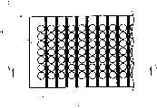
图1是表示有关本发明透镜平板的平面图。Fig. 1 is a plan view showing a lens plate related to the present invention.
图2是沿图1的A-A线剖面图。Fig. 2 is a sectional view along line A-A of Fig. 1 .
图3是表示用挤压成形法制成树脂平板的平面图和侧面图。Fig. 3 is a plan view and a side view showing a resin plate formed by extrusion molding.
图4是表示矩形槽内形成光吸收性膜的树脂平板平面图和侧面图。Fig. 4 is a plan view and a side view showing a resin plate on which a light-absorbing film is formed in a rectangular groove.
图5是表示用热轧压法在两面形成微小凸透镜后的一大张透镜平板平面图和侧面图。Fig. 5 is a plan view and a side view of a large sheet of lens plates after forming micro-convex lenses on both sides by the hot rolling method.
图6A是用热轧压法对树脂平板形成透镜列之前的树脂平板的局部放大剖面图。Fig. 6A is a partially enlarged cross-sectional view of a resin plate before forming lens arrays on the resin plate by hot rolling.
图6B是用热轧压法对树脂平板形成透镜列之后的树脂平板的局部放大剖面图。6B is a partially enlarged cross-sectional view of a resin plate after forming lens arrays on the resin plate by hot rolling.
图7是表示涂布黑色抗蚀剂以后状态的一大张透镜平板的平面图和侧面图。Fig. 7 is a plan view and a side view of a large lens plate showing the state after applying a black resist.
图8是表示切断状态的一大张透镜平板的平面图和侧面图。Fig. 8 is a plan view and a side view of a large lens plate showing a cut state.
图9A是表示用本发明透镜平板的图像传送装置例平面图。Fig. 9A is a plan view showing an example of an image transmission device using a lens plate of the present invention.
图9B是沿图9A的B-B线剖面图。Fig. 9B is a sectional view along line B-B of Fig. 9A.
图9C是图9A中所示图像传送装置的底面图。Fig. 9C is a bottom view of the image transfer device shown in Fig. 9A.
图9D是沿图9A的C-C线剖面图。Fig. 9D is a sectional view along line C-C of Fig. 9A.
图10A是表示用本发明透镜平板的图像传送装置另一例平面图。Fig. 10A is a plan view showing another example of the image transmission device using the lens plate of the present invention.
图10B是沿图10A的D-D线剖面图。Fig. 10B is a sectional view taken along line D-D of Fig. 10A.
图10C是图10A中所示图像传送装置的底面图。Fig. 10C is a bottom view of the image transfer device shown in Fig. 10A.
图10D是沿图10A的E-E线剖面图。Fig. 10D is a cross-sectional view along line E-E of Fig. 10A.
图11A是表示用本发明透镜平板的图像传送装置还有一例平面图。Fig. 11A is a plan view showing still another example of the image transmission device using the lens plate of the present invention.
图11B是沿图11A的F-F线剖面图。Fig. 11B is a sectional view taken along line F-F of Fig. 11A.
图11C是图11A中所示图像传送装置的底面图。Fig. 11C is a bottom view of the image transfer device shown in Fig. 11A.
图11D是沿图11A的G-G线剖面图。Fig. 11D is a cross-sectional view along line G-G of Fig. 11A.
图12A是表示图像传送装置的变形例图。Fig. 12A is a diagram showing a modified example of the image transmission device.
图12B是表示图像传送装置的变形例图。Fig. 12B is a diagram showing a modified example of the image transmission device.
图13是表示构成本发明正像透镜阵列的透镜平板平面图。Fig. 13 is a plan view showing a lens plate constituting the erecting lens array of the present invention.
图14是沿图13的H-H线剖面图。Fig. 14 is a sectional view along line H-H of Fig. 13 .
图15A是表示用正像透镜阵列在像面成像点光源的状态图。Fig. 15A is a diagram showing the state of imaging a point light source on an image plane with a erecting lens array.
图15B是说明产生透过光量不匀的状态图。Fig. 15B is a diagram illustrating a state in which unevenness in the amount of transmitted light occurs.
图15C是说明不产生透过光量不匀的状态图。Fig. 15C is a diagram illustrating a state in which unevenness in the amount of transmitted light does not occur.
图16是表示以透镜平板上1个微小凸透镜为中心,以透镜节距的2倍长度为半径的圆形区域内各个微小凸透镜的配置放大图。Fig. 16 is an enlarged diagram showing the disposition of each tiny convex lens in a circular area with a radius twice the length of the lens pitch, with one tiny convex lens on the lens plate as the center.
图17是表示放大像面上成像的点光源像图。Fig. 17 is a diagram showing a point light source image formed on an enlarged image plane.
图18是用正像透镜阵列把线状图像当作线状成像区域转送做的图像传送装置的表示一部分的例子的剖面图。Fig. 18 is a cross-sectional view showing a part of an example of an image transmission device for transferring a linear image as a linear imaging area by using a erecting lens array.
图19是表示图像传送装置另一例剖面图。Fig. 19 is a sectional view showing another example of the image transmission device.
图20是表示图像传送装置又有一例剖面图。Fig. 20 is a sectional view showing still another example of the image transmission device.
图21是说明在线状固体摄像器件上成像图像的状态图。Fig. 21 is a diagram illustrating a state of forming an image on a linear solid-state imaging device.
图22是表示以透镜平板上1个微小凸透镜为中心,以透镜节距的2倍长度为半径的圆形区域内各个微小凸透镜的配置放大图。Fig. 22 is an enlarged diagram showing the disposition of each tiny convex lens in a circular area with a radius twice the length of the lens pitch, centered on one tiny convex lens on the lens plate.
图23是表示放大线状成像区域的线状固体摄像器件上成像的像图。FIG. 23 is an image diagram showing an enlarged linear imaging region formed on a linear solid-state imaging device.
图24是透镜间的透镜平板上设置光吸收性膜时的说明图。Fig. 24 is an explanatory diagram when a light-absorbing film is provided on a lens plate between lenses.
图25是六方向最紧密填充排列的透镜间设置光吸收性膜时的说明图。Fig. 25 is an explanatory diagram when a light-absorbing film is provided between lenses arranged in the closest packing arrangement in six directions.
图26是说明光吸收性膜的配置例图。Fig. 26 is a diagram illustrating an arrangement example of a light-absorbing film.
图27是透镜间的透镜平板上设置遮光壁时的说明图。Fig. 27 is an explanatory view when a light-shielding wall is provided on a lens plate between lenses.
图28A是表示遮光壁的透镜平板平面方向形状的一例图。28A is a diagram showing an example of the shape of the light shielding wall in the plane direction of the lens plate.
图28B是表示遮光壁的透镜平板平面方向形状的一例图。28B is a diagram showing an example of the shape of the light shielding wall in the plane direction of the lens plate.
图28C是表示遮光壁的透镜平板平面方向形状的一例图。28C is a diagram showing an example of the shape of the light shielding wall in the plane direction of the lens plate.
图28D是表示遮光壁的透镜平板平面方向形状的一例图。28D is a diagram showing an example of the shape of the light shielding wall in the plane direction of the lens plate.
图28E是表示遮光壁的透镜平板平面方向形状的一例图。28E is a diagram showing an example of the shape of the light shielding wall in the plane direction of the lens plate.
图29是说明遮光壁的配置例图。Fig. 29 is a diagram illustrating an arrangement example of a light-shielding wall.
图30是说明遮光壁的配置例图。Fig. 30 is a diagram illustrating an arrangement example of a light-shielding wall.
图31是透镜平板上方设置遮光壁时的说明图。Fig. 31 is an explanatory diagram when a light-shielding wall is provided above the lens plate.
图32是透镜间设置遮光槽时的说明图。Fig. 32 is an explanatory diagram when light-shielding grooves are provided between lenses.
图33是说明遮光槽的配置例图。Fig. 33 is a diagram illustrating an arrangement example of light-shielding grooves.
图34是说明遮光槽的配置例图。Fig. 34 is a diagram illustrating an arrangement example of light-shielding grooves.
具体实施方式Detailed ways
其次,参照附图说明本发明的第1实施例。Next, a first embodiment of the present invention will be described with reference to the drawings.
图1是表示构成用于本发明立体图像和二维图像的空中显示装置、对屏幕的图像投影装置、在光电元件和感光体上成像图像的图像传送装置的正像透镜阵列的透镜平板平面图,图2是沿图1的A-A线剖面图。Fig. 1 is a lens plate plan view showing an erecting lens array constituting an aerial display device for a stereoscopic image and a two-dimensional image of the present invention, an image projection device to a screen, an image transmission device for imaging images on a photoelectric element and a photoreceptor, Fig. 2 is a sectional view along line A-A of Fig. 1 .
在透镜平板1上,与其短边方向互相平行,以规定的间隔,形成多条矩形槽3。矩形槽3成了,对于开口部的宽度深度深,长宽比高的槽。这里,形成了开口部宽度大约4倍,对透镜平板1的厚度约60%深度的槽。矩形槽3是以透镜平板1厚度的三分之一以上深度形成是令人满意的。On the
透镜平板1的材质,最好是热可塑性、光透过性高,吸水性低的。The material of the
本实施例中,用环链烯烃系树脂制造透镜平板。In this example, a lens plate was manufactured using a cycloolefin-based resin.
透镜平板1的材质,用丙烯系树脂也行。The material of the
而且,在透镜平板1方面,与短边方向互相平行,形成多个球面的微小凸透镜2的透镜列。微小凸透镜2的透镜列,把矩形槽3夹在中间以规定间隔形成。微小凸透镜2的平板平面方向的外形是圆形的。而且,微小凸透镜2,在透镜平板1的两面上形成,要使微小凸透镜2的光轴,配置在两面上一致。Further, on the
还有,本实施例中,设定微小凸透镜的形状为球面,非球面的形状也可以考虑。而且,微小凸透镜,除透镜平板的两面形成以外,单面形成的形式也可以考虑。微小凸透镜的排列是在平板的单面上形成的场合,矩形槽,在形成微小凸透镜排列的平面或与其对向的平面上形成是令人满意的,微小凸透镜排列在平板的两面形成的场合,矩形槽,在形成微小凸透镜排列的平面的至少另一方平面上形成是令人满意的。In addition, in this embodiment, the shape of the tiny convex lens is assumed to be a spherical surface, but an aspherical shape is also conceivable. In addition, the microconvex lens may be formed on one side of the lens plate instead of on both sides. When the arrangement of the tiny convex lenses is formed on one side of the flat plate, the rectangular groove is preferably formed on the plane on which the tiny convex lenses are arranged or on a plane opposite to it. In the case where the tiny convex lenses are arranged on both sides of the flat plate, It is desirable that the rectangular groove is formed on at least one of the planes on which the micro-convex lens array is formed.
而且,本实施例中,微小凸透镜的透镜列和矩形槽是对透镜平板的短边方向(对透镜平板的长边垂直的方向)形成,然而微小凸透镜的透镜列和矩形槽互相平行排列,相对透镜平板的长边倾斜方向形成也可以。And in the present embodiment, the lens row of tiny convex lens and rectangular groove are to form to the short side direction of lens flat plate (to the direction perpendicular to the long side of lens flat plate), yet the lens row of tiny convex lens and rectangular groove are arranged in parallel with each other, relatively The long side of the lens plate may be formed in an oblique direction.
在透镜平板1的表面,由硅化合物薄膜形成的低反射薄膜。低反射薄膜,是为了降低透镜平板的反射率的,可使用折射率比透镜平板低的材料。除了硅化合物薄膜以外也用氟系树脂膜。On the surface of the
而且,在透镜平板1的两面透镜形成区域外和微小凸透镜外周部,为了防止从透镜以外入射杂散光,由光吸收性膜形成掩蔽4和孔径光圈5。In addition, in order to prevent stray light from entering outside the double-sided lens formation area of the
还有,矩形槽3里,其底面和侧面也形成光吸收性膜。如上述那样,矩形槽3以透镜平板1的厚度三分之一以上深度来形成是令人满意的,因为有由光吸收性膜三分之一以上深度形成的遮光部分,倾斜入射的光当中,比透镜视角还宽广的角度入射的光,都能可靠地遮住。Also, in the
接着,说明有关按照本发明的透镜平板制造方法。Next, a method for manufacturing a lens plate according to the present invention will be described.
首先,用挤压成形法或注入成形法制作成为透镜平板基板的树脂平板。图3是表示用挤压成形法,制成树脂平板的平面图和侧面图。First, a resin plate to be a lens plate substrate is produced by extrusion molding or injection molding. Fig. 3 is a plan view and a side view showing a resin plate formed by extrusion molding.
在用于挤压成形的金属模上,为了可与树脂平板成形同时成形矩形槽3,形成矩形槽3的相反构造。树脂平板6成形为多个并列成形透镜平板的大小。In order to form the
其次,对矩形槽3形成用于防止杂散光的光吸收性膜。就光吸收膜来说例如,采用含有碳的黑颜色树脂涂料(抗蚀剂和油墨等)。光吸收性膜的形成,对矩形槽3的底面和侧面涂布黑色抗蚀剂。涂布到矩形槽3的黑色抗蚀剂,利用毛细管现象很容易实行。图4是表示矩形槽3里形成光吸收性膜后的树脂平板6平面图和侧面图。Next, a light-absorbing film for preventing stray light is formed on the
其次,对于矩形槽3里涂布了黑色抗蚀剂的树脂平板6,用热轧压法一并对两面形成微小凸透镜的排列,形成透镜平板多个并列形成后的一大张透镜平板。热轧压法是,用金属模夹住加热后的树脂平板,把金属模的形状复制到树脂平板上的树脂成形法。图5是表示用热轧压法对两面形成微小凸透镜后的一大张透镜平板7的平面图侧面图。Secondly, for the resin
而且,图6A是用热轧压法,在树脂平板上形成透镜列之前的树脂平板局部放大剖面,图6B用热轧压法,在树脂平板上形成透镜列之后的树脂平板局部放大剖面。6A is a partially enlarged section of a resin plate before forming lens arrays on the resin plate by hot rolling, and FIG. 6B is a partially enlarged section of the resin plate after forming lens arrays on the resin plate by hot rolling.
在矩形槽3里形成光吸收性膜之后,如以热轧压法形成微小凸透镜的排列,就用热和压力挤埋到槽内,如同透镜平板内部制成黑色遮光壁一样。即,就槽的空间而言,挤没了。因此,作为透镜平板的强度却增强了。After forming the light-absorbing film in the
其次,对于多个并列成形透镜平板的一大张透镜平板7,在透镜平板表面上形成由硅化合物薄膜制作的低反射薄膜。低反射薄膜是为降低透镜平板反射率的薄膜,除了硅化合物薄膜以外,氟系树脂膜等也可以使用。Next, for a
在透镜平板两面的透镜形成区域外和微小凸透镜外周部,形成用于防止透镜以外入射杂散光的光吸收性膜。在光吸收性膜方面,光反应性的材料,例如,使用含有碳的黑色抗蚀剂,通过光刻法,形成透镜形成区域外的掩蔽和微小凸透镜外周部的孔径光圈。图7表示涂布黑色抗蚀剂之后状态的一大张透镜平板7平面图和侧面图。A light-absorbing film for preventing stray light from entering other than the lens is formed outside the lens formation area on both surfaces of the lens plate and the peripheral portion of the micro-convex lens. In the light-absorbing film, a photoreactive material such as a black resist containing carbon is used to form a mask outside the lens forming region and an aperture stop at the outer peripheral portion of the microconvex lens by photolithography. FIG. 7 shows a plan view and a side view of a large sheet of
到这里的工序,在多个并列成形透镜平板的一大张透镜平板7的状态一并进行。The steps up to this point are collectively performed in a state where a
其次,切断一大张透镜平板7。图8是表示切断状态的一大张透镜平板7的平面图和侧面图。切断多个并列形成透镜平板的一大张透镜平板7,得到一个个透镜平板1。Next, a
其次,参照附图,说明采用组合本发明透镜平板形成的正像透镜阵列的图像传送装置。图9A~图9D是表示采用本发明透镜平板的图像传送装置的例图。图9A是平面图,图9B是沿图9A的B-B线剖面图,图9C是底面图,图9D是沿图9A的C-C线剖面图。Next, an image transmission device using a erecting lens array formed by combining a lens plate of the present invention will be described with reference to the accompanying drawings. 9A to 9D are diagrams showing an example of an image transmission device using the lens plate of the present invention. 9A is a plan view, FIG. 9B is a sectional view along line B-B of FIG. 9A , FIG. 9C is a bottom view, and FIG. 9D is a sectional view along line C-C of FIG. 9A .
正像透镜阵列,叠合2块以上透镜平板构成,图9A~图9D中,将两面形成微小凸透镜的2块透镜平板1叠合构成正像透镜阵列8。正像透镜阵列8装入透镜平板1的长方形透镜形成区域长边具有平行的狭缝状开口部10的隔壁构造体9内。该隔壁构造体9用光吸收性材料制造是令人满意的。The erecting lens array is formed by stacking two or more lens plates. In FIGS. The erecting lens array 8 is housed in the partition wall structure 9 having parallel slit-shaped openings 10 on the long sides of the rectangular lens formation region of the
隔壁构造体9带有狭缝状开口部10的开口宽度,设定为能够充分除去长方形透镜形成区域的短边方向发生杂散光的宽度。The opening width of the partition wall structure 9 with the slit-shaped opening 10 is set to a width sufficient to eliminate stray light generated in the short-side direction of the rectangular lens forming region.
还有,例如如图9A~图9D所示,构成正像透镜阵列的2块透镜平板(透镜面是4个面)之中,由图像传送装置的入射一侧看,对第1块的背面和2块的背面(出射面),都施行矩形槽加工,该矩形槽内形成为了防止杂散光的遮光壁(光吸收性膜)是令人满意的。Also, for example, as shown in FIGS. 9A to 9D , among the two lens plates (lens surfaces are four surfaces) constituting the erect image lens array, when viewed from the incident side of the image transmission device, the rear surface of the first block is Rectangular groove processing is performed on both the rear surface (exit surface) of the two pieces, and it is desirable to form a light-shielding wall (light-absorbing film) in the rectangular groove to prevent stray light.
该图像传送装置中,长方形透镜形成区域的长边方向发生的杂散光,借助于构成图像传送装置的透镜平板长方形透镜形成区域的短边方向所形成矩形槽更有效地予以除去。In this image transfer device, stray light generated in the long side direction of the rectangular lens forming area is more effectively removed by the rectangular grooves formed in the short side direction of the rectangular lens forming area of the lens plate constituting the image transfer device.
图10A~图10D是表示用本发明透镜平板的图像传送装置的里一例图。图10A是平面图,图10B是沿图10A的D-D线剖面图,图10C是底面图,图10D是沿图10A的E-E线剖面图。如图10A~图10D所示,在正像透镜阵列的入射一侧设置狭缝状开口部10的话,就能更有效地防止杂散光。10A to 10D are diagrams showing an example of an image transmission device using a lens plate of the present invention. 10A is a plan view, FIG. 10B is a cross-sectional view along line D-D of FIG. 10A, FIG. 10C is a bottom view, and FIG. 10D is a cross-sectional view along line E-E of FIG. 10A. As shown in FIGS. 10A to 10D , if the slit-shaped opening 10 is provided on the incident side of the erecting lens array, stray light can be prevented more effectively.
图11A~图11D表示用本发明透镜平板的图像传送装置的还有一例图。图11A是平面图,图11B是沿图11A的F-F线剖面图,图11C是底面图,图11D是沿图11A的G-G线剖面图。如图11A~图11D所示,在正像透镜阵列的入射一侧和出射一侧的两者都设置狭缝状开口部10也可以。11A to 11D show still another example of the image transmission device using the lens plate of the present invention. Fig. 11A is a plan view, Fig. 11B is a cross-sectional view along line F-F of Fig. 11A, Fig. 11C is a bottom view, and Fig. 11D is a cross-sectional view along line G-G of Fig. 11A. As shown in FIGS. 11A to 11D , slit-shaped openings 10 may be provided on both the incident side and the outgoing side of the erecting lens array.
图9A~图9D,图10A~图10D,图11A~图11D中,为了除去杂散光,在隔壁构造体9,设置与透镜形成区域的长边平行的狭缝状开口部10,然而如图12A所示,要以玻璃等透光性部件11覆盖狭缝状开口部10也行,如图12B所示,在隔壁构造体9,沿与透镜形成区域的长边平行的方向设置开口部,以印制狭缝的玻璃等透光性部件12覆盖开口部也行。通过以透光性部件覆盖开口部,能够防止尘土等附着到正像透镜阵列上。9A to 9D, 10A to 10D, and 11A to 11D, in order to remove stray light, the partition wall structure 9 is provided with a slit-shaped opening 10 parallel to the long side of the lens forming region, but as shown in FIG. As shown in 12A, it is also possible to cover the slit-shaped opening 10 with a light-transmitting
有关本发明第1实施例的透镜平板,在相邻微小凸透镜间形成的槽内形成光吸收性高的部位,因为这个部位构成除去杂散光的遮光壁,尤其能够有效地除去与该槽垂直方向产生的杂散光。Regarding the lens plate of the first embodiment of the present invention, a portion with high light absorption is formed in the groove formed between adjacent small convex lenses, because this portion constitutes a light-shielding wall for removing stray light, and can effectively remove light in the direction perpendicular to the groove. stray light produced.
而且,本发明透镜平板的制造方法,在槽成形的树脂平板上成形微小凸透镜后,用热和压力挤埋到作为槽的空间里,如同透镜平板内部制成遮光壁,因而能增强透镜平板的强度。And, the manufacturing method of lens flat plate of the present invention, after forming micro-convex lens on the resin flat plate of groove formation, squeeze and bury in the space as groove with heat and pressure, make light-shielding wall like the inside of lens flat plate, thereby can strengthen the lens flat plate strength.
还有,本发明的图像传送装置,借助于透镜平板上形成的槽,有效地除去长方形透镜形成区域的长边方向发生的杂散光,借助于隔壁构造体,有效地除去长方形透镜形成区域的短边方向发生的杂散光,因此能有效除去各个方向来的杂散光。Also, in the image transmission device of the present invention, the stray light generated in the long side direction of the rectangular lens forming region is effectively removed by means of the grooves formed on the lens plate, and the short side of the rectangular lens forming region is effectively removed by means of the partition wall structure. The stray light generated in the side direction can effectively remove the stray light from all directions.
接着,参照附图,说明有关本发明第2实施例。Next, a second embodiment of the present invention will be described with reference to the drawings.
图13表示构成用于在光电元件或感光体上成像图像的图像传送装置的正像透镜阵列的透镜平板平面图,图14是沿图13的H-H线剖面图。13 is a plan view of a lens plate constituting an erecting lens array of an image transfer device for forming an image on a photoelectric element or a photoreceptor, and FIG. 14 is a cross-sectional view taken along line H-H in FIG. 13 .
透镜平板21的材质,以热可塑性,光透过性高、吸水性低的材料是令人满意的。本实施例中,采用环链烯烃系树脂,用注入成形法,制作板厚2.29mm的透镜平板。透镜平板21的材质,用丙烯系树脂也行。The material of the lens plate 21 is preferably a thermoplastic material with high light transmittance and low water absorption. In this example, a lens plate having a thickness of 2.29 mm was produced by injection molding using a cycloolefin resin. The material of the lens plate 21 may be acrylic resin.
微小凸透镜22是透镜直径0.35mm,曲率半径0.66mm球面形状的透镜,透镜节距0.45mm,在六方向排列透镜的六方向排列中,要在透镜阵列21的两面上形成,使得微小凸透镜22的光轴、配置对两面一致。The tiny convex lens 22 is a lens with a lens diameter of 0.35mm and a spherical shape with a radius of curvature of 0.66mm. The lens pitch is 0.45mm. In the six-direction arrangement of lenses arranged in six directions, it should be formed on both sides of the lens array 21, so that the tiny convex lens 22 The optical axis, arrangement are consistent on both sides.
还有,本实施例中,微小凸透镜的形状设为球面,然而也可以考虑非球面的形状。而且,微小凸透镜,除透镜平板的两面都形成的形式以外,也可以考虑单面形成的形式。In addition, in this embodiment, the shape of the minute convex lens is spherical, but an aspheric shape is also conceivable. In addition, the microconvex lens may be formed on one side of the lens plate in addition to the form formed on both sides of the lens plate.
微小凸透镜的排列方向,对透镜形成区域的长边方向倾斜15°。重像出现的方向为透镜的排列方向,因而使微小凸透镜的排列方向和透镜形成区域的长边方向(主扫描方向)方向不能为同一方向。The arrangement direction of the micro-convex lenses was inclined by 15° with respect to the long-side direction of the lens forming region. The direction in which double images appear is the alignment direction of the lenses, so the alignment direction of the tiny convex lenses and the long side direction (main scanning direction) of the lens forming region cannot be in the same direction.
至少2块对向配置这种树脂制作的透镜平板构成正像透镜。At least two lens plates made of this resin are arranged facing each other to form a erecting lens.
图15A表示从一个光源(读出对象)出射的光线,通过至少的2块对向配置透镜平板30的正像透镜阵列32的光线可读出区A并入射线状固体摄像器件38的状态。如图15B所示,正像透镜阵列的光线可读出区A内,不包括1个以上微小凸透镜31的全体场合,发生透过光量不匀,如图15c所示,包括1个以上微小凸透镜31的全体场合,不发生透光量不匀。所以,图15A中,为了降低透过光量不匀,从1个光源出射的光线的,在正像透镜阵列32的光线可取得区A内,包括1个以上微小凸透镜的全体。入射角(孔径角)设为±6°,工作距离设为6.9mm,从1个光源出射光线的,在正像透镜阵列32的光线可取得区A的半径设为0.73mm。为了降低透过光量不匀,需要光线可取得区(由透镜的入射角与工作距离的关系决定)的面积是光线可取得区内各个透镜面积以上。FIG. 15A shows a state where light emitted from one light source (readout target) enters a radial solid-
而且,微小凸透镜以规定透镜节距有规则排列的透镜形成区域长边方向的长度(主扫描方向长)是从光源出射光线的光线可取得区的主走查方向长度以上,透镜形成区域短边方向的长度(副扫描方向长)为光线可取得区的副扫描方向长度以上是令人满意的。Moreover, the length of the long side direction of the lens forming region (long in the main scanning direction) in which the micro convex lenses are regularly arranged at a predetermined lens pitch is greater than or equal to the length in the main scanning direction of the light beam obtaining region of the light emitted from the light source, and the short side of the lens forming region It is satisfactory that the length in the direction (long in the sub-scanning direction) is equal to or greater than the length in the sub-scanning direction of the ray-accepting region.
图16表示放大透镜平板上的1个微小凸透镜作为中心而有透镜节距的2倍长度为半径的圆形区域内各个微小凸透镜31的配置图,图17表示扩大像面上成像的点光源像33的图。Fig. 16 shows a tiny convex lens on the magnifying lens flat plate as the center and has 2 times the length of the lens pitch as the disposition diagram of each tiny
用对向透镜平板配置的正像透镜阵列,在像面上成像点光源的场合,重像出现的方向是透镜的排列方向。点光源像离像面上重像出现点的距离,由透镜节距和工作距离决定。图16中,1个的微小凸透镜作为中心而以透镜节距2倍长度为半径的圆形区域内,联结区域内微小凸透镜31的中心所得到的直线方向,偏离透镜阵列的长边方向(主扫描方向)15°。When a point light source is imaged on the image plane with a erecting lens array arranged opposite to the lens plate, the direction in which double images appear is the direction in which the lenses are arranged. The distance between the point light source image and the point where the double image appears on the image plane is determined by the lens pitch and working distance. In Fig. 16, 1 tiny convex lens is as the center and in the circular area with the
把微小凸透镜以六方向排列配置的场合,联结上述区域内透镜中心所得到的直线方向,对于透镜阵列的长边方向(主扫描方向)和0°(平行),30°,60°,90°(直角)不一致是令人满意的。尤其成15°角度是令人满意的。When the micro-convex lenses are arranged in six directions, the linear direction obtained by connecting the center of the lens in the above-mentioned area is 30°, 60°, 90° for the long side direction (main scanning direction) of the lens array and 0° (parallel) (Right angle) inconsistency is desirable. Especially an angle of 15° is satisfactory.
还有,把微小凸透镜成矩阵式状排列的长度方向排列的场合,设长度方向排列透镜的透镜节距长的一方为长节距,设短的一方为短节距,把1个微小凸透镜作为中心而以(长节距2+矩节矩2)1/2为半径的区域内,联结区域内透镜中心所得到的直线方向就是与透镜阵列长边方向(主扫描方向)偏离。Also, in the case of arraying the microconvex lenses in a matrix in the longitudinal direction, the longer pitch of the lenses arranged in the longitudinal direction is defined as the long pitch, and the shorter one is defined as the short pitch, and one microconvex lens is used as In the area with a radius of (long pitch2 + square pitch2 )1/2 , the direction of the straight line obtained by connecting the center of the lens in the area deviates from the long side direction (main scanning direction) of the lens array.
图18是表示用上述的正像透镜阵列把线状图像传送给线状成像区域的图像传输装置的局部例子剖面图。正像透镜阵列32,由对向配置在两面形成微小凸透镜的2块透镜平板30而构成,并装入正像透镜阵列32的像点侧,在与正像透镜阵列32的长边方向平行方向有狭缝状开口部34的隔壁构造体36a内。在传送线上图像的线状成像区域,设置至少1列CCD的线状固体撮像器件38。线状固体摄像器件38占用区域的大小为线状成像区域以上是令人满意的。狭缝状开口部34a,尽可能限度靠近固体撮像器件是令人满意的。Fig. 18 is a cross-sectional view showing a partial example of an image transmission device that transmits a linear image to a linear imaging region using the above-mentioned erecting lens array. The positive
图19是表示图像传送装置另一例剖面图,正像透镜阵列32装入物点侧有狭缝状开口部34b的隔壁构造体36b内。除物点侧有狭缝状开口部的以外,都和图18同样。物点侧工作距离内配置狭缝状开口部的话,就能更有效地减轻重像。狭缝状开口部34b尽可能限度靠近光源是令人满意的。FIG. 19 is a cross-sectional view showing another example of the image transfer device. The erecting
图20是表示图像传送装置的还有一例的剖面图,将正像透镜阵列32装入在像点侧有狭缝状开口部34a的同时,装入物点侧有狭缝状开口部34b的隔壁构造体36c内。除像点侧和物点侧有狭缝状开口部以外,都与图18和图19同样。如图20所示,物点侧工作距离内和像点侧工作距离内的双方都设置狭缝状开口部也行。狭缝状开口部34a尽可能限度靠近固体摄像器件是令人满意的,狭缝状开口部34b尽可能限度靠近光源是令人满意的。20 is a cross-sectional view showing another example of an image transfer device, in which the erecting
即,本发明,物点侧工作距离内和/或像点工作距离内,不需要具备有为了除去光线的狭缝状开口部的间壁墙构造体是令人满意的。That is, in the present invention, it is preferable that the partition wall structure does not need to have a slit-shaped opening for removing light within the working distance on the object point side and/or within the working distance on the image point.
狭缝状开口部顶端部分的剖面形状,如图18,图19,图20所示,具有斜坡。如图19所示,狭缝状开口部顶端一部分的剖面形状是透镜侧好像变宽了那样的构造就行。最好,对如图20所示的隔壁构造体的像点侧所设置的狭缝状开口部34a那样,要使光入射方向侧缩小。狭缝状开口部顶端部分斜坡角度,对成像没有影响的范围内,只要作成不发生散射的角度就行,尤其认为45度以下是令人满意的。狭缝状开口部,与隔壁构造体成为一体,或另外设置也可以。狭缝状开口部的长边方向,和线状成像区域的主扫描方向平行是令人满意的。狭缝的位置和宽度,在线状图像的重像不进入线状成像区域的范围内适当设计。The cross-sectional shape of the tip portion of the slit-shaped opening has a slope as shown in FIGS. 18 , 19 , and 20 . As shown in FIG. 19 , the cross-sectional shape of a part of the tip of the slit-shaped opening may be such that the lens side becomes wider. It is preferable that the light incident direction side be narrowed like the slit-shaped opening 34a provided on the image point side of the partition wall structure shown in FIG. 20 . The slope angle at the top end of the slit-shaped opening is not affected as far as imaging is concerned, as long as scattering does not occur. In particular, 45 degrees or less is considered satisfactory. The slit-shaped opening may be integrated with the partition wall structure or provided separately. It is desirable that the longitudinal direction of the slit-shaped opening is parallel to the main scanning direction of the linear imaging area. The position and width of the slit are appropriately designed within a range in which the double image of the linear image does not enter the linear imaging area.
还有,在这里,作为读出对象的图像假定为线状图像,然而不管是点状图像还是面状图像也都行。狭缝,尤其面状图像的场合有效果。点状图像和线状图像的场合,在物点侧·像点侧设置不设置狭缝状开口部都行,但设置狭缝状开口部是令人满意的。面状图像的场合,需要在物点侧设置狭缝状开口部。对像点侧而言,不管设置还是不设置都行,但设置的是令人满意的。Here, the image to be read is assumed to be a linear image, but it may be a dot image or a planar image. Slits are especially effective for planar images. In the case of dot-like images and line-like images, there may be no need to provide slit-shaped openings on the object point side and image point side, but it is preferable to provide slit-shaped openings. In the case of a planar image, it is necessary to provide a slit-shaped opening on the object point side. For the image point side, it doesn't matter whether it is set or not set, but the set is satisfactory.
有狭缝状开口部的隔壁构造体,为了除去光学系统内反射的光线,内壁上具有光吸收性功能是令人满意的。或者用光吸收性材料构成隔壁构造体本身是令人满意的。而且,用黑色的隔壁材料当作隔壁构造体,对隔壁材料表面进行微细凹凸加工,使之有光吸收性是令人满意的。In the partition wall structure having a slit-shaped opening, it is desirable that the inner wall has a light-absorbing function in order to remove light reflected in the optical system. Alternatively, it is preferable to constitute the partition wall structure itself with a light-absorbing material. Furthermore, it is desirable to use a black partition wall material as the partition wall structure, and finely roughen the surface of the partition wall material to impart light absorption.
正像透镜阵列的透镜形成区域的短边方向长度(副扫描方向长)设为狭缝状开口部的短边方向长度(副扫描方向长)以上,狭缝状开口部短边方向的长度,设为固体摄像器件的短边方向长度(副扫描方向长)以上。The length in the short side direction (long in the sub-scanning direction) of the lens forming region of the positive image lens array is set to be greater than or equal to the length in the short side direction (long in the sub-scanning direction) of the slit-shaped opening, and the length in the short-side direction of the slit-shaped opening is, The length in the short-side direction (long in the sub-scanning direction) of the solid-state imaging device is greater than or equal to that.
实际上,将狭缝状开口部的短边方向长度设为0.5mm,对狭缝状开口部、安装固体摄像器件公差也考虑之后,透镜形成区域的短边方向长度设为2.0mm。Actually, the length in the short direction of the slit-shaped opening is set to 0.5 mm, and the length in the short-side direction of the lens formation region is set to 2.0 mm after considering the tolerance of the slit-shaped opening and mounting of the solid-state imaging device.
还有,正像透镜阵列的透镜形成区域的长边方向长度(主扫描方向长)设为狭缝状开口部的长边方向长度(主扫描方向长)以上,狭缝状开口部的长边方向长度设为固体摄像器件的长边方向长度(主扫描方向长)以上。In addition, the length in the longitudinal direction (long in the main scanning direction) of the lens forming region of the positive image lens array is set to be greater than or equal to the length in the longitudinal direction (long in the main scanning direction) of the slit-shaped opening, and the length of the long side of the slit-shaped opening The length in the direction is equal to or greater than the length in the longitudinal direction (long in the main scanning direction) of the solid-state imaging device.
而且,正像透镜阵列的工作距离长度,规定为从正像透镜阵列的透镜面到狭缝状开口部的距离的狭缝深度以上。Furthermore, the working distance length of the erecting lens array is defined to be equal to or greater than the slit depth of the distance from the lens surface of the erecting lens array to the slit-shaped opening.
对线状固体摄像器件38而言,传输单色线状图像的场合,可用1列排列的CCD,传输彩色线状图像的场合,可用3列排列的CCD。As for the linear solid-
图21是说明在线状固体摄像器件38上成像图像的状态图,图22是表示正像透镜阵列的1个微小凸透镜作为中心而以透镜节距2倍长度为半径的圆形区域内各个微小凸透镜31的配置放大图,图23是表示在线状成像区域的线状固体摄像器件38上成像的像点和重像出现的点扩大图。Fig. 21 is a diagram illustrating the state of forming an image on the linear solid-
通过正像透镜阵列,向图像摄像器件取得图像的场合,为了减少入射固体摄像器件的杂散光,要这样配置微小凸透镜,使得微小凸透镜的排列方向和固体摄像器件的长边方向不是同一方向。When an image is obtained from an image pickup device through a positive lens array, in order to reduce stray light incident on the solid-state imaging device, the arrangement of the micro-convex lenses is such that the arrangement direction of the micro-convex lenses is not in the same direction as the long-side direction of the solid-state imaging device.
以六方向排列配置微小凸透镜的场合,在把1个微小凸透镜作为中心,以透镜节距2倍长度为半径的圆形区域内,使联结微小凸透镜中心得到的直线方向,和固体撮像器件的长边方向不是同一方向。When the micro-convex lenses are arranged in six directions, in a circular area with one micro-convex lens as the center and twice the length of the lens pitch as the radius, make the straight line direction obtained by connecting the centers of the micro-convex lenses and the length of the solid-state imaging device The edge directions are not in the same direction.
长方排列的场合,在把1个微小凸透镜作为中心而以(长节距2+短节距2)1/2长度为半径圆形区域内,使联结微小凸透镜的中心得到的直线方向,和固体摄像器件的长边方向不是同一方向。In the case of a rectangular arrangement, in a circular area with a radius of (long pitch2 + short pitch2 )1/2 with one tiny convex lens as the center, the straight line direction obtained by connecting the centers of the tiny convex lenses, and The long-side directions of the solid-state imaging device are not in the same direction.
而且,如上述一样,以六方向排列配置微小凸透镜的场合,在把1个微小凸透镜作为中心而以透镜节距的2倍长度为半径的圆形区域内,或是长方排列的场合,把1个微小凸透镜作为中心而以(长节距2+短节距2)1/2长度为半径圆形区域内,需要至少固体摄像器件的长边方向和透镜的排列方向不一致,还有,在上述的区域内,使固体摄像器件内没有成像重像,即,固体摄像器件的短边方向长度的1/2长度比从沿着固体摄像器件长边方向的中心线到重像出现的像点最短距离长度还短是需要的。And, as mentioned above, in the case of arranging micro-convex lenses in six directions, in a circular area with one micro-convex lens as the center and twice the length of the lens pitch as a radius, or in the case of a rectangular arrangement, the In a circular area with a radius of (long pitch2 + short pitch2 )1/2 as the center of one tiny convex lens, at least the long side direction of the solid-state imaging device and the arrangement direction of the lenses need to be inconsistent, and, in In the above-mentioned area, there is no imaging double image in the solid-state imaging device, that is, the 1/2 length ratio of the short-side direction length of the solid-state imaging device is from the center line along the long-side direction of the solid-state imaging device to the image point where the double image occurs The shortest distance length is also required.
实际制造的图像传送装置中,线状图像、正像等倍透镜阵列、狭缝和固体摄像器件的组合,观察向固体摄像器件的取得结果的话,区别量子化噪声与杂散光的影响就是不可能同一水准。In the image transmission device actually manufactured, it is impossible to distinguish the influence of quantization noise and stray light when observing the result obtained from the combination of a linear image, a positive equal-magnification lens array, a slit, and a solid-state imaging device. same level.
研究点光源成像特性,然而应设置固体摄像器件地点的杂散光量,减少到2/1000。To study the imaging characteristics of point light sources, however, the amount of stray light at the location of the solid-state imaging device should be set to reduce to 2/1000.
图24是透镜直径0.35mm、透镜节距0.45mm,、透镜间的透镜平板上设置光吸收性膜(遮光膜)40时的说明图,图25是透镜直径0.45mm、透镜节距0.45mm,六方向最紧密填充排列(互相靠近的排列)之后设置光吸收性膜(遮光膜)40时的说明图。Fig. 24 is an explanatory diagram when the lens diameter is 0.35 mm and the lens pitch is 0.45 mm, and the light-absorbing film (shading film) 40 is arranged on the lens plate between the lenses. Fig. 25 is a lens diameter of 0.45 mm and a lens pitch of 0.45 mm. An explanatory diagram of the case where the light-absorbing film (light-shielding film) 40 is provided after the six-direction closest packing arrangement (arrangement close to each other).
构成正像透镜阵列的透镜平板的透镜面各自从光源入射侧设为[1]面、[2]面、[3]面、…[N]面的场合,对偶数号码面设置光吸收膜40是令人满意的,对奇数号面不管设立还是不设立都行,最好是设置的。图26是说明透镜面具有[1]~[4]面的透镜面时的配置光吸收性膜的例图。When the lens planes of the lens plates constituting the erect lens array are [1] plane, [2] plane, [3] plane, ... [N] plane from the light incident side, light absorbing
读出至少2块对向透镜平板配置的正像透镜阵列光学系统的场合,从1个固体摄像器件(CCD)对透镜面引垂直线为光轴的话,除从光轴上物点发出光线以外的光线(杂散光)也入射到固体摄像器件。In the case of reading a erecting lens array optical system with at least two opposing lens plates, if a solid-state imaging device (CCD) draws a vertical line to the lens surface as the optical axis, in addition to emitting light from the object point on the optical axis The light (stray light) also enters the solid-state imaging device.
该杂散光,对正像透镜阵列的排列(方向、节距),和孔径角有依赖关系,从节距狭小方向会入射更多杂散光,孔径角缩小的话,就从靠近光轴部分入射杂散光。靠近光轴部分来的杂散光越多给予像的影响越大,随着离开光轴而杂散光给予像的影响减少。The stray light is dependent on the arrangement (direction, pitch) of the erecting lens array and the aperture angle. More stray light will be incident from the narrower pitch direction. If the aperture angle is reduced, the stray light will be incident from the part close to the optical axis. astigmatism. The more stray light near the optical axis, the greater the influence on the image, and the farther away from the optical axis, the less the influence of stray light on the image.
为了在正像等倍光学系统得到良好的成像性能,需要以某些方法除去杂散光。本发明的图像传送装置中,都用狭缝状开口部除去比较地靠近光轴部分来的杂散光,以在透镜间的透镜平板上设置的遮光膜除去来自较远部分的杂散光。In order to obtain good imaging performance in the erect image equal magnification optical system, it is necessary to remove stray light in some way. In the image transmission device of the present invention, the slit-shaped openings are used to remove stray light relatively close to the optical axis, and the light-shielding film provided on the lens plate between the lenses removes stray light from the far part.
透镜的孔径角宽广的场合,重像的出现角度只是广角,只要除去广角范围的重像就行,即使只有遮光膜,也能除去重像。另一方面,透镜的孔径角狭小的场合,重像的出现角度从狭角变成到广角,因广大范围的光进入固体撮像器件,以狭缝状开口部除去窄角范围的重像,以遮光膜除去广角范围的重像,就好。所以,孔径角狭小的场合,设置狭缝状开口部和遮光膜的两者是令人满意的。例如,孔径角是10°的场合即使只有遮光膜也行,孔径角是6°的场合设置狭缝状开口部和遮光膜的两者是令人满意的。When the aperture angle of the lens is wide, ghosting occurs only at the wide-angle angle, and ghosting in the wide-angle range can be eliminated, even with a light-shielding film. On the other hand, when the aperture angle of the lens is narrow, the appearance angle of the ghost image changes from a narrow angle to a wide angle. Since a wide range of light enters the solid-state imaging device, the ghost in the narrow angle range is removed by the slit-shaped opening, and The light-shielding film removes ghosting in the wide-angle range, just fine. Therefore, when the aperture angle is narrow, it is preferable to provide both the slit-shaped opening and the light-shielding film. For example, when the aperture angle is 10°, only the light-shielding film is sufficient, and when the aperture angle is 6°, it is preferable to provide both the slit-shaped opening and the light-shielding film.
装置的设计等理由,没有设置狭缝状开口部的场合,由于提高遮光膜高度,也能得到和狭缝大致同等的效果。Even when the slit-shaped opening is not provided due to the design of the device, the effect substantially equivalent to that of the slit can be obtained by increasing the height of the light-shielding film.
图27是透镜间的透镜平板上设置遮光壁时的说明图。至少1块透镜平板上设置光吸收性的遮光壁50是令人满意的。Fig. 27 is an explanatory view when a light-shielding wall is provided on a lens plate between lenses. It is desirable to provide a light-absorptive light-shielding wall 50 on at least one lens plate.
对透镜直径0.35mm、透镜节距0.42mm的透镜,各自的透镜上设为孔径直径0.35mm、节距0.42mm,设置遮光壁50,其高度(从透镜顶部到遮光壁顶端部的高度)为0.2mm以上。如设置这样的遮光壁,透镜顶点入射的光线与透镜光轴的交角为45度以下,因此可以比与透镜光轴比交角45度大的光线,即除去离开光轴部分来的杂散光。根据透镜孔径角,因为杂散光的入射角度变化,遮光壁的高度应按与透镜孔径角的关系适当设计就行。较好是0.15~2.0mm,最好是0.2~2.0mm。For lenses with a lens diameter of 0.35mm and a lens pitch of 0.42mm, the respective lenses are set to have an aperture diameter of 0.35mm and a pitch of 0.42mm, and a light-shielding wall 50 is set. The height (from the top of the lens to the top of the light-shielding wall) is 0.2mm or more. If such a light-shielding wall is installed, the angle between the incident light at the vertex of the lens and the optical axis of the lens is less than 45 degrees, so the light rays with a larger angle than 45 degrees with the optical axis of the lens can be removed, that is, the stray light from the part away from the optical axis can be removed. According to the lens aperture angle, because the incident angle of stray light changes, the height of the light-shielding wall should be properly designed in relation to the lens aperture angle. Preferably, it is 0.15-2.0 mm, Most preferably, it is 0.2-2.0 mm.
遮光壁的透镜平板平面方向形状,除图28A所示的矩形状、图28B所示的六角形状(蜂窝状)、图28C所示的圆形、图28D和图28E所示的透镜以外全部作为遮光壁形状等。从光源入射侧设定透镜面各自为[1]面、[2]面、[3]面、…[N]面的场合,在[1]面设置遮光壁50是令人满意的。在设置遮光壁50和光吸收性膜40两者的场合,距光源入射侧最近[1]面一定设置遮光壁50,距光源入射侧最远的[N]面一定设置光吸收性膜40。关于[I]和[N]面之间的面,可在[2M(M=1、2、3、…)]面和[2M+1]面的哪面一方设置光吸收性膜40。代替[N]面的光吸收性膜40而设置遮光壁50也行。图29是[1]~[4]面有透镜面的场合的遮光壁50和光吸收性膜40的配置例说明图,图30是把[4]面的光吸收性膜40替换为遮光壁50时的配置例说明图。还有,遮光壁是和光吸收性膜相同的材料也行。The shape of the lens plate plane direction of the light-shielding wall, except the rectangular shape shown in FIG. 28A, the hexagonal shape (honeycomb shape) shown in FIG. 28B, the circle shown in FIG. 28C, and the lens shown in FIG. The shape of the shading wall, etc. When the lens surfaces from the light incident side are [1], [2], [3], . When both the light-shielding wall 50 and the light-absorbing
图31是透镜平板上方设置遮光壁时的说明图。遮光壁50不与透镜平板接触,即使在透镜平板的上方也能得到同样的效果。遮光壁不与透镜平板接触的场合,透镜的节距和遮光壁的节距也可以不同。遮光壁不与透镜平板接触的场合,从更广范围角度入射光,就需要比接触的场合还要高的遮光壁(需要至少2倍以上的高度)。而且,不接触的场合,由于造成干涉条纹发生的问题,所以最好是接触的场合为好。Fig. 31 is an explanatory diagram when a light-shielding wall is provided above the lens plate. The light shielding wall 50 is not in contact with the lens plate, and the same effect can be obtained even if it is above the lens plate. When the light shielding wall is not in contact with the lens plate, the pitch of the lenses and the pitch of the light shielding wall may be different. When the light-shielding wall is not in contact with the lens plate, light is incident from a wider range of angles, and the light-shielding wall needs to be higher (at least twice the height) than when it is in contact. In addition, since there is a problem of interference fringes in the case of non-contact, the case of contact is preferable.
正像等倍光学系统的光量透射率,和透镜的孔径角也有依赖关系,然而遮光壁的高度为数百微米以上的话,除去距光轴远的杂散光外,也能除去距光轴近的杂散光,即使在上述隔壁构造体没有设置狭缝开口部,也能得到良好的图像。The light transmittance of the positive image equal-magnification optical system also depends on the aperture angle of the lens. However, if the height of the light-shielding wall is more than several hundred microns, it can eliminate the stray light far from the optical axis and the light near the optical axis. For stray light, a good image can be obtained even if no slit opening is provided in the above-mentioned partition wall structure.
其次,说明有关遮光壁的制作方法。制作遮光壁的第1实施例是,用厚膜印制形成遮光壁的。首先,在树脂基体材料上涂布规定厚度(20~100μm)的光感光性黑色树脂涂料(油墨或光刻胶),使之干燥直至表面无粘性。干燥是在树脂基体材料软化温度以下进行的。Next, a method of manufacturing the light-shielding wall will be described. The first embodiment of making the light-shielding wall is to form the light-shielding wall by thick film printing. First, apply a photosensitive black resin coating (ink or photoresist) with a specified thickness (20-100 μm) on the resin base material, and let it dry until the surface is non-sticky. Drying is carried out below the softening temperature of the resin matrix material.
其次,在印制图案区域外设置标记之后,使用掩模进行曝光。Next, after setting marks outside the printed pattern area, exposure is performed using a mask.
重复这些工序,层叠黑色树脂涂料形成所希望的厚度。随后,进行显影和后烘焙(通过加热使其硬化)。本实施例中,1次部分的厚度设为70μm,通过3次重复形成了210μm的壁。黑色树脂是为减少表面反射,因而表面为皱纹状态(凹凸状态)是令人满意的。尤其内壁部分为皱纹状态是令人满意的。By repeating these steps, the black resin paint is laminated to a desired thickness. Subsequently, development and post-baking (hardening by heating) are performed. In this example, the thickness of the primary portion was set to 70 μm, and a wall of 210 μm was formed by three repetitions. The black resin is for reducing surface reflection, so it is desirable that the surface is in a wrinkled state (concave-convex state). In particular, it is desirable that the inner wall portion is in a corrugated state.
制作遮光壁的第2实施例是,形成黑色的树脂加强筋形成遮光壁。In the second embodiment of making the light-shielding wall, black resin ribs are formed to form the light-shielding wall.
首先,用注入成形法,按以下顺序制作黑颜色的树脂加强筋。在成型中,采用由有剑山状突起的剑山状板、有与突起对应的洞孔的多孔板、和平板构成的金属模。首先,一边对多孔板的孔插入剑山状板的突起一边在剑山状板上安置多孔板,进而其上安置了平板。First, use the injection molding method to make black resin ribs in the following steps. For molding, a metal mold composed of a kendo-shaped plate having kendo-shaped protrusions, a perforated plate having holes corresponding to the protrusions, and a flat plate is used. First, the perforated plate was set on the gable plate while inserting the protrusions of the gable plate into the holes of the perforated plate, and then the flat plate was set thereon.
其次,从对平板设置的多个针状栅注入树脂,把树脂填充到多孔板与平板间,加以冷却。冷却后卸下平板,随后,从剑山状板剥离成型品。内壁为皱纹状态的场合,成型后为了容易脱模,在突起设置10度以下的拔模斜度就行。透镜上安置得到的成型品,成为带有遮光壁的透镜阵列。Next, resin is injected from a plurality of needle grids provided on the flat plate, and the resin is filled between the perforated plate and the flat plate, and cooled. After cooling, the flat plate was removed, and then, the molded product was peeled off from the kangaroo-shaped plate. When the inner wall is in a wrinkled state, it is sufficient to set a draft angle of 10 degrees or less on the protrusions for easy release after molding. The obtained molded product is placed on the lens to form a lens array with a light-shielding wall.
突起上设置拔模斜度的场合,如把树脂加强筋薄的一方作为透镜侧的话,就能很有效地除去杂散光。而且,如把树脂加强筋厚的一方作为透镜侧,就能提高透光量。树脂加强筋的孔形,不管六角形(蜂窝状)或是矩形什么样的形状也都行。When the protrusion is provided with a draft angle, if the thinner side of the resin rib is used as the lens side, stray light can be effectively eliminated. Moreover, if the thicker side of the resin rib is used as the lens side, the amount of light transmission can be increased. The hole shape of the resin rib can be hexagonal (honeycomb) or rectangular.
第1实施例子和第2的实施使用的树脂热膨胀系数,也都和用于透镜的树脂热膨胀系数接近是所希望的。而且,10-5(1/℃)数量级的热膨胀系数是令人满意的。It is also desirable that the thermal expansion coefficients of the resins used in the first embodiment and the second embodiment are close to those of the resins used for lenses. Also, a coefficient of thermal expansion on the order of 10-5 (1/°C) is satisfactory.
而且,除了第1和第2实施例以外,规定厚的黑色软片等也可以用紫外线激光加工制作加强筋。Furthermore, besides the first and second embodiments, a black film having a predetermined thickness, etc., can also be processed by ultraviolet laser to produce ribs.
图32是透镜直径0.35mm、透镜节距0.45mm,透镜间设置遮光槽时的说明图。在至少1块透镜平板的单面或两面,为了除去不需要的光线,透镜间设置光吸收性的遮光槽60是令人满意的。遮光槽的深度,也深的为好,较好的是透镜平板厚度的30%以上,更好的是50%以上,最好是60%以上。Fig. 32 is an explanatory diagram when the lens diameter is 0.35 mm, the lens pitch is 0.45 mm, and light-shielding grooves are provided between the lenses. It is desirable to provide light-absorptive light-shielding
在从光源入射侧设定透镜面各自为[1]面、[2]面、[3]面、…[N]面的场合,对奇数号面或偶数号码面设置遮光槽。图33是说明[1]~[4]面之中对奇数号面设遮光槽时的光吸收性膜配置例图。对奇数号面设遮光槽60时距光源入射侧在最远的[N]面上一定设置光吸收性40,除[N]面以外的奇数号面上,不管设或是不设光吸收性膜也都行。图34是说明[1]~[4]面内之中对偶数号面设遮光槽时的光吸收性膜配置例图。对偶数号面设遮光槽60时,[1]面上一定设光吸收性膜40,除[1]面以外的奇数号面上,不管设或是不设光吸收性膜也都行。When the lens surfaces from the light incident side are set as [1] plane, [2] plane, [3] plane, ... [N] plane, light-shielding grooves are provided on odd-numbered or even-numbered planes. Fig. 33 is a diagram illustrating an arrangement example of a light-absorbing film when light-shielding grooves are provided on odd-numbered surfaces among [1] to [4] surfaces. When the light-shielding
在图33和图34中,代替遮光膜40而形成遮光槽60也行,而且全部的面都设置遮光槽60也行。In FIGS. 33 and 34 , instead of the light-shielding
而且,在上述的实施例中,为了除去不需要给固体摄像器件的波长光线,要使透镜平板内具有紫外线截止功能或红外线截止功能,或是光路中具有紫外线截止滤波器或红外线截止滤波器也可以。Moreover, in the above-mentioned embodiment, in order to remove the wavelength light that does not need to be given to the solid-state imaging device, it is necessary to have an ultraviolet cutoff function or an infrared cutoff function in the lens plate, or to have an ultraviolet cutoff filter or an infrared cutoff filter in the optical path. Can.
而且,关于狭缝状开口部、遮光膜、遮光壁和遮光槽的组合,在用于读出面状图像的图像传送装置中,一种最佳组合是狭缝状开口部、遮光膜、最近光源入射侧的[1]面上设了遮光壁(或遮光槽)的组合(以下,称作组合(1))。除[1]面以外全部面都设遮光膜的场合,可对全部透镜孔径角除去重像。代替遮光膜而制作遮光壁或遮光槽也行。再一种最佳组合是,遮光膜、最近光源入射侧的[1]面上设了遮光壁(或遮光槽)的组合(以下,称作组合(2))。这个组合,孔径角宽广的场合是令人满意的。代替遮光膜而制作遮光壁或遮光槽也行。无论组合(1)和组合(2),具备隔壁构造体并把正像透镜阵列装入隔壁构造体内是令人满意的。Furthermore, regarding the combination of the slit-shaped opening, the light-shielding film, the light-shielding wall, and the light-shielding groove, in an image transfer device for reading out a planar image, an optimal combination is a slit-shaped opening, a light-shielding film, and recently A combination (hereinafter referred to as combination (1)) in which a light-shielding wall (or light-shielding groove) is provided on the surface [1] on the incident side of the light source. When the light-shielding film is provided on all surfaces except [1], ghosting can be eliminated for all lens aperture angles. Instead of the light-shielding film, it is also possible to make a light-shielding wall or a light-shielding groove. Another optimal combination is a combination (hereinafter referred to as combination (2)) of a light-shielding film and a light-shielding wall (or light-shielding groove) on the surface [1] of the incident side of the nearest light source. This combination is satisfactory when the aperture angle is wide. Instead of the light-shielding film, it is also possible to make a light-shielding wall or a light-shielding groove. Regardless of combination (1) and combination (2), it is satisfactory to have a partition wall structure and incorporate a erecting lens array in the partition wall structure.
本发明第2实施例的正像透镜阵列,要使微小凸透镜的排列方向和透镜形成区域的长边方向不是同一方向,能够充分除去杂散光。In the erecting lens array according to the second embodiment of the present invention, the arrangement direction of the micro-convex lenses and the long-side direction of the lens formation region are not in the same direction, so that stray light can be sufficiently removed.
而且,第2实施例的图像传送装置,固体摄像器件的长边方向和透镜的排列方向不是同一方向,还有固体撮像器件的区域内不会结成重像,因而能够充分除去重像。Furthermore, in the image transmission device of the second embodiment, the longitudinal direction of the solid-state imaging device and the arrangement direction of the lenses are not in the same direction, and ghost images are not formed in the region of the solid-state imaging device, so ghost images can be sufficiently eliminated.
Claims (30)
Applications Claiming Priority (8)
| Application Number | Priority Date | Filing Date | Title |
|---|---|---|---|
| JP270061/2003 | 2003-07-01 | ||
| JP2003270056 | 2003-07-01 | ||
| JP270056/2003 | 2003-07-01 | ||
| JP2003270061 | 2003-07-01 | ||
| JP2004088334AJP2005037884A (en) | 2003-07-01 | 2004-03-25 | Lens plate, its manufacturing method, and image transmitting apparatus |
| JP088334/2004 | 2004-03-25 | ||
| JP2004111678AJP4132055B2 (en) | 2003-07-01 | 2004-04-06 | Image reading device |
| JP111678/2004 | 2004-04-06 |
Related Child Applications (1)
| Application Number | Title | Priority Date | Filing Date |
|---|---|---|---|
| CN 200710096729DivisionCN101034167A (en) | 2003-07-01 | 2004-07-01 | Image transfer device |
Publications (1)
| Publication Number | Publication Date |
|---|---|
| CN1576896Atrue CN1576896A (en) | 2005-02-09 |
Family
ID=33556552
Family Applications (1)
| Application Number | Title | Priority Date | Filing Date |
|---|---|---|---|
| CNA2004100634145APendingCN1576896A (en) | 2003-07-01 | 2004-07-01 | Lens plate, manufacturing method thereof, and image transmission device |
Country Status (4)
| Country | Link |
|---|---|
| US (3) | US7116484B2 (en) |
| KR (1) | KR20050004021A (en) |
| CN (1) | CN1576896A (en) |
| TW (1) | TW200506418A (en) |
Cited By (11)
| Publication number | Priority date | Publication date | Assignee | Title |
|---|---|---|---|---|
| CN101351765B (en)* | 2005-10-24 | 2010-08-25 | Rpo私人有限公司 | Improved optical elements for waveguide-based optical touch screens and method therefor |
| CN105812625A (en)* | 2014-12-30 | 2016-07-27 | 深圳超多维光电子有限公司 | Micro lens array imaging device and imaging method |
| CN106331439A (en)* | 2015-07-10 | 2017-01-11 | 深圳超多维光电子有限公司 | Micro lens array imaging device and imaging method |
| CN109188574A (en)* | 2018-09-25 | 2019-01-11 | 豪威光电子科技(上海)有限公司 | A kind of optical lens and forming method thereof |
| CN112166353A (en)* | 2018-05-22 | 2021-01-01 | 3M创新有限公司 | Optical film with light controlling edge |
| WO2021233096A1 (en)* | 2020-05-22 | 2021-11-25 | 北京芯海视界三维科技有限公司 | Manufacturing method for lenticular grating |
| CN113703181A (en)* | 2020-05-22 | 2021-11-26 | 北京芯海视界三维科技有限公司 | Lens grating and manufacturing method thereof |
| CN113703185A (en)* | 2020-05-22 | 2021-11-26 | 北京芯海视界三维科技有限公司 | Method for manufacturing lenticular grating |
| CN113703180A (en)* | 2020-05-22 | 2021-11-26 | 北京芯海视界三维科技有限公司 | Method for manufacturing lenticular grating |
| CN113703186A (en)* | 2020-05-22 | 2021-11-26 | 北京芯海视界三维科技有限公司 | Lens, grating, display panel and display |
| CN116125569A (en)* | 2023-04-14 | 2023-05-16 | 福建福特科光电股份有限公司 | Preparation method of microlens array based on nanoimprint lithography |
Families Citing this family (46)
| Publication number | Priority date | Publication date | Assignee | Title |
|---|---|---|---|---|
| US7002749B2 (en)* | 1997-07-08 | 2006-02-21 | Kremen Stanley H | Modular integral magnifier |
| US20050195598A1 (en)* | 2003-02-07 | 2005-09-08 | Dancs Imre J. | Projecting light and images from a device |
| JP2005525897A (en) | 2002-05-13 | 2005-09-02 | エス.シー. ジョンソン アンド サン、インコーポレイテッド | Harmonious fragrance, light and sound generation |
| TW200506418A (en)* | 2003-07-01 | 2005-02-16 | Nippon Sheet Glass Co Ltd | Lens plate, its manufacturing method, and image transmitting apparatus |
| JP3983206B2 (en)* | 2003-08-21 | 2007-09-26 | 日本板硝子株式会社 | Image reading device |
| JP3831373B2 (en)* | 2003-10-31 | 2006-10-11 | シャープ株式会社 | Sheet detecting apparatus and image forming apparatus |
| KR100608011B1 (en)* | 2004-11-03 | 2006-08-02 | 삼성전자주식회사 | Image display |
| USD541922S1 (en) | 2005-03-31 | 2007-05-01 | S.C. Johnson & Son, Inc. | Diffuser |
| US7281811B2 (en)* | 2005-03-31 | 2007-10-16 | S. C. Johnson & Son, Inc. | Multi-clarity lenses |
| US7589340B2 (en) | 2005-03-31 | 2009-09-15 | S.C. Johnson & Son, Inc. | System for detecting a container or contents of the container |
| US7643734B2 (en)* | 2005-03-31 | 2010-01-05 | S.C. Johnson & Son, Inc. | Bottle eject mechanism |
| USD542400S1 (en) | 2005-03-31 | 2007-05-08 | S.C. Johnson & Son, Inc. | Diffuser |
| DE602006003095D1 (en)* | 2005-05-26 | 2008-11-20 | Bahadur Maneesh | FOR SHAPING SMALL FORMS |
| WO2007032048A1 (en)* | 2005-09-12 | 2007-03-22 | Tadahiro Ohmi | Process for producing transparent member and plastic member |
| WO2007040246A1 (en)* | 2005-10-06 | 2007-04-12 | Nippon Sheet Glass Company, Limited | Image forming optical system, image reader using image forming optical system, and image writer |
| MY144041A (en)* | 2006-01-17 | 2011-07-29 | Dow Corning | Thermally stable transparent silicone resin compositions and methods for their preparation and use |
| US7551830B2 (en)* | 2006-02-01 | 2009-06-23 | Dow Corning Corporation | Impact resistant optical waveguide and method of manufacture thereof |
| WO2007100445A2 (en)* | 2006-02-24 | 2007-09-07 | Dow Corning Corporation | Light emitting device encapsulated with silicones and curable silicone compositions for preparing the silicones |
| KR100730212B1 (en)* | 2006-03-28 | 2007-06-19 | 삼성에스디아이 주식회사 | Filter assembly and plasma display device having same |
| US8013289B2 (en) | 2006-11-15 | 2011-09-06 | Ether Precision, Inc. | Lens array block for image capturing unit and methods of fabrication |
| JP2010044139A (en)* | 2008-08-11 | 2010-02-25 | Seiko Epson Corp | Lens array and line head |
| US7813043B2 (en) | 2008-08-15 | 2010-10-12 | Ether Precision, Inc. | Lens assembly and method of manufacture |
| US8090250B2 (en)* | 2009-06-23 | 2012-01-03 | Ether Precision, Inc. | Imaging device with focus offset compensation |
| US20120134028A1 (en)* | 2009-08-13 | 2012-05-31 | Fujifilm Corporation | Wafer level lens, production method of wafer level lens, and imaging unit |
| US9295463B2 (en)* | 2009-10-08 | 2016-03-29 | Covidien Lp | Shape memory fasteners and method of use |
| CN102193114A (en)* | 2010-03-04 | 2011-09-21 | 株式会社东芝 | Erect equal-magnification lens array |
| WO2011121662A1 (en) | 2010-03-31 | 2011-10-06 | パナソニック株式会社 | Display panel device and method for manufacturing display panel device |
| JP5918938B2 (en)* | 2011-06-30 | 2016-05-18 | 日本板硝子株式会社 | Lens array plate and erecting equal-magnification lens array plate manufacturing method |
| CN103975436B (en) | 2011-07-19 | 2019-05-10 | 新加坡恒立私人有限公司 | Methods of making passive optical devices and devices containing the same |
| JP2013104993A (en)* | 2011-11-14 | 2013-05-30 | Seiko Epson Corp | Screen, and method of manufacturing screen |
| GB2509764B (en)* | 2013-01-14 | 2018-09-12 | Kaleido Tech Aps | A lens array and a method of making a lens array |
| DE102013209246B4 (en)* | 2013-05-17 | 2019-07-18 | Fraunhofer-Gesellschaft zur Förderung der angewandten Forschung e.V. | A method of making a false light suppression structure and apparatus therewith |
| US10368852B2 (en)* | 2013-06-26 | 2019-08-06 | Strait Access Technologies Holdings (Pty) Ltd | Orientation device for use in mitral valve repair |
| US9176261B2 (en)* | 2014-02-17 | 2015-11-03 | Genius Electronic Optical Co., Ltd. | Optical lens assembly, array type lens module and method of making the array type lens module |
| KR102189819B1 (en)* | 2014-09-01 | 2020-12-14 | 삼성디스플레이 주식회사 | Organic light emitting display apparatus |
| WO2017106209A1 (en) | 2015-12-13 | 2017-06-22 | GenXComm, Inc. | Interference cancellation methods and apparatus |
| US10257746B2 (en)* | 2016-07-16 | 2019-04-09 | GenXComm, Inc. | Interference cancellation methods and apparatus |
| JP7370713B2 (en) | 2019-03-07 | 2023-10-30 | 株式会社小糸製作所 | optical unit |
| US10727945B1 (en)* | 2019-07-15 | 2020-07-28 | GenXComm, Inc. | Efficiently combining multiple taps of an optical filter |
| US11539394B2 (en) | 2019-10-29 | 2022-12-27 | GenXComm, Inc. | Self-interference mitigation in in-band full-duplex communication systems |
| US11796737B2 (en) | 2020-08-10 | 2023-10-24 | GenXComm, Inc. | Co-manufacturing of silicon-on-insulator waveguides and silicon nitride waveguides for hybrid photonic integrated circuits |
| US12001065B1 (en) | 2020-11-12 | 2024-06-04 | ORCA Computing Limited | Photonics package with tunable liquid crystal lens |
| EP4040040B1 (en)* | 2021-02-09 | 2023-12-20 | ZKW Group GmbH | Projection device for a motor vehicle headlamp |
| US12057873B2 (en) | 2021-02-18 | 2024-08-06 | GenXComm, Inc. | Maximizing efficiency of communication systems with self-interference cancellation subsystems |
| EP4331120A1 (en) | 2021-04-29 | 2024-03-06 | Genxcomm, Inc. | Self-interference cancellation subsystems for mesh network nodes |
| CA3234722A1 (en) | 2021-10-25 | 2023-05-04 | Farzad Mokhtari-Koushyar | Hybrid photonic integrated circuits for ultra-low phase noise signal generators |
Family Cites Families (16)
| Publication number | Priority date | Publication date | Assignee | Title |
|---|---|---|---|---|
| DE1203115B (en)* | 1964-11-20 | 1965-10-14 | Agfa Gevaert Ag | Exposure arrangement for copiers |
| GB1240655A (en)* | 1967-11-06 | 1971-07-28 | Fawkham Dev Ltd | Improvements relating to a method of and apparatus for treating particulate material |
| US4168900A (en)* | 1978-04-24 | 1979-09-25 | Minolta Camera Kabushiki Kaisha | Compact erect optical imaging copier system and method |
| JPS56168621A (en)* | 1980-05-29 | 1981-12-24 | Minolta Camera Co Ltd | Projection system |
| JPS57161825A (en)* | 1981-03-31 | 1982-10-05 | Canon Inc | Compound eye projecting device |
| US4496984A (en)* | 1982-11-18 | 1985-01-29 | Xerox Corporation | Raster input/output scanner |
| US5270859A (en)* | 1992-01-30 | 1993-12-14 | United Technologies Corporation | Optical instrument with micro-lenses |
| US6133986A (en)* | 1996-02-28 | 2000-10-17 | Johnson; Kenneth C. | Microlens scanner for microlithography and wide-field confocal microscopy |
| JP3453492B2 (en)* | 1997-05-13 | 2003-10-06 | キヤノン株式会社 | Image forming apparatus and printer head |
| US6462794B1 (en)* | 1998-10-14 | 2002-10-08 | Hitachi, Ltd. | Image forming unit, enlarging unit, optical parts, and image display apparatus having these components |
| JP4131891B2 (en)* | 1999-09-03 | 2008-08-13 | ローム株式会社 | Lens array and method for manufacturing lens array |
| KR20080094053A (en)* | 2001-06-01 | 2008-10-22 | 도판 인사츠 가부시키가이샤 | Microlens Sheets, Projection Screens and Displays |
| US6766817B2 (en)* | 2001-07-25 | 2004-07-27 | Tubarc Technologies, Llc | Fluid conduction utilizing a reversible unsaturated siphon with tubarc porosity action |
| TWI224209B (en)* | 2001-11-01 | 2004-11-21 | Nippon Sheet Glass Co Ltd | Erect image resin lens array and the manufacture thereof |
| JP2004070268A (en)* | 2002-06-12 | 2004-03-04 | Nippon Sheet Glass Co Ltd | Erecting and unmagnifying lens array |
| TW200506418A (en)* | 2003-07-01 | 2005-02-16 | Nippon Sheet Glass Co Ltd | Lens plate, its manufacturing method, and image transmitting apparatus |
- 2004
- 2004-06-16TWTW093117271Apatent/TW200506418A/enunknown
- 2004-06-28KRKR1020040048883Apatent/KR20050004021A/ennot_activeWithdrawn
- 2004-06-28USUS10/878,580patent/US7116484B2/ennot_activeExpired - Lifetime
- 2004-07-01CNCNA2004100634145Apatent/CN1576896A/enactivePending
- 2006
- 2006-07-27USUS11/494,314patent/US7242526B2/ennot_activeExpired - Lifetime
- 2007
- 2007-06-07USUS11/810,871patent/US20070241469A1/ennot_activeAbandoned
Cited By (14)
| Publication number | Priority date | Publication date | Assignee | Title |
|---|---|---|---|---|
| CN101351765B (en)* | 2005-10-24 | 2010-08-25 | Rpo私人有限公司 | Improved optical elements for waveguide-based optical touch screens and method therefor |
| CN105812625A (en)* | 2014-12-30 | 2016-07-27 | 深圳超多维光电子有限公司 | Micro lens array imaging device and imaging method |
| CN105812625B (en)* | 2014-12-30 | 2019-03-19 | 深圳超多维科技有限公司 | Microlens array imaging device and imaging method |
| CN106331439A (en)* | 2015-07-10 | 2017-01-11 | 深圳超多维光电子有限公司 | Micro lens array imaging device and imaging method |
| CN112166353A (en)* | 2018-05-22 | 2021-01-01 | 3M创新有限公司 | Optical film with light controlling edge |
| CN109188574A (en)* | 2018-09-25 | 2019-01-11 | 豪威光电子科技(上海)有限公司 | A kind of optical lens and forming method thereof |
| WO2021233096A1 (en)* | 2020-05-22 | 2021-11-25 | 北京芯海视界三维科技有限公司 | Manufacturing method for lenticular grating |
| CN113703181A (en)* | 2020-05-22 | 2021-11-26 | 北京芯海视界三维科技有限公司 | Lens grating and manufacturing method thereof |
| CN113703185A (en)* | 2020-05-22 | 2021-11-26 | 北京芯海视界三维科技有限公司 | Method for manufacturing lenticular grating |
| CN113703184A (en)* | 2020-05-22 | 2021-11-26 | 北京芯海视界三维科技有限公司 | Method for manufacturing lenticular grating |
| CN113703180A (en)* | 2020-05-22 | 2021-11-26 | 北京芯海视界三维科技有限公司 | Method for manufacturing lenticular grating |
| CN113703186A (en)* | 2020-05-22 | 2021-11-26 | 北京芯海视界三维科技有限公司 | Lens, grating, display panel and display |
| CN116125569A (en)* | 2023-04-14 | 2023-05-16 | 福建福特科光电股份有限公司 | Preparation method of microlens array based on nanoimprint lithography |
| CN116125569B (en)* | 2023-04-14 | 2023-09-12 | 福建福特科光电股份有限公司 | Preparation method of microlens array based on nanoimprint lithography |
Also Published As
| Publication number | Publication date |
|---|---|
| US20070241469A1 (en) | 2007-10-18 |
| US7242526B2 (en) | 2007-07-10 |
| US20060262412A1 (en) | 2006-11-23 |
| KR20050004021A (en) | 2005-01-12 |
| US20050002105A1 (en) | 2005-01-06 |
| TW200506418A (en) | 2005-02-16 |
| US7116484B2 (en) | 2006-10-03 |
Similar Documents
| Publication | Publication Date | Title |
|---|---|---|
| CN1576896A (en) | Lens plate, manufacturing method thereof, and image transmission device | |
| US5121254A (en) | Image transmitting element and process for producing photo-shield spacer plate used therein | |
| JP5009209B2 (en) | Wafer-like optical device and manufacturing method thereof, electronic element wafer module, sensor wafer module, electronic element module, sensor module, and electronic information device | |
| JP4116224B2 (en) | Manufacturing method of lens array | |
| TW200410042A (en) | Transmissive type screen and rear type projector | |
| CN1229652C (en) | Imaging optical device | |
| CN1269018A (en) | Microlens array substrate, its manufacturing method and display | |
| CN1271458C (en) | Method for making substrate of microlens and exposure optical system of microlens | |
| CN1497268A (en) | Method for manufacturing microlens matrix and projection type liquid crystal display device | |
| JP2011223190A (en) | Image reader and optical module used therein | |
| CN1463388A (en) | Microlens sheet and projection screen | |
| CN1618039A (en) | Transmissive screen and projection display device | |
| CN1885129A (en) | Lighting apparatus and display apparatus | |
| CN1955787A (en) | Spatial light modulation device and projector | |
| CN1924619A (en) | Optical unit and microlens array substrate and method of manufacturing the same | |
| CN1783504A (en) | Solid-state imaging device and method for manufacturing the same | |
| JP4132055B2 (en) | Image reading device | |
| CN1918903A (en) | Camera module | |
| JP5918938B2 (en) | Lens array plate and erecting equal-magnification lens array plate manufacturing method | |
| CN1782750A (en) | Optical component and method of manufacture of optical component | |
| CN1839347A (en) | Fresnel lens sheet, transmissive screen and rear projection display device | |
| US5046159A (en) | Image transmitting element and process for producing same | |
| US5163117A (en) | Image transmitting element comprising an array of photo-transmissible holes | |
| CN1488992A (en) | Thru-screen and rear-projection projectors | |
| JP4116182B2 (en) | Lens array assembly and optical apparatus using the same |
Legal Events
| Date | Code | Title | Description |
|---|---|---|---|
| C06 | Publication | ||
| PB01 | Publication | ||
| C10 | Entry into substantive examination | ||
| SE01 | Entry into force of request for substantive examination | ||
| C02 | Deemed withdrawal of patent application after publication (patent law 2001) | ||
| WD01 | Invention patent application deemed withdrawn after publication |