CN1576143A - Locating and clamping apparatus - Google Patents
Locating and clamping apparatusDownload PDFInfo
- Publication number
- CN1576143A CN1576143ACNA200410062933XACN200410062933ACN1576143ACN 1576143 ACN1576143 ACN 1576143ACN A200410062933X ACNA200410062933X ACN A200410062933XACN 200410062933 ACN200410062933 ACN 200410062933ACN 1576143 ACN1576143 ACN 1576143A
- Authority
- CN
- China
- Prior art keywords
- clamping
- hole
- burr
- pin
- positioning
- Prior art date
- Legal status (The legal status is an assumption and is not a legal conclusion. Google has not performed a legal analysis and makes no representation as to the accuracy of the status listed.)
- Granted
Links
Images


Classifications
- B—PERFORMING OPERATIONS; TRANSPORTING
- B62—LAND VEHICLES FOR TRAVELLING OTHERWISE THAN ON RAILS
- B62D—MOTOR VEHICLES; TRAILERS
- B62D65/00—Designing, manufacturing, e.g. assembling, facilitating disassembly, or structurally modifying motor vehicles or trailers, not otherwise provided for
- B62D65/02—Joining sub-units or components to, or positioning sub-units or components with respect to, body shell or other sub-units or components
- B62D65/18—Transportation, conveyor or haulage systems specially adapted for motor vehicle or trailer assembly lines
- B—PERFORMING OPERATIONS; TRANSPORTING
- B25—HAND TOOLS; PORTABLE POWER-DRIVEN TOOLS; MANIPULATORS
- B25B—TOOLS OR BENCH DEVICES NOT OTHERWISE PROVIDED FOR, FOR FASTENING, CONNECTING, DISENGAGING OR HOLDING
- B25B5/00—Clamps
- B25B5/06—Arrangements for positively actuating jaws
- B25B5/08—Arrangements for positively actuating jaws using cams
- B25B5/087—Arrangements for positively actuating jaws using cams actuated by a hydraulic or pneumatic piston
- B—PERFORMING OPERATIONS; TRANSPORTING
- B25—HAND TOOLS; PORTABLE POWER-DRIVEN TOOLS; MANIPULATORS
- B25B—TOOLS OR BENCH DEVICES NOT OTHERWISE PROVIDED FOR, FOR FASTENING, CONNECTING, DISENGAGING OR HOLDING
- B25B5/00—Clamps
- B25B5/16—Details, e.g. jaws, jaw attachments
- B—PERFORMING OPERATIONS; TRANSPORTING
- B60—VEHICLES IN GENERAL
- B60Y—INDEXING SCHEME RELATING TO ASPECTS CROSS-CUTTING VEHICLE TECHNOLOGY
- B60Y2304/00—Optimising design; Manufacturing; Testing
- B60Y2304/07—Facilitating assembling or mounting
Landscapes
- Engineering & Computer Science (AREA)
- Mechanical Engineering (AREA)
- Manufacturing & Machinery (AREA)
- Chemical & Material Sciences (AREA)
- Combustion & Propulsion (AREA)
- Transportation (AREA)
- Jigs For Machine Tools (AREA)
- Automatic Assembly (AREA)
- Automobile Manufacture Line, Endless Track Vehicle, Trailer (AREA)
Abstract
Translated fromChinese
Description
Translated fromChinese技术领域technical field
本发明涉及在汽车的车体组装工艺等中,通过定位销确定板状工件的位置,并夹持被定位的工件的定位夹持装置。The present invention relates to a positioning and clamping device for determining the position of a plate-shaped workpiece by positioning pins and clamping the positioned workpiece in the automobile body assembly process and the like.
背景技术Background technique
图14A,图14B中,显示了根据特开2002-337770号公报(特许文献1)记载的以往的定位夹持装置。特许文献1的定位夹持装置以定位销11伸出的状态形成夹持主体10,同时,在定位销11的下方的外侧形成底座面12。在夹持主体10的纵向孔13以及定位销11的中空孔中,可自由移动地设置夹持臂,在夹持主体10的纵向孔13内可往复移动地设置直动型致动器17的输出部件,通过连接销连接夹持臂和输出部件。使支点销19穿过形成于夹持臂上的导向狭缝18,支点销19由夹持主体10的支点销支承孔支承。在图14A中,显示了将定位销插入板状工件24的定位孔内,通过夹持臂的顶端部23和底座面12夹持工件24的状态。FIG. 14A and FIG. 14B show a conventional positioning clamping device described in JP-A-2002-337770 (Patent Document 1). In the positioning and clamping device of Patent Document 1, a
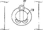
在夹持工件24的状态下进行焊接作业时,在焊接中飞散出的毛刺(熔渣或金属颗粒)会从连通定位销11的中空孔和外部的开口部22进入夹持主体10的纵向槽13内。在特许文献1的定位夹持装置中,为了去除进入夹持主体10内的毛刺,要定期分解和清扫定位夹持装置。但是,由于形成使夹持主体10的纵向孔13与外部连通的毛刺排出孔25,以便无需分解就能从毛刺排出孔排出毛刺,因此,在图14A中记载了毛刺排出孔25。另外,未在特许文献1中明示的内容如图14B所示,为了防止支点销19的脱落,应使支点销19的两端从支点销支承孔向外部伸出,使通孔贯穿于支点销19的两端部,使开口销27通过该通孔,并使开口销27的顶端弯曲。When the welding operation is carried out in the state of clamping the
在图14A,图14B所示的现有技术中,在定位夹持装置的使用条件下,由于通过毛刺排出孔25,毛刺会侵入并存积在夹持主体10的纵向孔13内,因此,要频繁进行中断焊接等作业以排出毛刺的操作,故作业效率降低。另外,在拆除支点销以分解定位夹持装置时,必须准备工具以整直开口销27的弯曲部,从而抽出开口销27,因此,作业效率降低。In the prior art shown in Fig. 14A and Fig. 14B, under the conditions of use of the positioning and clamping device, burrs will invade and accumulate in the
发明内容Contents of the invention
本发明的第1个目的在于在定位夹持装置中,防止毛刺从毛刺排出孔侵入夹持主体内,第2个目的在于在定位夹持装置分解时能够简单地拆除支点销。The first object of the present invention is to prevent burrs from intruding into the holding body through the burr discharge hole in the positioning clamp device, and the second purpose is to easily remove the fulcrum pin when the positioning clamp device is disassembled.
作为第一种结构,本发明提供了一种定位夹持装置,其中,在夹持主体上以伸出的状态形成定位销的同时,在定位销的外侧形成底座面,在夹持主体的纵向孔以及定位销的中空孔中,可以自由转动地设置夹持臂,在夹持主体的纵向孔内,可往复运动地设置直动型致动器的输出部件,通过连接销连接夹持臂和输出部件,使支点销贯穿形成于夹持臂中的导向狭缝,通过夹持主体的支点销支承孔来支承支点销,形成连通夹持主体的纵向孔和外部的毛刺排出孔,在夹持臂的顶端部和底座面之间夹持工件,其中:As a first structure, the present invention provides a positioning clamping device, wherein, while the positioning pin is formed on the clamping body in a protruding state, a base surface is formed on the outside of the positioning pin, and a seat surface is formed on the longitudinal direction of the clamping body. In the hollow hole of the hole and the positioning pin, the clamping arm can be freely rotated, and in the longitudinal hole of the clamping body, the output part of the direct-acting actuator can be set reciprocatingly, and the clamping arm and the The output part makes the fulcrum pin pass through the guide slit formed in the clamping arm, supports the fulcrum pin through the fulcrum pin supporting hole of the clamping main body, and forms a longitudinal hole connecting the clamping main body and an external burr discharge hole. The workpiece is clamped between the top end of the arm and the base surface, wherein:
毛刺防护盖可自由拆卸地安装在毛刺排出孔的排出端,在装有毛刺防护盖时,毛刺排出孔被封闭,在拆除毛刺防护盖时,毛刺排出孔被打开。The burr protection cover can be freely detachably installed on the discharge end of the burr discharge hole. When the burr protection cover is installed, the burr discharge hole is closed, and when the burr protection cover is removed, the burr discharge hole is opened.
作为第二种结构,本发明提供了一种定位夹持装置,其中,在夹持主体上以伸出的状态形成定位销的同时,在定位销的外侧形成底座面,在夹持主体的纵向孔以及定位销的中空孔中,可以自由转动地设置夹持臂,在夹持主体的纵向孔内,可往复运动地设置直动型致动器的输出部件,通过连接销连接夹持臂和输出部件,使支点销穿过形成于夹持臂中的导向狭缝,通过夹持主体的支点销支承孔来支承支点销,形成连通夹持主体的纵向孔和外部的毛刺排出孔,在夹持臂的顶端部和底座面之间夹持工件,其中:As a second structure, the present invention provides a positioning and clamping device, wherein, while the positioning pin is formed on the clamping body in a protruding state, a seating surface is formed on the outside of the positioning pin, and a seat surface is formed on the longitudinal direction of the clamping body. In the hollow hole of the hole and the positioning pin, the clamping arm can be freely rotated, and in the longitudinal hole of the clamping body, the output part of the direct-acting actuator can be set reciprocatingly, and the clamping arm and the The output part makes the fulcrum pin pass through the guide slit formed in the clamping arm, supports the fulcrum pin through the fulcrum pin support hole of the clamping main body, forms the longitudinal hole communicating with the clamping main body and the external burr discharge hole, and in the clamping The workpiece is clamped between the top end of the holding arm and the base surface, wherein:
在支点销支承孔的外侧端形成纵向槽,在纵向槽的两个侧壁上形成滑动槽,在两个滑动槽中装有盖,通过盖防止支点销脱落。A longitudinal groove is formed at the outer end of the supporting hole of the fulcrum pin, and sliding grooves are formed on two side walls of the longitudinal groove. Covers are housed in the two sliding grooves, and the fulcrum pins are prevented from coming off by the covers.
作为第三种结构,本发明提供了一种定位夹持装置,其中,在夹持主体上以伸出的状态形成定位销的同时,在定位销的外侧形成底座面,在夹持主体的纵向孔以及定位销的中空孔中,可以自由转动地设置夹持臂,在夹持主体的纵向孔内,可往复运动地设置直动型致动器的输出部件,通过连接销连接夹持臂和输出部件,使支点销穿过形成于夹持臂中的导向狭缝,通过夹持主体的支点销支承孔来支承支点销,形成连通夹持主体的纵向孔和外部的毛刺排出孔,在夹持臂的顶端部和底座面之间夹持工件,其中:As a third structure, the present invention provides a positioning and clamping device, wherein, while the positioning pin is formed on the clamping body in a protruding state, a seat surface is formed on the outside of the positioning pin, and in the longitudinal direction of the clamping body In the hollow hole of the hole and the positioning pin, the clamping arm can be freely rotated, and in the longitudinal hole of the clamping body, the output part of the direct-acting actuator can be set reciprocatingly, and the clamping arm and the The output part makes the fulcrum pin pass through the guide slit formed in the clamping arm, supports the fulcrum pin through the fulcrum pin support hole of the clamping main body, forms the longitudinal hole communicating with the clamping main body and the external burr discharge hole, and in the clamping The workpiece is clamped between the top end of the holding arm and the base surface, wherein:
在夹持主体的侧面形成连通毛刺排出孔以及支点销支承孔的纵向槽,在纵向槽的两个侧壁形成滑动槽,在两个滑动槽上装有具有上部盖和下部盖的毛刺防护盖,通过毛刺防护盖的上部盖防止支点销脱落,通过毛刺防护盖的下部盖开闭毛刺排出孔。A longitudinal groove connecting the burr discharge hole and the fulcrum pin support hole is formed on the side of the clamping body, sliding grooves are formed on the two side walls of the longitudinal groove, and a burr protection cover with an upper cover and a lower cover is installed on the two sliding grooves. The upper cover of the burr protection cover prevents the fulcrum pin from falling off, and the lower cover of the burr protection cover opens and closes the burr discharge hole.
作为第四种结构。本发明在第3种结构中,可相互转动地连接毛刺防护盖的上部盖和下部盖,在上部盖的两侧形成纵向延伸的弹性凸起,同时,在下部盖的两侧形成卡合凸起,上部盖的弹性凸起可滑动地与所述两个滑动槽结合,下部盖的卡合凸起可以与滑动槽结合。as a fourth structure. In the third structure of the present invention, the upper cover and the lower cover of the burr protection cover are rotatably connected to each other, elastic protrusions extending longitudinally are formed on both sides of the upper cover, and engaging protrusions are formed on both sides of the lower cover. The elastic protrusions of the upper cover can be slidably combined with the two sliding grooves, and the engaging protrusions of the lower cover can be combined with the sliding grooves.
在本发明的第2种和第3种结构中,纵向槽的两个侧壁为在形成支点销支承孔的壁的两侧,呈直角连接设置的2个壁(未形成滑动槽的壁)。In the second and third structures of the present invention, the two side walls of the longitudinal groove are two walls connected at right angles on both sides of the wall forming the supporting hole of the fulcrum pin (the wall not forming the sliding groove) .
在本发明的第1,3,4种结构中,毛刺防护盖可自由装卸地安装在夹持主体的毛刺排出孔的排出端,在装有毛刺防护盖时封闭毛刺排出孔,因此,能够防止毛刺从毛刺排出孔侵入夹持主体内。In the first, third, and fourth structures of the present invention, the burr protection cover can be freely mounted on the discharge end of the burr discharge hole of the clamping body, and the burr discharge hole is closed when the burr protection cover is installed. Therefore, it is possible to prevent The burrs intrude into the clamping body from the burr discharge hole.
在本发明的第2,3,4种结构中,由于在夹持主体的支点销支承孔的外侧端形成纵向槽,在纵向槽的两个侧壁形成滑动槽,在两个滑动槽上装有盖,通过盖防止支点销脱落,因此,无需现有技术中除去开口销的麻烦工序,就能在分解定位夹持装置时简单地拆除支点销。In the second, third, and fourth structures of the present invention, since a longitudinal groove is formed at the outer end of the fulcrum pin supporting hole of the clamping body, sliding grooves are formed on two side walls of the longitudinal groove, and two sliding grooves are equipped with The cover prevents the fulcrum pin from coming off, so the fulcrum pin can be easily removed when disassembling the positioning clamping device without the troublesome process of removing the cotter pin in the prior art.
附图说明Description of drawings
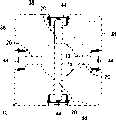
图1为本发明中定位夹持装置的实施例的正面剖面图。Fig. 1 is a front sectional view of an embodiment of a positioning and clamping device in the present invention.
图2为本发明中定位夹持装置的实施例的侧面剖面图。Fig. 2 is a side sectional view of an embodiment of the positioning and clamping device in the present invention.
图3为本发明中定位夹持装置的实施例的正面外观图,并显示了下部盖关闭的状态。Fig. 3 is a front appearance view of the embodiment of the positioning and clamping device in the present invention, and shows the state that the lower cover is closed.
图4为显为本发明中定位夹持装置的实施例的侧面外观图,并显示了下部盖关闭的状态。Fig. 4 is a side appearance view showing an embodiment of the positioning and clamping device of the present invention, and shows the closed state of the lower cover.
图5为沿图2中V-V线的剖面图。Fig. 5 is a sectional view along line V-V in Fig. 2 .
图6为沿图2中V-V线的剖面图,并仅显示了夹持主体。Fig. 6 is a cross-sectional view along line V-V in Fig. 2 and shows only the holding body.
图7为本发明中定位夹持装置的实施例的正面外观图,并显示了下部盖完全打开的状态。Fig. 7 is a front appearance view of an embodiment of the positioning and clamping device in the present invention, and shows a state in which the lower cover is fully opened.
图8为为本发明中定位夹持装置的实施例的侧面外观图,并显示了下部盖完全打开的状态。Fig. 8 is a side appearance view of an embodiment of the positioning and clamping device in the present invention, and shows a state in which the lower cover is fully opened.
图9A为本发明的定位夹持装置中防侵入装置的平面图。Fig. 9A is a plan view of the anti-intrusion device in the positioning and clamping device of the present invention.
图9B为防侵入装置的正面图。Fig. 9B is a front view of the anti-intrusion device.
图9C为防侵入装置的右侧视图。Figure 9C is a right side view of the anti-intrusion device.
图9D为防侵入装置的透视图。Figure 9D is a perspective view of the anti-intrusion device.
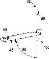
图10A为完全打开本发明中定位夹持装置的毛刺防护盖时的透视图。Fig. 10A is a perspective view when the burr protection cover of the positioning and clamping device of the present invention is fully opened.
图10B为以开度80度打开毛刺防护盖时的透视图。Fig. 10B is a perspective view when the burr protection cover is opened at an opening angle of 80 degrees.
图10C为完全打开毛刺防护盖时的侧视图。Figure 10C is a side view with the burr protection cover fully opened.
图10D为以开度80度打开毛刺防护盖时的侧视图。Fig. 10D is a side view when the burr protection cover is opened at an opening angle of 80 degrees.
图11A为关闭本发明中定位夹持装置的毛刺防护盖时的左侧视图。Fig. 11A is a left side view when the burr protection cover of the positioning and clamping device in the present invention is closed.
图11B为关闭毛刺防护盖时的平面图。Fig. 11B is a plan view with the burr protection cover closed.
图11C为关闭毛刺防护盖时的正面图。Fig. 11C is a front view with the burr protection cover closed.
图10D为关闭毛刺防护盖时的下视图。Figure 10D is a bottom view with the burr protection cover closed.
图11E为关闭刺防护盖时的透视图。Figure 1 IE is a perspective view with the puncture guard closed.
图11F为关闭毛刺防护盖时的右侧视图。Figure 1 IF is a right side view with the burr protection cover closed.
图12A为本发明中定位夹持装置的上部盖的左侧视图。Fig. 12A is a left side view of the upper cover of the positioning and clamping device in the present invention.
图12B为上部盖的平面图。Fig. 12B is a plan view of the upper cover.
图12C为上部盖的正面图。Fig. 12C is a front view of the upper cover.
图12D为上部盖的下视图。Figure 12D is a bottom view of the upper cover.
图12E为上部盖的透视图。Figure 12E is a perspective view of the upper cover.
图12F为上部盖的右侧视图。Figure 12F is a right side view of the upper cover.
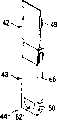
图13A为本发明中定位夹持装置的下部盖的左侧视图。Fig. 13A is a left side view of the lower cover of the positioning and clamping device in the present invention.
图13B为下部盖的平面图。Fig. 13B is a plan view of the lower cover.
图13C为下部盖的正面图。Fig. 13C is a front view of the lower cover.
图13D为下部盖的下视图。Figure 13D is a bottom view of the lower cover.
图13E为下部盖的透视图。Figure 13E is a perspective view of the lower cover.
图13F为下部盖的右侧视图。Figure 13F is a right side view of the lower cover.
图14A为以往的定位夹持装置的侧面外观视图。Fig. 14A is a side external view of a conventional positioning and clamping device.
图14B为图14A中主要部分的放大图。Fig. 14B is an enlarged view of the main part in Fig. 14A.
具体实施方式Detailed ways
图1~图13F显示了本发明的定位夹持装置。在图1~图13F中,与图14A,图14B的现有技术相同的部件采用了与图14A,图14B相同的标号。如图1~图8所示,夹持主体10由中空支柱状的主体29以及工件保持部件30构成,在夹持主体10上,以伸出状态形成定位销11。在主体29的上端中央部的空心处与工件保持部件30的下端中央部的空心处之间,夹持定位销11的基端部,主体29和工件保持部件30由图中未示出的螺栓等固定。在定位销11上形成下端开放的中空孔14,在中空孔14的侧部具有开口部22,通过开口部22连通中空孔14和外部。在图2中,开口部22形成于定位销11的左侧,通过穿过定位销11的基端部的通孔的图中未示出的定位销保证开口部22的位置。1 to 13F show the positioning and clamping device of the present invention. In FIGS. 1 to 13F, the same reference numerals as those in FIGS. 14A and 14B are used for components that are the same as those of the prior art in FIGS. 14A and 14B. As shown in FIGS. 1 to 8 , the
在保持部件30的上端形成环状底座面12,底座面12设置在定位销11的外侧。在夹持主体10的主体29的中央部形成垂直贯通的纵向孔13,并使纵向孔13与定位销11的中空孔14连通。使直动型致动器(汽缸)17与夹持主体10的下侧相连,直动型致动器(汽缸)17的输出部件(活塞杆)33在夹持主体10的纵向孔13内延伸。可自由移动地将夹持臂16设置在夹持主体10的纵向孔13以及定位销11的中空孔14内,通过连接销35,可相互自由转动地使夹持臂16的下端与输出部件33的上端部的两叉状连接部34相连。在夹持臂16的较宽部分中形成导向狭缝18,使支点销19穿过导向狭缝18,支点销19由夹持主体10的支点销支承孔20支承。An
伴随输出部件33的垂直运动,夹持臂16也垂直运动,并通过导向狭缝18和支点销19的卡合,夹持臂16的钩状顶端部23不仅垂直运动,而且还以连接销35为中心沿左右方向转动。在输出部件33向上方移动时,夹持臂16的顶端部23位于中空孔14内的上方的中央部,在输出部件33向下方移动时,夹持臂16的顶端部23向图2中的左侧转动,并朝开口部22的左侧伸出。在图2中显示了将定位销11插入板状工件24的定位孔36内,并且通过夹持臂16的顶端部23和底座面12夹持工件24的状态。Accompanied by the vertical movement of the
在夹持臂16的表面安装图9A~图9D中所示的防止毛刺侵入部件52,以防止毛刺等异物侵入夹持臂16的导向狭缝18内。在根据图1,图2以及图9A~图9D进行说明时,在防止毛刺侵入部件52中,通过连接板55、以保持规定间隔的方式连接第1防止板53和第2防止板54,在第1防止板53和第2防止板54上形成通孔56。使支点销19贯穿通孔56,第1防止板53和第2防止板54夹持大部分夹持臂16(除上部以外),连接销35位于第1防止板53和第2防止板54的切槽57A,57B内。另外,在图5中,省略了防止毛刺侵入的部件52的图示。A burr intrusion prevention member 52 shown in FIGS. 9A to 9D is mounted on the surface of the
如图5所示,夹持主体10的水平剖面为大致四边形,夹持主体10外侧的4个面形成安装面38。从中央的剖面为圆形的纵向孔13向安装面38的中央,形成4个支点销支承孔20。安装面38将定位夹持装置安装在主体焊接线的机架等的规定位置处,在安装面38上,如图3和4所示,形成多个安装螺纹孔46以及定位孔47,将轴颈销插入定位孔47内以进行定位,将螺栓拧入安装孔46内以将夹持主体10安装在规定装置中。As shown in FIG. 5 , the horizontal cross section of the holding
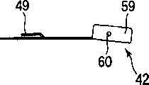
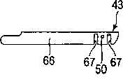
如图1,图2以及图6等所示,在夹持主体10的下方部形成使纵向孔13和4个安装面38的中央连通的毛刺排出孔25,纵向槽13可以通过毛刺排出孔25与外部连通。在夹持主体10的各个安装面38上,在支点销支承孔20的外侧端以及毛刺排出孔的排出端,形成纵向槽39,所述纵向槽从夹持主体10的上端向下端延伸,且剖面为长方形并且外端打开,使纵向槽与毛刺排出孔25以及支点销支承孔20相连通。纵向槽39两侧的侧壁40(在纵向槽39的3个壁中,在未开有毛刺排出孔25以及支点销支承孔20的壁)上分别形成滑动槽41,在两个滑动槽41上装有具有上部盖42和下部盖43的毛刺防护盖44(参见图10A~图10D)。As shown in Fig. 1, Fig. 2 and Fig. 6, etc., a
可相互转动地连接毛刺防护盖44的上部盖42和下部盖43,在上部盖42的两侧形成纵向延伸的弹性凸起49,同时,在下部盖43的两侧形成卡合凸起50。可以使上部盖42的弹性凸起49与两个滑动槽41结合,并使下部盖43的卡合凸起50与滑动槽41结合。通过毛刺防护盖44的上部盖42,防止支点销19的脱落,通过毛刺防护盖44的下部盖43打开和关闭毛刺排出孔25。另外,为了保持支承销19,可以仅使用上部盖42。The
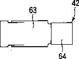
如图10A~13F所示,在上部盖42两侧部的上方附近的部分,在仅距两侧端规定距离的内侧部分形成具有规定长度的纵向切口,另外,在纵向切口的上端和两侧端之间的部分之间还形成了横向切口。另外,使纵向切口和两侧端之间的部分向内侧(图10C中的右侧)产生弹性变形,从而形成纵向延伸的弹性凸起49。使与上部盖42两侧的下端相距规定长度的部分向内侧弯曲,以形成相对于上部盖42的平面部64呈直角的弯曲部59,使两个弯曲部59之间的平面部64相对于不存在弯曲部59的部分的平面部63向外侧作一定程度的倾斜(参见图10C)。通过所述倾斜,上部盖42的平面部64和下部盖43的平面部65之间不存在间隙,从而防止了毛刺的侵入。两个弯曲部59之间的平面部64的宽度为大致从不存在弯曲部59的平面部63的宽度的两侧减去基本上板厚的长度所得的值。在两侧的弯曲部59的外侧面形成铰接孔60。As shown in FIGS. 10A to 13F, a longitudinal slit having a predetermined length is formed on the inner part of the upper part of the
下部盖43的两侧部分在整个长度范围内向内侧弯曲,并形成相对于下部盖43的平面部65呈直角的细长弯曲部66,细长弯曲部66的上端部比下部盖43的平面部65更向上方突出。在两个细长弯曲部66的突出部分的上端部内侧形成铰接用凸起61,下部盖43的平面部65的宽度与不存在上部盖42的弯曲部59的平面部63的宽度相同。另外,下部盖43的两细长弯曲部66的突出部分向顶端逐渐以很小的角度朝内侧弯曲。所述很小角度的变形会施加弹性力,从而在上部盖42的两个弯曲部59和下部盖43的两个细长弯曲部66之间产生保持力。通过所述保持力,可以将下部盖43保持在打开位置处,从而提高毛刺掏出操作的效率。在两个细长弯曲部66下方的外侧面上形成卡合凸起50,为了在两个卡合凸起50施加向外侧的弹性力,在两个卡合凸起50的垂直部分上形成切槽67。另外,在下部盖43的平面部65的下端部的表面上形成用于打开操作的凹槽(向里面的突出部)62。Both side portions of the
使下部盖43中两个弯曲部66的突出部分与上部盖42的两个弯曲部59的外侧重合,可自由转动地将两个弯曲部66的铰接用凸起61嵌入两个弯曲部59的铰接孔60内,如图10A~图10D所示,可以使下部盖43相对于上盖42转动。在定位夹持装置组装时,毛刺防护盖44的上部盖42左右的弹性凸起49以可自由滑动的状态与夹持主体10中纵向槽39的左右滑动槽41配合。虽然毛刺防护盖44由于弹性凸起49与滑动槽41配合而能够沿纵向滑动,但是,如图1~图4所示,使上部盖42的上端移动至与工件保持部件30的下表面接触的位置处,并将其保持在该位置处,因此,通过较小的外力并不能使其移动。另外,在下部盖43锁定时,使左右卡合凸起50与左右滑动槽41结合,将下部盖43保持在锁定位置处。并且,通过毛刺防护盖44的上部盖42以及下部盖43封闭纵向槽39,通过毛刺排出孔25以及支点销20,防止毛刺侵入夹持主体10的纵向孔13内。Make the protruding parts of the two
在打开下部盖43时,将小起子等的顶端钩挂在下部盖43的凹槽62的上端部上,在下部盖43上作用朝向打开方向的力。通过所述力,解除卡合凸起50与滑动槽41之间的卡合,使下部盖43以铰接用突起61为中心转动,从而能够打开下部盖43。在图10A~图10D中,显示了下部盖43以80度和135度(完全打开)打开的情况,在图7,图8中显示了完全打开下部盖43的状态。在图7,图8的状态下,将掏出用具插入毛刺排出孔25内,以便排出存积在纵向孔13内的毛刺。When opening the
Claims (4)
Translated fromChineseApplications Claiming Priority (3)
| Application Number | Priority Date | Filing Date | Title |
|---|---|---|---|
| JP189493/03 | 2003-07-01 | ||
| JP2003189493AJP3941059B2 (en) | 2003-07-01 | 2003-07-01 | Locate clamp device |
| JP189493/2003 | 2003-07-01 |
Publications (2)
| Publication Number | Publication Date |
|---|---|
| CN1576143Atrue CN1576143A (en) | 2005-02-09 |
| CN100358772C CN100358772C (en) | 2008-01-02 |
Family
ID=34074314
Family Applications (1)
| Application Number | Title | Priority Date | Filing Date |
|---|---|---|---|
| CNB200410062933XAExpired - Fee RelatedCN100358772C (en) | 2003-07-01 | 2004-07-01 | Positioning and clamping device |
Country Status (5)
| Country | Link |
|---|---|
| US (1) | US7188832B2 (en) |
| JP (1) | JP3941059B2 (en) |
| KR (1) | KR100543068B1 (en) |
| CN (1) | CN100358772C (en) |
| TW (1) | TWI263555B (en) |
Cited By (6)
| Publication number | Priority date | Publication date | Assignee | Title |
|---|---|---|---|---|
| CN102175144A (en)* | 2011-03-12 | 2011-09-07 | 石家庄市公安局刑事科学技术研究所 | Omnibearing bolt trace testing special bench |
| CN102114602B (en)* | 2010-01-06 | 2012-09-05 | 重庆振华制动器有限公司 | Fixture for machining brake cover of motorcycle copper/steel fiber non-asbestos drum brake |
| CN103930341A (en)* | 2011-08-29 | 2014-07-16 | 柯马(上海)工程有限公司 | Body assembly locking device and method |
| CN104507787A (en)* | 2012-08-20 | 2015-04-08 | 海克斯康测量技术有限公司 | Mechanical positioning device and method |
| CN107186651A (en)* | 2017-07-25 | 2017-09-22 | 江铃汽车股份有限公司 | Use the positioning compression mechanism in cubing |
| CN109514256A (en)* | 2018-12-28 | 2019-03-26 | 苏州凌稳智能装备有限公司 | The automatic assembly equipment of safety-type needle assemblies |
Families Citing this family (21)
| Publication number | Priority date | Publication date | Assignee | Title |
|---|---|---|---|---|
| JP3941059B2 (en)* | 2003-07-01 | 2007-07-04 | Smc株式会社 | Locate clamp device |
| US7815176B2 (en) | 2003-09-11 | 2010-10-19 | Phd, Inc. | Lock mechanism for pin clamp assembly |
| US7182326B2 (en)* | 2004-04-02 | 2007-02-27 | Phd, Inc. | Pin clamp |
| US7516948B2 (en)* | 2004-04-02 | 2009-04-14 | Phd, Inc. | Pin clamp accessories |
| US7448607B2 (en)* | 2004-12-15 | 2008-11-11 | Phd, Inc. | Pin clamp assembly |
| US20070267795A1 (en)* | 2006-02-06 | 2007-11-22 | Parag Patwardhan | Pin clamp transfer assembly and method of transferring a workpiece |
| DE102007022009B4 (en)* | 2007-05-08 | 2009-03-19 | Schenck Rotec Gmbh | Receiving device for balancing double clutches |
| ES2707249T3 (en) | 2007-06-19 | 2019-04-03 | Phd Inc | Pin clamp set |
| SG174814A1 (en)* | 2007-09-21 | 2011-10-28 | Memc Electronic Materials | Processes for purification of silicon tetrafluoride |
| US8376336B2 (en) | 2008-06-18 | 2013-02-19 | Phd, Inc. | Strip off pin clamp |
| US8459626B2 (en)* | 2010-05-28 | 2013-06-11 | Btm Corporation | Pin clamp |
| DE102010044327A1 (en)* | 2010-09-03 | 2012-03-08 | De-Sta-Co Europe Gmbh | Zentrierspannvorrichtung |
| US10052744B2 (en)* | 2011-01-10 | 2018-08-21 | GM Global Technology Operations LLC | Fixture for supporting a workpiece |
| CN102950552A (en)* | 2011-08-25 | 2013-03-06 | 富泰华工业(深圳)有限公司 | Positioning device |
| US9156510B2 (en) | 2012-10-17 | 2015-10-13 | Btm Company Llc | Clamp mounting system |
| JP6126951B2 (en)* | 2013-09-04 | 2017-05-10 | 武蔵精密工業株式会社 | Work positioning device |
| US9770810B2 (en)* | 2014-11-12 | 2017-09-26 | De-Sta-Co Europe Gmbh | Pin clamp |
| JP6688644B2 (en)* | 2016-03-02 | 2020-04-28 | 株式会社コスメック | Clamp device with lift function |
| US20180015580A1 (en)* | 2016-07-15 | 2018-01-18 | Tech Rim Standards, LLC | Adjustable pin clamping device |
| JP6751914B2 (en) | 2017-11-14 | 2020-09-09 | Smc株式会社 | Clamping device |
| KR102566000B1 (en)* | 2018-12-10 | 2023-08-10 | 가부시키가이샤 코스멕 | clamp device |
Family Cites Families (8)
| Publication number | Priority date | Publication date | Assignee | Title |
|---|---|---|---|---|
| JP3462330B2 (en)* | 1996-01-19 | 2003-11-05 | 株式会社コガネイ | Positioning clamp device |
| JP3634190B2 (en)* | 1999-05-24 | 2005-03-30 | Smc株式会社 | Clamping device |
| US6378855B1 (en)* | 1999-10-26 | 2002-04-30 | Btm Corporation | Locking pin clamp |
| MXPA01012811A (en)* | 2001-01-18 | 2002-11-04 | Progressive Tool & Ind Co | Clamping locator. |
| JP2002337770A (en) | 2001-05-21 | 2002-11-27 | Taiyo Ltd | Locating device |
| US6786478B2 (en)* | 2002-07-10 | 2004-09-07 | Welker Bearing Company | Locating assembly having an extendable clamping finger |
| JP3941059B2 (en)* | 2003-07-01 | 2007-07-04 | Smc株式会社 | Locate clamp device |
| US6902159B2 (en)* | 2003-08-21 | 2005-06-07 | Btm Corporation | Sealed pin locating and clamping apparatus |
- 2003
- 2003-07-01JPJP2003189493Apatent/JP3941059B2/ennot_activeExpired - Fee Related
- 2004
- 2004-06-10USUS10/865,716patent/US7188832B2/ennot_activeExpired - Lifetime
- 2004-06-16TWTW093117272Apatent/TWI263555B/ennot_activeIP Right Cessation
- 2004-06-30KRKR1020040050307Apatent/KR100543068B1/ennot_activeExpired - Lifetime
- 2004-07-01CNCNB200410062933XApatent/CN100358772C/ennot_activeExpired - Fee Related
Cited By (10)
| Publication number | Priority date | Publication date | Assignee | Title |
|---|---|---|---|---|
| CN102114602B (en)* | 2010-01-06 | 2012-09-05 | 重庆振华制动器有限公司 | Fixture for machining brake cover of motorcycle copper/steel fiber non-asbestos drum brake |
| CN102175144A (en)* | 2011-03-12 | 2011-09-07 | 石家庄市公安局刑事科学技术研究所 | Omnibearing bolt trace testing special bench |
| CN103930341A (en)* | 2011-08-29 | 2014-07-16 | 柯马(上海)工程有限公司 | Body assembly locking device and method |
| CN103930341B (en)* | 2011-08-29 | 2016-09-14 | 柯马(上海)工程有限公司 | Auto-body assembly locking device and method |
| CN104507787A (en)* | 2012-08-20 | 2015-04-08 | 海克斯康测量技术有限公司 | Mechanical positioning device and method |
| CN104507787B (en)* | 2012-08-20 | 2016-08-17 | 海克斯康测量技术有限公司 | Mechanical positioner and method |
| US10007250B2 (en) | 2012-08-20 | 2018-06-26 | Hexagon Metrology S.P.A. | Mechanical positioning device and method |
| CN107186651A (en)* | 2017-07-25 | 2017-09-22 | 江铃汽车股份有限公司 | Use the positioning compression mechanism in cubing |
| CN109514256A (en)* | 2018-12-28 | 2019-03-26 | 苏州凌稳智能装备有限公司 | The automatic assembly equipment of safety-type needle assemblies |
| CN109514256B (en)* | 2018-12-28 | 2024-01-26 | 苏州凌稳智能装备有限公司 | Automatic assembling equipment for safety needle assembly |
Also Published As
| Publication number | Publication date |
|---|---|
| US7188832B2 (en) | 2007-03-13 |
| KR100543068B1 (en) | 2006-01-20 |
| JP3941059B2 (en) | 2007-07-04 |
| JP2005021935A (en) | 2005-01-27 |
| TW200505625A (en) | 2005-02-16 |
| TWI263555B (en) | 2006-10-11 |
| KR20050004041A (en) | 2005-01-12 |
| US20050017423A1 (en) | 2005-01-27 |
| CN100358772C (en) | 2008-01-02 |
Similar Documents
| Publication | Publication Date | Title |
|---|---|---|
| CN1576143A (en) | Locating and clamping apparatus | |
| CN1108127C (en) | Fastener | |
| CN1912403A (en) | Arrangement for preventing axial movement of a bolt provided with a groove | |
| CN1083748C (en) | Vise assembly for cutting machine and fabrication method thereof | |
| CN1323868C (en) | Bumper mounting structure | |
| CN1497188A (en) | Elastic claw type connecting device | |
| CN1974094A (en) | A modular guard system and apparatus for a power saw | |
| US10640997B2 (en) | Motorized floor stripper machine | |
| EP3552771B1 (en) | Tool insert and/or tool holder insert, tool insert and/or tool holder insert system and tool and/or tool holder storage system | |
| CN1943943A (en) | Saw | |
| JP3999259B2 (en) | Shock absorber disassembly tool | |
| CN1902117A (en) | Car fall-prevention apparatus | |
| CN1469790A (en) | Fixing device for a jigsaw blade | |
| DE102014016012B4 (en) | Cutter | |
| CN1204346C (en) | Rodless cylinder | |
| RU2655252C2 (en) | Motor vehicle lock | |
| HK1049036A1 (en) | A roller for sliding door | |
| CN1867420A (en) | Apparatus and method for damping vibration in a machine tool | |
| CN1613601A (en) | Clamping device | |
| JP7089245B1 (en) | Dual gate valve | |
| CN1881461A (en) | Guide rail mounting clamp for hard disk drive | |
| EP2105233B1 (en) | Hand machine tool with attachment device | |
| CN218112484U (en) | Tail lamp cover assembly, supporting leg assembly and engineering machinery | |
| JP2009090299A (en) | Cam structure of press die | |
| CN215432611U (en) | Auxiliary supporting device |
Legal Events
| Date | Code | Title | Description |
|---|---|---|---|
| C06 | Publication | ||
| PB01 | Publication | ||
| C10 | Entry into substantive examination | ||
| SE01 | Entry into force of request for substantive examination | ||
| C14 | Grant of patent or utility model | ||
| GR01 | Patent grant | ||
| CF01 | Termination of patent right due to non-payment of annual fee | Granted publication date:20080102 Termination date:20200701 | |
| CF01 | Termination of patent right due to non-payment of annual fee |