CN1568407A - An improved continuously variable transmission device - Google Patents
An improved continuously variable transmission deviceDownload PDFInfo
- Publication number
- CN1568407A CN1568407ACNA028199472ACN02819947ACN1568407ACN 1568407 ACN1568407 ACN 1568407ACN A028199472 ACNA028199472 ACN A028199472ACN 02819947 ACN02819947 ACN 02819947ACN 1568407 ACN1568407 ACN 1568407A
- Authority
- CN
- China
- Prior art keywords
- continuously variable
- variable transmission
- planetary
- race
- parts
- Prior art date
- Legal status (The legal status is an assumption and is not a legal conclusion. Google has not performed a legal analysis and makes no representation as to the accuracy of the status listed.)
- Granted
Links
Images


Classifications
- F—MECHANICAL ENGINEERING; LIGHTING; HEATING; WEAPONS; BLASTING
- F16—ENGINEERING ELEMENTS AND UNITS; GENERAL MEASURES FOR PRODUCING AND MAINTAINING EFFECTIVE FUNCTIONING OF MACHINES OR INSTALLATIONS; THERMAL INSULATION IN GENERAL
- F16H—GEARING
- F16H15/00—Gearings for conveying rotary motion with variable gear ratio, or for reversing rotary motion, by friction between rotary members
- F16H15/48—Gearings for conveying rotary motion with variable gear ratio, or for reversing rotary motion, by friction between rotary members with members having orbital motion
- F16H15/50—Gearings providing a continuous range of gear ratios
- F16H15/503—Gearings providing a continuous range of gear ratios in which two members co-operate by means of balls or rollers of uniform effective diameter, not mounted on shafts
- F—MECHANICAL ENGINEERING; LIGHTING; HEATING; WEAPONS; BLASTING
- F16—ENGINEERING ELEMENTS AND UNITS; GENERAL MEASURES FOR PRODUCING AND MAINTAINING EFFECTIVE FUNCTIONING OF MACHINES OR INSTALLATIONS; THERMAL INSULATION IN GENERAL
- F16H—GEARING
- F16H15/00—Gearings for conveying rotary motion with variable gear ratio, or for reversing rotary motion, by friction between rotary members
- F16H15/48—Gearings for conveying rotary motion with variable gear ratio, or for reversing rotary motion, by friction between rotary members with members having orbital motion
- F16H15/50—Gearings providing a continuous range of gear ratios
- F16H15/506—Gearings providing a continuous range of gear ratios in which two members of non-uniform effective diameter directly co-operate with one another
- F—MECHANICAL ENGINEERING; LIGHTING; HEATING; WEAPONS; BLASTING
- F16—ENGINEERING ELEMENTS AND UNITS; GENERAL MEASURES FOR PRODUCING AND MAINTAINING EFFECTIVE FUNCTIONING OF MACHINES OR INSTALLATIONS; THERMAL INSULATION IN GENERAL
- F16H—GEARING
- F16H61/00—Control functions within control units of change-speed- or reversing-gearings for conveying rotary motion ; Control of exclusively fluid gearing, friction gearing, gearings with endless flexible members or other particular types of gearing
- F16H61/38—Control of exclusively fluid gearing
- F16H61/40—Control of exclusively fluid gearing hydrostatic
- F16H61/4165—Control of cooling or lubricating
- F—MECHANICAL ENGINEERING; LIGHTING; HEATING; WEAPONS; BLASTING
- F16—ENGINEERING ELEMENTS AND UNITS; GENERAL MEASURES FOR PRODUCING AND MAINTAINING EFFECTIVE FUNCTIONING OF MACHINES OR INSTALLATIONS; THERMAL INSULATION IN GENERAL
- F16H—GEARING
- F16H57/00—General details of gearing
- F16H57/04—Features relating to lubrication or cooling or heating
- F16H57/048—Type of gearings to be lubricated, cooled or heated
- F16H57/0487—Friction gearings
- F16H57/049—Friction gearings of the toroid type
- F—MECHANICAL ENGINEERING; LIGHTING; HEATING; WEAPONS; BLASTING
- F16—ENGINEERING ELEMENTS AND UNITS; GENERAL MEASURES FOR PRODUCING AND MAINTAINING EFFECTIVE FUNCTIONING OF MACHINES OR INSTALLATIONS; THERMAL INSULATION IN GENERAL
- F16H—GEARING
- F16H61/00—Control functions within control units of change-speed- or reversing-gearings for conveying rotary motion ; Control of exclusively fluid gearing, friction gearing, gearings with endless flexible members or other particular types of gearing
- F16H61/66—Control functions within control units of change-speed- or reversing-gearings for conveying rotary motion ; Control of exclusively fluid gearing, friction gearing, gearings with endless flexible members or other particular types of gearing specially adapted for continuously variable gearings
- F16H61/664—Friction gearings
Landscapes
- Engineering & Computer Science (AREA)
- General Engineering & Computer Science (AREA)
- Mechanical Engineering (AREA)
- Friction Gearing (AREA)
- Transmission Devices (AREA)
- Valve Device For Special Equipments (AREA)
- Valve-Gear Or Valve Arrangements (AREA)
- Transplanting Machines (AREA)
- General Details Of Gearings (AREA)
- Vehicle Body Suspensions (AREA)
- Transmitters (AREA)
- Radio Transmission System (AREA)
- Reduction Or Emphasis Of Bandwidth Of Signals (AREA)
- Transmissions By Endless Flexible Members (AREA)
Abstract
Description
Translated fromChinese技术领域technical field
本发明涉及一种改进的无级变速传动装置。The present invention relates to an improved continuously variable transmission.
背景技术Background technique
具体而言,本发明涉及这样一种无级变速传动装置:其具有一些行星构件和控制装置,其中的行星构件与位于径向内侧和径向外侧的座圈保持滚动接触,径向内侧座圈和外侧座圈都包括两个在轴向上分离开的部件,控制装置则用于选择性地改变其中一座圈的两部件之间的轴向间距,因而可改变与此滚动接触的行星构件的位置。这种传动装置可具有这样的部件:其对施加于该变速器的两驱动传递构件(即输入轴和输出轴)之一上的扭矩敏感,以确定出另一座圈的两部件之间间距的变动补偿量,进而确定出该装置的传动比;还可以由此来改变行星构件与座圈之间相互传递的、且与二者之间接触面垂直的作用力。利用一层非常薄的润滑剂膜来对行星构件与座圈之间的滚动接触进行润滑。该润滑剂薄膜的存在是非常重要的,这样才可以防止相对运动的构件之间发生干摩擦,干摩擦会导致变速器出现早期磨损;但该薄膜也应当是很薄的,以防止行星构件与座圈之间发生滑动。More specifically, the present invention relates to a continuously variable transmission having planetary members in rolling contact with radially inner and radially outer races, the radially inner race Both the outer and outer races consist of two axially separated parts, and the control device is used to selectively change the axial distance between the two parts of one of the races, thereby changing the rolling contact with the planetary member. Location. Such transmissions may have components that are sensitive to torque applied to one of the transmission's two drive transmitting members (i.e. input and output shafts) to determine variations in the spacing between the two components of the other race The compensation amount determines the transmission ratio of the device; it can also change the force transmitted between the planetary member and the seat ring and perpendicular to the contact surface between the two. The rolling contact between the planetary members and the races is lubricated with a very thin film of lubricant. The presence of this lubricant film is very important to prevent dry friction between relatively moving components, which can lead to early wear of the transmission; but the film should also be very thin to prevent the planetary components from contacting the seat Slippage occurs between circles.
在设计中,一个非常重要的原则是:传动装置应当在最常用的传动比上具有最高的效率,最常用的传动比是指使用时间最长的那个传动比。所有的传动装置都会由于摩擦而损失一定的功率、进而发热,在设计上,通常要使所谓的“顶级”传动比具有最高的效率,其中的“顶级”传动比是这样一个传动比:在该传动比上,当输入轴为给定转速时,输出轴的转速最大。在普通的阶进式(incremental ratio)齿轮箱中,通常是在输出轴与输入轴具有相同转速—即传动比为1∶1或“直接”传动比时,传动效率最高。但是,在某些情况下,效率最高的传动比可能小于1∶1,与此对照,有时还希望传动比能大于1∶1。In the design, a very important principle is: the transmission should have the highest efficiency in the most commonly used transmission ratio, which means the transmission ratio that has been used for the longest time. All transmissions lose a certain amount of power due to friction and generate heat, and are usually designed for maximum efficiency in what is called a "top" gear ratio, where a "top" gear ratio is one that: In terms of transmission ratio, when the input shaft is at a given speed, the output shaft rotates at a maximum speed. In an ordinary incremental ratio gearbox, the transmission efficiency is usually highest when the output shaft and the input shaft have the same speed—that is, a transmission ratio of 1:1 or a "direct" transmission ratio. However, in some cases, the most efficient transmission ratio may be less than 1:1, in contrast to this, it is sometimes desirable to have a transmission ratio greater than 1:1.
在上述类型的滚动接触型无级变速传动装置中,动力可以是从径向内侧的座圈输入到装置中的,且装置的动力是经行星从动件或行星架从行星构件输出的,而其中的外座圈则构成了固定不同的部件。当径向外侧座圈的两部件处于最大间距位置、而内侧座圈的两部件却尽可能地相互靠近时,实际上将行星构件“推挤”向其径向最远的位置处,此时能达到很大的传动比。当然,可以理解:输入轴和输出轴是可互换的,而且,在所讨论的结构设计中,三个主要部件一即径向内侧座圈、行星组件、以及径向外侧座圈的作用都是可互换的,因而,可将它们中的之一保持固定不动,而将另外的两个用作输入轴或输出轴,其中的行星组件包括行星从动件和行星架。但是,目前已经发现:从结构装配的角度考虑,上文中用外座圈作为固定件的结构是尤其有利的。In the rolling contact type continuously variable transmission of the above type, the power may be input into the device from the radially inner race, and the power of the device is output from the planetary member through the planetary follower or the planetary carrier, and The outer race among them constitutes the fixed different parts. When the two parts of the radially outer race are at the maximum spacing position, while the two parts of the inner race are as close as possible to each other, the planetary members are actually "pushed" to their radially furthest positions, at which point A large transmission ratio can be achieved. Of course, it is understood that the input and output shafts are interchangeable and that, in the design in question, the roles of the three main components—the radially inner race, the planetary assembly, and the radially outer race—are all are interchangeable so that one of them can be kept stationary while the other two are used as input or output shafts, where the planetary assembly includes the planetary follower and the planetary carrier. However, it has now been found that the above configuration with the outer race as the fixing member is particularly advantageous from a structural assembly point of view.
但是,如果行星构件是滚球,则此构造传动装置就会暴露出一个缺陷:为了达到可能的最大传动比,行星构件与座圈之间发生滚动接触的部位要靠近于它们行程范围的末端位置(在径向内侧座圈的情况下,该位置最为靠近滚球的轴线,而在径向外侧座圈的情况下,该位置距离滚球的轴线最远)。在末端行程位置处,在行星构件与两座圈之一的接触部位,行星构件在座圈上的滚动会产生显著的“自旋”量。However, if the planetary members are rolling balls, this construction of the transmission reveals a drawback: in order to achieve the maximum possible transmission ratio, the rolling contact between the planetary members and the raceways is located close to the end positions of their travel ranges (In the case of a radially inner race, this position is closest to the axis of the ball, and in the case of a radially outer race, this position is farthest from the axis of the ball). At the end of travel position, the rolling of the planet member on the race produces a significant amount of "spin" at the point where the planet member contacts one of the races.
发明内容Contents of the invention
本发明涉及一种属于上述类型的、滚动接触型无级变速传动装置,在该传动装置中,装置在高传动比时过度发热的缺陷被减轻,且能使高传动比时接触部位自旋量与滚转角速度的比值达到一个更为有利的数值。The present invention relates to a rolling contact type continuously variable transmission of the above-mentioned type, in which the defect of excessive heat generation of the device at high transmission ratios is alleviated, and the amount of spin of the contact parts at high transmission ratios can be reduced. The ratio to the roll angular velocity reaches a more favorable value.
根据本发明,上述的目的是通过将行星构件的形状从基本为球形构造变化为椭球体(或者为长球体、或者为扁球体)形状来实现的,实质上,这样的设计将使得接触部位在发生位置变化时能保持一个更为有利的接触角。According to the invention, the aforementioned objects are achieved by changing the shape of the planetary members from a substantially spherical configuration to an ellipsoidal (either prolate spheroidal or oblate spheroidal) shape, such that in essence such a design will result in a contact point at A more favorable contact angle can be maintained when position changes occur.
本发明还包括这样的方案:借助于固定的连杆—而非借助于行星从动件将行星构件直接连接到行星架上,在早期的结构设计中,由行星从动件自身将作用在行星构件上的力传递给行星架,然后再传递给输出轴、或从输入轴输出。The invention also includes the solution of connecting the planet members directly to the planet carrier by means of fixed connecting rods—rather than by means of planetary followers, which, in earlier structural designs, would act on the planetary members themselves. The force on the member is transmitted to the planet carrier, which is then transmitted to the output shaft, or output from the input shaft.
因而,根据本发明的一个方面,对一种无级变速传动装置进行了设置,该传动装置具有与径向内侧座圈和外侧座圈滚动接触的行星构件,外侧、内侧座圈都包括可在轴向上相对运动、从而分离开的部件,该传动装置还包括用于确定两座圈中某一座圈两部件之间轴向间隔的控制装置,对该传动装置的设置使得行星构件通过一连杆与行星架连接起来、以便于实现行星运动,连杆使行星构件的径向位置可响应于所述座圈中两部件之间轴向间隔的变化而变动,同时还能保持周向的连接关系。Thus, according to one aspect of the invention, a continuously variable transmission is provided having planetary members in rolling contact with a radially inner race and an outer race, both including Parts that move relative to each other in the axial direction and thus separate. The transmission device also includes a control device for determining the axial distance between the two parts of a certain seat ring in the two races. The transmission device is set so that the planetary member passes through a continuous Rods are connected to the planet carrier to facilitate planetary motion, and linkages allow the radial position of the planetary members to vary in response to changes in the axial spacing between the two parts in the race, while maintaining a circumferential connection relation.
该连杆可被制成“后拖杆”的构造,在此结构设计中,通过在行星构件上设置一中央通道、并将连杆伸入到该通道中,将行星架在行星构件的轴向中点位置处接合到行星构件上。因而,对力的传递是对称平衡的,并能获得很多其它的优点,下文对此有更为详细的介绍。The connecting rod can be made into a "rear drag bar" structure. In this structural design, the planetary carrier is placed on the axis of the planetary member by providing a central channel on the planetary member and extending the connecting rod into the channel. Engages to the planet member at the midpoint. Thus, the transmission of forces is symmetrically balanced and a number of other advantages are obtained, which will be described in more detail below.
在实际应用中,可将本发明的传动装置设计成这样:行星构件为组合体的形式,其包括两个滚子元件,每一滚子元件都具有一个用于与两座圈的对应部件相接合的外回旋表面。可利用一母线来形成该旋转表面,该母线例如是直线,或者包括直线部分、凸曲线部分或凹曲线部分。当然,座圈的形状必须与行星构件的形状相对应(但非相配),在行星构件表面为直线形状或凹面形状的情况下,座圈应凸向行星构件,在行星构件表面为凸面形状时,座圈的形状应当是内凹的,后者的情况被认为是最为便利的结构。In practical application, the transmission device of the present invention can be designed in such a way that the planetary member is in the form of a combined body, which includes two roller elements, and each roller element has a Jointed outer convolution surface. The surface of revolution may be formed by a generatrix, for example straight, or comprising straight, convex or concave curves. Of course, the shape of the seat ring must correspond to (but not match) the shape of the planetary member. In the case of a linear shape or a concave shape on the surface of the planetary member, the seat ring should be convex to the planetary member. When the surface of the planetary member is convex in shape , the shape of the seat ring should be concave, and the latter case is considered to be the most convenient structure.
如上所讨论的那样,可在行星构件的赤道部位设置一通道,连杆延伸到该通道中,在采用组合行星构件的情况下,组成该构件的两个单独的滚子元件被一中间元件结合起来,所述连杆被连接到该中间元件上。As discussed above, a channel may be provided at the equator of the planetary member into which the connecting rod extends, and in the case of a combined planetary member, the two separate roller elements that make up the member are joined by an intermediate member Up, the connecting rod is connected to the intermediate element.
每一行星构件体的中间元件都可通过滚珠轴承—优选为滚针轴承结合到所述连杆上,其部分地位于滚子元件内。为此目的,可将每个滚子元件的形状设计成半贝壳状。各个行星构件体与行星架之间连杆的形式可以是与各个行星构件相对应的后拖臂。当然,此处所用的词语“后拖”是与仅在一个方向上的相对运动相关。在相对运动的另一方向上,“后拖”臂就会变为“前导”臂。对于这样的结构设计,由于位于后拖臂端部的行星构件、以及与行星架相连的连杆都被约束成只能产生圆周运动,所以可令人满意地对作用力进行传递。The intermediate element of each planetary member body may be coupled to the connecting rod by means of ball bearings, preferably needle bearings, which are partly located within the roller elements. For this purpose, each roller element can be designed in the shape of a half-shell. The form of the connecting rod between each planet member body and the planet carrier may be a rear trailing arm corresponding to each planet member. Of course, the term "drag" as used herein relates to relative movement in only one direction. In the other direction of relative motion, the "trailing" arm becomes the "leading" arm. With such a structural design, since the planetary member located at the end of the rear trailing arm and the connecting rod connected to the planetary carrier are constrained to produce only circular motion, the force can be transmitted satisfactorily.
通常,每一行星构件体中每一滚子元件的回旋表面都是由一弧曲母线限定而成的。该母线无须是圆的一部分,事实上,其无须是对称的、或者甚至无须是正则曲线。但是,在本发明的一实施方式中,每一滚子元件表面的弧曲母线都是一段圆弧,且优选地是:限定每一滚子元件表面母线的圆弧的圆心在轴向和/或径向上偏离行星构件的中点。如果将球形的行星构件作为标准或示例性的形状,则实际上通过将该基础表面沿径向向内移向中心位置、以形成一伪球体,就可使本发明所用的行星构件实现该优选形状。可按照两种方式来实现此方案。如果从一假想的球体开始进行设计,则可从该整体球上去掉一赤道面“切片”,并将剩下的两个部分贴合到一起,这样做的效果类似于形成一个扁球体。类似地,如果从球体中去掉一个圆柱部分,且该圆柱部分环绕着行星元件的转动轴线,并从球体的一极延伸到另一极,而后,在实际上对球体的剩余部分进行压缩(同时保持相同的形状)、以替代被去掉的材料,这样做的效果将使行星构件体的表面趋于变为一个更长的球体。最终的结果是:由座圈接合着的滚动元件的表面包括球面上这样一些部分:它们靠近起始时假想球体的表面的中间区段或“中央部分”,这些表面部分靠近滚动轴线、以及被去掉或略去的赤道面区域。这将形成一个物体,在滚动方向上,其表面的曲率大于在横交方向上的曲率。然而,上文关于对假想球体进行处理的描述并非是为了介绍行星元件的制造过程,而仅是为了对最终形成的形状进行描述。对于组合式滚动元件,其两个轴向半分体是完全相同的,可将两半分体都制成“贝壳”状,并可如上文所述那样,利用一中间构件将两半分体开口相对地结合到一起。事实上,如果该表面是由圆弧形式的母线形成的,则限定每一滚子元件表面母线的圆弧的圆心在轴向和/或径向上偏离行星构件的中点。Typically, the surface of revolution of each roller element in each planet member body is defined by a curved generatrix. The generatrix need not be part of a circle, in fact, it need not be symmetrical, or even a regular curve. However, in one embodiment of the present invention, the curved generatrix of each roller element surface is a circular arc, and preferably: the center of the arc defining the generatrix of each roller element surface is in the axial direction and/or Or radially offset from the midpoint of the planetary member. If a spherical planet member is the standard or exemplary shape, the planet member used in the present invention can be made to achieve this preference by actually moving the base surface radially inward toward the center to form a pseudo-spheroid. shape. This scheme can be implemented in two ways. If you start your design with an imaginary sphere, you can remove an equatorial "slice" from the overall sphere and snap the remaining two parts together, which has the effect of forming an oblate spheroid. Similarly, if a cylindrical portion is removed from the sphere, and this cylindrical portion encircles the axis of rotation of the planetary element and extends from one pole of the sphere to the other, then, in effect, compresses the remaining portion of the sphere (while retain the same shape) to replace the removed material, the effect of which is to make the surface of the planetary member body tend to become a longer sphere. The end result is that the surface of the rolling element engaged by the raceway includes portions of the sphere that are near the middle section or "central portion" of the surface of the imaginary sphere at the start, which are near the rolling axis, and are The area of the equatorial plane that is removed or omitted. This results in an object whose surface has a greater curvature in the rolling direction than in the transverse direction. However, the above description of the treatment of the imaginary sphere is not intended to describe the manufacturing process of the planetary element, but only to describe the final formed shape. For combined rolling elements, the two axial half-splits are exactly the same, and both half-splits can be made into a "shell" shape, and as mentioned above, an intermediate member can be used to connect the openings of the two half-splits to each other. combine together. In fact, if the surface is formed by generatrixes in the form of circular arcs, the centers of the arcs defining the generatrixes of the surface of each roller element are offset axially and/or radially from the midpoint of the planetary members.
在本发明的一优选实施方式中,行星架具有多个支臂,它们基本上平行于传动装置转动轴线从其轴向端部延伸出,且所述支臂的自由端被一增强环所加强,增强环将所述支臂的所有自由端都连接到一起。该增强环占据了行星架上支臂端部与传动装置端盖之间的空间,并位于内侧座圈的径向外侧,从而不会干涉内侧座圈的运动。In a preferred embodiment of the invention, the planet carrier has a plurality of arms extending from its axial ends substantially parallel to the axis of rotation of the transmission, and the free ends of the arms are reinforced by a reinforcing ring , a reinforcing ring connects all the free ends of the arms together. The reinforcing ring occupies the space between the end of the upper arm of the planet carrier and the transmission end cover and is positioned radially outward of the inner race so as not to interfere with the movement of the inner race.
所述的径向内侧座圈与径向外侧座圈被设置在一个固定的壳体内,且所述两座圈中的之一可借助于该传动装置的输入轴或输出轴而相对于壳体转动。在本发明一优选实施方式中,径向内侧座圈可利用变速器的输入构件而相对于壳体转动。与此类似,优选地是,行星架可利用变速器的输出构件而相对于壳体转动。The radially inner race and the radially outer race are arranged in a fixed housing, and one of the two races can be moved relative to the housing by means of the input shaft or output shaft of the transmission. turn. In a preferred embodiment of the invention, the radially inner race is rotatable relative to the housing by means of an input member of the transmission. Similarly, it is preferred that the planet carrier is rotatable relative to the housing by means of the output member of the transmission.
在这样的结构中,可以使输入构件和输出构件(二者例如都可以是轴)都从壳体的同一侧突伸出,例如通过将输出轴制成空心轴、并将其同轴地套在输入轴上就可实现这样的设计。这样的结构尤其适用于作为两轮车辆的变速器,在两轮车辆中,驱动轮的驱动变速器采用链条驱动的形式。In such a construction, both the input member and the output member (both may be shafts, for example) can protrude from the same side of the housing, for example by making the output shaft hollow and fitting it coaxially. Such a design can be realized on the input shaft. Such a structure is particularly suitable as a transmission for a two-wheeled vehicle, in which the drive transmission for the drive wheels is in the form of a chain drive.
为了保证对本发明传动装置的润滑和冷却,设置了多条通道来引入润滑剂,润滑剂被泵送而流经装置的过程中,其还起到冷却剂的作用。为此目的,输入轴的一端—优选为与从壳体中突伸出的那一端相反的端部具有一通道,其用于将润滑剂沿轴向引入。优选地是,该润滑剂通道具有这样一个部分:其沿径向穿通输入轴而到达由所述径向内侧座圈部件所占据的区域处,更为优选地是,该部分通到两活动座圈部件之间的中间区域。In order to ensure lubrication and cooling of the transmission device of the present invention, multiple channels are provided to introduce lubricant, which also acts as a coolant when it is pumped through the device. For this purpose, one end of the input shaft, preferably the end opposite the end protruding from the housing, has a channel for introducing lubricant in the axial direction. Preferably, the lubricant channel has a portion which passes radially through the input shaft to the area occupied by said radially inner race member, more preferably, this portion leads to two movable seats The middle area between circle parts.
为了使两座圈部件能实现相对轴向移动,可利用螺旋联轴器来将二者互连起来,通过在两部件之间使用滚动元件,可减小相互之间的摩擦接合。在螺旋联轴器中应用该滚动元件所要遇到的一个困难在于:滚动元件存在向运动行程范围的某一末端或另一末端蠕滑的可能性。如果出现了这种情况,则位于行程末端的滚动元件就会接触到一个止挡,该止挡可防止滚动元件进一步滑动,但这会增大摩擦接触,当滚动元件抵触到末端部位时,由于止挡迫使其无滚动地转动,从而会降低滚动元件的效率。为了避免这一困难,本发明设计了这样一种结构:在滚动元件行列的每一端部都设置刚性的相互接合装置,以此来防止滚动元件与座圈部件在传动装置工作过程中发生相对滑动(蠕滑)。这种刚性的相互接合装置例如包括相互配合的齿牙组,这些齿牙分别位于滚动元件行列端部(一端或每个端部)处的滚动元件上、以及与之接触的座圈部件上。因而,由于齿牙之间的相互接合可防止出现任何的滑移,所以该端部元件在移位时将只能滚动。In order to enable the relative axial movement of the two race parts, a helical coupling can be used to interconnect the two, and the frictional engagement between the two parts can be reduced by using rolling elements between the two parts. One difficulty encountered with the use of such rolling elements in helical couplings is the potential for the rolling elements to creep toward one end or the other of the range of motion travel. If this happens, the rolling elements at the end of the stroke come into contact with a stop that prevents the rolling elements from sliding further, but this increases the frictional contact when the rolling elements hit the end position due to The stop forces it to turn without rolling, which reduces the efficiency of the rolling element. In order to avoid this difficulty, the present invention designs such a structure: a rigid mutual engagement device is provided at each end of the row of rolling elements, so as to prevent the relative sliding of the rolling elements and the raceway parts during the operation of the transmission (creep). Such rigid interengaging means comprise, for example, sets of cooperating teeth on the rolling elements at the ends (one or each end) of the row of rolling elements, respectively, and on the race part in contact therewith. Thus, the end element will only be able to roll when displaced, since the interengagement between the teeth prevents any slippage.
作为备选方案,滚动元件自身可具有特殊的构造。滚动元件可以并非是球形或圆柱形的元件,其表面为螺旋构造,以便于与两座圈部件上对应的螺旋表面构造相接合,其中,该滚动元件位于这两个座圈部件之间。事实上,两座圈部件具有相互配合的螺纹线,且滚动元件上具有对应的螺纹线,此螺纹线与两个可相对移动的座圈部件上的螺纹相接合,其中,每一滚动元件都在整个接触长度的范围内延伸。滚动元件在其沿某一部件的螺纹线滚动的同时发生轴向移位的任何趋势都被一个使其在相反方向上轴向移动的趋势所抵消,其中的后一趋势是借助于其沿自身螺纹线的滚动移位而产生的。As an alternative, the rolling elements themselves can have a special configuration. The rolling element may be a non-spherical or cylindrical element whose surface is helically configured to engage a corresponding helical surface configuration on the two race parts between which the rolling element is located. In fact, the two race parts have cooperating threads and the rolling elements have corresponding threads which engage threads on the two relatively movable race parts, wherein each rolling element has Extends over the entire contact length. Any tendency of a rolling element to displace axially while it is rolling along the thread line of a component is counteracted by a tendency to move it axially in the opposite direction by virtue of its Produced by the rolling displacement of the thread line.
许多种无级变速传动装置存在的一个局限性在于装置无法在两个方向上传递扭矩(区别于可双向驱动的变速器),换言之,尽管该装置可传递加速驱动,但却无法由发动机来实现减速驱动,减速驱动是指当从动构件或输出构件的速度快于主动构件或输入构件时负载所施加的驱动作用。这种情况对于驾驶汽车的人员来讲是很熟悉的,这种情形被称为超发动机转速的工况,此现象会对车辆施加发动机牵阻制动。但只能单向传递扭矩的变速器则无法提供这种超速功能,而该功能对于动力交通运输的场合是很重要的。本发明的变速器具有双向传递扭矩的功能。通过利用相同旋向的螺纹联轴器将所述另一座圈的部件与其所对应驱动构件(无论是输入构件还是输出构件)接合起来,则不论主动构件和从动构件是什么样的转动方向,由该传动装置执行扭矩传递(一方向或另一方向上)而使两座圈部件受到的顶推作用都是在同一方向上。通过在该组件的两端处设置一限位止挡来限制“前导”座圈部件的运动(在此语境中,可以理解:对于座圈部件相对于有关驱动构件或从动构件的任一运动方向,都始终存在一个位于前方的构件和一个落后的构件,如果相对运动方向逆反,则前导构件与后随构件的角色就会互换),因而,不论瞬时的传动比是多大,当扭矩的方向发生改变时,所述另一座圈的两个部件从它们所对应的驱动构件或从动构件的一端向一端一起移动,且螺纹联轴器保持着它们之间作用着的、并促使它们靠近的作用力。驱动构件或从动构件上靠近端部止挡的部位要比构件上的其余部位受到更大的应力(不论是扭转应力、还是拉伸引力),原因在于端部止挡只对轴向力产生反作用。为了提供大的传动比范围,就必须要使驱动构件或从动构件保持着很小的径向尺寸。但是,对于较高功率的应用场合(例如用作机动车的变速器),则需要采用较大的零件,以便于能承受施加在系统上的大负载。为此原因,考虑将本发明的实施方式设计成这样:在端部止挡上制有不但能对轴向力产生反作用、而且能抵抗扭矩的措施。这一设计方案例如可通过将端部止挡制成爪式离合器止挡的形式。理论上讲,一个仅对扭矩产生反作用、但不抵抗轴向力的90°的爪齿将是可行的,但由于座圈上配对爪齿必须要接近一个由滚珠螺旋丝杠确定的小角度,所以该爪齿的支承面积将是非常小的。最佳的方案是采用在典型爪齿的90°齿角与单纯止挡的0°“齿”角之间的某个角度,此处,在支承面积、轴应力、以及滚珠丝杠的负载方面,选用25°的角度能使各方面的性能达到最好。A limitation of many types of continuously variable transmissions is that the device cannot transmit torque in both directions (as opposed to a transmission that can be driven both ways), in other words, although the device can transmit acceleration drive, it cannot be decelerated by the engine Drive, Reduction drive is the driving action exerted by a load when the speed of the driven or output member is faster than that of the driving or input member. This situation is familiar to motorists and is known as an over-rev condition, which applies engine drag braking to the vehicle. But a transmission that can only transmit torque in one direction cannot provide the overspeeding capability that is important in power transportation applications. The speed changer of the present invention has the function of bidirectionally transmitting torque. By engaging the part of said other race with its corresponding drive member (whether input or output) by means of a threaded coupling of the same hand direction, regardless of the direction of rotation of the driving and driven members, Torque transmission (in one direction or the other) is performed by the transmission such that both race members are subjected to thrust in the same direction. The movement of the "leading" race part is limited by providing a limit stop at both ends of the assembly (in this context, it is understood that for any In the direction of motion, there is always a member in front and a member behind, if the relative direction of motion is reversed, the roles of the leading member and the following member will be exchanged), so no matter what the instantaneous transmission ratio is, when the torque When the direction of the other race changes, the two parts of the other race move together from one end to the other of their corresponding drive member or driven member, and the threaded coupling maintains the force acting between them and urges them proximity force. The part of the driving member or the driven member near the end stop is subjected to greater stress (whether it is torsional stress or tensile attraction) than the rest of the member because the end stop only acts on the axial force. reaction. In order to provide a wide range of gear ratios, it is necessary to keep the radial dimensions of the drive or driven member small. However, for higher power applications (eg, as a transmission in a motor vehicle), larger components are required in order to be able to withstand the large loads placed on the system. For this reason, it is conceivable to design an embodiment of the invention in such a way that not only counteracting axial forces but also torque-resistant measures are formed on the end stop. This refinement is possible, for example, by making the end stop in the form of a jaw clutch stop. Theoretically, a 90° prong that reacts only to torque, but not axial force, would be feasible, but since the mating prongs on the race must approach a small angle determined by the ball screw, So the bearing area of the prongs will be very small. The optimal solution is to use an angle somewhere between the 90° tooth angle of a typical prong and the 0° "tooth" angle of a simple stop, here, in terms of bearing area, shaft stress, and load on the ball screw , Selecting an angle of 25° can achieve the best performance in all aspects.
接触角为25°的爪式驱动件可被看作是与第一接合机构(滚珠丝杠)平行、但位于相反侧的第二螺旋接合机构,从而,有利地是:载荷将由两接合机构共同分担。A jaw drive with a contact angle of 25° can be seen as a second helical engagement mechanism parallel to, but on the opposite side of, the first engagement mechanism (ball screw), so that, advantageously, the load will be shared by both engagement mechanisms. share.
在本发明的一实施方式中,所述爪式离合器机构具有沿轴向延伸、且带有倾斜牙顶的爪齿,牙顶的倾斜角是由所述两座圈部件与所述驱动传动构件之间接合螺纹的螺旋角确定的。本发明可被设计成这样的结构:其中的所述爪式离合器机构包括一些以环形列的形式排布的轴向延伸销杆或栓体,它们位于所述另一座圈的每个所述部件上、以及所述的驱动传动构件上。优选地是,两个端部止动装置被设置在安装于所述驱动传动构件上的两对应套环上。In one embodiment of the present invention, the jaw clutch mechanism has claw teeth extending axially with inclined crests, and the inclination angle of the crests is determined by the two seat ring parts and the drive transmission member. Determined by the helix angle of the mating threads. The present invention may be designed in such a way that said jaw clutch mechanism comprises axially extending pins or pegs arranged in annular rows at each of said parts of said other race on, and on the drive transmission member. Preferably, two end stops are provided on two corresponding collars mounted on said drive transmission member.
变速器中心轴内的轴向油道还可具有径向的溢流孔,这些溢流孔位于可径向相对运动的内座圈的一个端部区域处,以便于将冷却剂/润滑剂引流到该区域内。The axial oil channel in the central shaft of the transmission can also have radial overflow holes, which are located at one end region of the radially relative movable inner race in order to conduct the coolant/lubricant to the within the area.
优选地是,穿过套环设置有用于使润滑油通流、且带有单向阀的油路,油路通到一封闭的容油空间内,该空间在部分上是由所述另一座圈的各个部件围成的,由此,当所述另一座圈的所述部件接近于驱动传动构件的端部止挡时,上述的机构可缓冲所述部件的运动。在具有这种构造的传动装置中,驱动传动构件是该装置的中心输入驱动轴,所述另一座圈是指位于径向内侧的座圈,所述径向内座圈的两部件作为缓冲器的缸筒,而套环则作为与之对应的活塞。Preferably, an oil passage with a one-way valve for passing lubricating oil is provided through the collar, and the oil passage leads into a closed oil holding space, which is partly formed by the other seat. The various parts of the ring are surrounded by the above-mentioned mechanism so that the movement of said part of said other race is damped when said part approaches the end stop of the drive transmission member. In transmissions having this configuration, the drive transmission member being the central input drive shaft of the device, said other race is the race located radially inward, the two parts of said radially inner race acting as a damper cylinder, and the collar acts as the corresponding piston.
本发明还包括这样的传动装置:其具有与径向内座圈和外座圈滚动接触的行星构件,每一座圈都包括两个在轴向上分离开的部件;装置还具有用于选择性地改变其中一座圈两部件之间轴向间距、进而改变与座圈滚动接触的行星构件的径向位置的控制装置,在该装置中,行星构件的接触表面被一中间通道分隔成两个区域,在中间通道内,接合着一连杆,其将行星构件与一行星架连接起来。The invention also includes transmissions having planetary members in rolling contact with radially inner and outer races, each race consisting of two axially separated parts; A control device that changes the axial distance between two parts of a raceway, thereby changing the radial position of the planetary member that is in rolling contact with the raceway. In this device, the contact surface of the planetary member is divided into two areas by an intermediate channel. , in the intermediate channel, engages a connecting rod, which connects the planet members with a planet carrier.
本发明还包括一种属于上文所限定基本类型的传动装置,在该装置中,行星构件被一外环周槽分隔成两个部件,且接触表面是一回转体的表面,该回转体的母线是曲线,从而形成长球体或扁球体。The invention also includes a transmission of the basic type defined above, in which the planetary member is divided into two parts by an outer circumferential groove, and the contact surface is the surface of a body of revolution, the The generatrices are curved, thus forming a prolate or oblate spheroid.
附图说明Description of drawings
下文将参照附图对本发明的几种实施方式作更为具体的举例描述,在附图中:Several embodiments of the present invention will be described in more detail below with reference to the accompanying drawings. In the accompanying drawings:
图1是沿图2中的I-I线对滚动接触型无级变速传动装置所作的轴向剖视图,该传动装置被制为本发明的一实施方式,图中表示了其处于低传动比时的情形;Fig. 1 is an axial cross-sectional view of the rolling contact type continuously variable transmission device along the I-I line in Fig. 2, which is made as an embodiment of the present invention, and the situation when it is in a low transmission ratio is shown in the figure ;
图2是图1所示实施方式的端视图;Figure 2 is an end view of the embodiment shown in Figure 1;
图3是图1所示实施方式的轴向剖视图,该视图表示了处于高传动比时的各个部件;Figure 3 is an axial cross-sectional view of the embodiment shown in Figure 1 showing the various components at a high gear ratio;
图4中的轴向剖视图与图1类似,其表示了本发明的第二实施方式,在该实施方式中,行星构件是扁球体,图中其处于低传动比的状况;Figure 4 is an axial sectional view similar to that of Figure 1, showing a second embodiment of the present invention, in which the planetary members are oblate spheroids, which are in a low transmission ratio;
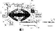
图5是对图4中实施方式的部件所作的类似轴向视图,表示了各个活动部件处于高传动比时的状态;Figure 5 is a similar axial view of the parts of the embodiment of Figure 4, showing the various moving parts at high gear ratios;
图6中的示意图表示了本发明另一实施方式的一个部件,其表示了一种改型的螺旋接合机构;The schematic diagram in Figure 6 shows a component of another embodiment of the present invention, which shows a modified screw joint mechanism;
图7中的轴向剖视图表示了本发明的另一实施方式;An axial sectional view among Fig. 7 shows another embodiment of the present invention;
图8是图7所示实施方式的端视图;Figure 8 is an end view of the embodiment shown in Figure 7;
图9中的轴向剖视图表示了本发明的又一实施方式,该实施方式被设计成既适于重载、又适于大传动比范围;The axial sectional view in Fig. 9 shows yet another embodiment of the invention, which is designed for both heavy loads and large transmission ratio ranges;
图10是图9中实施方式的端视图;Figure 10 is an end view of the embodiment in Figure 9;
图11是图9、10所示实施方式中功率输出器的分解图;以及Figure 11 is an exploded view of the power taker in the embodiment shown in Figures 9 and 10; and
图12中的分解剖视图表示了图9、10实施方式中的内座圈组件。The exploded cross-sectional view in Figure 12 shows the inner race assembly in the embodiment of Figures 9 and 10 .
具体实施方式Detailed ways
参见附图—尤其是图1、2和3,图中所示的传动装置包括一壳体,该壳体在总体上由标号11指代,在该壳体内设置了一径向外侧座圈12,该座圈被制成两个可在轴向上相对移位的部件13、14,它们通过所谓的“滚珠丝杠”而接合到一起,滚珠丝杠包括几行螺旋形排列的滚珠15,这些滚珠接合到两部件13、14上的螺旋槽中,从而使两部件可绕传动装置的中心纵向轴线X-X相对转动。滚珠丝杠具有多道螺旋(在此情况下其头数为4);这样进行设计的原因是:需要用滚珠充满所能获得的空间(以达到最大的负载性能)、但又要避免采用大的滚珠(这样就需要采用单头螺旋);且要使螺旋的导程较长,以便于对轴向载荷和周向载荷进行平衡。通过将部件14安装到固定销16上,可实现两部件13、14之间的相对轴向位移,其中的固定销16形成了一个十字联轴节,壳体内的一对销杆约束着座圈部件14,使其无法转动,但却能在轴向上移动。十字联轴节在此处被用作“误差吸纳”机构,其允许径向平移,但阻止转动。两对销杆在实际上并不像在图中所示那样位于同一平面内,而是被布置成互为90°,图中由叉号代表的小平面位于十字联轴节环的缝槽内。可转动位移的座圈部件13被保持在一个基本为圆筒形的保持器17中,可借助于一调整臂18使保持器17绕轴线X-X转动,而调整臂18的转动则是由一调整致动器10驱动的。致动器10(在图1中可看到其端部)优选为一螺旋致动器,其具有由一电动机(图中未示出)驱动的滚珠丝杠。通过将可转动的座圈部件13绕轴线X-X转动,则该部件自身实际上就会通过滚珠丝杠15的作用而相对于可轴向移动的外座圈部件14“旋进”,使得部件14沿着滑动销16没有转动地轴向移动。按照这样的方式,通过在某个方向或另一方向上旋转可转动的外座圈部件13,就可以使两座圈部件13、14相互移离、或相互靠近。两座圈部件具有弯曲的座圈表面19、20,两座圈表面与行星构件(总体上用标号21指代)的曲面相接合,行星构件包括两个滚子元件,在本案为两近似为半球形的壳体22、23,它们被一中心销24保持在一起,中心销24上安装有一个滚动体轴承25,行星构件21利用该轴承25而支持到一对应的连杆26上。从图2可看出,每一连杆26都被连接到一行星架28的支臂27上,行星架28被固定地连接到一输出轴29上,输出轴29同轴地包绕着输入轴30,并借助于一轴承31支撑到输入轴30上。另一个轴承32也将输入轴30与行星架28连接起来,密封件33、34对装置进行保护,以防止灰尘、泥土和其它污染颗粒、以及湿气或水气进入到装置内部。Referring to the drawings - in particular Figures 1, 2 and 3, the transmission shown in the figures comprises a housing, generally designated by the numeral 11, within which is disposed a radially
行星构件21还在一内座圈上滚动,该内座圈总体上由标号35指代,其包括一个在轴向上固定的座圈部件36、以及一可轴向移动的部件37,它们被安装在一滚珠丝杠38上,该滚珠丝杠类似于将径向外座圈的两部件互相连接起来的构件。一弱的预加载扭转弹簧40将可轴向移动的内座圈部件37推顶向行星构件21,以便于使它们保持接触。The
在上文提到的WO99/35417号国际专利申请中描述了改变传动比的方式,并描述了利用支撑在滚珠丝杠38上的、可轴向移动的径向内侧座圈部件37来测量输入轴与输出轴之间扭矩的方式,其中的座圈部件37被支撑在轴向固定的座圈部件36上的滚珠丝杠38上,下文中,除了与行星构件21形状相关的内容之外,将不再对装置的工作方式进行描述,上述专利的公开内容被结合到本文中作为背景技术。In the above-mentioned International Patent Application No. WO99/35417 the means of changing the transmission ratio are described and the use of an axially movable radially
在上述的早期PCT申请中,行星构件是一个球形的实心球,由于其在径向内座圈和外座圈之间进行运动而产生的作用力是通过位于每对相邻行星构件之间的行星从动件进行传递的。如在所述专利文件中所描述的那样,如果两外座圈部件相互移近、以便于在径向向内的方向上顶推行星构件,则两径向内座圈就被分开,且利用这种对扭矩敏感的结构来保持着接触压力。随着径向外座圈的两个部件接近于最相互接近的位置,行星构件与座圈之间的接触部位就会在径向上向内移动,并且,由于行星构件的形状为球形,则穿过行星构件中心的接触表面法线相对于滚动轴线的倾斜角就会变得更小,从而使作用力的径向分量变小,而轴向分量增大。因而,为了实现较低的传动比,就必须要在行星构件上施加一个非常大的绝对接触力,当然,终久会出现这样的情况:通过另外增大作用力所能实现的另加径向位移量变得较小,但所施加的作用力则大到不可接受的程度。另外,在最高传动比和最低传动比时,最为靠近行星构件转动轴线接触部位就会发生显著的“自旋”,这将增大摩擦接触的发热效应,从而产生出了更多的热量,而这些热量必须要被散出去,以便于将装置保持在可以容许的限度内。但是,在本发明中,与圆球形行星构件的形状相反,行星构件21的构造只采用环周母线中那些最为有效的部分,且由于在两壳体22、23之间存在一环形空间41,所以去掉了构件上的赤道带,并通过两壳体22、23的形状而改变了位于端极区域的形状。从图1可看出,在该实施方式中,在所能达到的最低传动比上,外座圈部件13、14与行星构件21的接触部位最靠近于滚动轴线,此时,在该区域内,接触面的倾斜角度仍然为30°,另外,两接触表面的法线(分别由线段A和B指代)会在某一点处相交,该位置点偏离椭球体的中心,该椭球体是由行星构件的弯曲滚动面围成的。这就限制了接触部位的自旋,使得装置能承受更大的负载。行星构件21通过连杆26与行星架支臂27直接连接,这样的设计由于能在可利用空间内装配更多的行星构件,所以也使得装置能承受更大的负载。In the earlier PCT application mentioned above, the planetary member is a spherical solid ball, and the force due to its movement between the radially inner and outer races is through the The planetary follower performs the transmission. As described in said patent document, if the two outer race parts are moved closer to each other so as to push the planet members in a radially inward direction, the two radially inner races are separated and the This torque-sensitive structure maintains contact pressure. As the two parts of the radially outer race come closer to each other, the point of contact between the planet member and the race moves radially inward and, due to the spherical shape of the planet member, wears The inclination angle of the normal of the contact surface passing through the center of the planet member with respect to the rolling axis becomes smaller, so that the radial component of the acting force becomes smaller and the axial component increases. Thus, in order to achieve a lower transmission ratio, it is necessary to exert a very large absolute contact force on the planetary members. Of course, it will eventually occur that the additional radial displacement that can be achieved by additionally increasing the force The amount becomes smaller, but the applied force becomes unacceptably large. In addition, at the highest transmission ratio and the lowest transmission ratio, a significant "spin" will occur at the contact point closest to the rotation axis of the planetary member, which will increase the heating effect of the frictional contact, thereby generating more heat, while This heat must be dissipated in order to keep the device within tolerable limits. However, in the present invention, contrary to the shape of the spherical planetary member, the construction of the
下面参见图4和图5,图中表示了一种备选的实施方式,在该实施方式中,行星构件为更为显著的扁球体。在图4、5所示的实施方式中,那些与图1到图3所示实施方式中部件相对应、并能完成相同功能的部件被标注为相同的数字标号。但在该实施方式中,行星架的支臂27被与输出轴20制为一体,从而使位于输入轴和行星架之间的轴承32就直接作用在输入轴和输出轴之间,而位于输出轴和外壳之间、且先前在轴向上与轴承32错开的轴承44就将与轴承32在轴向上对齐,这将提高装置的强度。上文中的密封件33、34被密封件43和42所取代,密封件43位于输出轴的端部与输入轴30之间,密封件42保护着轴承44,以防止灰尘、泥土和其它的污染物进入到输出轴29与外壳11之间。Referring now to Figures 4 and 5, an alternative embodiment is shown in which the planet members are more pronounced oblate spheroids. In the embodiments shown in FIGS. 4 and 5 , those components corresponding to those in the embodiments shown in FIGS. 1 to 3 and capable of performing the same functions are marked with the same numerals. However, in this embodiment, the
行星架的支臂27上固定着延长件46,在环绕着内座圈轴向固定部件36端部的邻近位置处,该延长件上安装着一个增强环45。内座圈部件36被外壳11凸台49上的一个轴承48支承着,在凸台49内设置有一个中央插塞50,其具有一沿轴向延伸的通道47,该通道用于将冷却性的润滑剂引流到装置的内部中。插塞50中的通道47通入到一个腔室51中,该腔室位于相互接合着的输入轴50和内座圈35中,并从该通道47延伸出两条径向通道52、53,其中的第一条径向通道52在轴向上对准壳体22、23之间的空间41,从而能将冷却性的润滑剂直接注入到行星构件21与连杆26之间的轴承25中,第二通道(即通道53)通入到输出轴29与输入轴30之间的主轴承32区域中。腔室51也延伸向轴承49,从而可将注入到输入轴30中央通道47中的润滑油直接输送给主轴承49和32、位于径向内侧的滚珠丝杠40、以及行星构件21的轴承25。由润滑剂的强制流动所实现的额外冷却/润滑作用与增强环45的设置、以及行星构件21的扁平形状组合起来,就可使装置达到更高的承载性能。An
从图4可看出,行星构件21高度扁平的椭球体形状确保了接触部位的法线(图4中用点P代表)相对于行星构件21滚动轴线的倾斜角仍然大于45°—即使在最靠近该轴线的情况下。这样,作用力在径向和轴向上的分配可被看作是有利于径向分量的—甚至在径向外座圈12的两部件13、14处于最近位置(见图4)的情况下,且不会对行星构件21与径向内座圈35部件36、37之间相互作用力的轴向分量带来不利影响。类似地,从图5可看出,径向外座圈的两部件13、14在图中处于间隔最大的位置处,则行星构件21与径向内座圈部件36、37之间接触部位P的法线相对于行星构件滚动轴线的夹角仍然保持在45°的范围内,由此,相比于圆球体行星构件下对应作用力的径向分量,上述的设计能有利地增大作用力的径向分量。As can be seen from Fig. 4, the highly flattened ellipsoidal shape of the
可以领会:可在能实现双方向扭矩传递的上述传动装置上应用0016261.0号待审专利申请中所公开的构思,此待审专利申请所公开的内容被结合到本文中作为参考。It will be appreciated that the concepts disclosed in the pending patent application No. 0016261.0, the disclosure of which is incorporated herein by reference, can be applied to the above-described transmission capable of bidirectional torque transmission.
将径向内座圈12和外座圈35的两部件连接起来的滚珠丝杠(例如滚珠丝杠15、38)存在一个相关的问题,该问题在于:滚珠与其容纳滚道之间的打滑或“蠕滑”现象会导致位于滚珠队列端部处的滚珠接合到端部止挡上,且无法进行其正常的滚动。可通过将位于队列两相对端的滚珠设置成与位于螺旋沟道端部区域处的齿牙或锯齿相啮合,来克服上述的缺陷。这样的解决方案并不会牺牲其余滚珠丝杠的承载能力,同时,滚动动作的确定性也保证了滚珠与沟道之间不会出现任何的打滑。A problem associated with ball screws that join two parts of the radially
在图6所示的备选结构中,可利用带有螺旋槽56的滚柱55来取代滚珠,其中的螺旋槽56与一径向外侧部件和一径向内侧部件上的对应螺旋槽57、58相接合,滚柱55被设置在径向外侧部件和内侧部件之间。当然,每一部件上螺旋线的节距和头数是相同的,优选地是,滚柱上具有一单头螺旋,其优选为槽角为90°的三角形螺槽,但也可采用桶形的螺槽,以便于保证接合部具有大的接触半径。由于所有螺槽的节距都是相同的,所以当滚柱在两构件之间滚转时不会在轴向上产生移位,受某一构件上螺槽作用而趋于在某个方向上轴向移动的趋势都会被受滚柱上螺槽作用而在相反方向上轴向移动的趋势所抵消。滚柱的每一端部处都带有齿牙,这些齿牙与两构件上的齿圈相啮合,以此来确保实现正确的滚动运动而不带有任何滑动,其中,滚柱接合在这两个构件之间。In an alternative configuration shown in FIG. 6, the balls may be replaced by rollers 55 having helical grooves 56 which correspond to corresponding helical grooves 57, 57, 58, the roller 55 is arranged between the radially outer part and the inner part. Of course, the pitch and the number of threads of the helix on each part are the same. Preferably, there is a single helix on the roller, which is preferably a triangular groove with a groove angle of 90°, but a barrel shape can also be used. The screw groove in order to ensure that the joint has a large contact radius. Since the pitches of all the grooves are the same, the rollers will not be displaced in the axial direction when they roll between the two components, and tend to move in a certain direction due to the action of the grooves on a certain component. Any tendency to move axially is counteracted by the tendency to move axially in the opposite direction by the grooves on the rollers. The rollers have teeth at each end that mesh with ring gears on the two members to ensure correct rolling motion without any slippage where the rollers engage between components.
下面参见图7、8,图中表示了一种备选的实施方式,该实施方式被设计成能最大可能地利用环周空间,从而能在给定尺寸的装置内装配尽可能多的行星构件。如同在前述的实施方式中一样,使用相同的标号来指代图7和图8中相同或对应的构件。从图8可看出,在与图1所示实施方式具有相同尺寸的前提下,图1中的变速器只具有四个行星构件,而该实施方式的变速器却具有五个行星构件60。在行星构件60环体的中位平面内,这些行星构件通过一个固定到行星架支臂27上的盘板61而与支臂27相连接。盘板61具有基本为径向的宽槽缝62,在这些槽内安装着衬套63,衬套63中容纳着滚动元件的轴承25a、25b,行星构件在这两个轴承上滚动。在改变传动比的运动过程中,衬套63自身也可以在槽缝62中滚转。槽缝62可相对于严格的径向指向偏斜,这就能增大或减小内座圈上的接触力,同时对应地减小或增大外座圈上的接触力。这将是一种有用的设计措施。Referring now to Figures 7 and 8, an alternative embodiment is shown which is designed to make the best possible use of the circumferential space to fit as many planetary members as possible into a given size device . As in the previous embodiments, the same reference numerals are used to designate the same or corresponding components in FIGS. 7 and 8 . It can be seen from FIG. 8 that, under the premise of having the same dimensions as the embodiment shown in FIG. 1 , the transmission in FIG. 1 has only four planetary members, while the transmission in this embodiment has five planetary members 60 . The planetary components 60 are connected to the
该实施方式在圆周方向上是非常紧凑的,并具有很高的负载性能。对盘板61的局部进行了加厚,以便于对由衬套63构成的滚柱提供较宽的支撑,当然,由于盘板61自身就具有非常大的刚度,所以,像图4中实施方式那样从行星架的支臂27延伸出一增强盘并非是必须的。该实施方式还允许输入轴30与输出轴29之间实现双向扭矩传递。为此目的,利用同轴的滚珠丝杠联轴器70、71取代图1中例如位于输入轴30和内座圈右手侧半部件37之间的滚珠丝杠38,其中的联轴器70、71为滚珠队列的形式,这些滚珠与制在输入轴30、以及内座圈左右两半部件36和37中的螺旋线相配合。两滚珠丝杠的螺旋方向是相同的,因而,某一给定方向的扭矩传递工作将使内座圈的两个半部件都趋于沿输入轴30在相同的轴向方向上移动,例如,对于正向的驱动扭矩传递,是受到向左的驱动,而对于超速或负向的驱动扭矩传递,是受到向右的驱动。This embodiment is very compact in the circumferential direction and has a high load capacity. The part of the disc plate 61 is thickened so as to provide wider support for the rollers formed by the
驱动轴30具有一中央法兰盘72,其构成了一个轴肩部,该轴肩带有一个环形的磨损衬垫73,驱动轴30的左侧端上带有一个环形的端部抵接止挡74,该止挡也带有一个对应的环形磨损衬垫75。利用一簧环76将构件74固定住,簧环76接合到驱动轴30端部的一个环形槽中。The
两端部止挡72、74分别与内座圈右左两部件37、36的径向表面相接合。因而,在正向的驱动传递过程中,当两个半座圈36、37都被推向图中的右侧时,抵接件72限制了半座圈37的运动,从而利用半座圈36继续执行的旋拧动作而保持着对行星构件60的挤夹力。与此对应,对于负向的扭矩传递,两个半座圈36、37在各自的滚珠丝杠70、71上移向左侧,直到使半座圈36与端部止挡74相接合为止,滚珠丝杠70继续执行的旋拧动作会将半座圈37推向半座圈36,这同样会保持着对行星构件60的挤夹力。取决于扭矩反向时确切的传动比,座圈部件36、37的位置会有或多或少的明显移位。也就是说,在低传动比的情况下,座圈部件36、37之间的间距最大,因而,它们甚至沿滚珠丝杠70、71未产生任何移位(或至少是非常有限的)。在另一方面,在径向内座圈的两部件36、37最为接近的最高传动比时,两部件相反的径向面与两端部止挡72、74之间的间距最大,从而出现了最大的轴向位移。在扭矩方向改变时,半座圈抵接着对应的端部止挡会产生不可忽略的冲击作用,图9中的实施方式设置了用于消除与此相关缺陷的装置。The end stops 72, 74 engage with the radial surfaces of the right and left
如下文将要详细介绍的那样,图9中的实施方式也如上文所述那样被设计成用于承担重载、并具有很大的速比区间。同样,类同于上面的实施方式,那些与前述实施方式中部件相同或完成相同功能的部件将被标记为与上文相同的数字标号。在该实施方式中,内座圈的部件组(其被具体地表示在图12中)包括两个半座圈36、37,它们利用滚珠丝杠结构、借助于滚珠39(见图9,但在图12中未示出)而安装到输入轴30的一螺杆部分77上。图9所示的实施方式具有两个套环78、79,它们取代了端部止挡72、74,两套环中的前者接合到驱动轴30的法兰盘72上,后者借助于一剪切销(图中未示出)固定到驱动轴30的另一端上,其中的剪切销穿过相互对齐的孔洞80(在驱动轴30上)和孔洞81(在套环79上)。As will be described in detail below, the embodiment in FIG. 9 is also designed to carry heavy loads and has a large speed ratio range as described above. Also, similar to the above embodiments, those components that are the same as those in the previous embodiments or perform the same functions will be marked with the same numerals as above. In this embodiment, the component set of the inner race (which is specifically shown in Figure 12) comprises two half-
为了实现大的速比范围,必须要使驱动轴30的滚珠丝杠部分具有尽可能小的直径。但是,为实现重载却需要驱动轴更为强固。为了分摊载荷,在内座圈的部件36、37与套环79、78之间设置一爪式离合器机构。这一机构包括:位于半座圈36和37上的一些以环形阵列排布的轴向延伸销杆82、83;以及位于套环79和78上的一些以环形阵列排布的销杆84、85。这些销杆的端面是倾斜的,从而使它们至少能在部分上既对扭转载荷、又对轴向载荷产生反作用,应当指出的是:这样制成的爪式离合器的接合动作会使滚道部件36、37在输入轴30的螺杆部分77上产生相对螺旋运动。In order to achieve a large speed ratio range, the ball screw part of the
为了对参照图7所描述的扭矩反向时出现的反冲作用进行缓冲,图9到图12所示的实施方式设置了一对轴向通道86、87,它们由对应的单向阀88、89进行控制,单向阀88、89允许中央通道47内的油液经过对应的径向通道90、从单向阀88、89径向流入到轴向通道86、87中,从而流入到一环形腔室92中,腔室92是由一环形管状套筒93在座圈部件37与套环78之间围成的。左侧的半滚道部件36具有一个类似的环形腔室94,其是由套筒95围成的,用于使润滑油进入到套环79中的通道(图中未示出)中。如果在扭矩反向时座圈被顶推向止挡位置,则腔室92、94中的压力油只能从作为(环形)活塞的套环与由半滚道部件构成的缸筒之间的小缝隙流出。这就可缓冲反冲作用,防止在金属对金属的驱动复位时产生冲击噪音。In order to dampen the backlash that occurs when the torque is reversed as described with reference to FIG. 7, the embodiment shown in FIGS. 89 for control, the check valves 88, 89 allow the oil in the
如图11所示,一普通的行星构件21被作为功率输出系统的部件,该系统包括两个半体行星构件21a、21b,它们被压装到一中心轴21c上,该轴杆首先穿过套筒21d,该套筒的两端处具有合适的圆柱滚针轴承。套筒21d接合到板件61(在该实施方式中,其近似为带有圆拐角的方板)上的一径向槽孔61a中,该槽孔具有沿轴向延伸的侧边61b、61c,以便于提供一个加宽的表面,套筒可在该加宽表面上沿径向滚动一小段距离。板件61通过孔洞61d将其功率传递给行星架27,行星架上的突指27a接合到孔洞61d中。As shown in Figure 11, a common
在上文所有的实施方式中,都可实现一最高传动比,在该传动比时,通过将行星构件径向向外的最大偏移量限制为小于由径向外座圈所允许的量,就可防止接触部位发生自旋,其中,当达到外座圈所允许的量时,两座圈部件之间的分离间距已超过了阈值。In all of the above embodiments, a highest gear ratio can be achieved in which by limiting the maximum radially outward deflection of the planet members to less than that allowed by the radially outer race, This prevents spinning of the contact site where, by the amount permitted by the outer race, the separation distance between the two race parts has exceeded a threshold value.
在图1到图6所示的实施方式中,例如是利用一个安装在行星架上的抵接止挡(图中未示出)来限制连杆26的向外偏移,由此来实现上述的效果。抵接止挡被定位在与行星构件相连接的端部和与行星架相连接的端部之间的某些位置点上。在图7和图8所示的实施方式中,是通过这样的措施来实现上述目的的:确保保持着行星构件的槽缝62径向外端的径向向外偏移量小于由径向外座圈两部件之间最大间距所允许的量。在图9到图12所示的实施方式中,通过在内座圈部件36、37的周边上设置对应的夹圈96、97、并对它们的形状进行设计以使得夹圈能在滚动轴线的径向外侧接合着行星构件21,以此来提供该最高速比锁定限制功能。因而,当径向外座圈13、14分离到它们的最大张开度时,能利用滚珠丝杠39使径向内座圈达到其最为靠近的位置处,两夹圈96、97接合着行星构件21,从而在输入轴与输出轴之间构成了直通驱动。在该结构中,需要在行星构件21与外座圈13、14之间留有间隙,也就是说,在最高的滚动速比与该锁定的最高速比之间存在一个阶跃变化,原因在于此状态下行星构件21是受径向内侧座圈的半部件的顶触而转动。In the embodiment shown in Fig. 1 to Fig. 6, for example, an abutment stopper (not shown in the figures) installed on the planet carrier is used to limit the outward deflection of the connecting
Claims (30)
Translated fromChineseApplications Claiming Priority (2)
| Application Number | Priority Date | Filing Date | Title |
|---|---|---|---|
| GBGB0121739.7AGB0121739D0 (en) | 2001-09-08 | 2001-09-08 | An improved continuously variable transmission |
| GB0121739.7 | 2001-09-08 |
Publications (2)
| Publication Number | Publication Date |
|---|---|
| CN1568407Atrue CN1568407A (en) | 2005-01-19 |
| CN100507313C CN100507313C (en) | 2009-07-01 |
Family
ID=9921746
Family Applications (1)
| Application Number | Title | Priority Date | Filing Date |
|---|---|---|---|
| CNB028199472AExpired - LifetimeCN100507313C (en) | 2001-09-08 | 2002-09-06 | An improved continuously variable transmission device |
Country Status (18)
| Country | Link |
|---|---|
| US (1) | US7125359B2 (en) |
| EP (1) | EP1436529B1 (en) |
| JP (1) | JP4647908B2 (en) |
| KR (1) | KR100875578B1 (en) |
| CN (1) | CN100507313C (en) |
| AT (1) | ATE298052T1 (en) |
| BR (1) | BR0212548B1 (en) |
| CA (1) | CA2460259C (en) |
| DE (1) | DE60204713T2 (en) |
| DK (1) | DK1436529T3 (en) |
| EA (1) | EA005883B1 (en) |
| ES (1) | ES2244797T3 (en) |
| GB (2) | GB0121739D0 (en) |
| GE (1) | GEP20074028B (en) |
| MX (1) | MXPA04002228A (en) |
| NO (1) | NO325925B1 (en) |
| PT (1) | PT1436529E (en) |
| WO (1) | WO2003023256A1 (en) |
Cited By (39)
| Publication number | Priority date | Publication date | Assignee | Title |
|---|---|---|---|---|
| CN102782364A (en)* | 2010-02-22 | 2012-11-14 | 丰田自动车株式会社 | Power transmission device |
| CN101720397B (en)* | 2007-04-24 | 2013-01-02 | 福博科技术公司 | electric traction drive |
| CN103899501A (en)* | 2009-12-18 | 2014-07-02 | 诺迈士科技有限公司 | Gear box and module, shaft, wind turbine, and assembling method thereof |
| CN104776180A (en)* | 2015-04-02 | 2015-07-15 | 四川大学 | Spin-free stepless transmission unit |
| US9574642B2 (en) | 2008-10-14 | 2017-02-21 | Fallbrook Intellectual Property Company Llc | Continuously variable transmission |
| US9618100B2 (en) | 2008-05-07 | 2017-04-11 | Fallbrook Intellectual Property Company Llc | Assemblies and methods for clamping force generation |
| US9677650B2 (en) | 2013-04-19 | 2017-06-13 | Fallbrook Intellectual Property Company Llc | Continuously variable transmission |
| US9676391B2 (en) | 2007-02-01 | 2017-06-13 | Fallbrook Intellectual Property Company Llc | Systems and methods for control of transmission and/or prime mover |
| US9683640B2 (en) | 2008-06-06 | 2017-06-20 | Fallbrook Intellectual Property Company Llc | Infinitely variable transmissions, continuously variable transmissions, methods, assemblies, subassemblies, and components therefor |
| US9683638B2 (en) | 2005-12-30 | 2017-06-20 | Fallbrook Intellectual Property Company Llc | Continuously variable gear transmission |
| US9709138B2 (en) | 2005-11-22 | 2017-07-18 | Fallbrook Intellectual Property Company Llc | Continuously variable transmission |
| US9726282B2 (en) | 2006-06-26 | 2017-08-08 | Fallbrook Intellectual Property Company Llc | Continuously variable transmission |
| US9739375B2 (en) | 2007-12-21 | 2017-08-22 | Fallbrook Intellectual Property Company Llc | Automatic transmissions and methods therefor |
| CN107100990A (en)* | 2012-03-28 | 2017-08-29 | 株式会社久保田 | Paddy field work vehicle |
| US9850993B2 (en) | 2008-02-29 | 2017-12-26 | Fallbrook Intellectual Property Company Llc | Continuously and/or infinitely variable transmissions and methods therefor |
| US9869388B2 (en) | 2007-07-05 | 2018-01-16 | Fallbrook Intellectual Property Company Llc | Continuously variable transmission |
| US9878717B2 (en) | 2008-08-05 | 2018-01-30 | Fallbrook Intellectual Property Company Llc | Systems and methods for control of transmission and/or prime mover |
| US9903450B2 (en) | 2008-08-26 | 2018-02-27 | Fallbrook Intellectual Property Company Llc | Continuously variable transmission |
| US9920823B2 (en) | 2009-04-16 | 2018-03-20 | Fallbrook Intellectual Property Company Llc | Continuously variable transmission |
| US9945456B2 (en) | 2007-06-11 | 2018-04-17 | Fallbrook Intellectual Property Company Llc | Continuously variable transmission |
| US9950608B2 (en) | 2005-10-28 | 2018-04-24 | Fallbrook Intellectual Property Company Llc | Electromotive drives |
| US10036453B2 (en) | 2004-10-05 | 2018-07-31 | Fallbrook Intellectual Property Company Llc | Continuously variable transmission |
| US10047861B2 (en) | 2016-01-15 | 2018-08-14 | Fallbrook Intellectual Property Company Llc | Systems and methods for controlling rollback in continuously variable transmissions |
| US10066712B2 (en) | 2010-03-03 | 2018-09-04 | Fallbrook Intellectual Property Company Llc | Infinitely variable transmissions, continuously variable transmissions, methods, assemblies, subassemblies, and components therefor |
| US10066713B2 (en) | 2008-06-23 | 2018-09-04 | Fallbrook Intellectual Property Company Llc | Continuously variable transmission |
| US10094453B2 (en) | 2007-02-16 | 2018-10-09 | Fallbrook Intellectual Property Company Llc | Infinitely variable transmissions, continuously variable transmissions, methods, assemblies, subassemblies, and components therefor |
| US10100927B2 (en) | 2007-11-16 | 2018-10-16 | Fallbrook Intellectual Property Company Llc | Controller for variable transmission |
| US10197147B2 (en) | 2010-11-10 | 2019-02-05 | Fallbrook Intellectual Property Company Llc | Continuously variable transmission |
| US10208840B2 (en) | 2005-12-09 | 2019-02-19 | Fallbrook Intellectual Property Company Llc | Continuously variable transmission |
| US10260607B2 (en) | 2007-02-12 | 2019-04-16 | Fallbrook Intellectual Property Company Llc | Continuously variable transmissions and methods therefor |
| US10400872B2 (en) | 2015-03-31 | 2019-09-03 | Fallbrook Intellectual Property Company Llc | Balanced split sun assemblies with integrated differential mechanisms, and variators and drive trains including balanced split sun assemblies |
| US10428939B2 (en) | 2003-02-28 | 2019-10-01 | Fallbrook Intellectual Property Company Llc | Continuously variable transmission |
| US10428915B2 (en) | 2012-01-23 | 2019-10-01 | Fallbrook Intellectual Property Company Llc | Infinitely variable transmissions, continuously variable transmissions, methods, assemblies, subassemblies, and components therefor |
| US10458526B2 (en) | 2016-03-18 | 2019-10-29 | Fallbrook Intellectual Property Company Llc | Continuously variable transmissions, systems and methods |
| US11174922B2 (en) | 2019-02-26 | 2021-11-16 | Fallbrook Intellectual Property Company Llc | Reversible variable drives and systems and methods for control in forward and reverse directions |
| US11215268B2 (en) | 2018-11-06 | 2022-01-04 | Fallbrook Intellectual Property Company Llc | Continuously variable transmissions, synchronous shifting, twin countershafts and methods for control of same |
| CN115335616A (en)* | 2020-03-12 | 2022-11-11 | 住友重机械工业株式会社 | friction drive |
| US11667351B2 (en) | 2016-05-11 | 2023-06-06 | Fallbrook Intellectual Property Company Llc | Systems and methods for automatic configuration and automatic calibration of continuously variable transmissions and bicycles having continuously variable transmission |
| US12442434B2 (en) | 2024-06-04 | 2025-10-14 | Enviolo B.V. | Reversible variable drives and systems and methods for control in forward and reverse directions |
Families Citing this family (14)
| Publication number | Priority date | Publication date | Assignee | Title |
|---|---|---|---|---|
| CN1584368A (en)* | 2003-08-20 | 2005-02-23 | 乌尔里克.罗斯 | Continuously variable transmission |
| GB2408081B (en)* | 2003-11-14 | 2008-07-23 | Orbital Traction Ltd | An improved continuously variable transmission device |
| US7086981B2 (en)* | 2004-02-18 | 2006-08-08 | The Gates Corporation | Transmission and constant speed accessory drive |
| DE202005017823U1 (en)* | 2005-11-15 | 2006-01-12 | Deckel Maho Pfronten Gmbh | Ball screw for machine tools |
| GB0609647D0 (en)* | 2006-05-16 | 2006-06-28 | Ellis Christopher W H | Continuously variable transmission device |
| US20080244322A1 (en)* | 2007-03-27 | 2008-10-02 | Tim Kelso | Program Test System |
| US7951035B2 (en)* | 2008-02-07 | 2011-05-31 | American Axle & Manufacturing, Inc. | Continuously variable torque vectoring axle assembly |
| WO2011081866A2 (en)* | 2009-12-14 | 2011-07-07 | Orbital Traction, Ltd. | Systems and methods for operating a driveline system |
| WO2011100499A1 (en)* | 2010-02-12 | 2011-08-18 | The Timken Company | Epicyclical gear transmission with improved load carrying capability |
| US9631563B2 (en) | 2010-06-30 | 2017-04-25 | Orbital Traction, Ltd | Torque pulse dampener |
| AU2012240435B2 (en) | 2011-04-04 | 2016-04-28 | Fallbrook Intellectual Property Company Llc | Auxiliary power unit having a continuously variable transmission |
| EP2764305A2 (en) | 2011-10-03 | 2014-08-13 | Fallbrook Intellectual Property Company LLC | Refrigeration system having a continuously variable transmission |
| US10486523B2 (en) | 2018-02-13 | 2019-11-26 | Ford Global Technologies, Llc | Hybrid transmission with variator |
| US11009118B1 (en)* | 2019-10-24 | 2021-05-18 | John Matthew Hawkins | Epicyclic gearing torque reduction mechanism |
Family Cites Families (12)
| Publication number | Priority date | Publication date | Assignee | Title |
|---|---|---|---|---|
| DE560276C (en)* | 1927-05-19 | 1932-09-30 | Richard Shelmo Jacobsen | Friction roller change gear |
| US2209497A (en)* | 1938-08-23 | 1940-07-30 | Guy H Hall | Variable ratio transmission |
| US3516305A (en)* | 1968-05-09 | 1970-06-23 | Walter Valdemar Chery | Torque converter |
| US3670595A (en)* | 1969-12-17 | 1972-06-20 | Walter Valdemar Chery | Variable speed automatic transmission |
| US3618423A (en)* | 1970-06-08 | 1971-11-09 | Walter V Chery | Transmission |
| US3793910A (en) | 1972-10-02 | 1974-02-26 | A Nasvytis | Variable speed friction drive |
| GB1586779A (en)* | 1976-12-16 | 1981-03-25 | Galbraith Eng Pty Ltd | Variable speed epicyclic transmission devices |
| US4158317A (en)* | 1978-01-16 | 1979-06-19 | James Robert G | Infinite ratio transmission |
| DE4126993A1 (en)* | 1991-08-16 | 1993-02-18 | Fichtel & Sachs Ag | Drive hub for a vehicle, especially a bicycle, with a continuously variable transmission ratio. |
| US5390558A (en)* | 1993-05-03 | 1995-02-21 | Weinberg; Morgan W. | Continuously variable transmission |
| DE69911916T2 (en)* | 1998-01-12 | 2004-08-19 | Orbital Traction Ltd., Hinckley | CONTINUOUSLY ADJUSTABLE GEARBOX |
| GB9915416D0 (en)* | 1999-07-02 | 1999-09-01 | Milner Peter J | A continuously variable drive transmission device |
- 2001
- 2001-09-08GBGBGB0121739.7Apatent/GB0121739D0/ennot_activeCeased
- 2002
- 2002-09-06USUS10/488,821patent/US7125359B2/ennot_activeExpired - Lifetime
- 2002-09-06GEGE5558Apatent/GEP20074028B/enunknown
- 2002-09-06EPEP02758568Apatent/EP1436529B1/ennot_activeExpired - Lifetime
- 2002-09-06PTPT02758568Tpatent/PT1436529E/enunknown
- 2002-09-06ESES02758568Tpatent/ES2244797T3/ennot_activeExpired - Lifetime
- 2002-09-06ATAT02758568Tpatent/ATE298052T1/ennot_activeIP Right Cessation
- 2002-09-06CNCNB028199472Apatent/CN100507313C/ennot_activeExpired - Lifetime
- 2002-09-06WOPCT/GB2002/004065patent/WO2003023256A1/enactiveIP Right Grant
- 2002-09-06DEDE60204713Tpatent/DE60204713T2/ennot_activeExpired - Lifetime
- 2002-09-06GBGB0220741Apatent/GB2381839A/ennot_activeWithdrawn
- 2002-09-06MXMXPA04002228Apatent/MXPA04002228A/enactiveIP Right Grant
- 2002-09-06CACA002460259Apatent/CA2460259C/ennot_activeExpired - Lifetime
- 2002-09-06DKDK02758568Tpatent/DK1436529T3/enactive
- 2002-09-06BRBRPI0212548-0Apatent/BR0212548B1/ennot_activeIP Right Cessation
- 2002-09-06JPJP2003527292Apatent/JP4647908B2/ennot_activeExpired - Lifetime
- 2002-09-06EAEA200400419Apatent/EA005883B1/ennot_activeIP Right Cessation
- 2002-09-06KRKR1020047003456Apatent/KR100875578B1/ennot_activeExpired - Fee Related
- 2004
- 2004-03-22NONO20041202Apatent/NO325925B1/ennot_activeIP Right Cessation
Cited By (64)
| Publication number | Priority date | Publication date | Assignee | Title |
|---|---|---|---|---|
| US10428939B2 (en) | 2003-02-28 | 2019-10-01 | Fallbrook Intellectual Property Company Llc | Continuously variable transmission |
| US10036453B2 (en) | 2004-10-05 | 2018-07-31 | Fallbrook Intellectual Property Company Llc | Continuously variable transmission |
| US9950608B2 (en) | 2005-10-28 | 2018-04-24 | Fallbrook Intellectual Property Company Llc | Electromotive drives |
| US9709138B2 (en) | 2005-11-22 | 2017-07-18 | Fallbrook Intellectual Property Company Llc | Continuously variable transmission |
| US10711869B2 (en) | 2005-11-22 | 2020-07-14 | Fallbrook Intellectual Property Company Llc | Continuously variable transmission |
| US11454303B2 (en) | 2005-12-09 | 2022-09-27 | Fallbrook Intellectual Property Company Llc | Continuously variable transmission |
| US10208840B2 (en) | 2005-12-09 | 2019-02-19 | Fallbrook Intellectual Property Company Llc | Continuously variable transmission |
| US11598397B2 (en) | 2005-12-30 | 2023-03-07 | Fallbrook Intellectual Property Company Llc | Continuously variable gear transmission |
| US9683638B2 (en) | 2005-12-30 | 2017-06-20 | Fallbrook Intellectual Property Company Llc | Continuously variable gear transmission |
| US9726282B2 (en) | 2006-06-26 | 2017-08-08 | Fallbrook Intellectual Property Company Llc | Continuously variable transmission |
| US9676391B2 (en) | 2007-02-01 | 2017-06-13 | Fallbrook Intellectual Property Company Llc | Systems and methods for control of transmission and/or prime mover |
| US9878719B2 (en) | 2007-02-01 | 2018-01-30 | Fallbrook Intellectual Property Company Llc | Systems and methods for control of transmission and/or prime mover |
| US10703372B2 (en) | 2007-02-01 | 2020-07-07 | Fallbrook Intellectual Property Company Llc | Systems and methods for control of transmission and/or prime mover |
| US10260607B2 (en) | 2007-02-12 | 2019-04-16 | Fallbrook Intellectual Property Company Llc | Continuously variable transmissions and methods therefor |
| US10094453B2 (en) | 2007-02-16 | 2018-10-09 | Fallbrook Intellectual Property Company Llc | Infinitely variable transmissions, continuously variable transmissions, methods, assemblies, subassemblies, and components therefor |
| US9574643B2 (en) | 2007-04-24 | 2017-02-21 | Fallbrook Intellectual Property Company Llc | Electric traction drives |
| US10056811B2 (en) | 2007-04-24 | 2018-08-21 | Fallbrook Intellectual Property Company Llc | Electric traction drives |
| CN101720397B (en)* | 2007-04-24 | 2013-01-02 | 福博科技术公司 | electric traction drive |
| US9945456B2 (en) | 2007-06-11 | 2018-04-17 | Fallbrook Intellectual Property Company Llc | Continuously variable transmission |
| US10260629B2 (en) | 2007-07-05 | 2019-04-16 | Fallbrook Intellectual Property Company Llc | Continuously variable transmission |
| US9869388B2 (en) | 2007-07-05 | 2018-01-16 | Fallbrook Intellectual Property Company Llc | Continuously variable transmission |
| US11125329B2 (en) | 2007-11-16 | 2021-09-21 | Fallbrook Intellectual Property Company Llc | Controller for variable transmission |
| US10100927B2 (en) | 2007-11-16 | 2018-10-16 | Fallbrook Intellectual Property Company Llc | Controller for variable transmission |
| US9739375B2 (en) | 2007-12-21 | 2017-08-22 | Fallbrook Intellectual Property Company Llc | Automatic transmissions and methods therefor |
| US10704687B2 (en) | 2007-12-21 | 2020-07-07 | Fallbrook Intellectual Property Company Llc | Automatic transmissions and methods therefor |
| US9850993B2 (en) | 2008-02-29 | 2017-12-26 | Fallbrook Intellectual Property Company Llc | Continuously and/or infinitely variable transmissions and methods therefor |
| US9618100B2 (en) | 2008-05-07 | 2017-04-11 | Fallbrook Intellectual Property Company Llc | Assemblies and methods for clamping force generation |
| US10634224B2 (en) | 2008-06-06 | 2020-04-28 | Fallbrook Intellectual Property Company Llc | Infinitely variable transmissions, continuously variable transmissions, methods, assemblies, subassemblies, and components therefor |
| US9683640B2 (en) | 2008-06-06 | 2017-06-20 | Fallbrook Intellectual Property Company Llc | Infinitely variable transmissions, continuously variable transmissions, methods, assemblies, subassemblies, and components therefor |
| US10066713B2 (en) | 2008-06-23 | 2018-09-04 | Fallbrook Intellectual Property Company Llc | Continuously variable transmission |
| US9878717B2 (en) | 2008-08-05 | 2018-01-30 | Fallbrook Intellectual Property Company Llc | Systems and methods for control of transmission and/or prime mover |
| US10704657B2 (en) | 2008-08-26 | 2020-07-07 | Fallbrook Intellectual Property Company Llc | Continuously variable transmission |
| US9903450B2 (en) | 2008-08-26 | 2018-02-27 | Fallbrook Intellectual Property Company Llc | Continuously variable transmission |
| US10253880B2 (en) | 2008-10-14 | 2019-04-09 | Fallbrook Intellectual Property Company Llc | Continuously variable transmission |
| US9574642B2 (en) | 2008-10-14 | 2017-02-21 | Fallbrook Intellectual Property Company Llc | Continuously variable transmission |
| US10746270B2 (en) | 2009-04-16 | 2020-08-18 | Fallbrook Intellectual Property Company Llc | Continuously variable transmission |
| US9920823B2 (en) | 2009-04-16 | 2018-03-20 | Fallbrook Intellectual Property Company Llc | Continuously variable transmission |
| CN103899501A (en)* | 2009-12-18 | 2014-07-02 | 诺迈士科技有限公司 | Gear box and module, shaft, wind turbine, and assembling method thereof |
| CN103899501B (en)* | 2009-12-18 | 2016-09-07 | 诺迈士科技有限公司 | Gear box structure and module, axle, wind-driven generator and assemble method |
| CN102782364A (en)* | 2010-02-22 | 2012-11-14 | 丰田自动车株式会社 | Power transmission device |
| US10066712B2 (en) | 2010-03-03 | 2018-09-04 | Fallbrook Intellectual Property Company Llc | Infinitely variable transmissions, continuously variable transmissions, methods, assemblies, subassemblies, and components therefor |
| US10197147B2 (en) | 2010-11-10 | 2019-02-05 | Fallbrook Intellectual Property Company Llc | Continuously variable transmission |
| US10428915B2 (en) | 2012-01-23 | 2019-10-01 | Fallbrook Intellectual Property Company Llc | Infinitely variable transmissions, continuously variable transmissions, methods, assemblies, subassemblies, and components therefor |
| CN107100990A (en)* | 2012-03-28 | 2017-08-29 | 株式会社久保田 | Paddy field work vehicle |
| CN107100990B (en)* | 2012-03-28 | 2020-04-10 | 株式会社久保田 | Paddy field working vehicle |
| US9677650B2 (en) | 2013-04-19 | 2017-06-13 | Fallbrook Intellectual Property Company Llc | Continuously variable transmission |
| US10323732B2 (en) | 2013-04-19 | 2019-06-18 | Fallbrook Intellectual Property Company Llc | Continuously variable transmission |
| US10400872B2 (en) | 2015-03-31 | 2019-09-03 | Fallbrook Intellectual Property Company Llc | Balanced split sun assemblies with integrated differential mechanisms, and variators and drive trains including balanced split sun assemblies |
| CN104776180B (en)* | 2015-04-02 | 2017-08-04 | 四川大学 | A spinless stepless speed change unit |
| CN104776180A (en)* | 2015-04-02 | 2015-07-15 | 四川大学 | Spin-free stepless transmission unit |
| US10920882B2 (en) | 2016-01-15 | 2021-02-16 | Fallbrook Intellectual Property Company Llc | Systems and methods for controlling rollback in continuously variable transmissions |
| US11306818B2 (en) | 2016-01-15 | 2022-04-19 | Fallbrook Intellectual Property Company Llc | Systems and methods for controlling rollback in continuously variable transmissions |
| US10047861B2 (en) | 2016-01-15 | 2018-08-14 | Fallbrook Intellectual Property Company Llc | Systems and methods for controlling rollback in continuously variable transmissions |
| US10458526B2 (en) | 2016-03-18 | 2019-10-29 | Fallbrook Intellectual Property Company Llc | Continuously variable transmissions, systems and methods |
| US11667351B2 (en) | 2016-05-11 | 2023-06-06 | Fallbrook Intellectual Property Company Llc | Systems and methods for automatic configuration and automatic calibration of continuously variable transmissions and bicycles having continuously variable transmission |
| US12145690B2 (en) | 2016-05-11 | 2024-11-19 | Enviolo B.V. | Systems and methods for automatic configuration and automatic calibration of continuously variable transmissions and bicycles having continuously variable transmissions |
| US11215268B2 (en) | 2018-11-06 | 2022-01-04 | Fallbrook Intellectual Property Company Llc | Continuously variable transmissions, synchronous shifting, twin countershafts and methods for control of same |
| US11624432B2 (en) | 2018-11-06 | 2023-04-11 | Fallbrook Intellectual Property Company Llc | Continuously variable transmissions, synchronous shifting, twin countershafts and methods for control of same |
| US12173778B2 (en) | 2018-11-06 | 2024-12-24 | Enviolo B.V. | Continuously variable transmissions, synchronous shifting, twin countershafts and methods for control of same |
| US11174922B2 (en) | 2019-02-26 | 2021-11-16 | Fallbrook Intellectual Property Company Llc | Reversible variable drives and systems and methods for control in forward and reverse directions |
| US11530739B2 (en) | 2019-02-26 | 2022-12-20 | Fallbrook Intellectual Property Company Llc | Reversible variable drives and systems and methods for control in forward and reverse directions |
| US12000458B2 (en) | 2019-02-26 | 2024-06-04 | Fallbrook Intellectual Property Company Llc | Reversible variable drives and systems and methods for control in forward and reverse directions |
| CN115335616A (en)* | 2020-03-12 | 2022-11-11 | 住友重机械工业株式会社 | friction drive |
| US12442434B2 (en) | 2024-06-04 | 2025-10-14 | Enviolo B.V. | Reversible variable drives and systems and methods for control in forward and reverse directions |
Also Published As
| Publication number | Publication date |
|---|---|
| GB0121739D0 (en) | 2001-10-31 |
| EA200400419A1 (en) | 2004-10-28 |
| NO20041202L (en) | 2004-06-07 |
| KR100875578B1 (en) | 2008-12-23 |
| US7125359B2 (en) | 2006-10-24 |
| KR20040044867A (en) | 2004-05-31 |
| BR0212548B1 (en) | 2011-12-13 |
| DE60204713D1 (en) | 2005-07-21 |
| PT1436529E (en) | 2005-11-30 |
| EA005883B1 (en) | 2005-06-30 |
| DE60204713T2 (en) | 2006-08-24 |
| JP2005502841A (en) | 2005-01-27 |
| GEP20074028B (en) | 2007-02-12 |
| WO2003023256A1 (en) | 2003-03-20 |
| ATE298052T1 (en) | 2005-07-15 |
| JP4647908B2 (en) | 2011-03-09 |
| GB2381839A (en) | 2003-05-14 |
| GB0220741D0 (en) | 2002-10-16 |
| US20040248689A1 (en) | 2004-12-09 |
| CA2460259C (en) | 2009-05-05 |
| BR0212548A (en) | 2004-10-13 |
| DK1436529T3 (en) | 2005-10-17 |
| EP1436529B1 (en) | 2005-06-15 |
| CN100507313C (en) | 2009-07-01 |
| NO325925B1 (en) | 2008-08-18 |
| MXPA04002228A (en) | 2005-02-17 |
| EP1436529A1 (en) | 2004-07-14 |
| HK1074477A1 (en) | 2005-11-11 |
| ES2244797T3 (en) | 2005-12-16 |
| CA2460259A1 (en) | 2003-03-20 |
Similar Documents
| Publication | Publication Date | Title |
|---|---|---|
| CN1568407A (en) | An improved continuously variable transmission device | |
| CN1157546C (en) | Drive Mechanism of Continuously Variable Transmission | |
| CN1260498C (en) | friction drive | |
| JP2002513889A (en) | Rolling contact continuously variable transmission | |
| US9322441B2 (en) | Clamping element freewheel | |
| CN1144959C (en) | Lubricating oil supply device for continuously variable transmission | |
| CN101371062A (en) | Frey friction gear | |
| CN1230639C (en) | Differential device | |
| CN1066524C (en) | Stepless transmitter | |
| US6893351B2 (en) | Tripod type constant velocity universal joint | |
| CN1070994A (en) | Hydraulic slider coupling | |
| JP5695504B2 (en) | Damper pulley | |
| US20160047457A1 (en) | Shaft supporting structure of belt-driven continuously variable transmission | |
| CN1105250C (en) | Tensioner for imparting tension to force transmitting member | |
| CN103671623B (en) | Free wheel | |
| US6206801B1 (en) | Continuously variable transmission | |
| KR0149455B1 (en) | Differential drive mechanism | |
| JP2975940B2 (en) | Differential transmission | |
| HK1074477B (en) | An improved continuously variable transmission device | |
| JP2019190549A (en) | Slide-type constant velocity universal joint for propeller shaft | |
| CN104006090B (en) | Actuator for a group of internal combustion engines provided with a sleeve connection acting through a helical orifice | |
| KR100627668B1 (en) | Tripod joint assembly and its assembly method | |
| JP6766382B2 (en) | Toroidal continuously variable transmission | |
| CN1346944A (en) | Stepless speed change device | |
| CN1346945A (en) | Stepless speed change device |
Legal Events
| Date | Code | Title | Description |
|---|---|---|---|
| C06 | Publication | ||
| PB01 | Publication | ||
| C10 | Entry into substantive examination | ||
| SE01 | Entry into force of request for substantive examination | ||
| REG | Reference to a national code | Ref country code:HK Ref legal event code:DE Ref document number:1074477 Country of ref document:HK | |
| C14 | Grant of patent or utility model | ||
| GR01 | Patent grant | ||
| REG | Reference to a national code | Ref country code:HK Ref legal event code:GR Ref document number:1074477 Country of ref document:HK | |
| C41 | Transfer of patent application or patent right or utility model | ||
| TR01 | Transfer of patent right | Effective date of registration:20151223 Address after:Texas, USA Patentee after:Intel Xin Technology Co.,Ltd. Address before:Leicestershire Patentee before:Orbital Traction Ltd. Effective date of registration:20151223 Address after:Texas, USA Patentee after:Orbital Traction Ltd. Address before:Texas, USA Patentee before:Intel Xin Technology Co.,Ltd. | |
| CX01 | Expiry of patent term | ||
| CX01 | Expiry of patent term | Granted publication date:20090701 |