CN1552015A - Durable touch screen - Google Patents
Durable touch screenDownload PDFInfo
- Publication number
- CN1552015A CN1552015ACNA028174348ACN02817434ACN1552015ACN 1552015 ACN1552015 ACN 1552015ACN A028174348 ACNA028174348 ACN A028174348ACN 02817434 ACN02817434 ACN 02817434ACN 1552015 ACN1552015 ACN 1552015A
- Authority
- CN
- China
- Prior art keywords
- resin sheet
- transparent resin
- heat
- resistant transparent
- electrode plate
- Prior art date
- Legal status (The legal status is an assumption and is not a legal conclusion. Google has not performed a legal analysis and makes no representation as to the accuracy of the status listed.)
- Granted
Links
Images


Classifications
- G—PHYSICS
- G06—COMPUTING OR CALCULATING; COUNTING
- G06F—ELECTRIC DIGITAL DATA PROCESSING
- G06F3/00—Input arrangements for transferring data to be processed into a form capable of being handled by the computer; Output arrangements for transferring data from processing unit to output unit, e.g. interface arrangements
- G06F3/01—Input arrangements or combined input and output arrangements for interaction between user and computer
- G06F3/03—Arrangements for converting the position or the displacement of a member into a coded form
- G06F3/041—Digitisers, e.g. for touch screens or touch pads, characterised by the transducing means
- G06F3/045—Digitisers, e.g. for touch screens or touch pads, characterised by the transducing means using resistive elements, e.g. a single continuous surface or two parallel surfaces put in contact
- G—PHYSICS
- G06—COMPUTING OR CALCULATING; COUNTING
- G06F—ELECTRIC DIGITAL DATA PROCESSING
- G06F3/00—Input arrangements for transferring data to be processed into a form capable of being handled by the computer; Output arrangements for transferring data from processing unit to output unit, e.g. interface arrangements
- G06F3/01—Input arrangements or combined input and output arrangements for interaction between user and computer
- G06F3/03—Arrangements for converting the position or the displacement of a member into a coded form
- G06F3/041—Digitisers, e.g. for touch screens or touch pads, characterised by the transducing means
- G—PHYSICS
- G02—OPTICS
- G02F—OPTICAL DEVICES OR ARRANGEMENTS FOR THE CONTROL OF LIGHT BY MODIFICATION OF THE OPTICAL PROPERTIES OF THE MEDIA OF THE ELEMENTS INVOLVED THEREIN; NON-LINEAR OPTICS; FREQUENCY-CHANGING OF LIGHT; OPTICAL LOGIC ELEMENTS; OPTICAL ANALOGUE/DIGITAL CONVERTERS
- G02F1/00—Devices or arrangements for the control of the intensity, colour, phase, polarisation or direction of light arriving from an independent light source, e.g. switching, gating or modulating; Non-linear optics
- G02F1/01—Devices or arrangements for the control of the intensity, colour, phase, polarisation or direction of light arriving from an independent light source, e.g. switching, gating or modulating; Non-linear optics for the control of the intensity, phase, polarisation or colour
- G02F1/13—Devices or arrangements for the control of the intensity, colour, phase, polarisation or direction of light arriving from an independent light source, e.g. switching, gating or modulating; Non-linear optics for the control of the intensity, phase, polarisation or colour based on liquid crystals, e.g. single liquid crystal display cells
- G02F1/133—Constructional arrangements; Operation of liquid crystal cells; Circuit arrangements
- G02F1/1333—Constructional arrangements; Manufacturing methods
- G02F1/13338—Input devices, e.g. touch panels
- G—PHYSICS
- G06—COMPUTING OR CALCULATING; COUNTING
- G06F—ELECTRIC DIGITAL DATA PROCESSING
- G06F3/00—Input arrangements for transferring data to be processed into a form capable of being handled by the computer; Output arrangements for transferring data from processing unit to output unit, e.g. interface arrangements
- G06F3/01—Input arrangements or combined input and output arrangements for interaction between user and computer
- G06F3/03—Arrangements for converting the position or the displacement of a member into a coded form
- G06F3/041—Digitisers, e.g. for touch screens or touch pads, characterised by the transducing means
- G06F3/0412—Digitisers structurally integrated in a display
- H—ELECTRICITY
- H01—ELECTRIC ELEMENTS
- H01B—CABLES; CONDUCTORS; INSULATORS; SELECTION OF MATERIALS FOR THEIR CONDUCTIVE, INSULATING OR DIELECTRIC PROPERTIES
- H01B5/00—Non-insulated conductors or conductive bodies characterised by their form
- H01B5/14—Non-insulated conductors or conductive bodies characterised by their form comprising conductive layers or films on insulating-supports
- H—ELECTRICITY
- H01—ELECTRIC ELEMENTS
- H01H—ELECTRIC SWITCHES; RELAYS; SELECTORS; EMERGENCY PROTECTIVE DEVICES
- H01H13/00—Switches having rectilinearly-movable operating part or parts adapted for pushing or pulling in one direction only, e.g. push-button switch
- H01H13/70—Switches having rectilinearly-movable operating part or parts adapted for pushing or pulling in one direction only, e.g. push-button switch having a plurality of operating members associated with different sets of contacts, e.g. keyboard
- H01H13/702—Switches having rectilinearly-movable operating part or parts adapted for pushing or pulling in one direction only, e.g. push-button switch having a plurality of operating members associated with different sets of contacts, e.g. keyboard with contacts carried by or formed from layers in a multilayer structure, e.g. membrane switches
- H01H13/703—Switches having rectilinearly-movable operating part or parts adapted for pushing or pulling in one direction only, e.g. push-button switch having a plurality of operating members associated with different sets of contacts, e.g. keyboard with contacts carried by or formed from layers in a multilayer structure, e.g. membrane switches characterised by spacers between contact carrying layers
- H—ELECTRICITY
- H01—ELECTRIC ELEMENTS
- H01H—ELECTRIC SWITCHES; RELAYS; SELECTORS; EMERGENCY PROTECTIVE DEVICES
- H01H2201/00—Contacts
- H01H2201/018—Contacts transparent
- H—ELECTRICITY
- H01—ELECTRIC ELEMENTS
- H01H—ELECTRIC SWITCHES; RELAYS; SELECTORS; EMERGENCY PROTECTIVE DEVICES
- H01H2209/00—Layers
- H01H2209/046—Properties of the spacer
- H01H2209/06—Properties of the spacer transparent
Landscapes
- Engineering & Computer Science (AREA)
- Physics & Mathematics (AREA)
- General Engineering & Computer Science (AREA)
- Theoretical Computer Science (AREA)
- General Physics & Mathematics (AREA)
- Human Computer Interaction (AREA)
- Nonlinear Science (AREA)
- Crystallography & Structural Chemistry (AREA)
- Chemical & Material Sciences (AREA)
- Mathematical Physics (AREA)
- Optics & Photonics (AREA)
- Polarising Elements (AREA)
- Push-Button Switches (AREA)
- Position Input By Displaying (AREA)
- Liquid Crystal (AREA)
- Laminated Bodies (AREA)
Abstract
Description
Translated fromChinese技术领域technical field
本发明涉及一种触摸屏,其即使被长时间放置在高温环境中也不会引起由滞后变化而导致的抗反射特性的降低,还能进行舒适的输入操作,在进行组装时操作性良好并具有高耐久性。该触摸屏主要被用于汽车导航等领域。The present invention relates to a touch panel that does not cause a decrease in anti-reflection characteristics due to hysteresis changes even if it is left in a high-temperature environment for a long time, can perform comfortable input operations, has good operability when assembling, and has high durability. The touch screen is mainly used in fields such as car navigation.
背景技术Background technique
一直以来,触摸屏就被配备在被PDA(个人数字助理)、手机以及个人计算机等制品广泛使用的LCD、有机EL、CRT等显示器的前面。触摸屏的基本结构为,在下表面设有由透明导电膜构成的上部电极的上部电极板,和在上表面设有由透明导电膜构成的下部电极的下部电极板,两电极通过空气层相向设置且两电极板仅在显示区域外粘结固定,由空气层绝缘的两电极通过按压屏幕的一部分而接触导电从而可以进行输入。而且,上述上部电极板及上述下部电极板分别由单层构成或由多层全面粘结层叠构成。Conventionally, touch screens have been installed in front of displays such as LCDs, organic ELs, and CRTs that are widely used in products such as PDAs (Personal Digital Assistants), mobile phones, and personal computers. The basic structure of the touch screen is an upper electrode plate with an upper electrode made of a transparent conductive film on the lower surface, and a lower electrode plate with a lower electrode made of a transparent conductive film on the upper surface. The two electrode plates are bonded and fixed only outside the display area, and the two electrodes insulated by the air layer are contacted and electrically conductive by pressing a part of the screen so that input can be performed. Furthermore, the above-mentioned upper electrode plate and the above-mentioned lower electrode plate are each composed of a single layer or a multi-layer laminated by full-surface bonding.
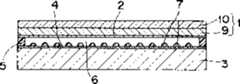
于是,针对在室外使用的用途,为了防止外光线的反射从而提高能见性,可以使用低反射的触摸屏(参见图4),该触摸屏的上述上部电极板1从上述上部电极2侧开始至少顺序层叠有1/4波片9、以及上述1/4波片9的光轴与吸收轴成45°或135°的偏振光片10。由1/4波片9和偏振光片10形成圆偏振光型抗反射滤光片,大幅缩减外部入射光在透明导电膜上的反射。另外,当显示器是LCD时,如果只有一枚1/4波片9,则从LCD侧作为显示用途入射的直线偏振光也将转变为圆偏振光,因此更进一步,通过将上述上部电极板中的1/4波片9与光轴正交的1/4波片配备在下部电极板3中以使相位消除。也就是说,通过下部电极4侧的1/4波片被变成圆偏振光后,通过上部电极2侧的1/4波片9再次变回原来的直线偏振光。Therefore, for the purpose of using outdoors, in order to prevent the reflection of external light and improve visibility, a low-reflection touch screen (see FIG. 4 ) can be used. The above-mentioned upper electrode plate 1 of the touch screen starts from the above-mentioned
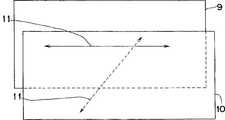
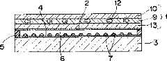
近年来汽车业内正在普及汽车导航,其主要通过遥控器进行画面操作,但为了能更舒适地进行操作而将触摸屏用在显示器画面上也被予以考虑。在这种情况下,为了防止由太阳光等室外光反射导致的能见性变差的问题,有上述圆偏振光型抗反射滤光片的触摸屏就成为了必要。但是,在夏天阳光直射下,车窗密闭的车内温度超过70℃以上的高温环境也是存在的。长时间地放置在这种环境中就会引起膨胀,由于上部电极板1中的1/4波片9和偏振光片10的轴形成时的拉伸方向不同,所以存在在直接或间接全面贴合的状态下呈现互相不同的膨胀方向11(参看图5),在触摸屏的上部电极板1上产生褶皱和翘棱的危险。并且,在上述高温环境下,由于上部电极板1中的1/4波片9的膨胀在中央部分虽然是不受约束的,但与之相对的边缘部分由于受到和下部电极板3部分地粘结固定的影响,1/4波片9的膨胀就会受到阻挡或与之相反被迫过分地膨胀,所以存在仅有1/4波片9的的边缘部分会受到压力12(参看图6)且显示区域边缘部分附近的1/4波片9的滞后值发生变化而损害抗发射特性的危险。In recent years, car navigation has been popularized in the automotive industry, and the screen is mainly operated by a remote controller, but it is also considered to use a touch panel on the display screen for more comfortable operation. In such a case, in order to prevent deterioration of visibility due to reflection of outdoor light such as sunlight, a touch panel with the above-mentioned circularly polarized antireflection filter becomes necessary. However, under direct sunlight in summer, a high-temperature environment in which the temperature inside a car with closed windows exceeds 70° C. also exists. Long-term placement in this environment will cause swelling. Since the 1/4
为此,作为汽车导航的用途,为了不产生上述问题,在上部电极板1中配备有玻璃片13且其与1/4波片9全面贴合(参看图7)。通过在上部电极板1中玻璃片与1/4波片9的全面贴合,即使在超过70℃以上的高温环境中,基本不会引起1/4波片9和偏振光片10的热膨胀,所以保持了没有褶皱和翘棱的状态。并且,通过将刚性高的玻璃片全面贴合在1/4波片9上,1/4波片9受到的压力得以分散,所以基本不会引起滞后变化,损害抗反射特性的情况也很少。For this reason, in order to avoid the above-mentioned problems in car navigation applications, a
然而,上部电极板1是手指及笔等直接接触的部分,在上部电极板1中使用玻璃片,由于玻璃片的刚性高,厚度如太厚则用手指及笔进行输入时就会变得更使劲。为了能舒适地进行输入操作,有必要将玻璃厚度设定得非常薄。可是,由于使用这种厚度的玻璃片会变得非常易碎,所以组装触摸屏时的处理就变得非常困难,并且也有在进行触摸屏输入操作时玻璃破损的可能性。However, the upper electrode plate 1 is a part that is in direct contact with fingers, pens, etc., and a glass sheet is used in the upper electrode plate 1. Since the glass sheet has high rigidity, if the thickness is too thick, it will become more difficult when inputting with fingers and pens. strain. In order to perform input operations comfortably, it is necessary to set the glass thickness to be extremely thin. However, since a glass sheet of such a thickness becomes very fragile, it becomes very difficult to handle when assembling the touch panel, and there is also a possibility that the glass is broken during an input operation on the touch panel.
因而,本发明的目的就在于解决上述问题,提供一种耐久性高的触摸屏,其即使被长时间放置在高温环境中也不会引起外观形状的改变和由滞后变化而导致的抗反射特性的降低,并且还能进行舒适的输入,而且在进行组装时也具有良好的操作性。Therefore, the object of the present invention is to solve the above-mentioned problems, and to provide a highly durable touch panel that does not cause changes in appearance and shape and damage to anti-reflection characteristics caused by hysteresis changes even if it is placed in a high-temperature environment for a long time. It can be lowered, and it can also perform comfortable input, and it also has good operability when performing assembly.
发明内容Contents of the invention
本发明为了达到上述目的,具有以下结构。In order to achieve the above object, the present invention has the following structures.
根据本发明的第1技术方案,一种耐久性高的触摸屏,其具有在下表面设有由透明导电膜构成的上部电极的上部电极板,和在上表面设有由透明导电膜构成的下部电极的下部电极板,两电极通过空气层相向设置且上述两电极板仅在显示区域外粘结固定,上述上部电极板从上述上部电极侧开始至少顺序层叠有1/4波片、以及上述1/4波片的光轴与吸收轴成45°或135°的偏振光片,该触摸屏的上述上部电极板具有特性为玻璃化温度在150℃以上吸水率在1.3%以下且厚度在0.15~0.8mm的光各向同性的耐热透明树脂片,上述耐热透明树脂片被直接或间接地全面贴合在上述1/4波片上。According to a first aspect of the present invention, a highly durable touch panel has an upper electrode plate provided with an upper electrode made of a transparent conductive film on the lower surface, and a lower electrode made of a transparent conductive film provided on the upper surface. The lower electrode plate, the two electrodes are arranged facing each other through the air layer, and the above two electrode plates are bonded and fixed only outside the display area, and the above-mentioned upper electrode plate has at least sequentially stacked 1/4 wave plate and the above-mentioned 1/4 wave plate from the side of the above-mentioned upper electrode. 4. A polarizing plate whose optical axis and absorption axis are 45° or 135°. The above-mentioned upper electrode plate of the touch screen has the characteristics that the glass transition temperature is above 150°C, the water absorption rate is below 1.3%, and the thickness is 0.15-0.8mm An optically isotropic heat-resistant transparent resin sheet, the above-mentioned heat-resistant transparent resin sheet is directly or indirectly laminated on the above-mentioned 1/4 wave plate.
根据本发明的第2技术方案,如第1技术方案所述的耐久性高的触摸屏,其上述耐热透明树脂片配备在上述1/4波片和上述偏振光片之间。According to a second aspect of the present invention, in the highly durable touch panel according to the first aspect, the heat-resistant transparent resin sheet is provided between the quarter wave plate and the polarizer.
根据本发明的第3技术方案,如第1技术方案所述的耐久性高的触摸屏,其上述耐热透明树脂片配备在上述1/4波片的下方。According to a third aspect of the present invention, in the highly durable touch panel according to the first aspect, the heat-resistant transparent resin sheet is disposed below the quarter-wave plate.
根据本发明的第4技术方案,如第1技术方案所述的耐久性高的触摸屏,其上述耐热透明树脂片配备在上述偏振光片的上方。According to a fourth aspect of the present invention, in the highly durable touch panel according to the first aspect, the heat-resistant transparent resin sheet is disposed above the polarizing sheet.
根据本发明的第5技术方案,如技术方案第1~第4任一项所述的耐久性高的触摸屏,其上述耐热透明树脂片的玻璃化温度在170℃以上。According to a fifth aspect of the present invention, in the highly durable touch panel according to any one of the first to fourth aspects, the glass transition temperature of the heat-resistant transparent resin sheet is 170° C. or higher.
根据本发明的第6技术方案,如技术方案第1~第4任一项所述的耐久性高的触摸屏,其上述耐热透明树脂片的厚度在0.2~0.7mm。According to the sixth technical solution of the present invention, in the highly durable touch panel according to any one of the first to fourth technical solutions, the thickness of the above-mentioned heat-resistant transparent resin sheet is 0.2-0.7 mm.
根据本发明的第7技术方案,如技术方案第1~第4任一项所述的耐久性高的触摸屏,其上述耐热透明树脂片的吸水率在1%以下。According to a seventh aspect of the present invention, in the highly durable touch panel according to any one of the first to fourth aspects, the heat-resistant transparent resin sheet has a water absorption rate of 1% or less.
根据本发明的第8技术方案,如技术方案第1~第4任一项所述的耐久性高的触摸屏,其在作为上述上部电极板最上层的上述偏振光片或上述耐热透明树脂片上配备有作为带有低反射防污功能无光泽层的防湿PET薄膜。According to an eighth aspect of the present invention, the highly durable touch panel according to any one of the first to fourth aspects of the present invention is formed on the polarizer or the heat-resistant transparent resin sheet that is the uppermost layer of the upper electrode plate. Equipped with a moisture-proof PET film as a matte layer with a low-reflection antifouling function.
根据本发明的第9技术方案,如技术方案第1~第4任一项所述的耐久性高的触摸屏,还包括至少覆盖上述上部电极板的侧端周围和上述下部电极板的侧端附近的密封层。According to the ninth technical solution of the present invention, the highly durable touch panel according to any one of the first to fourth technical solutions further includes covering at least around the side ends of the upper electrode plate and around the side ends of the lower electrode plate. sealing layer.
附图说明Description of drawings
本发明这些及其他的目的和特征将通过结合关于附图的理想的实施方式说明清楚。在本附图中:These and other objects and features of the present invention will be clarified with reference to the preferred embodiments with reference to the accompanying drawings. In this attached drawing:
图1是表示与本发明实施方式1有关的具有高耐久性的低反射触摸屏的截面图;1 is a cross-sectional view showing a highly durable low-reflection touch panel related to Embodiment 1 of the present invention;
图2是表示与本发明实施方式2有关的具有高耐久性的低反射触摸屏的截面图;2 is a cross-sectional view showing a highly durable low-reflection touch panel related to
图3是表示与本发明实施方式3有关的具有高耐久性的低反射触摸屏的截面图;3 is a cross-sectional view showing a highly durable low-reflection touch panel related to
图4是表示与现有技术有关的低反射触摸屏的截面图;4 is a cross-sectional view showing a low-reflection touch screen related to the prior art;
图5是表示关于图4的低反射触摸屏的上部电极板在高温环境下的变化的分解平面图;5 is an exploded plan view showing changes in an upper electrode plate of the low-reflection touch screen of FIG. 4 under a high-temperature environment;
图6是表示关于图4的低反射触摸屏的上部电极板在高温环境下受到的压力的截面图;6 is a cross-sectional view showing the pressure on the upper electrode plate of the low-reflection touch screen of FIG. 4 under a high-temperature environment;
图7是表示与现有技术有关的具有高耐久性的低反射触摸屏的截面图;7 is a cross-sectional view showing a low-reflection touch panel with high durability related to the prior art;
图8是表示与本发明其他实施方式有关的具有高耐久性的低反射触摸屏的截面图;8 is a cross-sectional view showing a highly durable low-reflection touch panel related to another embodiment of the present invention;
图9是表示与本发明再其他实施方式有关的具有高耐久性的低反射触摸屏的截面图。9 is a cross-sectional view showing a highly durable low-reflection touch panel according to yet another embodiment of the present invention.
具体实施方式Detailed ways
在继续本发明的说明之前,在附图中,关于相同的部件采用相同的引用符号。Before continuing the description of the present invention, in the drawings, the same reference signs are used for the same components.
下面参照附图详细说明本发明。图1~图3是表示与本发明的实施方式1~3有关的具有高耐久性的低反射触摸屏的截面图。图中,1是上部电极板,2是上部电极,3是下部电极板,4是下部电极,5是作为一例的两面胶带等的粘着层,6是空气层,7是间隔块,8是耐热透明树脂片,9是1/4波片,10是偏振光片。The present invention will be described in detail below with reference to the accompanying drawings. 1 to 3 are cross-sectional views showing highly durable low-reflection touch panels according to Embodiments 1 to 3 of the present invention. In the figure, 1 is an upper electrode plate, 2 is an upper electrode, 3 is a lower electrode plate, 4 is a lower electrode, 5 is an adhesive layer such as double-sided tape as an example, 6 is an air layer, 7 is a spacer block, and 8 is a resistance Thermally transparent resin sheet, 9 is a 1/4 wave plate, 10 is a polarizer.
触摸屏的基本结构为,在下表面设有由透明导电膜构成的上部电极2的上部电极板1,和在上表面设有由透明导电膜构成的下部电极4的下部电极板3,两电极1和3通过空气层6相向设置且两电极板仅在显示区域外粘结固定。当是圆偏振光方式的低反射触摸屏时,作为上述上部电极板1,采用了从上述上部电极2侧开始至少顺序层叠有1/4波片9、以及上述1/4波片9的光轴与吸收轴成45°或135°的偏振光片10的电极板。并且,上述上部电极板1及上述下部电极板3分别由单层构成或由多层全面粘结层叠构成。本发明的实施方式1~3的特征为,这样的低反射触摸屏,其上述上部电极板1具有特性为玻璃化温度在150℃以上且厚度在0.15~0.8mm的光各向同性的耐热透明树脂片8,上述耐热透明树脂片8被直接或间接地全面贴合在上述1/4波片9上(参看图1~图3)。另外,本发明的各实施方式中的“板/片”也包含薄板及薄膜等薄的物体。The basic structure of the touch screen is an upper electrode plate 1 with an
上述1/4波片9,通过对由直线偏振光分解的两个互相正交的偏振光分量施加时间上的相位偏移(相位差),而具有将直线偏振光变为圆偏振光或类圆偏振光的功能,一偏振光分量比另一偏振光分量仅滞后1/4波长。该1/4波长是针对可见光范围(约400nm~700nm)的中心波长(约550nm)的波长。作为1/4波片9,采用了单轴拉伸聚碳酸酯、聚芳酯、聚醚砜、聚砜或冰片烯系树脂等的透明树脂片,具有通过控制作为该拉伸方向(光轴方向)的x方向的折射率、正交于x方向的y方向的折射率、以及厚度方向即正交于x方向和y方向的z方向的折射率而得到的折射率。The above-mentioned 1/4
1/4波片9和其上的偏振光片10组合形成圆偏振光型抗反射滤光片。由于室内的日光灯和室外光线等外部而来的光线穿过偏振光片10变成直线偏振光、通过穿过1/4波片9而变成圆偏振光、即使在透明导电膜反射,圆偏振光再次穿过1/4波片9就会变成与偏振光片10的透射轴垂直的直线偏振光,所以可以抑制反射光。另外,1/4波片9具有使由笔及手指的输入变得容易的可挠性。The 1/4
配备在1/4波片9上面的偏振光片10的吸收轴,是按照与1/4波片9的光轴7成45°或135°来生成的。作为偏振光片10,一般采用,拉伸被碘、染料等双色性色素浸泡过的聚乙烯醇板,在其两面覆盖有纤维素或丙烯系的保护膜的物体等。The absorption axis of the
上述1/4波片9与上述偏振光片10,或/和,上述1/4波片9与上述耐热透明树脂片8被直接全面贴合是可以的(参看图1~图3),通过光各向同性的透明树脂片被间接贴合也是可以的。作为贴合用的粘接剂,有丙烯酸酯共聚合体等的丙烯系树脂、尿烷系树脂、硅系树脂、橡胶系树脂、水性或UV硬化粘接剂。作为上述光各向同性的透明树脂片的材料,聚碳酸酯、聚芳酯、聚醚砜、聚砜或冰片烯系树脂等透明性优异的材料是理想的。另外,本发明上述实施方式中的光各向同性,是指滞后值在10nm以下,最理想是在5nm以下。It is possible for the above-mentioned 1/4
作为上述耐热透明树脂片8的材料,是采用从聚碳酸酯树脂、冰片烯系树脂、环氧系树脂、硅氧烷系树脂、聚芳酯树脂、聚醚砜树脂、聚砜树脂或紫外线硬化丙烯树脂、再或者环氧丙烯树脂等耐热丙烯树脂等光各向同性的透明树脂中,把玻璃化温度在150℃以上的制成厚度在0.15~0.8mm的树脂片。As the material of the above-mentioned heat-resistant
本发明上述实施方式的耐热透明树脂片8,作为上部电极板1的一个结构层与1/4波片9及偏振光片10全面贴合,由此和玻璃片一样,即使在象夏天直射阳光下,车窗密闭的汽车内超过70℃那样的高温环境中,或雨天等湿度超过80%的高温高湿环境下,也基本可以抑制1/4波片9及偏振光片10的热膨胀,而被保持在一种不生成褶皱和翘棱的稳定状态。从而,即使在上述高温或高湿度的环境下也不会受热变形的材料是必要的。该指标是指玻璃化温度和吸水率,如果是玻璃化温度在150℃以上、吸水率在1.3%以下的光各向同性的透明树脂片,那么就可以作为本发明各个实施方式的耐热透明树脂片8来使用。更理想的是采用玻璃化温度在170℃以上的耐热透明树脂片8。此处,使耐热透明树脂片8的吸水率在1.3%以下的理由是,耐热透明树脂片8的吸水率如果超过1.3%的话,通过偏振光片10沁入的水份或从侧面沁入的水份,有引起耐热透明树脂片8变形的可能性,耐热透明树脂片8一旦变形,就不能借助耐热透明树脂片8来支撑偏振光片10及1/4波片9。并且,根据上述理由,伴随耐热透明树脂片8也有引起上部电极板变形而与下部电极板接触从而导致绝缘性降低的可能性。对此,通过将耐热透明树脂片8的吸水率降到1.3%以下,即使耐热透明树脂片8发生一些变形,上部电极板1也不会与下部电极板3接触,所以不会引起触摸屏性能上的问题。The heat-resistant
进而,耐热透明树脂片8的吸水率在上述1.3%以下的基础上达到1%以下更理想。理由为通过将耐热透明树脂片8的吸水率降到1%以下,通过偏振光片10沁入的水份或从侧面沁入的水份基本不会引起耐热透明树脂片8的变形,借助耐热透明树脂片8就可以达到更加可靠地支撑偏振光片10及1/4波片9的目的。Furthermore, the water absorption of the heat-resistant
与此相对,由于到目前为止还没有这样的耐热透明树脂片,偏振光片一旦吸水,会引起由于吸水而造成的偏振光片变形,1/4波片不能抵抗该压力,也就引起了上部电极板的变形。作为结果,就有发生由滞后变化导致的颜色不均匀的危险。并且,变形的上部电极板与下部电极板的接触而引起的绝缘性的降低等情况,导致触摸屏性能故障。In contrast, since there is no such heat-resistant transparent resin sheet so far, once the polarizer absorbs water, it will cause deformation of the polarizer due to water absorption, and the 1/4 wave plate cannot resist the pressure, which also causes Deformation of the upper electrode plate. As a result, there is a risk of color unevenness caused by hysteresis changes. In addition, the contact between the deformed upper electrode plate and the lower electrode plate results in a reduction in insulation performance, which leads to a failure in the performance of the touch panel.
与此相对,本实施方式中,如上所述,通过配备吸水率在1.3%以下的耐热透明树脂片8,由于耐热透明树脂片8没有受到多少通过偏振光片10沁入的水份的影响,从而难以引起耐热透明树脂片8的变形,由于可以针对偏振光片10的膨胀及变形保持其压力,上部电极板1与下部电极板3没有接触,所以不会损害触摸屏的性能。On the other hand, in the present embodiment, as described above, by providing the heat-resistant
并且,为使1/4波片9及偏振光片10不生成褶皱和翘棱的稳定状态得以保持,上述耐热透明树脂片8的厚度在0.15mm以上也是必要的。因为如果玻璃化温度达到了150℃以上但厚度未满0.15mm,虽然耐热透明树脂片8自身不会因为受热而变形,但这个厚度承受不了1/4波片9及偏振光片10将要变形而产生的力量。更理想的是使用厚度在0.2mm以上的耐热透明树脂片8。In addition, in order to maintain a stable state in which the 1/4
并且,如果本发明各实施方式的耐热透明树脂片8的厚度都设定在0.8mm以下的话,由于其可挠性比玻璃片高,所以即使作为上述上部电极板1的一结构层被组装进来也可以轻松地进行笔及手指的输入。更理想的是使用厚度在0.7mm以下的耐热透明树脂片8。而且,由于树脂片不象玻璃片那样易碎,所以组装触摸屏时的操作也就变得非常容易,并且没有在触摸屏输入操作时破损的可能性。并且,滚轧加工也成为了可能,贴合时的除泡处理也容易进行。And, if the thickness of the heat-resistant
下述表1为,在尺寸为130mm×100mm、玻璃化温度为195℃的上述耐热透明树脂片A~C及玻璃片的上面中央放置φ20mm的钢球加压时的挠度值表。The following table 1 is a table of deflection values when a φ20mm steel ball is placed in the center of the above-mentioned heat-resistant transparent resin sheets A-C and glass sheets with a size of 130mm×100mm and a glass transition temperature of 195°C.
表1Table 1

同等厚度的耐热透明树脂片A与玻璃片在静压相同的条件下,挠度值相差3倍。并且,厚度为0.2mm的玻璃片,与厚度是上限0.8mm的厚耐热透明树脂片C相比,玻璃片的挠度值要小,为了能进行轻松的输入操作将厚度设定在0.2mm以下是必要的,而作为结果玻璃片就变得非常易碎。The deflection value of heat-resistant transparent resin sheet A and glass sheet of the same thickness is 3 times different under the same static pressure condition. In addition, a glass sheet with a thickness of 0.2 mm has a smaller deflection value than a thick heat-resistant transparent resin sheet C with a thickness of 0.8 mm, and the thickness is set to 0.2 mm or less for easy input operations. is necessary, and as a result the glass sheet becomes very brittle.
上述耐热透明树脂片8,在上部电极板1中,可以配备在上述1/4波片9和上述偏振光片10之间(参看图3),也可以配备在上述1/4波片9的上部电极2侧(参看图1),另外还可以配备在上述偏振光片10的上部电极2的相反侧(参看图2)。并且,在这些场合,耐热透明树脂片8与1/4波片9和偏振光片10之间也可以有光各向同性的透明树脂片介入。The above-mentioned heat-resistant
作为上部电极2设在如上的上部电极板1下面的透明导电膜的材料,可以使用氧化锡、氧化铟、氧化锑、氧化锌、氧化镉,或ITO等金属氧化物和、金、银、铜、锡、镍、铝,或钯等金属薄膜。作为透明导电膜的向上述上部电极板1的生成方法,可采用真空蒸镀法、溅射法、离子镀膜法、或CVD法等。对于作为下部电极4设在下部电极板3上面的透明导电膜也是同样的。As the material of the transparent conductive film on which the
下面对下部电极板3进行说明。下部电极板3是由单层构成或由多层全面粘结层叠构成的。可以使用例如上述有光各向同性的透明树脂片、玻璃片或它们的层叠体。并且,当显示器是LCD的场合,只有一枚1/4波片9,则从LCD侧作为显示用途入射的直线偏振光也就被转变为了圆偏振光,更进一步,通过将上述上部电极板1中的1/4波片9与光轴正交的1/4波片配备在下部电极板3中以使相位消除。这种情况下,下部电极板3可以由1/4波片单层构成,也可以由有光各向同性的透明树脂片和与玻璃片的层叠体构成。另外,即使是当显示器是LCD的场合,如果该LCD的表面设有两枚1/4波片,也不用在本发明上述实施方式的触摸屏的下部电极板3中设置两枚1/4波片。Next, the
并且,设有上部电极2的上述上部电极板1和设有下部电极4的上述下部电极板3,通常由两面胶带和透明粘接剂等的粘着层5只粘结固定显示区域以外的区域,显示区域则留有空气层6。这种情况下,由于上述1/4波片9与下部电极板3直接地或通过有光各向同性的透明树脂片间接地仅在显示区域外粘结固定,所以为了维持低反射触摸屏的抗反射特性,就必须在高温环境下,仅在1/4波片9的边缘部分不受到压力。本发明的上述实施方式中,由于上述上部电极板1有先前说明的耐热透明树脂片8,上述耐热透明树脂片8直接或间接地全面贴合在上述1/4波片9上,所以施加在1/4波片9的压力就可以得到分散,也基本不会引起滞后变化。于是,损害抗反射特性的情况也就很少发生。In addition, the above-mentioned upper electrode plate 1 provided with the
并且,在触摸屏的面积很大的情况下,为了防止设有上部电极2的上部电极板1由于自身重量与设有下部电极4的下部电极板3接触,就在上部电极2或下部电极4中任一的表面生成微小粒状的间隔块7。可以将透明的光硬化树脂施加光学处理来形成微小粒状的该间隔块7。并且,也可以通过印刷法来形成多数微小颗粒作为间隔块7。And, when the area of the touch screen is very large, in order to prevent the upper electrode plate 1 provided with the
而且,可以对上部电极板1的最上层的偏振光片10或上述耐热透明树脂片8施加低反射处理、防污处理和无光泽处理。或者,可以将实施过这些处理的薄膜,作为带有低反射防污功能的无光泽层20,通过粘接剂等贴合在偏振光片10或上述耐热透明树脂片8上(参看图1及图2的点划线)。在此,作为低反射处理可以举出,涂敷使用了氟树脂和硅树脂等的低反射材料的方法,或对金属的多层膜通过真空蒸镀法或溅射法等来形成。上述薄膜具有保湿性是比较理想了。比如,可以使用厚度在40μm~80μm的PET(聚对苯二甲酸乙二醇酯)薄膜,在偏振光片10或上述耐热透明树脂片8上形成带有防湿低反射防污功能的无光泽层20。由于PET薄膜防湿性优异,所以通过将其贴在偏振光片10上面,可以防止水份进入上部电极板1。也可以使用通过事先热处理而收缩率变低的PET薄膜。防污处理可以举出涂敷使用了氟树脂等的防污材料的方法。无光泽处理可以举出喷砂加工、轧纹加工、无光涂层加工、或蚀刻加工等方法。Furthermore, low-reflection treatment, anti-fouling treatment, and matte treatment may be applied to the uppermost polarizing
在图1~图3的上述实施方式1~3中,更理想的是图3的结构,通过将耐热透明树脂片8配备在偏振光片10和1/4波片9之间耐热透明树脂片8就成为各光学片的支撑片,即使在高温高湿的环境中偏振光片10和1/4波片9的膨胀也会被抑制,难以引起滞后变化和光学特性的劣化。并且,图1、图2的实施方式1和2中,由于偏振光片10和1/4波片9是被直接贴合在一起的,所以与图3的结构相比就比较容易引起褶皱和翘棱,在这种情况下,针对图2的结构,通过增大耐热透明树脂片8的厚度可以得到适宜的相应措施。In the above-mentioned Embodiments 1 to 3 of FIGS. 1 to 3 , the structure of FIG. 3 is more ideal, by disposing a heat-resistant
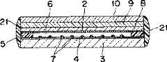
进而,作为本发明的其他实施方式,如图8所示,在上部电极板1和下部电极板3的形状大致一致的场合,可以覆盖上部电极板1和下部电极板3的侧端周围涂敷密封材料以形成密封层21。并且,作为本发明的另一实施方式,如图9所示,在上部电极板1比下部电极板3小的场合,可以覆盖上部电极板1端部周围和下部电极板3的边缘周围涂敷密封材料以形成密封层22。作为密封材料的种类,理想的是采用UV硬化树脂、热硬化UV硬化并用的硬化树脂、丙烯系树脂、环氧系树脂、尿烷系树脂,或,硅系等热硬化树脂。作为密封方法,可举出调制法。这样,借助密封层21、22,可以防止水份从上部电极板1等的端部沁入,防止两面胶带或透明粘结材料等构成的粘着层5的劣化。在高温高温环境中不易受到影响,而且即使是使上部电极板1和下部电极板3粘结的由两面胶带或透明粘结材料等构成的粘着层5剥落,由于还有密封层21、22的保持,触摸屏的特性也不会受损。Furthermore, as another embodiment of the present invention, as shown in FIG. 8 , when the shapes of the upper electrode plate 1 and the
根据上述各实施方式,在有圆偏振光型抗反射滤光片的触摸屏中,由于上部电极板1具有特性为玻璃化温度在150℃以上厚度在0.15~0.8mm的光各向同性的耐热透明树脂片8,上述耐热透明树脂片8被直接或间接地全面贴合在上述1/4波片9上,所以与玻璃片一样,即使在象夏天直射阳光下,车窗密闭的汽车内超过70℃那样的高温环境中,也基本可以抑制1/4波片9及偏振光片10的热膨胀,而被保持在一种不发生褶皱和翘棱的稳定状态。并且,上述耐热透明树脂片8被直接或间接地全面贴合在上述1/4波片9上,所以与玻璃片一样,即使在上述高温环境中,施加在上述1/4波片9的压力就可以得到分散,也基本不会引起滞后变化。于是,损害抗反射特性的情况也就很少发生。According to each of the above-mentioned embodiments, in the touch panel with circularly polarized anti-reflection filter, since the upper electrode plate 1 has a glass transition temperature of 150° C. The
所以,即使被长时间放置在高温环境中也不会引起外观形状的改变和由滞后变化而导致的抗反射特性的降低,并且还能进行舒适的输入,而且具有在进行组装时操作性良好的高耐久性。Therefore, even if it is left in a high-temperature environment for a long time, it will not cause a change in appearance shape and a decrease in anti-reflection characteristics due to hysteresis changes, and it can also perform comfortable input, and has good operability when assembling. high durability.
进而,由于耐热透明树脂片8的可挠性比玻璃片高,笔及手指的输入可以变得轻松,可以进行舒适的输入。Furthermore, since the heat-resistant
而且,由于耐热透明树脂片8不象玻璃片那样易碎,所以组装触摸屏时的操作也就变得非常容易,并且没有在触摸屏输入操作时玻璃破损的可能性。Moreover, since the heat-resistant
进而,即使被长时间放置在高温环境中也不会引起外观形状的改变和由滞后变化而导致的抗反射特性的降低,并且还能进行舒适的输入,而且具有在进行组装时操作性良好的高耐久性。Furthermore, even if it is left in a high-temperature environment for a long time, it will not cause a change in appearance shape or a decrease in anti-reflection characteristics due to hysteresis changes, and it can also perform comfortable input, and has good operability when assembling. high durability.
本发明的耐久性高的触摸屏由于由上述结构构成,所以有以下效果。Since the highly durable touch panel of the present invention has the above structure, it has the following effects.
在有圆偏振光型抗反射滤光片的触摸屏中,由于上部电极板具有特性为玻璃化温度在150℃以上厚度在0.15~0.8mm的光各向同性的耐热透明树脂片,上述耐热透明树脂片被直接或间接地全面贴合在上述1/4波片上,所以与玻璃片一样,即使在象夏天直射阳光下车窗密闭的汽车内超过70℃那样的高温环境中,也基本可以抑制1/4波片及偏振光片的热膨胀,而被保持在一种不生成褶皱和翘棱的稳定状态。并且,上述耐热透明树脂片被直接或间接地全面贴合在上述1/4波片上,所以与玻璃片一样,即使在上述高温环境中,施加在上述1/4波片的压力就可以得到分散,也基本不会引起滞后变化。于是,损害抗反射特性的情况也就很少发生。In a touch screen with a circularly polarized anti-reflection filter, since the upper electrode plate has an optically isotropic heat-resistant transparent resin sheet with a glass transition temperature above 150°C and a thickness of 0.15-0.8mm, the above-mentioned heat-resistant The transparent resin sheet is directly or indirectly bonded to the above-mentioned 1/4 wave plate, so, like the glass sheet, it can basically be used in a high-temperature environment such as a car with closed windows under direct sunlight in summer exceeding 70°C. The thermal expansion of the 1/4 wave plate and the polarizer is suppressed, and it is maintained in a stable state without wrinkles and warping. In addition, the above-mentioned heat-resistant transparent resin sheet is directly or indirectly bonded to the entire surface of the above-mentioned 1/4 wave plate, so even in the above-mentioned high-temperature environment, the pressure applied to the above-mentioned 1/4 wave plate can be obtained, just like the glass sheet. Scattering, basically does not cause hysteresis changes. Thus, impairing of the anti-reflection characteristics rarely occurs.
并且,由于耐热透明树脂片的可挠性比玻璃片高,笔及手指的输入可以变得轻松,可以进行舒适的输入。In addition, since the heat-resistant transparent resin sheet is more flexible than the glass sheet, input with a pen or finger becomes easy and comfortable input is possible.
而且,借助吸水率在1.3%以下的耐热透明树脂片,由于耐热透明树脂片没有受到多少通过偏振光片沁入的水份的影响,所以难以引起耐热透明树脂片的变形,可以针对偏振光片的膨胀及变形保持其压力,由于上部电极板与下部电极板没有接触,所以不会损害触摸屏的性能。此处,耐热透明树脂片的吸水率在1.3%以下的原因为,耐热透明树脂片的吸水率如果超过1.3%的话,通过偏振光片沁入的水份或从侧面沁入的水份,有引起耐热透明树脂片变形的可能性。耐热透明树脂片一旦变形,就不能借助耐热透明树脂片来支撑偏振光片及1/4波片。并且,根据上述理由,与耐热透明树脂片一起也有引起上部电极板变形而与下部电极板接触从而导致绝缘性降低的可能性。针对与此,通过将耐热透明树脂片的吸水率降到1.3%以下,即使耐热透明树脂片发生一些变形上部电极板也不会与下部电极板接触,所以不会引起触摸屏性能上的问题。And, by means of the heat-resistant transparent resin sheet below 1.3% of water absorption, because the heat-resistant transparent resin sheet is not subjected to the influence of how much moisture penetrates through the polarizer, it is difficult to cause the deformation of the heat-resistant transparent resin sheet, which can be aimed at The expansion and deformation of the polarizer maintains its pressure, and since the upper electrode plate is not in contact with the lower electrode plate, it will not damage the performance of the touch screen. Here, the reason why the water absorption rate of the heat-resistant transparent resin sheet is 1.3% or less is that if the water absorption rate of the heat-resistant transparent resin sheet exceeds 1.3%, the water that penetrates through the polarizer or the water that penetrates from the side , there is a possibility of causing deformation of the heat-resistant transparent resin sheet. Once the heat-resistant transparent resin sheet is deformed, the polarizer and the 1/4 wave plate cannot be supported by the heat-resistant transparent resin sheet. Furthermore, for the above reasons, together with the heat-resistant transparent resin sheet, the upper electrode plate may be deformed and may come into contact with the lower electrode plate, resulting in a decrease in insulation. On the other hand, by reducing the water absorption rate of the heat-resistant transparent resin sheet to 1.3% or less, even if the heat-resistant transparent resin sheet is slightly deformed, the upper electrode plate will not come into contact with the lower electrode plate, so it will not cause problems in touch panel performance. .
进而,耐热透明树脂片的吸水率在上述1.3%以下时达到1%以下更理想。理由为通过将吸水率降到1%以下,通过偏振光片沁入的水份或从侧面沁入的水份基本不会引起耐热透明树脂片的变形,借助耐热透明树脂片就可以达到更加可靠地支撑偏振光片及1/4波片的目的。Furthermore, the water absorption of the heat-resistant transparent resin sheet is more preferably 1% or less when it is the above-mentioned 1.3% or less. The reason is that by reducing the water absorption rate to below 1%, the water infiltrated through the polarizer or the water infiltrated from the side will basically not cause deformation of the heat-resistant transparent resin sheet, which can be achieved by means of the heat-resistant transparent resin sheet. The purpose of supporting polarizers and 1/4 wave plates more reliably.
与此相对,由于到目前为止还没有这样的耐热透明树脂片,偏振光片一旦吸水,会引起由于吸水而造成的偏振光片变形,1/4波片不能抵抗该压力,也就引起了上部电极板的变形。作为结果,就有发生由滞后变化导致的颜色不均匀的危险。并且,变形的上部电极板与下部电极板的接触而引起的绝缘性的降低等情况,导致触摸屏性能故障。类似问题可以通过本发明得以解决。In contrast, since there is no such heat-resistant transparent resin sheet so far, once the polarizer absorbs water, it will cause deformation of the polarizer due to water absorption, and the 1/4 wave plate cannot resist the pressure, which also causes Deformation of the upper electrode plate. As a result, there is a risk of color unevenness caused by hysteresis changes. In addition, the contact between the deformed upper electrode plate and the lower electrode plate results in a reduction in insulation performance, which leads to a failure in the performance of the touch panel. Similar problems can be solved by the present invention.
而且,由于耐热透明树脂片不象玻璃片那样易碎,所以组装触摸屏时的操作也就变得非常容易,并且没有在触摸屏输入操作时玻璃破损的可能性。Moreover, since the heat-resistant transparent resin sheet is not as fragile as a glass sheet, the operation when assembling the touch panel becomes very easy, and there is no possibility of glass breakage during the input operation of the touch panel.
另外,通过适当组合上述各种实施方式,可以达到各种各样的效果。In addition, various effects can be achieved by appropriately combining the various embodiments described above.
本发明虽然通过参照附图并结合理想的实施方式得到了详细的记载,但对于本领域的技术人员来说本发明还有多种变形及修改。这些变形及修改只要不是在所附权利要求所要求保护的本发明范围之外,应当理解为被包含在本发明的范围之内。Although the present invention has been described in detail with reference to the attached drawings and with reference to the ideal embodiment, the present invention has various variations and modifications for those skilled in the art. These variations and modifications should be understood as being included in the scope of the present invention as long as they are not outside the scope of the present invention claimed by the appended claims.
Claims (9)
Translated fromChineseApplications Claiming Priority (2)
| Application Number | Priority Date | Filing Date | Title |
|---|---|---|---|
| JP269749/2001 | 2001-09-06 | ||
| JP2001269749 | 2001-09-06 |
Publications (2)
| Publication Number | Publication Date |
|---|---|
| CN1552015Atrue CN1552015A (en) | 2004-12-01 |
| CN1307516C CN1307516C (en) | 2007-03-28 |
Family
ID=19095513
Family Applications (1)
| Application Number | Title | Priority Date | Filing Date |
|---|---|---|---|
| CNB028174348AExpired - Fee RelatedCN1307516C (en) | 2001-09-06 | 2002-09-05 | Touch panel having high durability |
Country Status (6)
| Country | Link |
|---|---|
| US (1) | US7589798B2 (en) |
| EP (1) | EP1424625A4 (en) |
| KR (1) | KR100919077B1 (en) |
| CN (1) | CN1307516C (en) |
| TW (1) | TW571226B (en) |
| WO (1) | WO2003023594A1 (en) |
Cited By (5)
| Publication number | Priority date | Publication date | Assignee | Title |
|---|---|---|---|---|
| CN100340963C (en)* | 2005-01-11 | 2007-10-03 | 松下电器产业株式会社 | Touch panel |
| CN102809828A (en)* | 2011-06-01 | 2012-12-05 | 索尼公司 | Polarization module and image display apparatus |
| CN104932750A (en)* | 2015-06-30 | 2015-09-23 | 京东方科技集团股份有限公司 | Touch screen and manufacturing method thereof and touch display device |
| CN105122190A (en)* | 2013-04-10 | 2015-12-02 | 日本瑞翁株式会社 | Display device with capacitive touch panel |
| CN107924096A (en)* | 2015-09-08 | 2018-04-17 | 株式会社Lg化学 | Method of manufacturing an optical device |
Families Citing this family (37)
| Publication number | Priority date | Publication date | Assignee | Title |
|---|---|---|---|---|
| KR100981901B1 (en)* | 2002-12-20 | 2010-09-13 | 데이진 가부시키가이샤 | Transparent conductive laminate, touch panel and liquid crystal display device with touch panel |
| JP3657595B1 (en)* | 2003-11-28 | 2005-06-08 | シャープ株式会社 | Display system |
| JP4336232B2 (en)* | 2004-03-29 | 2009-09-30 | 富士通コンポーネント株式会社 | Touch panel |
| JP4367295B2 (en)* | 2004-09-07 | 2009-11-18 | パナソニック株式会社 | Touch panel |
| WO2006028131A1 (en)* | 2004-09-10 | 2006-03-16 | Gunze Co., Ltd. | Touch panel and method for manufacturing film material for touch panel |
| JP2006107015A (en) | 2004-10-04 | 2006-04-20 | Matsushita Electric Ind Co Ltd | Touch panel |
| JP4784972B2 (en)* | 2005-04-26 | 2011-10-05 | 日東電工株式会社 | Optical film, liquid crystal panel, and liquid crystal display device |
| CN101292180B (en)* | 2005-10-21 | 2011-12-07 | 日东电工株式会社 | Polarizing plate with optical compensation layer and image display device using same |
| JP2007155970A (en)* | 2005-12-02 | 2007-06-21 | Sumitomo Chemical Co Ltd | Elliptical polarizing plate and manufacturing method thereof |
| JP5301080B2 (en) | 2005-12-26 | 2013-09-25 | 株式会社ジャパンディスプレイ | Liquid crystal display |
| WO2007128039A1 (en)* | 2006-05-01 | 2007-11-15 | Rpo Pty Limited | Waveguide materials for optical touch screens |
| JP2008164787A (en) | 2006-12-27 | 2008-07-17 | Epson Imaging Devices Corp | Liquid crystal display device |
| KR101420143B1 (en)* | 2007-02-02 | 2014-07-17 | 삼성디스플레이 주식회사 | Display panel and display apparatus having the same |
| JP5195744B2 (en)* | 2007-03-07 | 2013-05-15 | 日本電気株式会社 | Image display device |
| EP2194448B1 (en)* | 2007-08-30 | 2014-10-01 | Kyocera Corporation | Touch panel and touch panel display device |
| TW200923536A (en)* | 2007-11-23 | 2009-06-01 | Acrosense Technology Co Ltd | High transmittance touch panel |
| JP5246782B2 (en) | 2008-03-06 | 2013-07-24 | 株式会社ジャパンディスプレイウェスト | Liquid crystal device and electronic device |
| KR100921326B1 (en)* | 2008-04-30 | 2009-10-13 | 삼성코닝정밀유리 주식회사 | Liquid crystal display filter and liquid crystal display device having same |
| JP5095814B2 (en)* | 2008-08-25 | 2012-12-12 | 日本写真印刷株式会社 | Touch input device and electronic device |
| US8305353B2 (en)* | 2009-09-23 | 2012-11-06 | Mildex Optical Inc. | Glare-resistant touch panel |
| JP5370945B2 (en)* | 2010-03-19 | 2013-12-18 | 株式会社ジャパンディスプレイ | Electro-optical device with touch panel and input function |
| KR101084802B1 (en)* | 2010-08-11 | 2011-11-21 | 삼성전기주식회사 | Touch screen device |
| KR20120044041A (en)* | 2010-10-27 | 2012-05-07 | 삼성모바일디스플레이주식회사 | Display device |
| KR101863597B1 (en)* | 2011-05-26 | 2018-06-01 | 엘지디스플레이 주식회사 | Electrophoretic display apparatus and method for manufacturing the same |
| JP5512624B2 (en)* | 2011-09-21 | 2014-06-04 | 日本写真印刷株式会社 | Capacitive touch sensor and display device having the same |
| US20130148197A1 (en)* | 2011-12-12 | 2013-06-13 | Nokia Corporation | Apparatus and a Method of Manufacturing an Apparatus |
| US8946985B2 (en) | 2012-05-07 | 2015-02-03 | Samsung Display Co., Ltd. | Flexible touch screen panel and flexible display device with the same |
| CN104412211B (en)* | 2012-07-06 | 2017-03-08 | 富士胶片株式会社 | Electrostatic capacitive touch panel, manufacturing method thereof, and input device |
| KR20140101200A (en)* | 2013-02-08 | 2014-08-19 | 삼성전자주식회사 | Display device |
| KR102053233B1 (en)* | 2013-09-02 | 2019-12-09 | 삼성디스플레이 주식회사 | Display device |
| KR20150037593A (en)* | 2013-09-30 | 2015-04-08 | 주식회사 엘지화학 | Base film, laminated structure comprising the same, and display device |
| KR102162912B1 (en)* | 2013-12-06 | 2020-10-07 | 엘지디스플레이 주식회사 | Organic electroluminescent device having touch panel and method for fabricating the same |
| TWI551440B (en) | 2015-07-17 | 2016-10-01 | 群創光電股份有限公司 | Substrate unit, element substrate, and manufacturing method of display device |
| CN105117061A (en)* | 2015-08-28 | 2015-12-02 | 芜湖宏景电子股份有限公司 | Car audio touch screen structure |
| US10088468B2 (en)* | 2016-02-04 | 2018-10-02 | Nova Biomedical Corporation | Analyte system and method for determining hemoglobin parameters in whole blood |
| KR101959632B1 (en)* | 2016-10-03 | 2019-03-18 | 김영수 | Apparatus of display having micro protrusion for controlling detachment and method of manufacturing the display |
| DE102018101168A1 (en)* | 2018-01-19 | 2019-07-25 | Dr. Ing. H.C. F. Porsche Aktiengesellschaft | User interface for a charging station |
Family Cites Families (25)
| Publication number | Priority date | Publication date | Assignee | Title |
|---|---|---|---|---|
| JPS6253726A (en) | 1985-08-30 | 1987-03-09 | Nippon Kokan Kk <Nkk> | Method for removing mercury from flue gases of refuse incinerator |
| JPS6253726U (en)* | 1985-09-24 | 1987-04-03 | ||
| JPH05127822A (en)* | 1991-10-30 | 1993-05-25 | Daicel Chem Ind Ltd | Touch panel |
| US5516456A (en)* | 1994-02-24 | 1996-05-14 | Japan Synthetic Rubber Co., Ltd. | Liquid crystal display panel |
| JPH0990333A (en)* | 1995-09-26 | 1997-04-04 | Fuji Photo Film Co Ltd | Liquid crystal display device |
| JPH09203890A (en)* | 1996-01-25 | 1997-08-05 | Sharp Corp | LIQUID CRYSTAL DISPLAY DEVICE WITH INPUT FUNCTION, REFLECTION TYPE LIQUID CRYSTAL DISPLAY DEVICE WITH INPUT FUNCTION, AND METHODS OF MANUFACTURING THE SAME |
| JP3996675B2 (en)* | 1997-08-07 | 2007-10-24 | 藤森工業株式会社 | Laminate sheet for polarizing plate integrated inner touch panel |
| JP2000105669A (en)* | 1998-01-09 | 2000-04-11 | Nissha Printing Co Ltd | Liquid crystal display device of touch input system, and production thereof |
| KR100376300B1 (en) | 1998-01-09 | 2003-03-17 | 니폰샤신인사츠가부시키가이샤 | Liquid crystal display of touch input type, and method of manufacture |
| JPH11202322A (en) | 1998-01-14 | 1999-07-30 | Seiko Epson Corp | Liquid crystal display device with input function and electronic equipment using the same |
| KR100653904B1 (en)* | 1998-04-24 | 2006-12-05 | 니폰샤신인사츠가부시키가이샤 | Touch panel device |
| EP1087286A4 (en) | 1998-06-08 | 2007-10-17 | Kaneka Corp | Resistor film touch panel used for liquid crystal display and liquid crystal display with the same |
| JP4139480B2 (en) | 1998-08-04 | 2008-08-27 | 藤森工業株式会社 | Substrate with transparent electrode |
| JP3590530B2 (en) | 1998-09-10 | 2004-11-17 | グンゼ株式会社 | Touch panel |
| KR100630147B1 (en) | 1998-09-10 | 2006-10-02 | 군제 가부시키가이샤 | Touch panel |
| JP2000108241A (en) | 1998-10-02 | 2000-04-18 | Kanegafuchi Chem Ind Co Ltd | Transparent conductive film and its manufacture |
| JP2000207128A (en)* | 1999-01-18 | 2000-07-28 | Matsushita Electric Ind Co Ltd | Transparent touch panel and electronic device using the same |
| JP3313337B2 (en) | 1999-05-13 | 2002-08-12 | 日本写真印刷株式会社 | Low reflection touch panel |
| JP4593721B2 (en)* | 1999-05-19 | 2010-12-08 | グンゼ株式会社 | Touch panel |
| JP2001075075A (en)* | 1999-06-29 | 2001-03-23 | Seiko Epson Corp | Liquid crystal devices and electronic equipment |
| EP1081633A2 (en)* | 1999-08-31 | 2001-03-07 | Daicel Chemical Industries, Ltd. | Touch panel and display device using the same |
| JP2001195770A (en)* | 2000-01-14 | 2001-07-19 | Sharp Corp | Optical pickup |
| JP2001228315A (en)* | 2000-02-14 | 2001-08-24 | Nitto Denko Corp | Reflector and liquid crystal display |
| KR20010093348A (en)* | 2000-03-28 | 2001-10-29 | 김순택 | Liquid crystal display applying touch panel |
| JP2002041231A (en)* | 2000-05-17 | 2002-02-08 | Hitachi Ltd | Screen input type display device |
- 2002
- 2002-09-05WOPCT/JP2002/009009patent/WO2003023594A1/enactiveApplication Filing
- 2002-09-05KRKR1020047002849Apatent/KR100919077B1/ennot_activeExpired - Fee Related
- 2002-09-05USUS10/488,558patent/US7589798B2/ennot_activeExpired - Fee Related
- 2002-09-05CNCNB028174348Apatent/CN1307516C/ennot_activeExpired - Fee Related
- 2002-09-05TWTW091120323Apatent/TW571226B/ennot_activeIP Right Cessation
- 2002-09-05EPEP02767887Apatent/EP1424625A4/ennot_activeWithdrawn
Cited By (10)
| Publication number | Priority date | Publication date | Assignee | Title |
|---|---|---|---|---|
| CN100340963C (en)* | 2005-01-11 | 2007-10-03 | 松下电器产业株式会社 | Touch panel |
| CN102809828A (en)* | 2011-06-01 | 2012-12-05 | 索尼公司 | Polarization module and image display apparatus |
| CN105122190A (en)* | 2013-04-10 | 2015-12-02 | 日本瑞翁株式会社 | Display device with capacitive touch panel |
| US9870107B2 (en) | 2013-04-10 | 2018-01-16 | Zeon Corporation | Display device with capacitive touch panel |
| US10216346B2 (en) | 2013-04-10 | 2019-02-26 | Zeon Corporation | Display device with capacitive touch panel |
| CN105122190B (en)* | 2013-04-10 | 2019-03-12 | 日本瑞翁株式会社 | Display device with capacitive touch panel |
| US10353527B2 (en) | 2013-04-10 | 2019-07-16 | Zeon Corporation | Display device with capacitive touch panel |
| CN104932750A (en)* | 2015-06-30 | 2015-09-23 | 京东方科技集团股份有限公司 | Touch screen and manufacturing method thereof and touch display device |
| WO2017000618A1 (en)* | 2015-06-30 | 2017-01-05 | 京东方科技集团股份有限公司 | Touch screen and manufacturing method therefor, and touch display apparatus |
| CN107924096A (en)* | 2015-09-08 | 2018-04-17 | 株式会社Lg化学 | Method of manufacturing an optical device |
Also Published As
| Publication number | Publication date |
|---|---|
| EP1424625A1 (en) | 2004-06-02 |
| CN1307516C (en) | 2007-03-28 |
| KR20040029061A (en) | 2004-04-03 |
| EP1424625A4 (en) | 2006-01-18 |
| KR100919077B1 (en) | 2009-09-28 |
| US7589798B2 (en) | 2009-09-15 |
| US20040239641A1 (en) | 2004-12-02 |
| TW571226B (en) | 2004-01-11 |
| WO2003023594A1 (en) | 2003-03-20 |
Similar Documents
| Publication | Publication Date | Title |
|---|---|---|
| CN1552015A (en) | Durable touch screen | |
| AU2017333829B2 (en) | Flexible display panel, manufacturing method thereof and flexible display apparatus | |
| US6395863B2 (en) | Touch screen with polarizer and method of making same | |
| CN100442083C (en) | Transparent conductive film and touch panel | |
| KR100744403B1 (en) | Improved touch panel for operating easily under the low temperature | |
| JP2001034418A (en) | Touch panel | |
| JP4592862B2 (en) | Touch panel | |
| KR20160063964A (en) | flexible display device | |
| CN1498355A (en) | Ultra-bright low-reflectivity LCD display | |
| JP2002328779A (en) | Touch panel and electronic device using the same | |
| JP2011145593A (en) | Hard coat film and image display element | |
| WO2000070550A1 (en) | Low reflection touch panel | |
| CN1422112A (en) | Electromagnetic wave shielding filter and producing method thereof | |
| JP2001343908A (en) | Touch type EL display device and input detection method | |
| JP2003157149A (en) | Touch panel having high durability | |
| KR20130074879A (en) | Polarizer with low anti-reflection and antiglare film, and display device including touch panel with the same | |
| JPH1153118A (en) | Laminated sheet for inner touch panel with integrated polarizing plate | |
| JP3542838B2 (en) | Transparent conductive sheet for transparent touch panel | |
| JPH10260395A (en) | Liquid crystal display integrated type transparent touch panel | |
| CN111634073B (en) | A preparation method of a display panel, a display panel, a display screen and a display device | |
| CN1804775A (en) | Touch panel | |
| JP4647631B2 (en) | High durability touch panel | |
| WO2021187505A1 (en) | Optical laminate, polarizing plate using same, surface plate, and image display device | |
| CN102667682B (en) | The plate of touch panel and manufacture method thereof and touch panel | |
| CN221175175U (en) | Touch polarization module, liquid crystal display and electronic equipment |
Legal Events
| Date | Code | Title | Description |
|---|---|---|---|
| C06 | Publication | ||
| PB01 | Publication | ||
| C10 | Entry into substantive examination | ||
| SE01 | Entry into force of request for substantive examination | ||
| C14 | Grant of patent or utility model | ||
| GR01 | Patent grant | ||
| CF01 | Termination of patent right due to non-payment of annual fee | ||
| CF01 | Termination of patent right due to non-payment of annual fee | Granted publication date:20070328 Termination date:20190905 |