CN1551528A - Outer Loop/Weighted Open Loop Power Control in Time Division Duplex Communication Systems - Google Patents
Outer Loop/Weighted Open Loop Power Control in Time Division Duplex Communication SystemsDownload PDFInfo
- Publication number
- CN1551528A CN1551528ACNA200410059280XACN200410059280ACN1551528ACN 1551528 ACN1551528 ACN 1551528ACN A200410059280X ACNA200410059280X ACN A200410059280XACN 200410059280 ACN200410059280 ACN 200410059280ACN 1551528 ACN1551528 ACN 1551528A
- Authority
- CN
- China
- Prior art keywords
- path loss
- loss estimate
- weighted
- power level
- long
- Prior art date
- Legal status (The legal status is an assumption and is not a legal conclusion. Google has not performed a legal analysis and makes no representation as to the accuracy of the status listed.)
- Granted
Links
Images


Classifications
- H—ELECTRICITY
- H04—ELECTRIC COMMUNICATION TECHNIQUE
- H04W—WIRELESS COMMUNICATION NETWORKS
- H04W52/00—Power management, e.g. Transmission Power Control [TPC] or power classes
- H04W52/04—Transmission power control [TPC]
- H04W52/18—TPC being performed according to specific parameters
- H04W52/24—TPC being performed according to specific parameters using SIR [Signal to Interference Ratio] or other wireless path parameters
- H04W52/246—TPC being performed according to specific parameters using SIR [Signal to Interference Ratio] or other wireless path parameters where the output power of a terminal is based on a path parameter calculated in said terminal
- H—ELECTRICITY
- H04—ELECTRIC COMMUNICATION TECHNIQUE
- H04W—WIRELESS COMMUNICATION NETWORKS
- H04W52/00—Power management, e.g. Transmission Power Control [TPC] or power classes
- H04W52/04—Transmission power control [TPC]
- H04W52/06—TPC algorithms
- H—ELECTRICITY
- H04—ELECTRIC COMMUNICATION TECHNIQUE
- H04W—WIRELESS COMMUNICATION NETWORKS
- H04W52/00—Power management, e.g. Transmission Power Control [TPC] or power classes
- H04W52/04—Transmission power control [TPC]
- H04W52/06—TPC algorithms
- H04W52/08—Closed loop power control
- H—ELECTRICITY
- H04—ELECTRIC COMMUNICATION TECHNIQUE
- H04W—WIRELESS COMMUNICATION NETWORKS
- H04W52/00—Power management, e.g. Transmission Power Control [TPC] or power classes
- H04W52/04—Transmission power control [TPC]
- H04W52/06—TPC algorithms
- H04W52/10—Open loop power control
- H—ELECTRICITY
- H04—ELECTRIC COMMUNICATION TECHNIQUE
- H04W—WIRELESS COMMUNICATION NETWORKS
- H04W52/00—Power management, e.g. Transmission Power Control [TPC] or power classes
- H04W52/04—Transmission power control [TPC]
- H04W52/06—TPC algorithms
- H04W52/12—Outer and inner loops
- H—ELECTRICITY
- H04—ELECTRIC COMMUNICATION TECHNIQUE
- H04W—WIRELESS COMMUNICATION NETWORKS
- H04W52/00—Power management, e.g. Transmission Power Control [TPC] or power classes
- H04W52/04—Transmission power control [TPC]
- H04W52/18—TPC being performed according to specific parameters
- H—ELECTRICITY
- H04—ELECTRIC COMMUNICATION TECHNIQUE
- H04W—WIRELESS COMMUNICATION NETWORKS
- H04W52/00—Power management, e.g. Transmission Power Control [TPC] or power classes
- H04W52/04—Transmission power control [TPC]
- H04W52/18—TPC being performed according to specific parameters
- H04W52/22—TPC being performed according to specific parameters taking into account previous information or commands
- H04W52/228—TPC being performed according to specific parameters taking into account previous information or commands using past power values or information
- H—ELECTRICITY
- H04—ELECTRIC COMMUNICATION TECHNIQUE
- H04W—WIRELESS COMMUNICATION NETWORKS
- H04W52/00—Power management, e.g. Transmission Power Control [TPC] or power classes
- H04W52/04—Transmission power control [TPC]
- H04W52/18—TPC being performed according to specific parameters
- H04W52/24—TPC being performed according to specific parameters using SIR [Signal to Interference Ratio] or other wireless path parameters
- H04W52/242—TPC being performed according to specific parameters using SIR [Signal to Interference Ratio] or other wireless path parameters taking into account path loss
- H—ELECTRICITY
- H04—ELECTRIC COMMUNICATION TECHNIQUE
- H04W—WIRELESS COMMUNICATION NETWORKS
- H04W52/00—Power management, e.g. Transmission Power Control [TPC] or power classes
- H04W52/04—Transmission power control [TPC]
- H04W52/18—TPC being performed according to specific parameters
- H04W52/24—TPC being performed according to specific parameters using SIR [Signal to Interference Ratio] or other wireless path parameters
- H04W52/243—TPC being performed according to specific parameters using SIR [Signal to Interference Ratio] or other wireless path parameters taking into account interferences
- H—ELECTRICITY
- H04—ELECTRIC COMMUNICATION TECHNIQUE
- H04W—WIRELESS COMMUNICATION NETWORKS
- H04W52/00—Power management, e.g. Transmission Power Control [TPC] or power classes
- H04W52/04—Transmission power control [TPC]
- H04W52/18—TPC being performed according to specific parameters
- H04W52/20—TPC being performed according to specific parameters using error rate
- H—ELECTRICITY
- H04—ELECTRIC COMMUNICATION TECHNIQUE
- H04W—WIRELESS COMMUNICATION NETWORKS
- H04W52/00—Power management, e.g. Transmission Power Control [TPC] or power classes
- H04W52/04—Transmission power control [TPC]
- H04W52/18—TPC being performed according to specific parameters
- H04W52/22—TPC being performed according to specific parameters taking into account previous information or commands
- H04W52/225—Calculation of statistics, e.g. average or variance
- H—ELECTRICITY
- H04—ELECTRIC COMMUNICATION TECHNIQUE
- H04W—WIRELESS COMMUNICATION NETWORKS
- H04W52/00—Power management, e.g. Transmission Power Control [TPC] or power classes
- H04W52/04—Transmission power control [TPC]
- H04W52/38—TPC being performed in particular situations
- H04W52/50—TPC being performed in particular situations at the moment of starting communication in a multiple access environment
- H—ELECTRICITY
- H04—ELECTRIC COMMUNICATION TECHNIQUE
- H04W—WIRELESS COMMUNICATION NETWORKS
- H04W52/00—Power management, e.g. Transmission Power Control [TPC] or power classes
- H04W52/04—Transmission power control [TPC]
- H04W52/54—Signalisation aspects of the TPC commands, e.g. frame structure
Landscapes
- Computer Networks & Wireless Communication (AREA)
- Signal Processing (AREA)
- Engineering & Computer Science (AREA)
- Mobile Radio Communication Systems (AREA)
- Bidirectional Digital Transmission (AREA)
- Time-Division Multiplex Systems (AREA)
- Transmitters (AREA)
- Cable Transmission Systems, Equalization Of Radio And Reduction Of Echo (AREA)
- Radio Relay Systems (AREA)
- Transceivers (AREA)
- Seal Device For Vehicle (AREA)
- Reduction Or Emphasis Of Bandwidth Of Signals (AREA)
- Motorcycle And Bicycle Frame (AREA)
- Surface Acoustic Wave Elements And Circuit Networks Thereof (AREA)
- Control Of Metal Rolling (AREA)
- Selective Calling Equipment (AREA)
- Stabilization Of Oscillater, Synchronisation, Frequency Synthesizers (AREA)
- Communication Cables (AREA)
- Supply And Distribution Of Alternating Current (AREA)
- Steering Control In Accordance With Driving Conditions (AREA)
- Control Of Eletrric Generators (AREA)
Abstract
Description
Translated fromChinese本申请为2000年3月22日提交的、申请号为00805240.9、发明名称为“时分双工通信系统中的外环/加权开环功率控制”的申请的分案申请。This application is a divisional application of the application filed on March 22, 2000 with the application number 00805240.9 and the title of the invention "Outer loop/weighted open loop power control in time division duplex communication system".
技术领域technical field
本发明涉及扩频时分双工(TDD)通信系统,特别是涉及一种时分双工通信系统中控制发射功率的系统和方法。The invention relates to a spread spectrum time division duplex (TDD) communication system, in particular to a system and method for controlling transmission power in the time division duplex communication system.
背景技术Background technique
图1描绘了一种无线扩频时分双工(TDD)通信系统。该系统有多个基站301-307。每个基站在其工作区内与用户设备(UE)321-323进行通信。由一个基站301发射至一个用户设备321的通信称为下行链路通信,而由一个用户设备321发射至一个基站301的通信称为上行链路通信。Figure 1 depicts a wireless spread spectrum time division duplex (TDD) communication system. The system has a plurality of base stations 301 -307 .Each base station communicates with user equipment (UE)321-323 within its operating area. Communications transmitted by one base station301 to one user equipment321 are called downlink communications, while communications transmitted by one user equipment321 to one base station301 are called uplink communications.
除了在不同频谱进行通信外,扩频时分双工通信系统还在同一频谱进行多路通信。多个信号通过它们各自的码片序列(代码)来区别。In addition to communicating in different frequency spectrums, spread spectrum TDD communication systems also perform multiple communications in the same frequency spectrum. Multiple signals are distinguished by their respective chip sequences (codes).
为了更有效地利用扩频,如图2所示的时分双工系统使用了重复帧34,该重复帧34被分为若干时隙361-36n,例如16个时隙。在这样的系统中,在选中的时隙361-36n中利用选中的编码发送一个通信。由此,一个帧34就能够承载被时隙和编码共同区分开的多路通信。单个时隙中的单个编码的组合称为一个资源单元。根据支持通信所要求的带宽,将一个或多个资源单元分配给该通信。In order to make more efficient use of spreading, the time division duplex system shown in Figure 2 uses a repeating frame 34 which is divided into a number of time slots 361 -36n , for example 16 time slots. In such a system, a communication is sent using a selected code in selectedtime slots361-36n . Thus, one frame 34 is capable of carrying multiple communications that are commonly distinguished by time slots and codes. The combination of a single code in a single slot is called a resource unit. One or more resource units are assigned to a communication based on the bandwidth required to support the communication.
大多数时分双工系统自动控制发射功率电平。在一个时分双工系统中,许多通信可以共享同一时隙和频谱。当一个用户设备321或一个基站301在接收一个特定通信时,所有其它共用该同一时隙和频谱的通信对该特定通信造成干扰。增加一个通信的发射功率电平会降低所有其它在同一时隙和频谱内的通信的信号质量。但是,发射功率电平过度降低的结果是在接受方造成不合要求的信噪比(SNR)和误码率(BER)。为了同时保持通信的信号质量和低的发射功率电平,采用了发射功率控制技术。Most TDD systems automatically control transmit power levels. In a TDD system, many communications can share the same time slot and spectrum. When a user equipment321 or a base station301 is receiving a particular communication, all other communications sharing the same time slot and spectrum interfere with that particular communication. Increasing the transmit power level of one communication degrades the signal quality of all other communications within the same time slot and spectrum. However, an excessive reduction in transmit power level results in an undesired signal-to-noise ratio (SNR) and bit error rate (BER) at the receiver. In order to maintain the signal quality of communication and low transmit power level at the same time, transmit power control technology is adopted.
第5,056,109号美国专利(Gilhousen等人)描述了在码分多址(CDMA)通信系统中应用发射功率控制的一种方式。发射机向特定的接收机发送一个通信。在接收过程中,接收到的信号的功率被测量。接收到的信号的功率与要求的接收信号功率相比较。根据比较的结果,将控制码发送给发射机以将发射功率提高或降低一个固定量。由于接收机向发射机发送一个控制信号以控制发射机的功率电平,这样的功率控制技术通常称为闭环。US Patent No. 5,056,109 (Gilhousen et al.) describes one way to apply transmit power control in a Code Division Multiple Access (CDMA) communication system. A transmitter sends a communication to a specific receiver. During reception, the power of the received signal is measured. The power of the received signal is compared to the desired received signal power. Depending on the result of the comparison, a control code is sent to the transmitter to increase or decrease the transmit power by a fixed amount. Since the receiver sends a control signal to the transmitter to control the transmitter's power level, such power control techniques are often referred to as closed loop.
在特定条件下,闭环系统的性能会降低。例如,如果一个用户与一个基站之间的通信是在高速运动的环境中进行的,比如用户在移动,这样的系统可能不能够尽快地适应、补偿所发生的变化。在时分双工系统中的闭环功率控制的更新速率是每秒100周,对于快速衰落信道来说还不够快。由此,就需要通过其他的途径来保持信号质量和低发射功率电平。Under certain conditions, the performance of closed-loop systems will degrade. For example, if a user communicates with a base station in a high-speed motion environment, such as when the user is moving, such a system may not be able to adapt and compensate for the changes as quickly as possible. The update rate of closed-loop power control in TDD systems is 100 cycles per second, which is not fast enough for fast fading channels. Therefore, other approaches are required to maintain signal quality and low transmit power levels.
WO 98 45962公开了一种控制卫星通信系统中发射功率电平的方法。该功率控制方法具有开环和闭环单元。对于闭环单元,基站根据从移动终端接收的信号强度计算移动终端的功能设置。基站在功率设置决定中考虑了卫星系统传播延迟。对于开环单元,对在各帧中从基站接收信号的强度与在先前帧中接收的信号强度进行比较。移动终端的发射功率与所观测到的信号强度的变化反向地调整。WO 98 45962 discloses a method of controlling transmit power levels in a satellite communication system. The power control method has open loop and closed loop elements. For closed-loop units, the base station calculates the mobile terminal's feature set based on the signal strength received from the mobile terminal. The base station takes into account satellite system propagation delays in its power setting decisions. For the open loop unit, the strength of the signal received from the base station in each frame is compared with the signal strength received in the previous frame. The transmit power of the mobile terminal is adjusted inversely to changes in the observed signal strength.
美国专利No.5,542,111公开了一种用长期和短期发射功率控制来调节移动台发射功率控制的方法。长期功率控制在基站中在形成闭环控制的上层发生。从基站向移动台发送决定单元的声明。短期发射功率电平在较低的回路上用长期功率的标识符和决定单元来实现。US Patent No. 5,542,111 discloses a method of adjusting mobile station transmit power control with long-term and short-term transmit power control. Long-term power control takes place in the base station at upper layers forming a closed-loop control. The declaration of the decision element is sent from the base station to the mobile station. Short-term transmit power levels are implemented on lower loops with long-term power identifiers and decision elements.
因此,需要另外的方法来保持信号质量和低的发射功率电平。Therefore, additional methods are needed to maintain signal quality and low transmit power levels.
发明内容Contents of the invention
本发明提供了一种使用码分多址的时分双工通信系统中用户设备的发射功率控制方法,所述方法包括:测量干扰电平;确定路径损耗估计;确定路径损耗估计的长期平均值;将第一加权因子a与所确定的路径损耗估计相乘以产生被加权的路径损耗估计;将所述被确定的路径损耗估计的长期平均与(1-a)相乘以产生被加权的长期路径损耗估计;提供目标信号与干扰之比;使用外部回路功率指令更新所述目标信号与干扰之比;以及通过把所述被加权的路径损耗估计、所述被加权的长期路径损耗估计、所述测量的干扰电平、所述被更新的目标信号与干扰之比以及一常数数值相加以确定所述用户设备的发射功率电平。The present invention provides a transmission power control method of a user equipment in a time division duplex communication system using code division multiple access, the method comprising: measuring an interference level; determining a path loss estimate; determining a long-term average value of the path loss estimate; multiplying the determined path loss estimate by a first weighting factor a to produce a weighted path loss estimate; multiplying the long term average of said determined path loss estimates by (1-a) to produce a weighted long term a path loss estimate; providing a target signal-to-interference ratio; updating the target signal-to-interference ratio using an outer loop power command; and by combining the weighted path loss estimate, the weighted long-term path loss estimate, the The measured interference level, the updated target signal-to-interference ratio, and a constant value are added together to determine the transmit power level of the user equipment.
本发明还提供了一种时分双工/码分多址用户设备,包括:路径损耗估计装置,用于确定路径损耗估计;目标更新装置,用于通过使用外部回路功率指令以更新目标信号与干扰之比;发射功率计算装置,用于测量干扰电平、确定路径损耗估计的长期平均值、将第一加权因子a与所确定的路径损耗估计相乘、产生被加权的路径损耗估计、将所述被确定的路径损耗估计的长期平均值与(1-a)相乘、产生被加权的长期路径损耗估计、以及通过把所述被加权的路径损耗估计、所述被加权的长期路径损耗估计、所述测量的干扰电平、所述被更新的目标信号与干扰之比以及一常数数值相加以确定所述用户设备的发射功率电平。The present invention also provides a time division duplex/code division multiple access user equipment, including: path loss estimation means for determining path loss estimation; target updating means for updating target signal and interference by using external loop power command The ratio of the transmit power calculation means for measuring the interference level, determining the long-term average value of the path loss estimate, multiplying the first weighting factor a with the determined path loss estimate, generating a weighted path loss estimate, and multiplying the determined path loss estimate by multiplying the long-term average of the determined path loss estimates by (1-a), producing a weighted long-term path loss estimate, and by taking the weighted long-term path loss estimate, the weighted long-term path loss estimate , the measured interference level, the updated target signal-to-interference ratio, and a constant value to determine the transmit power level of the user equipment.
本发明还提供了一种时分双工/码分多址用户设备,包括:测量干扰电平的装置;确定路径损耗估计的装置;确定路径损耗估计的长期平均值的装置;将第一加权因子a与所确定的路径损耗估计相乘以产生被加权的路径损耗估计的装置;将所述被确定的路径损耗估计的长期平均值与(1-a)相乘以产生被加权的长期路径损耗估计的装置;提供目标信号与干扰之比并通过使用外部回路功率指令以更新所述目标信号与干扰之比的装置;以及通过把所述被加权的路径损耗估计、所述被加权的长期路径损耗估计、所述测量的干扰电平、所述被更新的目标信号与干扰之比以及一常数数值相加以确定所述用户设备的发射功率电平的装置。The present invention also provides a time division duplex/code division multiple access user equipment, comprising: a device for measuring the interference level; a device for determining the path loss estimate; a device for determining the long-term average value of the path loss estimate; the first weighting factor a means for multiplying the determined path loss estimate to produce a weighted path loss estimate; multiplying the long term average of said determined path loss estimate with (1-a) to produce a weighted long term path loss means for estimating; means for providing a target signal-to-interference ratio and updating said target signal-to-interference ratio by using an outer loop power command; and by combining said weighted path loss estimate, said weighted long-term path means for adding a loss estimate, said measured interference level, said updated target signal-to-interference ratio, and a constant value to determine a transmit power level for said user equipment.
附图说明Description of drawings
图1说明了一个现有技术的时分双工系统。Figure 1 illustrates a prior art time division duplex system.
图2说明了一个时分双工系统的重复帧的时隙。Figure 2 illustrates the time slots of a repeating frame for a time division duplex system.
图3是外环/加权开环功率控制的流程图。Figure 3 is a flowchart of outer loop/weighted open loop power control.
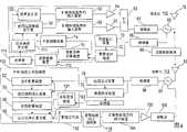
图4是应用外环/加权开环功率控制的两个通信台的组件示意图。Figure 4 is a schematic diagram of the components of two communication stations applying outer loop/weighted open loop power control.
图5是外环/加权开环功率控制系统、加权开环功率控制系统和闭环功率控制系统的性能曲线图。Fig. 5 is a performance graph of an outer loop/weighted open loop power control system, a weighted open loop power control system and a closed loop power control system.
图6是上述三种系统在码组差错率(BLER)方面的性能曲线图。FIG. 6 is a graph showing the performance of the above three systems in terms of Block Error Rate (BLER).
具体实施方式Detailed ways
下面结合附图对优选实施例进行说明,在整个过程中,类同的数字表示类同的元件。外环/加权开环功率控制将用图3的程序框图和图4所示的两个简化了的通信台110,112的组件来说明。在下面的说明中,发射机功率被控制的通信台称为发射台112而接收功率已被控制了的通信的通信台称为接收台110。由于外环/加权开环功率控制可被用于上行链路、下行链路或两种类型兼而有之的通信,功率被控制的发射机可涉及基站301、用户设备321或既涉及基站301又涉及用户设备321。由此,如果上行链路和下行链路的功率控制都被使用的话,则接收和发射台的组件都既涉及基站301又涉及用户设备321。The preferred embodiments will be described below with reference to the accompanying drawings. Throughout the process, similar numbers represent similar components. Outer loop/weighted open loop power control will be illustrated using the block diagram of FIG. 3 and the components of two
在步骤38中,接收台110接收各种射频信号,其中包括由发射台112使用一个天线78或一个天线阵发送的通信。接收到的信号经过一个隔离器66而传输到解调器68,以产生基带信号。该基带信号例如由一个信道估计装置70和一个数据估计装置72在时隙中利用分配给发射台通信的合适的编码进行处理。信道估计装置70通常运用基带信号中的训练序列成分来提供信道信息,例如信道脉冲响应。信道信息被数据估计装置72、干扰测量装置74和发射功率计算装置76使用。数据估计装置72使用信道信息从信道中通过估计软码元来恢复数据。In
在发射台112的通信发射之前,通信中的数据信号通过一个检错/纠错编码器110被进行差错编码。尽管其它类型的差错编码方案也可被使用,但典型的编码方案是后跟前向纠错编码的循环冗余码(CRC)。The data signal in the communication is error coded by an error detection/
利用数据估计装置72产生的软码元,检错装置112检测软码元中的差错。在步骤39中,处理器111分析检测到的差错并确定接收到的通信的差错率。在步骤40中,根据该差错率,处理器111确定在发射台112目标电平需要改变的量(如果有改变的话),例如目标信号与干扰之比(SIRTARGET)的改变量。根据已确定的量,目标调整发生器114产生目标调整信号。在步骤41中,该目标调整信号随后被发送至发射台。目标调整信号通过例如专用信道或基准信道被发送给发射台112。Using the soft symbols generated by the data estimation means 72, the error detection means 112 detects errors in the soft symbols. In
一种确定目标电平调整量的技术使用了上下限的方法。如果被确定的差错率超过了上限,则目标电平处于一个不可接受的低电平而需要被提高。发出一个目标电平调整信号以指示将目标电平增加。如果被确定了的差错率低于下限,则目标电平处于一个不必要的高电平而可被降低。通过降低目标电平,发射台的功率电平就被降低从而减少对其它使用同一时隙和频谱的通信的干扰。为了提高性能,差错率一超过上限,就发出目标调整。结果,高差错率被快速地改善而低差错率被缓慢地调整,例如每10秒一次。如果差错率处于上下限之间,就不发出目标调整量而维持目标电平不变。One technique for determining the amount of target level adjustment uses a method of upper and lower bounds. If the determined error rate exceeds the upper limit, the target level is at an unacceptably low level and needs to be raised. Sends a target level adjust signal to indicate that the target level should be increased. If the determined error rate is below the lower limit, the target level is unnecessarily high and can be lowered. By reducing the target level, the power level of the transmitting station is reduced to reduce interference to other communications using the same time slot and spectrum. To improve performance, target adjustments are issued as soon as the error rate exceeds an upper bound. As a result, high error rates are quickly corrected and low error rates are adjusted slowly, for example every 10 seconds. If the error rate is between the upper and lower limits, no target adjustment is issued and the target level remains unchanged.
下面说明的是将上述技术应用于一个使用循环冗余码(CRC)和前向纠错(FEC)编码的系统。每个循环冗余码(CRC)码组都被用于检验差错。每当确定一帧有一个差错时,就递增计数器。一旦计数器的数超过了上限,例如1.5到2倍于所要求的码组差错率(BLER)时,目标调整就被发送以提高目标电平。为了调整发射台112的目标信号干扰比(SIRTARGET),SIRTARGET的增加量(SIRINC)就被发送,其值典型地在0.25dB至4dB的范围内。如果累计的CRC的帧数超过了一个预定的限度,例如1000码组,计数器的值就与前述的下限相比较,该下限的值例如可以是所要求的BLER的0.2到0.6倍。如果累计的码组差错数低于前述下限,就发送一个用以降低目标电平的目标调整信号SIRDEC,其典型的范围是0.25dB至4dB。SIRDEC的值可基于SIRINC和目标码组差错率BLERTARGET而定。BLERTARGET基于业务的类型而定,其典型的范围是0.1%至10%。等式1说明了确定SIRDEC的这种方法。Described below is the application of the above techniques to a system using cyclic redundancy code (CRC) and forward error correction (FEC) coding. Each cyclic redundancy code (CRC) block is used to check for errors. The counter is incremented each time a frame is determined to have an error. Once the number of counters exceeds an upper limit, eg 1.5 to 2 times the required block error rate (BLER), a target adjustment is sent to increase the target level. In order to adjust the target signal-to-interference ratio (SIRTARGET ) of the transmitting
SIRDEC=SIRINC×BLERTARGET/(1-BLERTARGET) 等式1SIRDEC = SIRINC × BLERTARGET / (1-BLERTARGET ) Equation 1
如果计数器中的数处于预定的码组上下限之间,则不发送目标调整信号。If the number in the counter is between the predetermined upper and lower limits of the block, no target adjustment signal is sent.
另一方面,也可用单个的门限。如果差错率超过该门限,目标电平就被提高。如果差错率低于该门限,目标电平就被降低。另外,目标电平调整信号可有几个调整等级,例如,根据所确定的差错率与所要求的差错率之间的差,目标电平调整信号的值可在0dB至±4dB之间,以0.25dB为递增量。Alternatively, a single threshold can also be used. If the error rate exceeds this threshold, the target level is increased. If the error rate is below this threshold, the target level is lowered. In addition, the target level adjustment signal can have several adjustment levels, for example, according to the difference between the determined error rate and the required error rate, the value of the target level adjustment signal can be between 0dB to ±4dB, in order 0.25dB is the increment.
接收台110的干扰测量装置74确定信道里以分贝为单位的干扰水平IRS,这种确定或基于信道信息,或基于由数据估计装置72所产生的软码元,或两者兼而有之。利用软码元和信道信息,发射功率计算装置76通过控制放大器54的增益来控制接收台的发射功率电平。The interference measuring means 74 of the receiving
在步骤41中,接收台110向发射台112发送一个通信,用于估计接收台110和发射台112之间的路径损耗。该通信可通过诸多信道中的任意一个发送。在时分双工系统中,用于估计路径损耗的信道一般被称为基准信道,尽管其它的信道也可被用于估计路径损耗。如果接收台110是一个基站301,则优选为该通信通过下行链路公共信道或一个公共控制物理信道(CCPCH)来发送。通过基准信道被传输至发射台112的数据称为基准信道数据。该基准信道数据如所示那样可包括干扰水平IRS,该干扰水平IRS与其他基准数据,例如发射功率电平TRS,一起被多路传输。干扰水平IRS与基准信道功率电平TRS可被其他信道发送,例如信号信道。In
基准信道数据由基准信道数据发生器56产生。根据通信的带宽要求,基准数据被分配一个或多个资源单元。一个扩频(spread)和训练序列插入装置58将基准信道数据扩频并使基准数据与合适的时隙内的训练序列及分配的资源单元的代码一起被时分复用。作为结果的序列称为通信脉冲串。随后,该通信脉冲串被一个放大器60放大。一个加法器62将该被放大了的通信脉冲串与通过其它装置如数据发生器50、扩频和训练序列插入装置52和放大器54所产生的通信脉冲串相加。The reference channel data is generated by a reference
相加后的通信脉冲串被一个调制器64调制。被调制的信号如所示那样经过一个隔离器66后被一个天线78发射,或通过一个天线阵发射。该被发射的信号经过一个无线射频信道80到达发射台112的天线82。用于发射通信的调制的类型可以是熟悉此技术的人员所知的任何一种,例如直接相移键控(DPSK)或四相移相键控(QPSK)。The added communication burst is modulated by a
发射台112的天线82或天线阵接收各种射频信号,其中包括目标调整信号。接收到的信号经过一个隔离器84传送至一个解调器86以产生基带信号。该基带信号例如被一个信道估计装置88和一个数据估计装置90在该系列时隙中与被分配给接收台110的通信脉冲串的合适的代码一起处理。信道估计装置88通常利用基带信号中的训练序列成分来提供信道信息,例如信道脉冲响应。信道信息由数据估计装置90和功率测量装置92使用。The
在步骤42中,对应于基准信道的经过处理的通信的功率电平RTS被功率测量装置92测量,然后被发送到一个路径损耗估计装置94。信道估计装置88和数据估计装置90都能够将基准信道与其它信道分开。如果一个自动增益控制装置或放大器被用于处理所接收到的信号,则测得的功率电平就或在功率测量装置92或在路径损耗估计装置94被调整以矫正自动增益控制装置或放大器的增益。功率测量装置是外环/加权开环控制装置100的一个组件。如图4所示,外环/加权开环控制装置100包括功率测量装置92、路径损耗估计装置94、质量测量装置96、目标更新装置101和发射功率计算装置98。In
为了确定路径损耗L,发射台112也要求通信的发射功率电平TRS。通信的发射功率电平TRS可与通信数据一起被发送,或由信号信道发送。如果发射功率电平TRS与通信数据一起被发送,则数据估计装置90翻译功率电平并将翻译后的功率电平传送给路径估计装置94。如果接收台110是一个基站301,那么发射功率电平TRS最好经由来自基站301的广播信道传送。在步骤43中,通过从发送的通信的发射功率电平TRS减去接收的通信的功率电平RTS,路径损耗估计装置94估计两个通信台110,112之间的路径损耗L。另外,在步骤44中,路径损耗的长期估计L0被更新。长期路径损耗估计的一例是长期平均值。路径损耗的长期平均值L0是路径损耗估计的平均值。在某些情况下,接收台110可以发射一个发射功率电平基准而非发射功率电平TRS。这样,路径损耗估计装置94为路径损耗L提供基准电平。In order to determine the path loss L, the transmitting
由于时分双工系统在相同的频谱内发射下行链路和上行链路通信,这些通信所经历的情况是相似的。这种现象称为互易(reciprocity)。由于互易,下行链路所经历的路径损耗也将由上行链路所经历,反过来也一样。通过给目标电平施加一个估计的路径损耗,由发射台112向接收台110发送的通信的发射功率电平就被确定了。Since time division duplex systems transmit downlink and uplink communications within the same frequency spectrum, the conditions experienced by these communications are similar. This phenomenon is called reciprocity. Due to reciprocity, the path loss experienced by the downlink will also be experienced by the uplink and vice versa. By applying an estimated path loss to the target level, the transmit power level for communications sent by transmitting
如果在估计的路径损耗与发射的通信之间存在一个时延,发射的通信所受到的路径损耗可能与计算得到的路径损耗有差别。在时分双工系统中,如果通信在不同的时隙361-36n被发送,接收的和发送的通信间的时延会降低开环功率控制系统的性能。在步骤45中,为了克服这些缺点,加权开环功率控制系统利用一个质量测量装置96来确定估计得到的路径损耗的质量,并相应地对估计得到的路径损耗L和路径损耗的长期平均值L0加权。If there is a delay between the estimated path loss and the transmitted communication, the path loss experienced by the transmitted communication may differ from the calculated path loss. In a time division duplex system, if communications are sent in different time slots361-36n , thedelay between the received and transmitted communications can degrade the performance of the open loop power control system. In
为了进一步增强外环/加权开环的性能,目标电平就被调整。处理器103将数据估计装置90产生的软码元转换成比特并提取出目标调整信息,例如SIRTARGET调整。在步骤46中,目标更新装置101利用目标调整,来调整目标电平。目标电平可以是在接收台110的SIRTARGET或目标接收功率电平。To further enhance the performance of the outer loop/weighted open loop, the target level is adjusted. The
在步骤47中,发射功率计算装置98将调整的目标电平与加权了的路径损耗估计值L和路径损耗估计值的长期平均值L0结合来确定发射台的发射功率电平。In
来自发射台112的通信中所要发射的数据产生于数据发生器102。该数据被差错检测/纠正编码器110进行差错检测/纠正编码。差错编码数据被扩频,并且是在合适的时隙与训练序列插入装置104产生的一个训练序列、和被分配给的资源单元的代码一起进行时分复用,由此产生一个通信脉冲串。扩频信号被一个放大器106放大并被一个调制器108调制至射频。放大器的增益由发射功率计算装置98控制以达到被确定了的发射功率电平。功率被控制的通信脉冲串通过隔离器84,然后被天线82发射。Data to be transmitted in communications from
下面是一个外环/加权开环功率控制的算法。以分贝为单位的发射台的发射功率电平PTS用等式2确定。The following is an algorithm for outer loop/weighted open loop power control. The transmit power level PTS of the transmitting station in decibels is determined using Equation 2.
PTS=SIRTARGET+IRS+α(L-L0)+L0+CONSTANT VALUE 等式2PTS =SIRTARGET +IRS +α(LL0 )+L0 +CONSTANT VALUE Equation 2
SIRTARGET具有根据接收到的目标调整信号的调整值。对于下行链路来说,SIRTARGET的初始值在发射台112是已知的。对于上行链路的功率控制来说,SIRTARGET由接收台110传输至发射台112。另外,还可以传送经调整的SIRTARGET的最大值和最小值。经调整的SIRTARGET的值限制在最大值和最小值之间。IRS是接收台110的干扰功率电平的测量值。SIRTARGET has an adjustment value based on the received target adjustment signal. For the downlink, the initial value of SIRTARGET is known at the transmitting
L是路径损耗被估计的最近时隙361-36n的以分贝为单位的路径损耗估计值,即TRS-RTS。L0是以分贝为单位的路径损耗的长期平均值,是路径损耗的估计值L的动态平均值。CONSTANT VALUE是一个矫正项。CONSTANT VALUE矫正上行链路和下行链路信道之间的差异,例如补偿上行链路和下行链路之间增益的差异。另外,如果接收台的发射功率基准电平被发送以替代实际的发射功率TRS,则CONSTANT VALUE可以提供校正。如果接收台110是一个基站,则CONSTANT VALUE最好通过一个Layer 3消息来发送。L is the path loss estimate in decibels for the nearest time slot 361 - 36n for which the path loss is estimated, ie TRS - RTS .L0 is the long-term average value of the path loss in decibels, and is the dynamic average value of the estimated value L of the path loss. CONSTANT VALUE is a correction term. CONSTANT VALUE corrects for differences between uplink and downlink channels, eg compensates for differences in gain between uplink and downlink. Additionally, CONSTANT VALUE may provide corrections if the receiving station's transmit power reference level is sent instead of the actual transmit power TRS . If the receiving
加权值α是所估计路径损耗的质量量度,最好根据由发射台112发出的通信中最终的路径损耗估计时隙n和最初的时隙之间的时隙361-36n的数目n来确定。α的值在0和1之间。一般地,如果时隙之间的时差小,则最近的路径损耗估计值将会是相当精确的,α的值接近1。反之,如果时差大,则路径损耗估计值可能不精确,路径损耗测量值的长期平均值很可能是路径损耗的更好的估计。相应地,α设为更接近1的值。The weighting value α is a measure of the quality of the estimated path loss, preferably based on the number n of slots 361 - 36n between the final path loss estimate slot n and the initial slot in the communication sent by the transmitting
等式3和4是确定α值的等式。Equations 3 and 4 are equations for determining the value of α.
α=1-(D-1)/(Dmax-1) 等式3α=1-(D-1)/(Dmax -1) Equation 3
α=max{1-(D-1)/(Dmax-allowed-1),0} 等式4α=max{1-(D-1)/(Dmax-allowed -1),0} Equation 4
D是时隙361-36n中处于发射的通信中最终的路径损耗估计时隙和最初的路径损耗估计时隙之间的时隙的数目,其被称为时隙延迟。如果该延迟是一个时隙,α就是1。Dmax是最大的可能延迟,对于具有15个时隙的一帧来说,其典型值为7。如果延迟为Dmax,则α就为0。Dmax-allowed是利用开环功率控制所允许的时隙延迟的最大值。如果延迟超过了Dmax-allowed,则开环功率控制就通过将α设为0而有效地关闭。发射通信的发射功率由发射功率计算装置98所确定的发射功率电平PTS来设置。D is the number of slots in slots 36i-36n between the final path loss estimate slot and the initial path loss estimate slot in the transmitted communication, which is called the slot delay. If the delay is one slot, α is 1.Dmax is the maximum possible delay, with a typical value of 7 for a frame with 15 slots. If the delay is Dmax , then α is zero. Dmax-allowed is the maximum value of slot delay allowed by open-loop power control. If the delay exceeds Dmax-allowed , the open loop power control is effectively turned off by setting α to zero. The transmission power for transmitting communications is set by the transmission power level PTS determined by the transmission power calculation means 98 .
图5和图6比较了加权外环/开环、开环和闭环系统的性能。图5和图6中的仿真与外环/加权开环模型的算法稍有不同。在这种模型中,每个码组的目标SIR都被更新。如果检测到一个码组差错,就增加SIRTARGET;如果没有检测到码组差错,就减少SIRTARGET。外环/加权开环系统使用等式2。等式3用于计算α。上述仿真比较了上述系统在控制一个用户设备321的发射功率电平时的性能。为进行仿真,每个码组被填充16比特循环冗余码,每个码组是四帧。当一个码组中发生至少两个原始比特的差错时,就声明一个码组差错。对上行链路的通信信道,每帧分配一个时隙。码组差错率的目标是10%。每4帧就更新SIRTARGET。上述仿真说明这些系统对于一个每小时移动30公里的用户设备UE321的性能。被仿真的基站使用两个天线分集用于接收,每个天线有一个三指RAKE接收器。该仿真近似于一个真实的信道,SIR估计基于加性高斯白噪声(AWGN)中的1型脉冲串段的中间段(midamble)序列。该仿真使用国际电信联盟(ITU)普通B型信道和四相移相键控(QPSK)调制。干扰电平假定为没有不确定性。信道编码方案没有被考虑。L0设为0dB。Figures 5 and 6 compare the performance of weighted outer-loop/open-loop, open-loop, and closed-loop systems. The simulations in Figures 5 and 6 differ slightly from the algorithm for the outer-loop/weighted-open-loop model. In this model, the target SIR is updated for each code group. If a block error is detected, SIRTARGET is increased; if no block error is detected, SIRTARGET is decreased. The outer loop/weighted open loop system uses Equation 2. Equation 3 is used to calculate α. The above simulation compares the performance of the above system when controlling the transmission power level of one user equipment321 . For simulation, each code group is filled with a 16-bit cyclic redundancy code, and each code group is four frames. A block error is declared when an error of at least two original bits occurs in a block. For uplink communication channels, one time slot is allocated per frame. The target for block error rate is 10%. SIRTARGET is updated every 4 frames. The above simulations illustrate the performance of these systems for a user equipmentUE321 moving 30 kilometers per hour. The simulated base station uses two antenna diversity for reception, each antenna has a three-finger RAKE receiver. The simulation approximates a real channel and the SIR estimation is based on the midamble sequence of type 1 burst segments in additive white Gaussian noise (AWGN). The simulation uses an International Telecommunication Union (ITU) generic B-type channel and Quadrature Phase Shift Keying (QPSK) modulation. Interference levels are assumed to have no uncertainty. Channel coding schemes are not considered. L0 is set to 0dB.
图5中的图线120示出了在对于10-1的BLER所要求的ES/No作为上行链路时隙和最近的下行链路时隙之间的时延函数的情况下,所期望的性能。延迟由时隙的数目来表达。ES是复合码元的能量。图5说明:当增益/干扰的不确定性被忽略时,该组合系统的性能就几乎等于加权开环系统。该组合系统对于所有的延迟在性能上都胜过了闭环系统。Graph 120 in Fig. 5 shows that in the case of the required ES /No for a BLER of 10−1 as a function of the time delay between the uplink slot and the nearest downlink slot, the expected performance. The delay is expressed by the number of slots.ES is the energy of the composite symbol. Figure 5 shows that when the uncertainty of gain/interference is ignored, the performance of the combined system is almost equal to the weighted open-loop system. The combined system outperforms the closed-loop system for all delays.
在存在增益和干扰的不确定性的情况下,开环系统的发射功率电平相对于标称值来说,或是太高或是太低。在图6中的图线122中,使用了-2dB的增益不确定性。图6示出BLER作为延迟的函数。为了得到一个10-1的BLER,每个系统的初始基准SIRTARGET被设为由图5中得到的其相应的标称值。图6说明,在存在增益不确定性的情况下,组合系统和闭环系统都获得了所要求的BLER。加权开环系统的性能严重地下降了。In the presence of uncertainties in gain and interference, open-loop systems transmit power levels that are either too high or too low relative to nominal values. In plot 122 in Figure 6, a gain uncertainty of -2dB is used. Figure 6 shows BLER as a function of delay. In order to obtain a BLER of 10−1 , the initial reference SIRTARGET of each system is set to its corresponding nominal value obtained from Fig. 5 . Figure 6 illustrates that both the combined system and the closed-loop system achieve the required BLER in the presence of gain uncertainty. The performance of weighted open-loop systems is severely degraded.
Claims (9)
Translated fromChineseApplications Claiming Priority (6)
| Application Number | Priority Date | Filing Date | Title |
|---|---|---|---|
| US12541799P | 1999-03-22 | 1999-03-22 | |
| US60/125,417 | 1999-03-22 | ||
| US13655799P | 1999-05-28 | 1999-05-28 | |
| US13655699P | 1999-05-28 | 1999-05-28 | |
| US60/136,556 | 1999-05-28 | ||
| US60/136,557 | 1999-05-28 |
Related Parent Applications (1)
| Application Number | Title | Priority Date | Filing Date |
|---|---|---|---|
| CNB008052409ADivisionCN1161891C (en) | 1999-03-22 | 2000-03-22 | Outer loop/weighted open loop power control in a time division duplex communication system |
Related Child Applications (3)
| Application Number | Title | Priority Date | Filing Date |
|---|---|---|---|
| CN200610095730XADivisionCN101094017B (en) | 1999-03-22 | 2000-03-22 | Combined closed loop/open loop power control in a time division duplex communication system |
| CN200610095732.9ADivisionCN101094018B (en) | 1999-03-22 | 2000-03-22 | Combined closed loop/open loop power control in a time division duplex communication system |
| CN200610095731.4ADivisionCN1878017B (en) | 1999-03-22 | 2000-03-22 | Combined closed loop/open loop power in tdd communication systems controls |
Publications (2)
| Publication Number | Publication Date |
|---|---|
| CN1551528Atrue CN1551528A (en) | 2004-12-01 |
| CN100362768C CN100362768C (en) | 2008-01-16 |
Family
ID=27383242
Family Applications (12)
| Application Number | Title | Priority Date | Filing Date |
|---|---|---|---|
| CN2006100958942AExpired - Fee RelatedCN1953346B (en) | 1999-03-22 | 2000-03-22 | Weighted open loop power control in a time division duplex communication system |
| CNB008049645AExpired - Fee RelatedCN1148014C (en) | 1999-03-22 | 2000-03-22 | Combined closed loop/open loop power control in a time division duplex communication system |
| CN2006100958957AExpired - Fee RelatedCN1956345B (en) | 1999-03-22 | 2000-03-22 | Weighted open loop power control method in a time division duplex communication system |
| CNB2004100431028AExpired - Fee RelatedCN100449957C (en) | 1999-03-22 | 2000-03-22 | Weighted open loop power control in time division multiplexed communication systems |
| CNB008052417AExpired - Fee RelatedCN1157862C (en) | 1999-03-22 | 2000-03-22 | Weighted open loop power control in time division multiplexed communication systems |
| CN2006100958938AExpired - Fee RelatedCN1956344B (en) | 1999-03-22 | 2000-03-22 | Weighted open loop power control in a time division duplex communication system |
| CNB200410059280XAExpired - Fee RelatedCN100362768C (en) | 1999-03-22 | 2000-03-22 | Outer Loop/Weighted Open Loop Power Control in Time Division Duplex Communication Systems |
| CN200610095731.4AExpired - Fee RelatedCN1878017B (en) | 1999-03-22 | 2000-03-22 | Combined closed loop/open loop power in tdd communication systems controls |
| CNB2004100078619AExpired - Fee RelatedCN1322683C (en) | 1999-03-22 | 2000-03-22 | Outer loop/weighted open loop power control in time division duplex communication system |
| CN200610095730XAExpired - Fee RelatedCN101094017B (en) | 1999-03-22 | 2000-03-22 | Combined closed loop/open loop power control in a time division duplex communication system |
| CNB008052409AExpired - Fee RelatedCN1161891C (en) | 1999-03-22 | 2000-03-22 | Outer loop/weighted open loop power control in a time division duplex communication system |
| CN200610095732.9AExpired - Fee RelatedCN101094018B (en) | 1999-03-22 | 2000-03-22 | Combined closed loop/open loop power control in a time division duplex communication system |
Family Applications Before (6)
| Application Number | Title | Priority Date | Filing Date |
|---|---|---|---|
| CN2006100958942AExpired - Fee RelatedCN1953346B (en) | 1999-03-22 | 2000-03-22 | Weighted open loop power control in a time division duplex communication system |
| CNB008049645AExpired - Fee RelatedCN1148014C (en) | 1999-03-22 | 2000-03-22 | Combined closed loop/open loop power control in a time division duplex communication system |
| CN2006100958957AExpired - Fee RelatedCN1956345B (en) | 1999-03-22 | 2000-03-22 | Weighted open loop power control method in a time division duplex communication system |
| CNB2004100431028AExpired - Fee RelatedCN100449957C (en) | 1999-03-22 | 2000-03-22 | Weighted open loop power control in time division multiplexed communication systems |
| CNB008052417AExpired - Fee RelatedCN1157862C (en) | 1999-03-22 | 2000-03-22 | Weighted open loop power control in time division multiplexed communication systems |
| CN2006100958938AExpired - Fee RelatedCN1956344B (en) | 1999-03-22 | 2000-03-22 | Weighted open loop power control in a time division duplex communication system |
Family Applications After (5)
| Application Number | Title | Priority Date | Filing Date |
|---|---|---|---|
| CN200610095731.4AExpired - Fee RelatedCN1878017B (en) | 1999-03-22 | 2000-03-22 | Combined closed loop/open loop power in tdd communication systems controls |
| CNB2004100078619AExpired - Fee RelatedCN1322683C (en) | 1999-03-22 | 2000-03-22 | Outer loop/weighted open loop power control in time division duplex communication system |
| CN200610095730XAExpired - Fee RelatedCN101094017B (en) | 1999-03-22 | 2000-03-22 | Combined closed loop/open loop power control in a time division duplex communication system |
| CNB008052409AExpired - Fee RelatedCN1161891C (en) | 1999-03-22 | 2000-03-22 | Outer loop/weighted open loop power control in a time division duplex communication system |
| CN200610095732.9AExpired - Fee RelatedCN101094018B (en) | 1999-03-22 | 2000-03-22 | Combined closed loop/open loop power control in a time division duplex communication system |
Country Status (19)
| Country | Link |
|---|---|
| EP (11) | EP1367740B1 (en) |
| JP (3) | JP3621886B2 (en) |
| KR (2) | KR100401217B1 (en) |
| CN (12) | CN1953346B (en) |
| AT (10) | ATE412279T1 (en) |
| AU (3) | AU761541B2 (en) |
| BR (2) | BR0009233A (en) |
| CA (5) | CA2367353C (en) |
| DE (11) | DE60006945T2 (en) |
| DK (7) | DK1349294T3 (en) |
| ES (9) | ES2211522T3 (en) |
| HK (3) | HK1041575B (en) |
| ID (2) | ID30329A (en) |
| IL (7) | IL145026A0 (en) |
| MY (2) | MY129851A (en) |
| NO (4) | NO323601B1 (en) |
| SG (9) | SG112830A1 (en) |
| TW (3) | TW498645B (en) |
| WO (3) | WO2000057575A1 (en) |
Cited By (4)
| Publication number | Priority date | Publication date | Assignee | Title |
|---|---|---|---|---|
| CN101180804B (en)* | 2005-04-20 | 2011-06-08 | 三菱电机株式会社 | Communication quality judgment method, mobile station, base station and communication system |
| CN101512925B (en)* | 2006-09-08 | 2013-03-13 | 高通股份有限公司 | Serving sector interference broadcast and corresponding reverse link traffic power control |
| CN105722202A (en)* | 2005-03-15 | 2016-06-29 | 高通股份有限公司 | Method And Equipment By Using Interference Information From Multiple Sectors For Power Control |
| CN108809825A (en)* | 2017-04-21 | 2018-11-13 | 联发科技股份有限公司 | Method for establishing bidirectional route and computer readable storage medium |
Families Citing this family (54)
| Publication number | Priority date | Publication date | Assignee | Title |
|---|---|---|---|---|
| US6748234B1 (en)* | 2000-11-21 | 2004-06-08 | Qualcomm Incorporated | Method and apparatus for power control in a wireless communication system |
| JP3440076B2 (en)* | 2000-11-29 | 2003-08-25 | 松下電器産業株式会社 | Wireless infrastructure equipment |
| US6978151B2 (en)* | 2001-05-10 | 2005-12-20 | Koninklijke Philips Electronics N.V. | Updating path loss estimation for power control and link adaptation in IEEE 802.11h WLAN |
| AU2002332038A1 (en)* | 2001-10-09 | 2003-04-22 | Interdigital Technology Corporation | Pathloss aided closed loop power control |
| GB2381417A (en)* | 2001-10-24 | 2003-04-30 | Ipwireless Inc | Transmission power control based on path loss |
| ES2348205T3 (en)* | 2001-11-08 | 2010-12-01 | Telefonaktiebolaget L M Ericsson Ab (Publ) | METHOD FOR LINK ADAPTATION AND CONTROL OF TRANSMISSION POWER. |
| US7133689B2 (en)* | 2002-09-12 | 2006-11-07 | Interdigital Technology Corporation | Method and system for adjusting downlink outer loop power to control target SIR |
| US7372898B2 (en)* | 2002-12-11 | 2008-05-13 | Interdigital Technology Corporation | Path loss measurements in wireless communications |
| CN100568769C (en)* | 2003-06-16 | 2009-12-09 | 株式会社Ntt都科摩 | Control device and wireless control method |
| CN1322767C (en)* | 2003-07-29 | 2007-06-20 | 大唐移动通信设备有限公司 | Power control method for mobile communication system |
| US7403780B2 (en) | 2004-02-19 | 2008-07-22 | Rockwell Collins, Inc. | Hybrid open/closed loop filtering for link quality estimation |
| EP1719301A1 (en)* | 2004-02-19 | 2006-11-08 | Rockwell Collins Inc. | Link adaption for mobile ad hoc and mesh networks |
| CN1973447B (en) | 2004-07-01 | 2012-01-18 | 艾利森电话股份有限公司 | Power control in a communication network and method |
| US7907910B2 (en)* | 2004-08-02 | 2011-03-15 | Intel Corporation | Method and apparatus to vary power level of training signal |
| JP2006050498A (en) | 2004-08-09 | 2006-02-16 | Nec Corp | Mobile communication terminal device, mobile communication method, and program thereof |
| US8897828B2 (en)* | 2004-08-12 | 2014-11-25 | Intellectual Ventures Holding 81 Llc | Power control in a wireless communication system |
| KR100725773B1 (en)* | 2004-08-20 | 2007-06-08 | 삼성전자주식회사 | Apparatus and method for adaptively changing uplink power control scheme according to terminal state in time division duplex mobile communication system |
| US7668564B2 (en)* | 2005-06-20 | 2010-02-23 | Texas Instruments Incorporated | Slow uplink power control |
| CN100385822C (en)* | 2005-11-25 | 2008-04-30 | 凯明信息科技股份有限公司 | Discontinuous transmitting state power control method in TD-SCDMA system |
| KR20070059666A (en)* | 2005-12-07 | 2007-06-12 | 삼성전자주식회사 | Method and apparatus for controlling power in time division duplex communication system |
| CN1988407B (en)* | 2005-12-22 | 2010-07-07 | 大唐移动通信设备有限公司 | Open ring power control method for base station and its physical random cut-in channel |
| CN101064538B (en)* | 2006-04-30 | 2011-04-20 | 中兴通讯股份有限公司 | Power control method for time-division synchronous CDMA communication system |
| CN101119145B (en)* | 2006-08-03 | 2010-10-27 | 普天信息技术研究院 | Open-loop Power Control Method of Auxiliary Frequency Point in Time Division-Synchronous Code Division Multiple Access System |
| CN107105489A (en)* | 2006-10-03 | 2017-08-29 | 交互数字技术公司 | Combined type open/close for E UTRA interference mitigation(Based on CQI)Up-link transmission power is controlled |
| KR101163280B1 (en) | 2006-10-03 | 2012-07-10 | 인터디지탈 테크날러지 코포레이션 | Combined open loop/closed loop cqi-based uplink transmit power control with interference mitigation for e-utra |
| US8509836B2 (en) | 2007-03-07 | 2013-08-13 | Interdigital Technology Corporation | Combined open loop/closed loop method for controlling uplink power of a mobile station |
| CN101296003B (en)* | 2007-04-25 | 2012-11-28 | 中兴通讯股份有限公司 | Power control method and system for reinforced uplink transmitting scheduling information |
| CN101340215B (en)* | 2007-07-04 | 2012-07-25 | 鼎桥通信技术有限公司 | Method and device for determining transmitting power of special burst sub-frame |
| CN101345906B (en)* | 2007-07-13 | 2012-03-14 | 电信科学技术研究院 | Wireless resource allocation method and apparatus of high speed grouping access system |
| CN101394206B (en)* | 2007-09-17 | 2012-11-28 | 中兴通讯股份有限公司 | Method for downlink power control synchronous signaling transmission |
| DE602007008102D1 (en)* | 2007-09-28 | 2010-09-09 | Ntt Docomo Inc | Decentralized C / I power control for TDD |
| US8958460B2 (en) | 2008-03-18 | 2015-02-17 | On-Ramp Wireless, Inc. | Forward error correction media access control system |
| CN101568173B (en)* | 2008-04-21 | 2012-02-01 | 电信科学技术研究院 | Method, device and system for controlling power |
| BRPI0822996A2 (en) | 2008-09-03 | 2015-06-23 | Thomson Licensing | Method and apparatus for wireless transmission power control |
| US8363699B2 (en) | 2009-03-20 | 2013-01-29 | On-Ramp Wireless, Inc. | Random timing offset determination |
| US7702290B1 (en)* | 2009-04-08 | 2010-04-20 | On-Ramp Wirless, Inc. | Dynamic energy control |
| CN101577958B (en)* | 2009-06-02 | 2010-11-03 | 北京天碁科技有限公司 | System and method for testing performance of closed loop power control algorithm |
| US9031599B2 (en) | 2009-12-08 | 2015-05-12 | Futurewei Technologies, Inc. | System and method for power control |
| US8311055B2 (en) | 2009-12-08 | 2012-11-13 | Futurewei Technologies, Inc. | System and method for scheduling users on a wireless network |
| US8515474B2 (en) | 2010-01-20 | 2013-08-20 | Futurewei Technologies, Inc. | System and method for scheduling users on a wireless network |
| US8437794B2 (en)* | 2010-01-28 | 2013-05-07 | Alcatel Lucent | Methods of determining uplink target signal-to-interfence-and-noise ratios and systems thereof |
| US20110263212A1 (en)* | 2010-04-26 | 2011-10-27 | Chih-Hao Yeh | Wireless device and controlling method of wireless device |
| TWI488527B (en)* | 2010-05-05 | 2015-06-11 | Zyxel Communications Corp | Communication method utilized in time division multiple access system, related mobile device and base station |
| CN104247534A (en) | 2012-01-19 | 2014-12-24 | 华为技术有限公司 | System and method for uplink resource allocation |
| EP2868878B1 (en) | 2012-07-04 | 2017-06-21 | Aisin Seiki Kabushiki Kaisha | Oil separator |
| CN104244390A (en)* | 2013-06-17 | 2014-12-24 | 中兴通讯股份有限公司 | Open loop joint power control method and device of wireless body area network |
| US20170141860A1 (en)* | 2014-06-25 | 2017-05-18 | Nec Corporation | Wireless relay system, wireless relay method, storage medium in which wireless relay program is stored, and wireless relay station |
| CN108235420B (en)* | 2016-12-12 | 2021-06-25 | 上海朗帛通信技术有限公司 | Method and device for power adjustment in UE and base station |
| CN106973431B (en)* | 2017-02-14 | 2021-03-05 | 深圳市金立通信设备有限公司 | Transmission power adjusting method and terminal |
| CN110115068B (en)* | 2017-04-21 | 2023-05-02 | 深圳市大疆创新科技有限公司 | Adaptive transmit power control for wireless communication systems |
| CN116209039A (en) | 2018-03-12 | 2023-06-02 | 苹果公司 | Apparatus, system and method for scheduling power profiles for UE power saving |
| US11589305B2 (en)* | 2018-03-12 | 2023-02-21 | Apple Inc. | Scheduling profile for UE power savings |
| CN111542104A (en)* | 2020-04-20 | 2020-08-14 | 东南大学 | A closed-loop power control method applied to inter-device communication |
| CN112910430B (en)* | 2021-01-15 | 2024-03-12 | 北京格润海泰科技有限公司 | Control method and device for automatically adjusting power gain of radio frequency signal |
Family Cites Families (26)
| Publication number | Priority date | Publication date | Assignee | Title |
|---|---|---|---|---|
| US4868795A (en)* | 1985-08-05 | 1989-09-19 | Terra Marine Engineering, Inc. | Power leveling telemetry system |
| US4947459A (en)* | 1988-11-25 | 1990-08-07 | Honeywell, Inc. | Fiber optic link noise measurement and optimization system |
| US5056109A (en) | 1989-11-07 | 1991-10-08 | Qualcomm, Inc. | Method and apparatus for controlling transmission power in a cdma cellular mobile telephone system |
| SE467332B (en)* | 1990-06-21 | 1992-06-29 | Ericsson Telefon Ab L M | PROCEDURE FOR POWER CONTROL IN A DIGITAL MOBILE PHONE SYSTEM |
| EP0569688A1 (en)* | 1992-04-29 | 1993-11-18 | Hagenuk Telecom GmbH | Method and apparatus for fading compensation for TDMA-receivers |
| US5590173A (en)* | 1992-08-05 | 1996-12-31 | Beasley; Andrew S. | Delay insensitive base station-to-handset interface for radio telephone systems |
| NZ255617A (en)* | 1992-09-04 | 1996-11-26 | Ericsson Telefon Ab L M | Tdma digital radio: measuring path loss and setting transmission power accordingly |
| US5333175A (en)* | 1993-01-28 | 1994-07-26 | Bell Communications Research, Inc. | Method and apparatus for dynamic power control in TDMA portable radio systems |
| FI96554C (en)* | 1993-02-05 | 1996-07-10 | Nokia Mobile Phones Ltd | Time multiplexed cellular radio telephone system and radio telephone for it |
| DE59408295D1 (en)* | 1993-03-19 | 1999-07-01 | Siemens Ag | Method for regulating the transmission power of a mobile station in a cellular mobile radio network |
| JPH0774727A (en)* | 1993-09-06 | 1995-03-17 | Matsushita Electric Ind Co Ltd | Transmission power control method for spread spectrum communication |
| US6088590A (en)* | 1993-11-01 | 2000-07-11 | Omnipoint Corporation | Method and system for mobile controlled handoff and link maintenance in spread spectrum communication |
| JP2974274B2 (en)* | 1994-05-12 | 1999-11-10 | エヌ・ティ・ティ移動通信網株式会社 | Transmission power control method and transmission power control device |
| JP3386586B2 (en)* | 1994-08-18 | 2003-03-17 | 松下電器産業株式会社 | Mobile communication method |
| WO1996031009A1 (en)* | 1995-03-27 | 1996-10-03 | Celsat America, Inc. | Cellular communications power control system |
| ZA965340B (en)* | 1995-06-30 | 1997-01-27 | Interdigital Tech Corp | Code division multiple access (cdma) communication system |
| US5629934A (en)* | 1995-06-30 | 1997-05-13 | Motorola, Inc. | Power control for CDMA communication systems |
| WO1997008847A1 (en)* | 1995-08-31 | 1997-03-06 | Nokia Telecommunications Oy | Method and device for controlling transmission power of a radio transmitter in a cellular communication system |
| FI103555B1 (en)* | 1996-06-17 | 1999-07-15 | Nokia Mobile Phones Ltd | Checking the transmit power in wireless packet data transmission |
| WO1997050197A1 (en)* | 1996-06-27 | 1997-12-31 | Ntt Mobile Communications Network Inc. | Transmitted power controller |
| KR980007105A (en)* | 1996-06-28 | 1998-03-30 | 김광호 | Method for controlling transmission power of mobile station |
| JP3240262B2 (en)* | 1996-07-25 | 2001-12-17 | 株式会社日立国際電気 | Adaptive modulation transmission method and system |
| US5859838A (en)* | 1996-07-30 | 1999-01-12 | Qualcomm Incorporated | Load monitoring and management in a CDMA wireless communication system |
| US6829226B1 (en)* | 1997-04-04 | 2004-12-07 | Ericsson Inc. | Power control for a mobile terminal in a satellite communication system |
| WO1999007105A2 (en)* | 1997-08-01 | 1999-02-11 | Salbu Research And Development (Proprietary) Limited | Power adaptation in a multi-station network |
| JPH11275035A (en)* | 1998-01-26 | 1999-10-08 | Matsushita Electric Ind Co Ltd | Mobile station communication device, base station communication device, and wireless communication system |
- 2000
- 2000-03-21MYMYPI20001119Apatent/MY129851A/enunknown
- 2000-03-21MYMYPI20001120Apatent/MY128631A/enunknown
- 2000-03-22ATAT05103710Tpatent/ATE412279T1/ennot_activeIP Right Cessation
- 2000-03-22JPJP2000607350Apatent/JP3621886B2/ennot_activeExpired - Fee Related
- 2000-03-22BRBR0009233-9Apatent/BR0009233A/ennot_activeApplication Discontinuation
- 2000-03-22EPEP03019004Apatent/EP1367740B1/ennot_activeExpired - Lifetime
- 2000-03-22SGSG200202122Apatent/SG112830A1/enunknown
- 2000-03-22TWTW089105245Apatent/TW498645B/ennot_activeIP Right Cessation
- 2000-03-22DEDE60006945Tpatent/DE60006945T2/ennot_activeExpired - Lifetime
- 2000-03-22CNCN2006100958942Apatent/CN1953346B/ennot_activeExpired - Fee Related
- 2000-03-22ATAT05104850Tpatent/ATE416519T1/ennot_activeIP Right Cessation
- 2000-03-22AUAU41744/00Apatent/AU761541B2/ennot_activeCeased
- 2000-03-22ESES00916600Tpatent/ES2211522T3/ennot_activeExpired - Lifetime
- 2000-03-22KRKR10-2001-7011974Apatent/KR100401217B1/ennot_activeExpired - Fee Related
- 2000-03-22EPEP02026085Apatent/EP1313233B1/ennot_activeExpired - Lifetime
- 2000-03-22CNCNB008049645Apatent/CN1148014C/ennot_activeExpired - Fee Related
- 2000-03-22ATAT03019004Tpatent/ATE303019T1/ennot_activeIP Right Cessation
- 2000-03-22SGSG200706366-2Apatent/SG157965A1/enunknown
- 2000-03-22JPJP2000607352Apatent/JP3621888B2/ennot_activeExpired - Fee Related
- 2000-03-22EPEP00916600Apatent/EP1163735B1/ennot_activeExpired - Lifetime
- 2000-03-22HKHK02103190.0Apatent/HK1041575B/ennot_activeIP Right Cessation
- 2000-03-22SGSG200202257Apatent/SG115464A1/enunknown
- 2000-03-22ATAT03013811Tpatent/ATE306752T1/ennot_activeIP Right Cessation
- 2000-03-22CNCN2006100958957Apatent/CN1956345B/ennot_activeExpired - Fee Related
- 2000-03-22CACA002367353Apatent/CA2367353C/ennot_activeExpired - Fee Related
- 2000-03-22ATAT08166566Tpatent/ATE546026T1/enactive
- 2000-03-22ESES03019004Tpatent/ES2247465T3/ennot_activeExpired - Lifetime
- 2000-03-22DEDE60004800Tpatent/DE60004800T2/ennot_activeExpired - Lifetime
- 2000-03-22ESES02026085Tpatent/ES2209677T1/enactivePending
- 2000-03-22CACA002367363Apatent/CA2367363C/ennot_activeExpired - Fee Related
- 2000-03-22CACA2700656Apatent/CA2700656C/ennot_activeExpired - Fee Related
- 2000-03-22HKHK02103323.0Apatent/HK1042790B/ennot_activeIP Right Cessation
- 2000-03-22SGSG200202121Apatent/SG109964A1/enunknown
- 2000-03-22ESES05103710Tpatent/ES2314566T3/ennot_activeExpired - Lifetime
- 2000-03-22DKDK03013811Tpatent/DK1349294T3/enactive
- 2000-03-22KRKR10-2001-7011973Apatent/KR100401219B1/ennot_activeExpired - Fee Related
- 2000-03-22ESES00921420Tpatent/ES2203455T3/ennot_activeExpired - Lifetime
- 2000-03-22EPEP10184382.9Apatent/EP2285167B1/ennot_activeExpired - Lifetime
- 2000-03-22BRBR0009130-8Apatent/BR0009130A/ennot_activeApplication Discontinuation
- 2000-03-22DKDK00921419Tpatent/DK1163737T3/enactive
- 2000-03-22DEDE60022236Tpatent/DE60022236T2/ennot_activeExpired - Lifetime
- 2000-03-22DEDE60023193Tpatent/DE60023193T2/ennot_activeExpired - Lifetime
- 2000-03-22EPEP05103710Apatent/EP1578029B9/ennot_activeExpired - Lifetime
- 2000-03-22WOPCT/US2000/007477patent/WO2000057575A1/enactiveSearch and Examination
- 2000-03-22ATAT00921420Tpatent/ATE248467T1/ennot_activeIP Right Cessation
- 2000-03-22ATAT00921419Tpatent/ATE240615T1/ennot_activeIP Right Cessation
- 2000-03-22DKDK05104850Tpatent/DK1578030T3/enactive
- 2000-03-22CNCNB2004100431028Apatent/CN100449957C/ennot_activeExpired - Fee Related
- 2000-03-22EPEP08167691Apatent/EP2015466B1/ennot_activeExpired - Lifetime
- 2000-03-22CNCNB008052417Apatent/CN1157862C/ennot_activeExpired - Fee Related
- 2000-03-22EPEP03013811Apatent/EP1349294B1/ennot_activeExpired - Lifetime
- 2000-03-22SGSG200202255Apatent/SG108845A1/enunknown
- 2000-03-22CNCN2006100958938Apatent/CN1956344B/ennot_activeExpired - Fee Related
- 2000-03-22ILIL14502600Apatent/IL145026A0/enactiveIP Right Grant
- 2000-03-22EPEP08166566Apatent/EP2009809B1/ennot_activeExpired - Lifetime
- 2000-03-22SGSG200202256Apatent/SG108846A1/enunknown
- 2000-03-22DKDK00916600Tpatent/DK1163735T3/enactive
- 2000-03-22DEDE60041011Tpatent/DE60041011D1/ennot_activeExpired - Lifetime
- 2000-03-22DEDE1163738Tpatent/DE1163738T1/enactivePending
- 2000-03-22CNCNB200410059280XApatent/CN100362768C/ennot_activeExpired - Fee Related
- 2000-03-22TWTW089105248Apatent/TW490940B/ennot_activeIP Right Cessation
- 2000-03-22TWTW089105247Apatent/TW459452B/ennot_activeIP Right Cessation
- 2000-03-22IDIDW00200101923Apatent/ID30329A/enunknown
- 2000-03-22CACA2494725Apatent/CA2494725C/ennot_activeExpired - Fee Related
- 2000-03-22CACA2491179Apatent/CA2491179C/ennot_activeExpired - Fee Related
- 2000-03-22DKDK05103710Tpatent/DK1578029T3/enactive
- 2000-03-22AUAU37681/00Apatent/AU756316B2/ennot_activeCeased
- 2000-03-22ESES10184382.9Tpatent/ES2634327T3/ennot_activeExpired - Lifetime
- 2000-03-22DEDE0001313233Tpatent/DE02026085T1/enactivePending
- 2000-03-22DEDE60002688Tpatent/DE60002688T2/ennot_activeExpired - Lifetime
- 2000-03-22AUAU41743/00Apatent/AU4174300A/ennot_activeAbandoned
- 2000-03-22EPEP05104850Apatent/EP1578030B1/ennot_activeExpired - Lifetime
- 2000-03-22CNCN200610095731.4Apatent/CN1878017B/ennot_activeExpired - Fee Related
- 2000-03-22SGSG200202124Apatent/SG108842A1/enunknown
- 2000-03-22EPEP00921420Apatent/EP1163738B1/ennot_activeExpired - Lifetime
- 2000-03-22DKDK03019004Tpatent/DK1367740T3/enactive
- 2000-03-22EPEP00921419Apatent/EP1163737B1/ennot_activeExpired - Lifetime
- 2000-03-22DEDE60040624Tpatent/DE60040624D1/ennot_activeExpired - Lifetime
- 2000-03-22CNCNB2004100078619Apatent/CN1322683C/ennot_activeExpired - Fee Related
- 2000-03-22ESES03013811Tpatent/ES2246444T3/ennot_activeExpired - Lifetime
- 2000-03-22ILIL14491300Apatent/IL144913A0/enactiveIP Right Grant
- 2000-03-22DEDE1163735Tpatent/DE1163735T1/enactivePending
- 2000-03-22JPJP2000607351Apatent/JP3621887B2/ennot_activeExpired - Fee Related
- 2000-03-22ESES00921419Tpatent/ES2199161T3/ennot_activeExpired - Lifetime
- 2000-03-22IDIDW00200101922Apatent/ID30470A/enunknown
- 2000-03-22DEDE60025540Tpatent/DE60025540D1/ennot_activeExpired - Lifetime
- 2000-03-22ATAT00916600Tpatent/ATE255790T1/ennot_activeIP Right Cessation
- 2000-03-22SGSG200202123Apatent/SG109965A1/enunknown
- 2000-03-22HKHK02103191.9Apatent/HK1041576B/ennot_activeIP Right Cessation
- 2000-03-22ESES05104850Tpatent/ES2318422T3/ennot_activeExpired - Lifetime
- 2000-03-22WOPCT/US2000/007476patent/WO2000057574A1/enactiveIP Right Grant
- 2000-03-22CNCN200610095730XApatent/CN101094017B/ennot_activeExpired - Fee Related
- 2000-03-22DKDK00921420Tpatent/DK1163738T3/enactive
- 2000-03-22ATAT02026085Tpatent/ATE315851T1/ennot_activeIP Right Cessation
- 2000-03-22SGSG200202258Apatent/SG115465A1/enunknown
- 2000-03-22WOPCT/US2000/007556patent/WO2000057576A1/enactiveApplication Filing
- 2000-03-22CNCNB008052409Apatent/CN1161891C/ennot_activeExpired - Fee Related
- 2000-03-22ATAT08167691Tpatent/ATE555629T1/enactive
- 2000-03-22CNCN200610095732.9Apatent/CN101094018B/ennot_activeExpired - Fee Related
- 2001
- 2001-08-15ILIL144913Apatent/IL144913A/ennot_activeIP Right Cessation
- 2001-08-21ILIL145026Apatent/IL145026A/ennot_activeIP Right Cessation
- 2001-09-18NONO20014538Apatent/NO323601B1/ennot_activeIP Right Cessation
- 2001-09-20NONO20014572Apatent/NO323998B1/ennot_activeIP Right Cessation
- 2001-09-20NONO20014571Apatent/NO324439B1/ennot_activeIP Right Cessation
- 2006
- 2006-07-16ILIL176873Apatent/IL176873A/ennot_activeIP Right Cessation
- 2006-08-02ILIL177241Apatent/IL177241A0/ennot_activeIP Right Cessation
- 2007
- 2007-07-18NONO20073727Apatent/NO325301B1/ennot_activeIP Right Cessation
- 2009
- 2009-07-26ILIL200072Apatent/IL200072A/ennot_activeIP Right Cessation
Cited By (6)
| Publication number | Priority date | Publication date | Assignee | Title |
|---|---|---|---|---|
| CN105722202A (en)* | 2005-03-15 | 2016-06-29 | 高通股份有限公司 | Method And Equipment By Using Interference Information From Multiple Sectors For Power Control |
| CN105722202B (en)* | 2005-03-15 | 2019-06-07 | 高通股份有限公司 | The method and apparatus for carrying out power control using the interference information from multiple sectors |
| CN101180804B (en)* | 2005-04-20 | 2011-06-08 | 三菱电机株式会社 | Communication quality judgment method, mobile station, base station and communication system |
| CN101512925B (en)* | 2006-09-08 | 2013-03-13 | 高通股份有限公司 | Serving sector interference broadcast and corresponding reverse link traffic power control |
| CN103220765A (en)* | 2006-09-08 | 2013-07-24 | 高通股份有限公司 | Serving sector interference broadcast and corresponding reverse link traffic power control |
| CN108809825A (en)* | 2017-04-21 | 2018-11-13 | 联发科技股份有限公司 | Method for establishing bidirectional route and computer readable storage medium |
Also Published As
Similar Documents
| Publication | Publication Date | Title |
|---|---|---|
| CN100362768C (en) | Outer Loop/Weighted Open Loop Power Control in Time Division Duplex Communication Systems | |
| US6993063B2 (en) | Outer loop/weighted open loop power control | |
| HK1117284B (en) | A user device for spread spectrum time division duplex communication | |
| HK1117283A (en) | Outer loop/weighted open loop power control in a time division duplex communication system | |
| HK1062505B (en) | Outer loop/weighted open loop power control in a time division duplex communication system | |
| HK1154449B (en) | Outer loop/weighted open loop power control in a time division duplex communication system |
Legal Events
| Date | Code | Title | Description |
|---|---|---|---|
| C06 | Publication | ||
| PB01 | Publication | ||
| C10 | Entry into substantive examination | ||
| SE01 | Entry into force of request for substantive examination | ||
| C14 | Grant of patent or utility model | ||
| GR01 | Patent grant | ||
| ASS | Succession or assignment of patent right | Owner name:INTEL CORP . Free format text:FORMER OWNER: INTERDIGITAL TECHNOLOGY CORP. Effective date:20130118 | |
| C41 | Transfer of patent application or patent right or utility model | ||
| TR01 | Transfer of patent right | Effective date of registration:20130118 Address after:American California Patentee after:Intel Corporation Address before:Delaware Patentee before:Interdigital Technology Corp. | |
| CF01 | Termination of patent right due to non-payment of annual fee | Granted publication date:20080116 Termination date:20170322 | |
| CF01 | Termination of patent right due to non-payment of annual fee |