CN1539250A - Machine control device and machine control system - Google Patents
Machine control device and machine control systemDownload PDFInfo
- Publication number
- CN1539250A CN1539250ACNA028155327ACN02815532ACN1539250ACN 1539250 ACN1539250 ACN 1539250ACN A028155327 ACNA028155327 ACN A028155327ACN 02815532 ACN02815532 ACN 02815532ACN 1539250 ACN1539250 ACN 1539250A
- Authority
- CN
- China
- Prior art keywords
- machine
- information
- control
- program
- terminal
- Prior art date
- Legal status (The legal status is an assumption and is not a legal conclusion. Google has not performed a legal analysis and makes no representation as to the accuracy of the status listed.)
- Pending
Links
Images


Classifications
- H—ELECTRICITY
- H04—ELECTRIC COMMUNICATION TECHNIQUE
- H04L—TRANSMISSION OF DIGITAL INFORMATION, e.g. TELEGRAPHIC COMMUNICATION
- H04L12/00—Data switching networks
- H04L12/28—Data switching networks characterised by path configuration, e.g. LAN [Local Area Networks] or WAN [Wide Area Networks]
- H04L12/2803—Home automation networks
- H04L12/2807—Exchanging configuration information on appliance services in a home automation network
- H04L12/2814—Exchanging control software or macros for controlling appliance services in a home automation network
- G—PHYSICS
- G08—SIGNALLING
- G08C—TRANSMISSION SYSTEMS FOR MEASURED VALUES, CONTROL OR SIMILAR SIGNALS
- G08C17/00—Arrangements for transmitting signals characterised by the use of a wireless electrical link
- H—ELECTRICITY
- H04—ELECTRIC COMMUNICATION TECHNIQUE
- H04L—TRANSMISSION OF DIGITAL INFORMATION, e.g. TELEGRAPHIC COMMUNICATION
- H04L12/00—Data switching networks
- H04L12/28—Data switching networks characterised by path configuration, e.g. LAN [Local Area Networks] or WAN [Wide Area Networks]
- H04L12/2803—Home automation networks
- H—ELECTRICITY
- H04—ELECTRIC COMMUNICATION TECHNIQUE
- H04L—TRANSMISSION OF DIGITAL INFORMATION, e.g. TELEGRAPHIC COMMUNICATION
- H04L67/00—Network arrangements or protocols for supporting network services or applications
- H04L67/01—Protocols
- H04L67/12—Protocols specially adapted for proprietary or special-purpose networking environments, e.g. medical networks, sensor networks, networks in vehicles or remote metering networks
- H—ELECTRICITY
- H04—ELECTRIC COMMUNICATION TECHNIQUE
- H04L—TRANSMISSION OF DIGITAL INFORMATION, e.g. TELEGRAPHIC COMMUNICATION
- H04L67/00—Network arrangements or protocols for supporting network services or applications
- H04L67/34—Network arrangements or protocols for supporting network services or applications involving the movement of software or configuration parameters
- H—ELECTRICITY
- H04—ELECTRIC COMMUNICATION TECHNIQUE
- H04L—TRANSMISSION OF DIGITAL INFORMATION, e.g. TELEGRAPHIC COMMUNICATION
- H04L9/00—Cryptographic mechanisms or cryptographic arrangements for secret or secure communications; Network security protocols
- H04L9/40—Network security protocols
- H—ELECTRICITY
- H04—ELECTRIC COMMUNICATION TECHNIQUE
- H04Q—SELECTING
- H04Q9/00—Arrangements in telecontrol or telemetry systems for selectively calling a substation from a main station, in which substation desired apparatus is selected for applying a control signal thereto or for obtaining measured values therefrom
- H04Q9/04—Arrangements for synchronous operation
- G—PHYSICS
- G08—SIGNALLING
- G08C—TRANSMISSION SYSTEMS FOR MEASURED VALUES, CONTROL OR SIMILAR SIGNALS
- G08C2201/00—Transmission systems of control signals via wireless link
- G08C2201/40—Remote control systems using repeaters, converters, gateways
- G08C2201/41—Remote control of gateways
- G—PHYSICS
- G08—SIGNALLING
- G08C—TRANSMISSION SYSTEMS FOR MEASURED VALUES, CONTROL OR SIMILAR SIGNALS
- G08C2201/00—Transmission systems of control signals via wireless link
- G08C2201/40—Remote control systems using repeaters, converters, gateways
- G08C2201/42—Transmitting or receiving remote control signals via a network
- G—PHYSICS
- G08—SIGNALLING
- G08C—TRANSMISSION SYSTEMS FOR MEASURED VALUES, CONTROL OR SIMILAR SIGNALS
- G08C2201/00—Transmission systems of control signals via wireless link
- G08C2201/60—Security, fault tolerance
- G08C2201/61—Password, biometric
- G—PHYSICS
- G08—SIGNALLING
- G08C—TRANSMISSION SYSTEMS FOR MEASURED VALUES, CONTROL OR SIMILAR SIGNALS
- G08C2201/00—Transmission systems of control signals via wireless link
- G08C2201/90—Additional features
- G08C2201/93—Remote control using other portable devices, e.g. mobile phone, PDA, laptop
- H—ELECTRICITY
- H04—ELECTRIC COMMUNICATION TECHNIQUE
- H04L—TRANSMISSION OF DIGITAL INFORMATION, e.g. TELEGRAPHIC COMMUNICATION
- H04L12/00—Data switching networks
- H04L12/28—Data switching networks characterised by path configuration, e.g. LAN [Local Area Networks] or WAN [Wide Area Networks]
- H04L12/2803—Home automation networks
- H04L12/2807—Exchanging configuration information on appliance services in a home automation network
- H04L12/281—Exchanging configuration information on appliance services in a home automation network indicating a format for calling an appliance service function in a home automation network
- H—ELECTRICITY
- H04—ELECTRIC COMMUNICATION TECHNIQUE
- H04L—TRANSMISSION OF DIGITAL INFORMATION, e.g. TELEGRAPHIC COMMUNICATION
- H04L12/00—Data switching networks
- H04L12/28—Data switching networks characterised by path configuration, e.g. LAN [Local Area Networks] or WAN [Wide Area Networks]
- H04L12/2803—Home automation networks
- H04L12/283—Processing of data at an internetworking point of a home automation network
- H04L12/2836—Protocol conversion between an external network and a home network
- H—ELECTRICITY
- H04—ELECTRIC COMMUNICATION TECHNIQUE
- H04L—TRANSMISSION OF DIGITAL INFORMATION, e.g. TELEGRAPHIC COMMUNICATION
- H04L12/00—Data switching networks
- H04L12/28—Data switching networks characterised by path configuration, e.g. LAN [Local Area Networks] or WAN [Wide Area Networks]
- H04L12/2803—Home automation networks
- H04L2012/2847—Home automation networks characterised by the type of home appliance used
- H04L2012/285—Generic home appliances, e.g. refrigerators
- H—ELECTRICITY
- H04—ELECTRIC COMMUNICATION TECHNIQUE
- H04L—TRANSMISSION OF DIGITAL INFORMATION, e.g. TELEGRAPHIC COMMUNICATION
- H04L69/00—Network arrangements, protocols or services independent of the application payload and not provided for in the other groups of this subclass
- H04L69/30—Definitions, standards or architectural aspects of layered protocol stacks
- H04L69/32—Architecture of open systems interconnection [OSI] 7-layer type protocol stacks, e.g. the interfaces between the data link level and the physical level
- H04L69/322—Intralayer communication protocols among peer entities or protocol data unit [PDU] definitions
- H04L69/329—Intralayer communication protocols among peer entities or protocol data unit [PDU] definitions in the application layer [OSI layer 7]
Landscapes
- Engineering & Computer Science (AREA)
- Computer Networks & Wireless Communication (AREA)
- Signal Processing (AREA)
- Automation & Control Theory (AREA)
- General Physics & Mathematics (AREA)
- Physics & Mathematics (AREA)
- Computer Security & Cryptography (AREA)
- Health & Medical Sciences (AREA)
- Computing Systems (AREA)
- General Health & Medical Sciences (AREA)
- Medical Informatics (AREA)
- Information Transfer Between Computers (AREA)
- Selective Calling Equipment (AREA)
- Telephonic Communication Services (AREA)
Abstract
Translated fromChinese
Description
Translated fromChinese技术领域technical field
本发明涉及一种用于通过因特网或CATV等网络,由远程设置的终端对数码摄像机等摄像装置、空调等空调装置、电子加热器等烹调器具、录像机或数字视频光盘装置(DVD)等图像音响装置、灯等照明器具以及打印机或扫描仪等信息处理装置等的多台电子机器(以下称为机器)进行控制的装置以及系统。The present invention relates to a video audio system for video recording devices such as digital video cameras, air conditioners such as air conditioners, cooking appliances such as electric heaters, video recorders, and digital video disc devices (DVD) from a terminal installed remotely through a network such as the Internet or CATV. Devices and systems that control multiple electronic devices (hereinafter referred to as devices) such as lighting fixtures such as devices and lamps, and information processing devices such as printers and scanners.
背景技术Background technique
近年来,提出有各种用于由远程设置的终端来控制设置在家庭、办公室等中的机器的技术。In recent years, various techniques for controlling appliances installed in homes, offices, and the like from remotely installed terminals have been proposed.
关于这种以往的机器控制技术的一例,利用附图进行说明。An example of such conventional machine control technology will be described with reference to the drawings.
图53是以往的机器控制系统的系统构成图。Fig. 53 is a system configuration diagram of a conventional machine control system.
位于远程的终端203(个人计算机、个人数字助理(PDA)等)构成为内置有浏览显示机构215,通过因特网202可以与服务器205连接。The remote terminal 203 (personal computer, personal digital assistant (PDA), etc.) is configured with a built-in
在家庭或办公室设置的服务器205中,通过串行接口204,连接有多台成为控制对象的机器211。A plurality of
服务器205具有数据库部210、通过因特网202与终端203发送接收信号的接口部201、和与机器211发送接收信号的机器控制部207。在数据库部210中,在每个成为控制对象的机器211内预先存储有用于在机器211中执行可能的控制的控制代码、以及用于向用户显示表示控制对象、控制项目及控制指示顺序的控制Web网页的以HTML(Hyper TextMarkup Language:超文本链接标示语言)文本记述的代码(以下称为HTML代码)(以下将控制代码与HTML代码合称为控制应用程序)。The
用户欲自终端203控制机器211时,用户将通过因特网202访问服务器205,从数据库部210通过接口部201,将用于对机器211的控制Web网页进行显示的HTML代码,向终端203发送。而且,在终端203所设置的浏览显示机构215中显示控制Web网页。When the user wants to control the
在控制Web网页中,成为控制对象的机器211的可控制功能或操作内容被图符化并被显示,用户通过选择Web网页上的图符,可以在机器211上进行所希望的功能或操作。In the control web page, the controllable functions or operation contents of the
若用户选择图符,则从终端203通过因特网202,将记述已选择的功能、动作的HTML代码向服务器205传送。在服务器205中,接收从终端203传送来的HTML代码,从数据库部210取出根据所记述内容的控制代码,并送至机器控制部207。When the user selects an icon, an HTML code describing the selected function and operation is transmitted from the
机器控制部207,向成为控制对象的机器211传送控制代码。机器211执行被传送来的控制代码中所记述的内容。The
利用这种机器控制系统,用户可以从终端203对远程设置的机器211执行所希望的控制(例如,特开平10-51674号公报)。With this machine control system, a user can perform desired control of a
然而,在上述那样的机器控制系统中存在以下问题。However, there are the following problems in the machine control system as described above.
即,对于成为控制对象的全部机器,必须将每台机器的控制代码、HTML代码还有制作GUI时的图像数据等信息量大的信息预先保存于服务器205的数据库部210中。由此,数据库部210需要非常大的存储区域。That is, for all devices to be controlled, information with a large amount of information, such as control codes, HTML codes, and image data for creating GUIs, must be stored in the
这样,在数据库部210中保存可控制的全部机器相关的全部控制代码及HTML代码等控制应用程序,就意味着要重复保持相同的控制代码或相同的GUI等类似的程序,存在浪费存储介质资源的可能性。In this way, storing control application programs such as all control codes and HTML codes related to all controllable machines in the
再有,在新追加了可控制的机器时或进行机器的功能追加或修正等版本升级时,每次都必须在数据库部210中追加新的控制代码或HTML代码等。In addition, when a controllable device is newly added or a version upgrade such as function addition or correction of the device is performed, it is necessary to add new control codes, HTML codes, etc. to the
因此,提出在每次追加、变更被控制的机器时,从在网络上另外设置的服务器205下载各自的数据库部210所必须的控制代码等的技术(例如,特开2001-53779号公报)。Therefore, a technique has been proposed in which control codes and the like necessary for each
然而,即使在这种系统中,在存在机器的新追加或功能扩展等的情况下,每次进行数据下载时,若鉴于下载失败情况下的恢复操作等,实用化难。另外,若考虑目前一般的通信基本设施,则由于下载需要长时间,进行多次下载,对用户或管理者来说,也有可能成为大负担。However, even in such a system, it is difficult to put it into practical use in view of recovery operations in case of download failure every time data is downloaded when there is a new addition of equipment or function expansion. In addition, considering the current general communication infrastructure, since downloading takes a long time, multiple downloads may become a heavy burden on users or administrators.
另一方面,对于进行机器控制系统的运用的用户(以下称为运用者)来说,每次进行机器或功能的追加、变更都要准备新的控制Web网页,或每次变更控制代码或HTML代码、GUI等,都成为大的负担。On the other hand, for users who operate the machine control system (hereinafter referred to as "operators"), a new control Web page must be prepared every time a machine or function is added or changed, or a control code or HTML code must be changed every time. Code, GUI, etc., have become a big burden.
再有,为了控制家庭内的机器211,在作为服务器205,包括家庭内网关(以下称为HGW)所构成的机器控制系统中,尤其产生了以下的问题。Furthermore, in order to control the
与LAN连接的机器的控制,是通过从远程设置的终端访问HGW而进行,为了达到高速化其控制速度,或控制更多种类的机器等的高功能化的目的,需要将HGW上装载的运算装置高速化,或高速化通信线路。用户为了达到控制速度的高速化的目的,每次必须更换HGW,或调整通信线路,这对家庭用户来说,成为大的负担。The control of the equipment connected to the LAN is performed by accessing the HGW from a remote terminal. In order to increase the control speed, or to control more types of equipment, etc., it is necessary to load the calculations on the HGW. High-speed devices, or high-speed communication lines. In order to increase the control speed, the user must replace the HGW or adjust the communication line every time, which becomes a big burden for the home user.
另外,也存在HGW的交换,或者软件的下载或浏览软件的版本升级、日常数据的备份等的维护也很繁杂,对于家庭用户来说成为大的负担的问题。In addition, HGW exchange, software download, version upgrade of browser software, daily data backup, and other maintenance are complicated, and become a big burden for home users.
还有,在家庭用的HGW中,从成本等观点来说,作为HGW,在可导入装置的性能上自身存在界限。因此,在复杂的操作设定或复杂的操作等,在对HGW的运算装置造成大的负担的控制中,实现是困难的。Also, in the HGW for home use, from the standpoint of cost and the like, there is a limit in the performance of the HGW that can be introduced as a device. Therefore, it is difficult to implement a control that imposes a large load on the computing device of the HGW, such as complicated operation settings and complicated operations.
发明内容Contents of the invention
在机器控制装置中,可连接终端及单个或多个成为控制对象的机器,具有:存储了所述成为控制对象的机器的、应构成为执行给定功能的应用程序的程序构件的存储机构;和根据来自所述终端的指示,从所述存储机构中选择为执行根据所述指示选择的机器的功能所必需的程序构件,生成给定应用程序的应用程序生成机构。The machine control device can be connected to a terminal and one or more machines to be controlled, and has: a storage mechanism that stores program components of the machines to be controlled that should be configured as application programs for executing given functions; and an application program generation means for generating a given application program by selecting, from the storage means, program components necessary for executing the functions of the machine selected according to the instruction according to the instruction from the terminal.
附图说明Description of drawings
图1是本发明的第1实施方式的机器控制系统的系统构成图。FIG. 1 is a system configuration diagram of a machine control system according to a first embodiment of the present invention.
图2是表示本发明的机器控制系统的机器控制方法的流程图。FIG. 2 is a flowchart showing a machine control method of the machine control system of the present invention.
图3是本发明的第2实施方式的机器控制系统的系统构成图。Fig. 3 is a system configuration diagram of a machine control system according to a second embodiment of the present invention.
图4是本发明的第2实施方式的程序构件文件夹的说明图。4 is an explanatory diagram of a program component folder according to the second embodiment of the present invention.
图5是表示本发明的第2实施方式的GUI的一例的图。FIG. 5 is a diagram showing an example of a GUI according to a second embodiment of the present invention.
图6是表示本发明的第2实施方式的GUI的一例的图。FIG. 6 is a diagram showing an example of GUI according to the second embodiment of the present invention.
图7是表示本发明的第2实施方式的摇动倾斜按钮程序的处理顺序的流程图。7 is a flowchart showing the processing procedure of the pan and tilt button program according to the second embodiment of the present invention.
图8是表示本发明的第2实施方式的摇动倾斜命令程序的处理顺序的流程图。8 is a flowchart showing the processing procedure of the pan and tilt command program according to the second embodiment of the present invention.
图9是表示本发明的第2实施方式的摇动倾斜命令程序的描述例的图。FIG. 9 is a diagram showing a description example of a pan and tilt command program according to the second embodiment of the present invention.
图10是表示本发明的第2实施方式的变焦按钮程序的处理顺序的流程图。10 is a flowchart showing the processing procedure of the zoom button program according to the second embodiment of the present invention.
图11是表示本发明的第2实施方式的变焦命令程序的处理程序的流程图。11 is a flowchart showing a processing procedure of a zoom command program according to the second embodiment of the present invention.
图12是表示本发明的用户表的一例的图。Fig. 12 is a diagram showing an example of a user table of the present invention.
图13是表示本发明的控制对象机器表的一例的图。Fig. 13 is a diagram showing an example of a controlled device table of the present invention.
图14是表示本发明的设备信息表的一例的图。Fig. 14 is a diagram showing an example of a device information table of the present invention.
图15是本发明的第2实施方式中的另一机器控制系统的系统构成图。Fig. 15 is a system configuration diagram of another machine control system in the second embodiment of the present invention.
图16是表示本发明的第2实施方式的终端辨别机构的程序描述例的图。FIG. 16 is a diagram showing a program description example of the terminal identification means according to the second embodiment of the present invention.
图17是本发明的第3实施方式的机器控制系统的系统构成图。Fig. 17 is a system configuration diagram of a machine control system according to a third embodiment of the present invention.
图18是表示本发明的第3实施方式的ON/OFF按钮显示程序的描述例的图。18 is a diagram showing a description example of an ON/OFF button display program according to the third embodiment of the present invention.
图19是表示本发明的第3实施方式的GUI的一例的图。FIG. 19 is a diagram showing an example of GUI according to the third embodiment of the present invention.
图20是表示本发明的第3实施方式的ON/OFF命令程序的描述例的图。20 is a diagram showing a description example of an ON/OFF command program according to the third embodiment of the present invention.
图21是表示本发明的第3实施方式的摇动倾斜按钮程序的描述例的图。FIG. 21 is a diagram showing a description example of a pan and tilt button program according to the third embodiment of the present invention.
图22是本发明的第3实施方式的程序构件文件夹的说明图。Fig. 22 is an explanatory diagram of a program component folder according to the third embodiment of the present invention.
图23是表示本发明的第4实施方式的机器控制系统中机器的控制方法的处理顺序的流程图。23 is a flowchart showing the processing procedure of the machine control method in the machine control system according to the fourth embodiment of the present invention.
图24是本发明的第4实施方式的机器控制系统的系统构成图。Fig. 24 is a system configuration diagram of a machine control system according to a fourth embodiment of the present invention.
图25是表示本发明的控制命令表的一例的图。Fig. 25 is a diagram showing an example of a control command table of the present invention.
图26是本发明的第5实施方式的机器控制系统的系统构成图。Fig. 26 is a system configuration diagram of a machine control system according to a fifth embodiment of the present invention.
图27是表示本发明的按机器分类方案表的一例的图。Fig. 27 is a diagram showing an example of a device-by-device classification plan table in the present invention.
图28是表示本发明的注册机器表的一例的图。Fig. 28 is a diagram showing an example of a registered device table of the present invention.
图29是表示本发明的第5实施方式的布置简图的一例的图。FIG. 29 is a diagram showing an example of a schematic layout diagram of a fifth embodiment of the present invention.
图30是表示本发明的机器类别Web网页的一例的图。Fig. 30 is a diagram showing an example of the machine type Web page of the present invention.
图31是本发明的第5实施方式的机器控制系统的另一系统构成图。Fig. 31 is another system configuration diagram of the equipment control system according to the fifth embodiment of the present invention.
图32是表示本发明的实施方式中的Web网页的一例的图。FIG. 32 is a diagram showing an example of a Web page in the embodiment of the present invention.
图33是表示本发明的实施方式中的机器的远程控制方法的处理步骤的流程图。Fig. 33 is a flowchart showing the processing procedure of the remote control method of the appliance in the embodiment of the present invention.
图34是本发明的第5实施方式的表的相关图。Fig. 34 is a correlation diagram of a table according to the fifth embodiment of the present invention.
图35是本发明的第6实施方式的机器控制系统的系统构成图。Fig. 35 is a system configuration diagram of a machine control system according to a sixth embodiment of the present invention.
图36是表示本发明的第7实施方式的按机器分类的Web网页的一例的图。FIG. 36 is a diagram showing an example of Web pages classified by machine according to the seventh embodiment of the present invention.
图37是表示本发明的第7实施方式的按机器分类的Web网页的一例的图。FIG. 37 is a diagram showing an example of Web pages classified by machine according to the seventh embodiment of the present invention.
图38是表示本发明的第7实施方式的可点击块图数据的一例的图。FIG. 38 is a diagram showing an example of clickable block diagram data according to the seventh embodiment of the present invention.
图39是表示本发明的第7实施方式的摇动倾斜脚本的处理流程的流程图。FIG. 39 is a flowchart showing the processing flow of the pan and tilt script according to the seventh embodiment of the present invention.
图40是表示本发明的第8实施方式的复合控制的设定的处理流程的流程图。FIG. 40 is a flowchart showing the flow of processing for setting composite control according to the eighth embodiment of the present invention.
图41是本发明的第8实施方式的机器控制系统的系统构成图。Fig. 41 is a system configuration diagram of an equipment control system according to an eighth embodiment of the present invention.
图42是表示本发明的第8实施方式的Web网页的一例的图。Fig. 42 is a diagram showing an example of a Web page according to an eighth embodiment of the present invention.
图43是表示本发明的第8实施方式的Web网页的一例的图。Fig. 43 is a diagram showing an example of a Web page according to an eighth embodiment of the present invention.
图44是表示本发明的第8实施方式的设定项目选择页面的一例的图。Fig. 44 is a diagram showing an example of a setting item selection page according to the eighth embodiment of the present invention.
图45是表示本发明的第8实施方式的详细内容设定页面的一例的图。Fig. 45 is a diagram showing an example of a detailed content setting page according to the eighth embodiment of the present invention.
图46是表示本发明的第8实施方式的设定确认页面的一例的图。Fig. 46 is a diagram showing an example of a setting confirmation page according to the eighth embodiment of the present invention.
图47是表示本发明的第8实施方式的设定确认页面的一例的图。Fig. 47 is a diagram showing an example of a setting confirmation page according to the eighth embodiment of the present invention.
图48是表示本发明的第8实施方式的测试执行页面的一例的图。Fig. 48 is a diagram showing an example of a test execution page according to the eighth embodiment of the present invention.
图49是表示本发明的第8实施方式的复合控制设定表的一例的图。Fig. 49 is a diagram showing an example of a composite control setting table according to the eighth embodiment of the present invention.
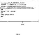
图50是表示本发明的第9实施方式的矢量数据的一例的图。Fig. 50 is a diagram showing an example of vector data according to a ninth embodiment of the present invention.
图51是表示本发明的第9实施方式的注册机器表的一例的图。Fig. 51 is a diagram showing an example of a registered device table according to the ninth embodiment of the present invention.
图52是表示本发明的第9实施方式的布置简图的一例的图。Fig. 52 is a diagram showing an example of a schematic layout diagram of a ninth embodiment of the present invention.
图53是以往的机器控制系统的系统构成图。Fig. 53 is a system configuration diagram of a conventional machine control system.
图中:1、101-远程控制装置(服务器),2、102-终端,3、111-机器,4-存储机构,5-控制对象机器表,6、41、71、82-程序构件文件夹,7-设备信息表,8-用户表,9-应用程序生成机构,10-图像保存文件夹,11、108-接口机构,12、104-WAN,13、113-浏览显示机构,14-运算机构,15-通信机构,16、42、72-控制命令程序,17、43、73-按钮显示程序,18-控制程序,31、151、182、702-IP相机,32-终端辨别机构,44-图像保存命令程序,45-摇动倾斜命令程序,46-变焦命令程序,47-图像保存按钮程序,48-变焦按钮程序,49-摇动倾斜按钮程序,50-图像显示程序,60、185-IP空调,61-变焦按钮,62-图像保存按钮,63、161-摇动倾斜按钮,64-图像显示部,74-ON/OFF命令程序,75-ON/OFF按钮显示程序,81-控制命令表,501、502、503、504、505、506、507、508-机器控制系统,103-LAN,105-数据库部,106-可视配置图DB(数据库),107、1503-机器分类方案表,109-Web生成机构,110-HGW,112、1501-注册机器表,124-服务提供商(ISP),152-图像保存数据库,153-控制程序模块,154-静止图像输出程序模块,162-图像质量调整按钮,163-分辨率切换按钮,164-关闭按钮,165-摇动倾斜按钮,166-静止图像,181、191、903-布置简图,183-IPFAX,184-IP灯,701-人体感知器,704、705-程序模块,706-复合控制设定表,901、902-图符,904-分组区,905-OK按钮,1001-设定项目选择页面,1002-下拉菜单,1003-选择按钮,1010-详细设定页面,1011-详细设定按钮,1012-图像确定按钮,1013-图像,1020-设定确认页面,1021-设定确认窗口,1022-条件确定按钮,1030-动作测试按钮,1031-确认OK按钮,1032-重做按钮,1040-测试执行页面,1041-测试开始按钮,1042-测试结束按钮,1050-矢量数据,1502-部分抽出表。In the figure: 1, 101-remote control device (server), 2, 102-terminal, 3, 111-machine, 4-storage mechanism, 5-control object machine table, 6, 41, 71, 82-program component folder , 7-device information table, 8-user table, 9-application program generation mechanism, 10-image storage folder, 11, 108-interface mechanism, 12, 104-WAN, 13, 113-browsing display mechanism, 14-calculation Mechanism, 15-communication mechanism, 16, 42, 72-control command program, 17, 43, 73-button display program, 18-control program, 31, 151, 182, 702-IP camera, 32-terminal identification mechanism, 44 -Image save command program, 45-Shake and tilt command program, 46-Zoom command program, 47-Image save button program, 48-Zoom button program, 49-Shake and tilt button program, 50-Image display program, 60, 185-IP Air conditioner, 61-Zoom button, 62-Image save button, 63, 161-Shake and tilt button, 64-Image display section, 74-ON/OFF command program, 75-ON/OFF button display program, 81-Control command table, 501, 502, 503, 504, 505, 506, 507, 508-machine control system, 103-LAN, 105-database department, 106-visual configuration diagram DB (database), 107, 1503-machine classification scheme table, 109 -Web generating mechanism, 110-HGW, 112, 1501-registered machine table, 124-service provider (ISP), 152-image storage database, 153-control program module, 154-still image output program module, 162-image quality Adjustment button, 163-Resolution switching button, 164-Close button, 165-Shake and tilt button, 166-Still image, 181, 191, 903-Layout diagram, 183-IPFAX, 184-IP light, 701-Human sensor , 704, 705-program module, 706-compound control setting table, 901, 902-icon, 904-grouping area, 905-OK button, 1001-setting item selection page, 1002-pull-down menu, 1003-selection button , 1010-detailed setting page, 1011-detailed setting button, 1012-image confirmation button, 1013-image, 1020-setting confirmation page, 1021-setting confirmation window, 1022-condition confirmation button, 1030-action test button , 1031-OK button, 1032-Redo button, 1040-Test execution page, 1041-Test start button, 1042-Test end button, 1050-Vector data, 1502-Part extraction table.
具体实施方式Detailed ways
(第1实施方式)(first embodiment)
图1是本发明的第1实施方式中的机器控制系统的系统构成图。FIG. 1 is a system configuration diagram of a machine control system in a first embodiment of the present invention.
本发明的机器控制系统501,是可以从设于远程的终端2,通过作为机器控制装置的服务器1,控制与服务器1连接的多台机器3(图1中仅示出了1台)的系统。The
在这里,机器3与服务器1通过因特网等广域性网络(以下称为WAN)连接。Here, the
机器3具备接受来自服务器1的控制命令WWW服务器等通信机构15;和根据接受的控制命令,使机器动作的控制程序18的模块。The
在这里,作为机器3,例如包含IP照相机、数码相机、数码摄像机、空调、电子加热器、电视机、录像机、打印机等,可以接收来自服务器1的控制命令的所有种类的电子机器。Here, the
终端2,例如具有个人计算机或PDA等的可显示Web网页的浏览显示机构13,可以通过WAN12与服务器1互相发送接收信息。The
服务器1至少具备存储机构4、运算机构14及接口机构11。The
首先,作为存储机构4,可以使用磁盘、光磁盘、半导体存储器等一般使用的数据存储机构。First, as the storage means 4, generally used data storage means such as a magnetic disk, a magneto-optical disk, and a semiconductor memory can be used.
在存储机构4中存储有多个表和文件夹。A plurality of tables and folders are stored in the
作为表的例子,在图12中表示用户表8的示例,在图13中表示控制对象机器表5的示例,在图14中表示设备信息表7的示例。As examples of tables, an example of the user table 8 is shown in FIG. 12 , an example of the controlled device table 5 is shown in FIG. 13 , and an example of the device information table 7 is shown in FIG. 14 .
首先,在用户表8中,存储有用于识别可访问服务器1的用户的信息。作为该识别信息,例如图12所示,存储有用户的ID、姓名、用户名(注册名)、服务器1所确保的可使用的存储机构4的区域量以及口令等信息。First, in the user table 8, information for identifying users who can access the
再有,在用户表8中也可以存储有关向用户提供的服务的标志信息等。作为其中一例,在图12所示的用户表8中,存储有用户是否希望面向移动电话的服务(图中记为移动控制服务)的标志信息。In addition, in the user table 8, it is also possible to store flag information on services provided to users, and the like. As an example, in the user table 8 shown in FIG. 12, flag information indicating whether the user desires a service for mobile phones (referred to as mobile control service in the figure) is stored.
接着,在控制对象机器表5中,如图13所示,存储有针对每个用户,成为其控制对象的机器3的ID、名称、URL、机器的绰号、机器的电源ON/OFF的状态、机器配置的场所等信息。Next, in the control target device table 5, as shown in FIG. 13 , for each user, the ID, name, URL, device nickname, power ON/OFF status of the
接下来,在设备信息表7中,如图14所示,存储有针对各机器(ID、名称等信息),列举了可控制的功能的信息。Next, in the device information table 7 , as shown in FIG. 14 , information listing controllable functions for each device (information such as ID and name) is stored.
在这里,再次返回图1,在程序构件文件夹6中存储有程序构件,程序构件包含:对各种控制命令的每一个,用于将该控制命令向内置在机器3中的的控制程序18传送的采用PHP Hypertext Preprocessor(以下称为PHP)记述的控制命令程序16;和将采用Hyper Text Markup Language(以下称为HTML)记述的用于执行控制命令的按钮等GUI在终端2的浏览显示机构13上进行显示的按钮显示程序17。而且,在附图中,虽然示出了一对控制命令程序16与按钮显示程序17,但对每个可控制的功能都存储有一对程序构件。Here, returning to FIG. 1 again, a program component is stored in the
然后,作为接口机构11,可以使用一般使用的以太网、ISDN、ADSL、电话线、串行、并列等接口。Then, as the interface means 11, commonly used interfaces such as Ethernet, ISDN, ADSL, telephone line, serial, and parallel can be used.
在服务器1上,通过这些接口机构11连接有多台机器3(图中只示出1台)。A plurality of
再有,作为运算机构14,可以使用一般使用的CPU。In addition, as the
在运算机构14中,装入从上述3个表及程序构件中取出必要的信息,进行组合,从而生成应用程序的应用程序生成机构9。In the calculation means 14, the application program generation means 9 which extracts and combines necessary information from the above-mentioned three tables and program components to generate an application program is incorporated.
接着,对使用这种机器控制系统501的机器控制方法进行说明。Next, a machine control method using such a
图2是表示本发明的机器控制方法的流程图。Fig. 2 is a flow chart showing the machine control method of the present invention.
在图2的步骤S102中,首先,用户通过浏览显示机构13从终端2访问服务器1。In step S102 of FIG. 2 , first, the user accesses the
接着,在服务器1中,在步骤S103,由应用程序生成机构9对来访问的用户识别是否为用户表8中注册过的用户。识别一般使用ID与口令进行,若确认为用户已注册过,则进入步骤S104。Next, in the
而且,本发明并未限定于该识别方法。显然也可以构成为用户在注册时采用生物测定法进行识别。Also, the present invention is not limited to this identification method. Obviously, it can also be configured that the user is identified using a biometric method during registration.
在步骤S104中,根据访问服务器1的用户,运算机构14从控制对象机器表5中取得允许用户控制的机器3的种类信息。In step S104 , according to the user accessing the
接下来,在步骤S105中,根据在步骤S104取得的信息,利用应用程序生成机构9生成催促用户从多台机器中选择成为控制对象的机器3的画面,并通过接口机构11及WAN12在终端2的浏览显示机构13上进行显示。Next, in step S105, based on the information obtained in step S104, the application
接着,在步骤S106中,由用户进行成为控制对象的机器3的选择。Next, in step S106, the user selects the
然后,在步骤S107中,应用程序生成机构9从设备信息表7中取得步骤S106中已被选择的机器3中可控制的功能种类相关的信息。Then, in step S107 , the application creation means 9 acquires information on the types of functions controllable in the
接下来,在步骤S108中,应用程序生成机构9从程序构件文件夹6取得成为控制对象的机器3中可控制的功能相关的程序构件,具体地讲对于可控制的一种功能,包含一对按钮显示程序17及控制命令程序16的程序。Next, in step S108, the application
再接着,在步骤S109中,应用程序生成机构9生成利用在步骤S108中取得的按钮显示程序43,可选择地显示已被选择好的机器3的可控制功能菜单的Web网页。并且,通过网络,使Web网页显示于终端2的浏览显示机构13上。Next, in step S109, the application program generating means 9 generates a Web page for selectively displaying the controllable function menu of the selected
接下来,在步骤S110中,由用户选择所希望的控制内容。Next, in step S110, the user selects desired control content.
然后在步骤S111中,用运算机构14执行在步骤S108中取得、在步骤S110中被选择好的功能相关的控制命令程序16。结果是,控制命令等的引用参数,通过接口机构11,送向成为控制对象的机器3。在机器3中,用通信机构15接收控制命令等的引用参数,在控制程序18中执行所希望的控制动作。由此,可以从远程设置的终端2执行对机器3的控制。Then in step S111, the operation means 14 executes the
接着,在步骤S112中,该控制结果被服务器1接受。Next, in step S112, the control result is accepted by the
再接下来,在步骤S113中进行操作是否结束的判断,若结束则结束动作。若未结束,则返回到步骤S110的用户进行的功能选择步骤。Next, in step S113, it is judged whether the operation is finished, and if it is finished, the action is ended. If it is not finished, return to the function selection step performed by the user in step S110.
这样,根据本发明,程序构件可以按照功能类别进行预备,不依赖于机器3的不同。Thus, according to the present invention, program components can be prepared according to functional categories, independent of differences in
因此,即使机器被追加、变更,也没有必要在服务器1中安装新的控制应用程序、驱动器等。另外,也没有制作被追加、变更的机器相关的操作Web网页的必要。Therefore, even if a device is added or changed, it is not necessary to install a new control application program, driver, etc. in the
另外,在同一机器中,在可控制的功能被追加的情况下,没有必要改装控制应用程序、驱动器等,只要追加与所追加的功能相关的程序构件,编辑数据库等即可。In addition, when a controllable function is added to the same device, it is not necessary to modify the control application program, driver, etc., and only need to add program components related to the added function, edit the database, etc.
由此,在可以减轻用户或运用者的负担的同时,与以往比较可以节约存储介质资源。As a result, the load on the user or operator can be reduced, and storage medium resources can be saved compared with conventional ones.
而且,在本实施方式中,虽然服务器1与机器3之间的连接以及服务器1与终端2之间的连接,通过WAN1进行,但服务器1与机器3的连接或服务器1与终端2之间的连接也可以使通过LAN或串行电缆、USB等直接进行连接。Moreover, in this embodiment, although the connection between the
另外,在服务器1与机器3之间的通信线路中,当然也可以经由网关、路由器等。In addition, the communication line between the
(第2实施方式)(second embodiment)
接着,作为本发明的第2实施方式,以在第1实施方式所示的机器控制系统中,由远程控制可传送静止图像的网络照相机(以下称为IP相机)的情况为例进行说明。Next, as a second embodiment of the present invention, a case where a network camera (hereinafter referred to as an IP camera) capable of transmitting still images is remotely controlled in the equipment control system shown in the first embodiment will be described as an example.
图3是本发明的第2实施方式中机器控制系统502的系统构成图。而且,在图3中,对于与图1相同的构成要件,采用相同的标号并省略其说明。FIG. 3 is a system configuration diagram of a machine control system 502 in the second embodiment of the present invention. In addition, in FIG. 3 , the same reference numerals are assigned to the same components as those in FIG. 1 , and description thereof will be omitted.
在本实施方式的机器控制系统502中,在存储机构4中设有图像保存文件夹10。IP相机31通过WAN12与服务器1连接。In the machine control system 502 of this embodiment, an
在本实施方式中,采用从远程的终端2控制IP相机31,进行“摇动(pan)”、“倾斜(tilt)”、“变焦(zoom)”,保存静止图像的控制例进行说明。In this embodiment, an example of controlling the
对于控制方法,再次利用图2进行说明。由于从步骤S102到步骤S104如第1实施方式所述,故省略其说明。The control method will be described using FIG. 2 again. Since steps S102 to S104 are as described in the first embodiment, description thereof will be omitted.
在图2的步骤S 105中,使图5所示的操作画面GUI显示在终端2的浏览显示机构13上。In step S105 of FIG. 2, the operation screen GUI shown in FIG. 5 is displayed on the
图5表示对于注册过的用户名A,A可以操作的机器是IP相机31、IP空调(图中未示出)。在终端2的用户A告知可以用单选按钮选择IP相机31与IP空调。Fig. 5 shows that for the registered user name A, the machines that A can operate are
在图2的步骤S106中,作为控制对象机器,利用图5示出的GUI的单选按钮选择IP相机31。In step S106 of FIG. 2 , the
在步骤S107中,取得A可控制的IP相机31的功能,即操作信息。通过参照图14所示的信息表7或图12所示的用户表8,知道A可控制的功能是“摇动”、“倾斜”、“变焦”。In step S107, the function of the
在步骤S108中,IP相机31的控制所必需的程序构件由程序构件文件夹6,包含在装载在运算机构14的应用程序生成机构9中。In step S108 , program components necessary for controlling the
在所包含的程序构件中,包括图4所示的“摇动”、“倾斜”、“变焦”、“图像保存”所必需的程序。图4表示程序构件文件夹41内存储的程序构件中,应用程序生成机构9所包含的程序构件的一部分。The included program components include programs necessary for "panning", "tilting", "zooming", and "image saving" shown in FIG. 4 . FIG. 4 shows a part of the program components included in the application program generating means 9 among the program components stored in the
例如,作为控制命令程序42,包括用PHP语言记述的图像保存命令程序44、摇动倾斜命令程序45及变焦命令程序46。作为按钮显示程序43,在应用程序生成机构9中包含用HTML记述的图像保存按钮程序47、变焦按钮程序48及摇动倾斜程序49。For example, the
另外,作为其他所必需的程序构件,在应用程序生成机构9中也包含图像显示程序50。In addition, an
接着,在图2的步骤S109中,将图6所示的操作画面GUI显示于终端2的浏览显示机构13上。Next, in step S109 of FIG. 2 , the operation screen GUI shown in FIG. 6 is displayed on the
在图6所示的操作画面GUI上,显示有进行IP相机31的变焦的变焦按钮61、进行摇动或倾斜的摇动倾斜按钮63、图像保存按钮62及IP相机31的名称以及表示上次所取入的图像的图像显示部64。On the operation screen GUI shown in FIG. 6 , a
为了使该图6所示的操作画面GUI显示在终端2的浏览显示机构13上,使用步骤S108中被应用程序生成机构9包含的按钮显示程序43。In order to display the operation screen GUI shown in FIG. 6 on the browse display means 13 of the
接下来,对于程序构件,从摇动倾斜按钮程序49依次对其动作使用附图进行说明。图7是表示摇动倾斜按钮程序49的处理流程的流程图,图21是该程序的记述内容的一例。Next, the operation of the program components in order from the pan and
在图7中,首先,在步骤S72中,将摇动倾斜按钮63显示在浏览显示机构13的操作画面GUI上。In FIG. 7 , first, in step S72 , the pan and
接着,在步骤S73中,进行用户所进行的输入(例如,指示向上倾斜)。Next, in step S73, an input by the user (for example, an instruction to tilt upward) is performed.
接着,在步骤S74中,其摇动倾斜的方向(作为引用参数,Move=↑)被传送至作为摇动倾斜功能的控制命令程序的摇动倾斜命令程序45,摇动倾斜按钮程序49的处理流程结束。Then, in step S74, the direction of its tilt (as a reference parameter, Move=↑) is transmitted to the
接下来,图8表示摇动倾斜命令程序45的处理流程。Next, FIG. 8 shows the processing flow of the pan and
另外,图9表示摇动倾斜命令程序45的PHP程序的记述例。In addition, FIG. 9 shows a description example of the PHP program of the pan and
在图8的步骤S81中,利用摇动倾斜命令程序45接受作为上述摇动倾斜按钮程序49的处理结果的,先前的引用参数(Move=↑)。In step S81 of FIG. 8 , the previous reference parameter (Move=↑) is accepted by the pan
在接下来的步骤S82中,通过接口机构11,将引用参数(Direction=TiltUP)作为控制命令,向IP相机31传送,然后结束。In the next step S82, the reference parameter (Direction=TiltUP) is transmitted to the
具体地讲,在图9所示的程序例中,若move=↑,则执行@fopen(“$deviceURL/cgi-bin/ControlCamera?Direction=TiltUP”,“r”)。Specifically, in the program example shown in FIG. 9 , if move=↑, @fopen("$deviceURL/cgi-bin/ControlCamera?Direction=TiltUP", "r") is executed.
此时,在$deviceURL中,包括图13所示的控制对象机器表5中记载的机器URL(例如,http://a_kitchen_cam.devicecontrolsystem.com)。At this time, $deviceURL includes the device URL (for example, http://a_kitchen_cam.devicecontrolsystem.com) described in the controlled device table 5 shown in FIG. 13 .
IP相机31在其WWW服务器的cgi-bin索引(directory)中具有称为ControlCamera的控制程序。该所谓的ControlCamera的控制程序接受先前的引用参数(Direction=TiltUP),并执行。The
由此,在IP相机31中,进行实际的摇动、倾斜动作。As a result, actual panning and tilting operations are performed in the
这样,可以从设于远程的终端2进行IP相机31的摇动倾斜动作。In this way, the panning and tilting operation of the
而且,在使IP相机31进行变焦动作的情况下,也进行与上述摇动倾斜按钮程序49及摇动倾斜命令程序45的处理的示例相同的处理。图10表示变焦按钮程序48的处理流程,图11表示变焦命令程序46的处理流程。Furthermore, also when the
首先,在图10中,变焦按钮程序48在步骤S92中将变焦按钮61显示在浏览显示机构上。First, in FIG. 10, the
在步骤S93中,若有来自用户的输入,则将变焦的引用参数(Zoom=变焦)向变焦命令程序46传送,然后结束。In step S93, if there is an input from the user, the reference parameter of zoom (Zoom=zoom) is transmitted to the
接着,在图11中,变焦命令程序46接受步骤S11中来自变焦按钮程序48的引用参数。Next, in FIG. 11, the
接下来,在步骤S12中,判断成为控制对象的IP相机31是否有变焦功能。在判断为有变焦功能时,接着在步骤S13中,通过接口机构11将引用参数作为控制命令向IP相机31传送,然后结束。Next, in step S12, it is determined whether or not the
接受该控制命令(Zoom=zoom1),在IP相机31中执行控制程序,可以进行实际的变焦放大功能。Receiving this control command (Zoom=zoom1), the
这样,与摇动倾斜动作同样,可以从设于远程的终端2控制IP相机31的变焦动作。In this manner, the zoom operation of the
而且,在步骤S12中判断为IP相机31内没有变焦功能时,也可以构成为在步骤S14中在应用程序生成机构9中包含命令程序内部执行数码变焦的数码变焦命令程序。Furthermore, when it is determined in step S12 that there is no zoom function in the
这种情况下,由于直到步骤S11的处理与上述相同,故省略。In this case, since the processing up to step S11 is the same as above, it is omitted.
在图11中,若变焦命令程序46从变焦按钮程序48接受引用参数,则在步骤S14中,变焦命令程序46截取图像的一部分,进行放大的数码变焦,输出该被数码变焦的图像,然后结束。In FIG. 11, if the
对想取入用IP相机31摄影的图像的情况进行说明。预先利用图像保存按钮程序47,显示图6中的图像保存按钮62。用户通过选择该图像保存按钮62,可以启动态图像保存命令程序44,进行图像保存,并存储于服务器1的存储机构4的图像保存文件夹10中。A case where it is desired to capture an image captured by the
这样,通过利用按照功能分类的一对程序构件,若为可接收相同的控制命令及引用参数的机器,则可以实现对机器种类的不同没有依赖性的机器控制装置、系统。由此,即使机器被追加、变更,也没有必要重新向服务器1安装或下载控制应用程序、驱动器。另外,若为具有相同功能的机器,则由于可以利用相同的按钮显示程序,故即使在新控制机器种类不同的机器时,也没有安装或下载新程序的必要。再有,也没有重新制作被新追加、变更的机器的操作用Web网页。In this way, by using a pair of program components classified according to functions, as long as the machines can receive the same control commands and reference parameters, it is possible to realize machine control devices and systems that do not depend on differences in machine types. Thereby, even if a device is added or changed, it is not necessary to re-install or download a control application program or a driver to the
根据这些作用,在进行机器的追加、变更时,也由于有关新追加、变更的机器的软件的下载或安装为最小限度,故在可以减轻用户或运用者的负担的同时,可以有效地使用存储介质资源。According to these functions, when adding or changing a device, the download or installation of software related to the newly added or changed device is minimized, so the burden on the user or operator can be reduced, and the storage space can be effectively used. media resources.
而且,在本实施方式中,作为程序构件,显示了图像保存命令程序44、摇动倾斜命令程序45及变焦命令程序46。另外,作为按钮显示程序43,例示了图像保存按钮程序47、变焦按钮程序48及摇动倾斜按钮程序49。但是,程序构件并未限定于这些程序。Furthermore, in the present embodiment, an image save
例如,在考虑IP相机31的控制的情况下,除此以外,也可以使用变更IP相机3 1的分辨率的分辨率切换构件(由分辨率切换按钮显示程序与分辨率切换命令程序构成)。For example, when considering the control of the
另外,考虑从i模式等移动电话远程控制IP相机31,使用与移动电话等终端的显示画面配合,截取图像的图像截取构件(由图像截取显示程序与图像截取命令程序构成)等程序构件,当然也包括在本发明的机器控制装置及机器控制系统内。In addition, it is conceivable to remotely control the
再有,在本发明的实施方式中,按钮显示程序43示出了用HTML文本记述的示例,控制命令程序42示出了用PHP语言记述的示例。然而,本发明并未将记述程序构件的语言限定于任何一种。例如,在使用CGI或其他语言记述时,当然也包含于本发明的机器控制装置及机器控制系统中。In addition, in the embodiment of the present invention, the
例如,考虑从近年来增加的移动电话或PHS等终端2访问服务器1的情况,也可以构成为与移动电话或PHS等所装载的浏览显示机构13配合,准备用MML文本、HDML文本、CHTML文本、开放内容(opencontents)文本等记述的按钮显示程序43。这种情况下,可以做成从多种的终端2例如移动电话或PHS等便携式终端访问服务器1的情况。For example, considering the case of accessing the
还有,也可以构成为如图15的机器控制系统503那样,将应用程序生成机构9与作为软件的终端辨别机构32一起装入运算机构14,对来访问服务器1的终端2的浏览显示机构13的种类等进行辨别。In addition, it can also be configured as the
图16表示这种终端辨别机构32的PHP语言的程序记述示例。FIG. 16 shows an example of program description in PHP language of the terminal identification means 32.
根据这种终端辨别机构32,例如若取得的终端信息中存在DoCoMo文字,则在以下的处理中使用i模式用所预先准备的按钮显示程序43。According to such a terminal identification means 32, if there is a DoCoMo character in the acquired terminal information, for example, the
对于其他种类的终端2,也进行同样的辨别处理,在以后的处理中,使用以与装载的浏览显示机构13的种类对应的语言记述的按钮显示程序43。The same identification process is performed for other types of
通过设置这种终端辨别机构32,在将近年来增加的移动电话、PHS等作为终端2,访问服务器1时,用户没有必要预先注册终端2的种类,可以在来访问的时刻,取得终端2的信息,因而可以利用多种终端,同时可以进一步减轻用户的负担。By providing such a
(第3实施方式)(third embodiment)
本发明的机器控制装置及远程控制系统,并未限定于第2实施方式所述的IP相机31的控制,包括可接收控制命令的所有电子机器。The equipment control device and the remote control system of the present invention are not limited to the control of the
作为一例,在第3实施方式中,对由设于远程的终端使空调的电源开或关的控制进行说明。As an example, in 3rd Embodiment, the control which turns on or off the power supply of an air conditioner by the terminal installed in remote is demonstrated.
图17是本发明的第3实施方式的机器控制系统的系统构成图。Fig. 17 is a system configuration diagram of a machine control system according to a third embodiment of the present invention.
对于与图1相同的构成要件,采用相同的符号并省略说明。The same reference numerals are used for the same components as those in FIG. 1 , and descriptions thereof are omitted.
在机器控制系统503中,IP空调60将可以接收从服务器1传送的控制命令的WWW服务器作为通信机构15。IP空调60通过WAN12与服务器1连接。In the
图22表示程序构件文件夹71内存储的程序构件内,被应用程序生成机构9包含的程序构件的一部分。FIG. 22 shows a part of the program components included in the application program generating means 9 among the program components stored in the
作为在表示第1实施方式所述的机器控制方法的流程的图2的步骤S108中,装入运算机构14的应用程序生成机构9所包含的程序构件,如图22所示,作为按钮显示程序73,包括ON/OFF按钮显示程序75,作为控制命令程序72,包括ON/OFF命令程序。In step S108 of FIG. 2 which shows the flow of the machine control method described in the first embodiment, the program components contained in the application program generating means 9 loaded into the computing means 14 are displayed as buttons as shown in FIG. 22 . 73, including an ON/OFF
图18表示ON/OFF按钮显示程序75的记述例,图20表示ON/OFF命令程序74的记述例。FIG. 18 shows a description example of the ON/OFF
若再次返回图2,对机器控制方法进行说明,则在步骤S109中,执行图18所示的ON/OFF按钮显示程序75。结果,图19所示的催促电源的ON或OFF的GUI被显示于终端2的浏览显示机构13上。Returning to FIG. 2 again to describe the machine control method, in step S109, the ON/OFF
接着,若在步骤S110中从用户选择所希望的控制内容(此时为IP空调60的电源的ON/OFF),则其引用参数被送至ON/OFF命令程序74,执行ON/OFF命令程序74。Next, if the desired control content is selected from the user (at this time, the ON/OFF of the power supply of the IP air conditioner 60) in step S110, its reference parameter is sent to the ON/
具体地讲,在图18所示的ON/OFF命令程序74中,例如在选择了“ON”按钮的情况下,称为“ON”的数据以所谓“act”的名字向“跳转对方的URL”传送。而且,在“跳转对方的URL”中存储有ON/OFF命令程序74。Specifically, in the ON/
接下来,在接收了所谓的“ON”数据的ON/OFF命令程序74中,如图20所示,执行@fopen(“$deviceURL/cgi-bin/Control?Action=ON”,“r”)。Next, in the ON/
在这里,$deviceURL是控制对象机器表5的机器URL的栏目中示出的URL。例如,是如http://a_bedroom_acn.devicecontrolsystem.com的URL。Here, $deviceURL is the URL shown in the device URL column of the control target device table 5 . For example, a URL such as http://a_bedroom_acn.devicecontrolsystem.com.
由此,从服务器1的接口机构11,对作为控制对象机器的IP空调60的“cgi-bin”目录中存在的所谓“Control”的控制程序,要求执行所谓“Action=ON”的控制程序(图2的步骤S111)。Thus, from the
因此,在IP空调60中,利用内置的控制程序,执行所谓“Action=ON”的控制程序,进行接通电源的控制。Therefore, in the
这样,可以从设于远程的终端2进行IP空调60的控制。In this way, the
这样,根据本发明,相对各种机器从服务器输出的只是引用参数。由于若为相同的功能,则使用相同的程序构件即可进行不同种类的机器的控制,故结果是可以大幅度地缩小必要的控制程序的大小。Thus, according to the present invention, only reference parameters are output from the server with respect to various machines. If the functions are the same, different types of machines can be controlled using the same program component, and as a result, the size of the necessary control program can be greatly reduced.
(第4实施方式)(fourth embodiment)
在本发明从上述的第1实施方式到第3实施方式的记载中,揭示了成为控制对象的机器中内置的控制程序的场所或命令及引用参数的记述被预先记载于控制命令程序16中的情况。In the descriptions of the present invention from the above-mentioned first embodiment to the third embodiment, it is disclosed that the location of the control program built in the device to be controlled or the description of commands and reference parameters are previously recorded in the
本发明为了进一步实现多种机器的远程控制操作,可以得到其他的系统构成,作为本发明的第4实施方式,将详细进行说明。In order to further realize the remote control operation of various machines in the present invention, other system configurations can be obtained, and will be described in detail as the fourth embodiment of the present invention.
图24是本发明的第4实施方式中机器控制系统的系统构成图。在图24中,对于与图1或图3相同的构成要件,将采用相同的符号并省略说明。Fig. 24 is a system configuration diagram of a machine control system in a fourth embodiment of the present invention. In FIG. 24 , the same reference numerals are assigned to the same components as those in FIG. 1 or FIG. 3 , and explanations thereof are omitted.
在图24的机器控制系统505中,在服务器1的存储机构4中还设有控制命令表81。In the machine control system 505 of FIG. 24 , a control command table 81 is also provided in the
在控制命令表81中,例如存储有图25所示的信息。In the control command table 81, for example, information shown in FIG. 25 is stored.
在控制命令表81中,存储有可远程控制的各机器的每种功能中,其控制程序的机器内存储的场所相关的信息(例如目录信息)、应传送的命令的记述及引用参数的信息。In the control command table 81, there are stored information related to the location of the control program stored in the device (for example, directory information) for each function of each device that can be remotely controlled, description of the command to be transmitted, and information on reference parameters. .
例如,通过参照图25,知道在所谓“hcm10”的机器中,想进行向上的摇动倾斜时,对所谓“hcm10”的“cgi-bin”的目录中所谓“ControlCamera”的控制程序,也可以传送所谓“Direction=TiltUP”的命令。For example, by referring to FIG. 25, it is known that in the so-called "hcm10" machine, when it is desired to perform upward shaking and tilting, the control program called "ControlCamera" in the "cgi-bin" directory of the so-called "hcm10" can also be transmitted. So-called "Direction=TiltUP" command.
通过设置这种控制命令表,可以简化控制命令程序的内容。By providing such a control command table, the content of the control command program can be simplified.
程序构件文件夹82内存储的控制命令程序用PHP语言记述,也可以包含所谓@fopen(“$deviceURL/$programplace?$Controlcommand”,“r”)的记述。The control command program stored in the program component folder 82 is described in the PHP language, and may include a description called @fopen("$deviceURL/$programplace?$Controlcommand", "r").
接着,对设置了这种控制命令表81情况下的机器控制系统505的机器的远程控制方法,在以下进行说明。Next, the remote control method of the equipment of the equipment control system 505 in the case where such a control command table 81 is provided is demonstrated below.
图23是本发明的第4实施方式的机器控制系统进行的机器远程控制方法的处理流程的流程图。23 is a flowchart of a processing flow of a machine remote control method performed by the machine control system according to the fourth embodiment of the present invention.
在图23中,对表示与图2所示的流程图相同处理步骤的步骤采用相同的符号,并省略说明。In FIG. 23 , steps representing the same processing steps as those in the flowchart shown in FIG. 2 are denoted by the same symbols, and explanations thereof are omitted.
在图23的机器的远程控制方法中,与其他实施方式不同的方面在于,在步骤S110与步骤S111中,作为步骤S114,加入了取得机器的命令信息的步骤。In the remote control method of the machine in FIG. 23 , the difference from other embodiments is that in step S110 and step S111 , a step of acquiring machine command information is added as step S114 .
对于该新加入的步骤S114,详细进行说明。The newly added step S114 will be described in detail.
在步骤S110中若用户选择所希望的功能,则接下来在步骤S114中,控制命令程序根据已被选择的功能,参照控制命令表81的信息。If the user selects a desired function in step S110, then in step S114, the control command program refers to the information in the control command table 81 according to the selected function.
由此,例如,在进行属于IP相机31的所谓hcm10的机器的向上的摇动倾斜动作的情况下,在作为所谓@fopen(“$deviceURL/$programplace?$Controlcommand”,“r”)的控制命令程序的变量的$deviceURL的部分上,参照图13所示的控制对象机器表,加入成为控制对象的IP相机31的URL的“http://a_kitchen_cam.devicecontrolsystem.com”。Thus, for example, in the case of performing an upward pan and tilt operation of the so-called hcm10 device belonging to the
另外,通过参照控制命令表81,将作为IP相机31中的控制程序的场所的“cgi-bin/ControlCamera”加入“$programplace”的部分中,在“$Controlcommand”的部分中加入“Direction=TiltUP”。In addition, by referring to the control command table 81, "cgi-bin/ControlCamera", which is the location of the control program in the
由此,在接下来的步骤S111中,实际上执行的控制命令程序为@fopen(“http://a_kitchen_cam.devicecontrolsystem.com/cgi-bin/ControlCamera?Direction=TiltUP”,“r”)。Therefore, in the next step S111, the actually executed control command program is @fopen("http://a_kitchen_cam.devicecontrolsystem.com/cgi-bin/ControlCamera?Direction=TiltUP", "r").
由此,向收纳于成为控制对象的IP相机31内的所谓“ControlCamera”的控制程序,传送伴有所谓“Direction=TiltUP”的引用参数的命令,可以实现所希望的操作。In this way, a command with a reference parameter of "Direction=TiltUP" can be transmitted to the control program called "ControlCamera" stored in the
通过形成这样的机器控制系统505的构成,对于装载的控制程序不同的多种机器3,通过在控制命令表81中追加记载该控制程序相关的控制程序的场所、控制命令及引用参数等信息,可以进行更多的机器3例如控制程序不同的机器的控制。With such a configuration of the machine control system 505, for various types of
由此,在可以减轻用户或运用者的负担的同时,可以有效地使用存储介质资源。As a result, it is possible to efficiently use storage medium resources while reducing the burden on the user or operator.
(第5实施方式)(fifth embodiment)
图26中表示本发明的第5实施方式的机器控制系统的系统构成图。FIG. 26 shows a system configuration diagram of a machine control system according to a fifth embodiment of the present invention.
本实施方式的机器控制系统506,是从设于远程的终端102,通过作为远程控制装置的服务器101,分析由服务器101传送来的机器控制信息的接收方网络地址,从而可以控制通过进行路由引导动作的家庭网关110(以下称为HGW),与接收方网络地址的表示目的的机器连接的多台机器111(图26中示出机器111A、机器111B、机器111C及机器111D的4台)的系统。The machine control system 506 of this embodiment analyzes the receiver network address of the machine control information sent by the
在这里,机器111与HGW110形成局域网络3(以下称为LAN)。HGW110与服务器101通过因特网等广域网络4(以下称为WAN)连接,机器111内置有接收来自服务器101的控制命令的WWW服务器等通信机构(图中未示出)及执行控制命令用的控制程序模块(图中未示出)。Here, the device 111 and the
而且,如图31所示,也可以在HGW110与服务器101之间插入互联网服务提供商(以下称为ISP)或CATV提供商等服务提供商124。Furthermore, as shown in FIG. 31 , a service provider 124 such as an Internet service provider (hereinafter referred to as an ISP) or a CATV provider may be inserted between the
再度返回图26,所谓的机器111,例如包括IP相机、数码相机、数码摄像机、空调、电子加热器、电视、录像机、打印机等,可接收来自服务器101的控制命令的全部电子机器。Returning to FIG. 26 again, the so-called machine 111 includes, for example, IP cameras, digital cameras, digital video cameras, air conditioners, electric heaters, TVs, video recorders, printers, etc., all electronic machines that can receive control commands from the
终端102,例如具有个人计算机或PDA等可以显示Web网页的浏览显示机构113。终端102与服务器101通过WAN104可以相互发送接收信息。The terminal 102 has, for example, a
在服务器101中,至少内置有数据库部105、Web网页生成机构109、接口机构108。In the
首先,数据库部105设于服务器101的未图示的存储机构之中。作为存储机构,可以使用磁盘、光磁盘、半导体存储器等普遍使用的数据存储机构。存储机构内至少存储有2个表和1个数据库。First, the
作为2个表的示例,图27中表示机器分类方案表107的示例,图28中表示注册机器表112的示例。As examples of the two tables, FIG. 27 shows an example of the machine classification plan table 107, and FIG. 28 shows an example of the registered machine table 112.
首先,在注册机器表112中,关于所连接的可控制的全部机器,在每台机器中分别存储注册机器ID、注册用户ID、可控制的机器的URL(即应被控制的机器的网络地址)、产品类别ID、机器名称、位置信息(X坐标及Y坐标信息或配置机器的建筑物中的楼层数等)、连接状态的标志信息、机器的控制信息(例如,若为照相机等,则是表示摇动倾斜的状态的信息)等信息。First, in the registered machine table 112, with regard to all connected controllable machines, the registered machine ID, the registered user ID, the URL of the controllable machine (that is, the network address of the machine to be controlled) are respectively stored in each machine. ), product category ID, machine name, location information (X-coordinate and Y-coordinate information or the number of floors in the building where the machine is installed, etc.), connection status flag information, machine control information (for example, if it is a camera, etc., It is information indicating the state of shaking and tilting) and other information.
在这里,位置信息在如后所述,机器被图符化,在表示机器的应配置场所的布置简图上重叠显示时参照。位置信息,表示布置简图上的例如以布置简图左上角为原点的X坐标的值、Y坐标的值以及机器的应配置场所的建筑物内的位置信息(图28的注册机器表112中,作为位置楼层,表示建筑物中的楼层数)等。Here, the location information is referred to when the equipment is iconified and displayed superimposed on the layout schematic diagram showing the place where the equipment should be placed as described later. The position information represents the value of the X coordinate, the value of the Y coordinate, and the position information in the building of the place where the machine should be arranged (in the registered machine table 112 of FIG. , as a location floor, indicating the number of floors in the building), etc.
接着,在图27的机器分类方案表107中,按照机器的机器类别,分别存储有产品类别ID、产品目录、产品件号、形式、产品名称、产品的图符图像的文件名、功能名称及其控制命令的记述等与可控制的功能相关的信息。Next, in the machine classification scheme table 107 of FIG. 27, the product category ID, product category, product part number, format, product name, file name, function name and Information related to controllable functions, such as the description of its control commands.
再次返回图26,在数据库部105中还收纳有可视配置图数据库106(以下称为可视配置图DB)。Returning to FIG. 26 again, a visual layout diagram database 106 (hereinafter referred to as a visual layout diagram DB) is also stored in the
在可视配置图DB106中存储有成为控制对象的机器111的应配置场所的布置简图。A schematic layout diagram of a location where the equipment 111 to be controlled is stored in the visible
图29中表示可视配置图DB106中存储的成为控制对象的机器111的应配置场所的布置简图的示例。FIG. 29 shows an example of a schematic layout diagram of a location where the equipment 111 to be controlled is stored in the visual
在可视配置图DB106中存储有表示机器111配置的场所的二维布局信息的布置简图191的二维位图信息。The two-dimensional bitmap information of the layout sketch 191 representing the two-dimensional layout information of the place where the equipment 111 is arranged is stored in the visible
布置简图191,可以预先在Web网页上保存由用户制作而成的图,也可以从扫描仪等读取图像。The layout diagram 191 may be stored in advance on a web page created by the user, or an image may be read from a scanner or the like.
另外,如后所述,也可以构成为在可视配置图DB106中存储该布置简图191的各房间等每个目标的相对位置,即制图类矢量数据。In addition, as will be described later, the visual
布置简图191可以直接利用由扫描仪等读取的BMP形式等的位图信息,或者也可以解析位图像信息,变换为DXF等矢量数据进行存储。关于该构成将在第9实施方式中说明。The layout sketch 191 may directly use bitmap information such as BMP format read by a scanner or the like, or may analyze bitmap information, convert it into vector data such as DXF, and store it. This configuration will be described in the ninth embodiment.
在图26中,作为接口机构108,可以使用普遍使用的因特网、ISDN、ADSL、电话线、串行、并行等接口。从而,服务器101与外部连接的机器111或终端102的信号的发送接收成为可能。In FIG. 26, as the interface means 108, commonly used interfaces such as the Internet, ISDN, ADSL, telephone line, serial, and parallel can be used. Accordingly, it is possible to transmit and receive signals between the
再有,在服务器101的运算机构(图中未示出)中,装入从上述的2个表及可视配置图DB106中取出必要的信息,分别组合,可以生成控制机器111用的Web网页的Web网页生成机构109。In addition, in the computing mechanism (not shown in the figure) of the
作为运算机构,可以使用普遍的个人计算机或工作站等中用的CPU。As the computing means, a CPU used in general personal computers, workstations, and the like can be used.
接着对这种机器控制系统506的动作进行说明。Next, the operation of such a machine control system 506 will be described.
图33是表示机器控制系统506中的机器的远程控制方法的处理步骤的流程图。FIG. 33 is a flowchart showing the processing procedure of the remote control method of the machine in the machine control system 506 .
图34虽然与图28所示相同,但为便于说明,将一部分简略,表示注册机器表1501和机器分类方案表1503之间的数据参照的相关性。以下并用图33及图34进行说明。Fig. 34 is the same as that shown in Fig. 28, but part of it is simplified for the sake of explanation, and shows the correlation of data reference between the registered device table 1501 and the device classification plan table 1503. 33 and 34 are used together for description below.
在图33的步骤S1102中,首先用户从终端102,通过浏览显示机构113访问服务器101。In step S1102 in FIG. 33 , first, the user accesses the
接着,在步骤S1103中,根据来访问服务器101的用户,从注册机器表112将有关许可用户控制的全部机器111的信息读入到装载到运算机构中的Web网页生成机构109。Next, in step S1103, according to the user accessing the
具体地讲,假定在步骤S1102中访问服务器101的用户的注册用户ID为“3”。在步骤S1103中,将“3”作为检索关键词,对图34的注册机器表1501的注册用户ID的列进行检索(区域AA)。其结果制作成部分抽出表1502。由此,可以抽出用户可控制的机器。Specifically, assume that the registered user ID of the user accessing the
接着,在步骤S1104中,从可视配置图DB106,向Web网页生成机构109读入图29所示的机器配置场所的布置简图信息。Next, in step S1104, the schematic layout diagram information of the equipment layout location shown in FIG.
接下来,在步骤S1105中,根据步骤S1103及步骤S1104中取得的信息,在布置简图上重叠显示机器111的图符化后的图像。由此,用Web网页生成机构109生成催促用户从多台机器111中选择成为控制对象的机器,例如图32所示的Web网页。这种Web网页通过接口机构108及WAN104,可以在终端102的浏览显示机构113上阅览。Next, in step S1105, based on the information acquired in steps S1103 and S1104, the iconified image of the equipment 111 is superimposed and displayed on the layout schematic diagram. As a result, the Web page generating means 109 generates a Web page urging the user to select a device to be controlled from among the plurality of devices 111, for example, a Web page as shown in FIG. 32 . Such Web pages can be browsed on the
具体地讲,在步骤S1105中,Web网页生成机构109以图34的部分抽出表1502内存储的可控制的机器的机器类别ID(区域BB)作为检索关键词,参照机器分类方案表1503。由此,Web网页生成机构109取得已被图符化的图像的文件名,从收纳数据库部105的机器图符图像的目录中取得成为控制对象的各机器的图符图像。Specifically, in step S1105, the Web
另外,Web网页生成机构109,从部分抽出表1502,参照位置X、位置Y及位置楼层等位置信息(区域DD),根据该位置信息,在图29所示的布置简图上重叠显示所取得的各机器的图符图像。In addition, the Web
接着,在图33的步骤S1106中,由用户选择成为控制对象的机器111。Next, in step S1106 of FIG. 33 , the user selects the appliance 111 to be controlled.
在步骤S1107中,从机器分类方案表107,向Web网页生成机构109读入在步骤S1106中被选择的机器111的机器种类相关的信息,即产品名称、单个或多个功能名称、单个或多个控制命令等。In step S1107, from the machine classification plan table 107, the information related to the machine type of the machine 111 selected in step S1106 is read into the Web
接下来,在步骤S1108中,Web网页生成机构109生成表示被选择的机器111的可控制的功能菜单的,例如图30所示的机器分类Web网页,并显示在终端102的浏览显示机构113上。Next, in step S1108, the Web
然后,在步骤S1109中,由用户在机器分类Web网页上选择想控制的操作功能内容。Then, in step S1109, the user selects the operation function content to be controlled on the machine classification Web page.
接着在步骤S1110中从机器分类方案表107,通过接口机构108,向成为控制对象的机器111传送实现在步骤S1109中选择好的功能用的控制命令,在机器111中,在通信机构(图中未示出)中接受控制命令,用控制程序模块执行。Next, in step S1110, from the machine classification plan table 107, through the
由此,在机器111中可以执行给定的功能动作。用户可以从远程的终端102进行机器111的所希望的功能的控制。Thus, a given functional act may be performed in machine 111 . The user can control desired functions of the equipment 111 from the
接下来,在步骤S1111中,利用服务器101接收从成为控制对象的机器111传送来的控制结果。Next, in step S1111 , the
接着在步骤S1112中进行操作是否完成的判断。Next, in step S1112, it is judged whether the operation is completed.
若完成则结束动作,若未完成则返回步骤S1109的机器分类Web网页画面中的用户的操作选择。If it is completed, the operation ends, and if it is not completed, it returns to the user's operation selection in the machine classification Web page screen of step S1109.
由于在可视配置图DB106中存储机器的配置场所的布置简图,在注册机器表中存储作为特定可选择的机器的网络地址信息的机器的URL和位置信息,故可以使机器的配置如图32所示,二维显示在催促机器选择的Web网页上。在本发明的机器控制系统506中,用户可以更直观选择成为控制对象的机器111。Since the layout diagram of the configuration place of the machine is stored in the visual configuration map DB106, and the URL and location information of the machine as the network address information of the specific optional machine are stored in the registered machine table, the machine can be configured as shown in the figure. As shown in 32, the two-dimensional display is on the Web page that urges the machine to select. In the machine control system 506 of the present invention, the user can more intuitively select the machine 111 to be controlled.
另外,在本发明的机器控制系统506中,与以往的机器控制系统不同,从设于远程的终端102,不是对HGW,而是对服务器101进行访问。In addition, in the equipment control system 506 of the present invention, unlike the conventional equipment control system, access is made to the
再有,机器111相关的信息,即产品名称、一个或多个功能名称、一个或多个控制命令等也全部存储于服务器101中。Furthermore, the information related to the machine 111 , that is, the product name, one or more function names, one or more control commands, etc. are also all stored in the
因此,关于控制命令等的更新以及追加、变更,可以由服务器的管理者进行,没有各用户各自进行HGW110内积蓄的数据等的保存的必要性。由此减少对用户的负担。Therefore, the update, addition, and change of control commands and the like can be performed by the administrator of the server, and there is no need for each user to individually save the data and the like accumulated in
还有,由于没有必要在HGW110中积蓄成为控制对象的机器111的控制命令等,故没有必要在HGW110中设置大存储机构。由于可以简单构成HGW110,构筑对HGW110的依赖度低的简易的机器控制系统,故也可以减少频繁更换HGW自身的必要。In addition, since it is not necessary to store control commands and the like of the equipment 111 to be controlled in the
而且,在本实施方式中,示出了在服务器101与机器111之间插入HGW110或HGW110及服务提供商124的系统构成。然而,本发明的机器控制系统并未限于此。例如,显然服务器101与机器111之间可以直接通过WAN连接,或者服务器101与机器111之间可以只插入服务提供商124的系统,或者服务器101与机器111之间可以采用通常的电缆或光缆以LAN,或串行、并行、USB等方式直接进行连接。Moreover, in this embodiment, the system configuration which inserted the HGW110 or the HGW110 and the service provider 124 between the
另外,服务器101与终端102的连接,虽然示出的是通过WAN104的连接的构成,但服务器101与终端102之间的连接也可以采用通常的电缆或光缆以LAN,或串行、并行、USB等方式直接进行连接。In addition, although the connection between the
再有,在服务器101与机器111或服务器101与终端102的通信线路中,当然也可以插入其他的网关、路由器等。In addition, other gateways, routers, etc. may of course be inserted into the communication lines between the
(第6实施方式)(sixth embodiment)
接下来,作为本发明的第6实施方式,以在第5实施方式所示的机器控制系统中,自远程控制可以传送静止图像及动态图像的网络照相机(以下称为IP相机)的情况为例,进一步具体地说明。Next, as a sixth embodiment of the present invention, a case where a network camera (hereinafter referred to as an IP camera) capable of transmitting still images and moving images is remotely controlled in the equipment control system described in the fifth embodiment is taken as an example. , to be more specific.
图35是本发明的第6实施方式中机器控制系统的系统构成图。在图35中对于与图26或图3 1相同的构成要件,采用相同的符号并省略说明。Fig. 35 is a system configuration diagram of a machine control system in a sixth embodiment of the present invention. In FIG. 35, the same symbols are used for the same components as those in FIG. 26 or FIG. 31, and explanations are omitted.
在图35的机器控制系统507中,在数据库部105中设有图像保存数据库152。IP相机151与HGW110连接,形成LAN103。HGW110通过WAN104与服务器101连接。In the
在IP相机151中,装载有控制程序模块153及静止图像输出程序模块154。The
在本实施方式中,以控制IP相机151,进行“摇动”“倾斜”,得到静止图像的控制为例进行说明。In this embodiment, the
对于机器控制系统的动作,再次使用图33说明。由于从步骤S1102到步骤S1104如第5实施方式所述,故省略其说明。The operation of the machine control system will be described again using FIG. 33 . Since steps S1102 to S1104 are as described in the fifth embodiment, description thereof will be omitted.
首先,在图33的步骤S1105中,参照可视配置图DB106中存储的布置简图信息和注册机器表112中存储的成为控制对象的机器111的位置信息,用Web网页生成机构109做成具有图32所示操作画面GUI的Web网页。而且,可以用终端102的浏览显示机构113阅览。First, in step S1105 of FIG. 33 , referring to the layout schematic information stored in the visible
在图32中,在布置简图181上重叠显示有已被图符化的IP相机182、IP传真183、IP灯184及IP空调185。In FIG. 32 , an
接着,在图33的步骤S1106中,作为控制对象机器,若用户选择图32所示的显示于Web网页上的机器的图符,则成为控制对象的机器被选择。Next, in step S1106 of FIG. 33 , when the user selects the icon of the device displayed on the Web page shown in FIG. 32 as the control target device, the control target device is selected.
例如,IP相机182的图符被选择。For example, the icon of the
在步骤S1107中,将IP相机151的产品类别ID作为检索关键词,从机器分类方案表107向Web网页生成机构109读入IP相机151的控制所必需的信息,例如功能名称及控制命令等。In step S1107, using the product category ID of the
接着在步骤S1108中,可以用终端102的浏览显示机构113阅览由Web网页生成机构109生成的、符合图30所示的成为控制对象的机器的机器类别Web网页。Next, in step S1108, the
在图30所示出的机器类别Web网页上,面向图30的纸面在左侧上显示有可以进行IP相机151的控制的遥控部,包括进行IP相机151的摇动或倾斜的摇动倾斜按钮161、进行图像质量调整的图像质量调整按钮162、进行分辨率的切换的分辨率切换按钮163以及关闭机器类别Web网页的关闭按钮164等。面向图30的机器类别Web网页的纸面在右侧上显示有自IP相机151返回的信息,即这种情况下显示静止图像。On the machine category Web page shown in FIG. 30 , a remote control unit capable of controlling the
在这里,例如,在左侧选择使其摇动的指示(图30的左摇动按钮)165。将功能名称作为关键词,从成为机器分类方案表107的控制对象的IP相机151存储的信息中检索该控制命令。Here, for example, an instruction to shake is selected on the left (left shake button in FIG. 30 ) 165 . Using the function name as a key, the control command is retrieved from the information stored in the
例如,在使IP相机151进行左摇动动作时,从图27所示的机器分类方案表107的项目中,首先抽出IP相机151的机器相关信息,即第1行所存储的信息。以功能名称“左摇动”(功能名称9)为检索关键词,从该抽出的信息中选择属于对应的控制命令的“/nphControlCamera?Direction=PanLeft”(控制命令9)。For example, when the
这是向成为控制对象的机器,即此时存储于IP相机151内的作为控制程序模块153的“/nphControlCamera”,引入内容为所谓的“Direction=PanLeft”引用参数的控制命令。This is a control command to introduce a so-called "Direction=PanLeft" reference parameter to the device to be controlled, that is, "/nphControlCamera" as the
将该控制命令附加于作为控制对象的机器,即这种情况下作为特定从注册机器表中选择的IP相机151的网络地址信息的机器URL上,并向IP相机151传送。This control command is attached to the device to be controlled, that is, in this case, the URL of the device as network address information specifying the
接着,返回图33,在步骤S1110中,如上所述,执行控制命令。具体地讲,向所谓的IP相机151内存储的作为控制程序模块153的“/nphControlCamera”,传递所谓的“Direction=PanLeft”引用参数。Next, returning to FIG. 33, in step S1110, the control command is executed as described above. Specifically, a so-called “Direction=PanLeft” reference parameter is passed to “/nphControlCamera” as the
此时,在作为控制对象的IP相机151中,用作为控制程序模块153的“/nphControlCamera”,执行“Direction=PanLeft”。由此,IP相机151进行1步左摇动动作。At this time, in the
接下来,在步骤S1111中,服务器101接收该控制结果。Next, in step S1111, the
接着在步骤S1112中判断操作是否完成,若完成则结束动作,若未完成则返回到步骤S1109的机器类别Web网页画面中的用户的操作选择。Then in step S1112, it is judged whether the operation is completed, if it is completed, the action is ended, if it is not completed, then return to the user's operation selection in the machine category Web page screen of step S1109.
这样,可以从设于远程的终端102进行IP相机151的控制。In this way, the
由于通过使用这种机器控制系统507,在可视配置图DB106中存储机器的配置场所的布置简图,在注册机器表中存储可选择的机器的配置信息,故可以使机器的配置如图32所示的二维地显示于催促机器选择的Web网页上。因此,用户可以更直观地选择成为控制对象的机器111,可以远程控制机器111。Because by using this
另外,与以往的机器控制系统不同的是,从设于远程的终端102,不是对HGW110,而是对服务器101进行访问,同时,与机器111相关的信息即产品名称、一个或多个功能名称、一个或多个控制命令等也全部存储于服务器101中。因此,关于控制命令等的更新以及追加、变更,可以由服务器的管理者进行,没有各用户各自进行HGW110内积蓄的数据等的保存的必要性,减少用户的负担。In addition, unlike the conventional machine control system, the
再有,由于没有必要在HGW110中积蓄成为控制对象的机器111的控制命令等,故没有必要在HGW110中设置大的存储机构,可以简单构成HGW110,构筑对HGW110的依赖度低的简易的机器控制系统。由此,也可以减少对HGW自身频繁更换的必要。In addition, since it is not necessary to store the control commands of the equipment 111 to be controlled in the
(第7实施方式)(seventh embodiment)
在本发明的机器控制系统中,通过服务器101进行设于远程的机器111的操作。由此,利用机器所装载的程序模块,不仅是可远程控制的功能,而且将这些组合,可以进行在以往是困难的复合操作。在本实施方式中,举例进行说明。In the machine control system of the present invention, the operation of the machine 111 installed remotely is performed by the
作为本发明的第7实施方式,是以在第6实施方式所说明的IP相机151的控制中,实际上通过点击由IP相机151取得的图像,进行摇动倾斜动作的控制为例进行说明。As the seventh embodiment of the present invention, in the control of the
这是在IP相机151的可控制功能为每个步骤的摇动倾斜的情况下,利用服务器101使多个步骤的摇动倾斜实现的示例。This is an example in which the
而且,由于本实施方式的机器控制系统的系统构成与第6实施方式的系统构成相同,故省略说明。Moreover, since the system configuration of the equipment control system of this embodiment is the same as that of the sixth embodiment, description thereof will be omitted.
再次利用第6实施方式所用的图33说明本实施方式的机器控制系统的动作。由于从步骤S1102到步骤S1107是相同的处理步骤,故省略说明。The operation of the equipment control system of this embodiment will be described again using FIG. 33 used in the sixth embodiment. Since step S1102 to step S1107 are the same processing steps, description thereof will be omitted.
作为在步骤S1108中所表示的机器类别Web网页,显示在图36所示的用IP相机151预先取得并保存的静止图像166上埋入所谓图像1的可点击块图的机器类别Web网页。As the device type Web page shown in step S1108, the device type Web page in which the clickable block diagram of so-called
在这里,表示将所显示的静止图像166分割为纵9、横7合计63块的示例。分别在每块中设定摇动倾斜的变换步骤数。在用于显示机器类别Web网页的所必要的HTML文本中记述成向若点击任何一块则将摇动倾斜控制命令传送给照相机的用PHP语言记述的脚本(在这里为“psnapindex.php3”)传递其设定值。由此,可以由远程使IP相机151执行多步骤的摇动倾斜。以下将更具体地说明。Here, an example is shown in which the displayed still
首先,静止图像166,利用所谓<IMG SRC=‘http://cam01_usera.ip_service.com/SnapshotJPEG?Resolution=320×240’usemap=‘#image1’ismap>的<IMG>标签,显示于远程操作的用户的终端102的浏览显示机构113上。埋入图像内的可点击块图是所谓‘#image1’的名字。First, the
例如,图38表示在设定了图37所示的网格时,称为区域A的部分的“#image1”的可点击块图的数据的一例。For example, FIG. 38 shows an example of data of a clickable block diagram of "#image1" of a part called area A when the grid shown in FIG. 37 is set.
其中,可点击块图的、图像数据的由区域B表示的部分的数据(以下称为可点击数据)如下所记述。<area codes=‘000,000,050,025’href=‘psnapindex.php3?P=-3&T=4&C=cont&camurl=http://cam01_usera.ip_service.com/SnapshotJPEG?Resolution=320×240’>Among them, the data (hereinafter referred to as clickable data) of the part of the image data indicated by the area B in the clickable block diagram is described as follows. <area codes='000,000,050,025' href='psnapindex.php3? P=-3&T=4&C=cont&camurl=http://cam01_usera.ip_service.com/SnapshotJPEG? Resolution=320×240'>
因此,若点击图像的最左上端,则向作为用PHP语言记载的脚本“psnapindex.php3”脚本传递?以后的引用参数,由此执行处理。Therefore, when the uppermost left end of the image is clicked, is it passed to the script "psnapindex.php3" which is described in the PHP language? Subsequent reference parameters are processed accordingly.
在上述数据中,P=-3意味着执行3步左摇动。另外T=4意味着执行4步上倾斜。C=cont表示在图像上点击。在这种情况下,表示成为摇动倾斜的控制模式。In the above data, P=-3 means that 3-step left panning is performed. Also T=4 means that 4 steps up ramp are performed. C=cont means click on the image. In this case, it shows that it is a pan and tilt control mode.
接下来对“psnapindex.php3”脚本(以下称为摇动倾斜脚本)进行详细说明。在摇动倾斜脚本中,进行图39所示的处理流程的记述。Next, the "psnapindex.php3" script (hereinafter referred to as the shake and tilt script) will be described in detail. In the pan and tilt script, the processing flow shown in FIG. 39 is described.
首先,在步骤S1601中进行是否为摇动倾斜模式的判断。具体地讲,判断可点击数据的所谓C=cont的记述的有无。First, in step S1601, it is determined whether it is the pan and tilt mode. Specifically, the presence or absence of a description of so-called C=cont in the clickable data is judged.
接着在步骤S1602中进行所要求的摇动是左还是右的判断。具体地讲,判断可点击数据中的变量P是否为正的值。Next, in step S1602, it is judged whether the required shaking is left or right. Specifically, it is judged whether the variable P in the clickable data is a positive value.
在步骤S1602中,若判断P的值为正,则接下来在步骤S1603中将P值的绝对值代入变量N内,将0代入计数器Count的值内。In step S1602, if it is determined that the value of P is positive, then in step S1603, the absolute value of P is substituted into the variable N, and 0 is substituted into the value of the counter Count.
接下来在步骤S1604中,从服务器101,向IP相机151的内部内置的控制程序,具体地讲根据以下PHP语言的记述,向作为控制程序模块153的nphControlCamera传送伴有所谓Direction=PanRight的引用参数的控制命令。Next, in step S1604, from the
@fopen(“$camurl/cgi-bin/nphControlCamera?Direction=PanRight”,“r”)@fopen("$camurl/cgi-bin/nphControlCamera?Direction=PanRight", "r")
这种情况下$camurl是特定IP相机151的网络地址信息,代入从注册机器表中选择的IP相机151的URL。In this case, $camurl is the network address information of the
接着,在步骤S1904中,计数器Count被增加。接下来在步骤S1605中判断变量N是否比计数器Count大,在为“是”的情况下进入步骤S1605,在为“否”的情况下返回步骤S1604。Next, in step S1904, the counter Count is incremented. Next, in step S1605, it is judged whether the variable N is larger than the counter Count, if it is "Yes", it goes to step S1605, and if it is "No", it returns to step S1604.
即,仅以用户所希望的次数在IP相机151中进行摇动动作。That is, the
将以上所说明的从步骤S1603到步骤S1605的处理作为右摇动处理。在步骤S1602中摇动为左,具体地讲变量P的值为负时,进行步骤S1606中记述的左摇动处理。The processing from step S1603 to step S1605 described above is referred to as right panning processing. If the panning is left in step S1602, specifically, when the value of the variable P is negative, the left panning process described in step S1606 is performed.
在步骤S1606的左摇动处理中,进行与上述的右摇动处理同样的处理。但是,与在步骤S1604中执行的程序不同的是,成为@fopen(“$camurl/cgi-bin/nphControlCamera?Direction=PanLeft”,“r”),可以向左实现所希望次数的摇动控制。In the left panning process in step S1606, the same process as the above-mentioned right panning process is performed. However, unlike the program executed in step S1604, as @fopen("$camurl/cgi-bin/nphControlCamera?Direction=PanLeft", "r"), the desired number of panning controls can be realized to the left.
接下来,在步骤S1607中进行作为与上述右摇动处理及左摇动处理同样的处理的倾斜处理。Next, in step S1607, tilt processing is performed, which is the same processing as the above-described right pan processing and left pan processing.
内容与右摇动处理及左摇动处理同样。例如,若为向上的倾斜,则向控制程序传送“Direction=TiltUP”。若为向下的倾斜,则传送所谓“Direction=TiltDown”的命令。由于其他处理是相同的,故省略说明。The content is the same as that of the right panning process and the left panning process. For example, if it is an upward tilt, "Direction=TiltUP" is sent to the control program. If it is a downward tilt, a so-called "Direction=TiltDown" command is transmitted. Since other processes are the same, descriptions are omitted.
接着在步骤S1608中,由IP相机151取入静止图像,并显示在画面上。具体地讲,执行以下的记述内容<IMG SRC=‘$camurl/cgi-bin/SnapshotJPEG?Resolution=320×240&Quality=Standard’usemap=‘#image1’ismap>。Next, in step S1608, a still image is captured by the
根据该记述,向成为控制对象的IP相机151传送作为静止图像输出程序模块1 54的,在“SnapshotJPEG”中伴有所谓“Resolution=320×240&Quality=Standard’usemap=‘#image1’ismap”的引用参数的命令,结束摇动倾斜脚本。According to this description, what is transmitted as a still image
根据本发明,在服务器101中也可以自由地形成如前所述的进行可点击块图的机器类别Web网页的记述。According to the present invention, the
例如,即使在IP相机151自身中只装载有进行每个步骤的摇动倾斜的功能的情况下,根据本发明,也可以对成为控制对象的机器111使多个步骤的摇动倾斜动作一次执行。For example, even if the
而且,在本发明的实施方式中,示出了使机器类别Web网页显示用的记述为HTML文本,用PHP语言记述摇动倾斜脚本的示例。但本发明并未将记述的语言限定于任何一种。例如,使用CGI或其他语言记述的情况当然也包括在本发明的机器控制装置、机器控制系统中。Furthermore, in the embodiment of the present invention, an example is shown in which the description for displaying the machine type Web page is made into HTML text, and the pan and tilt script is described in the PHP language. However, the present invention does not limit the description language to any one. For example, descriptions using CGI or other languages are of course also included in the machine control device and machine control system of the present invention.
例如,考虑从近年来增加的移动电话或PHS等终端2访问服务器1的情况,通过与移动电话或PHS等所装载的浏览显示机构13配合,准备例如用MML文本、HDML文本、CHTML文本、(open contents)文本等记述的Web网页或机器类别Web网页,可以从多种终端102例如移动电话或PHS等便携式终端访问服务器101。For example, considering the situation of accessing the
(第8实施方式)(eighth embodiment)
再有,在本发明的远程控制系统中,例如显示在二维室内结构布置简图上配置了成为控制对象的机器的图符的Web网页。由此,对于用户来说,容易直观理解,设定成多台机器的功能联动动作,即当IP相机检测到移动体则点亮房间的灯等,或设定成使用多台机器的操作,即在点亮正门的门灯的同时也点亮厨房门的屋外灯等。以下将这些控制的内容称为复合动作。Furthermore, in the remote control system of the present invention, for example, a Web page in which an icon of a device to be controlled is arranged on a two-dimensional indoor structural layout diagram is displayed. Therefore, it is easy for the user to intuitively understand, set the function linkage action of multiple machines, that is, light up the lights in the room when the IP camera detects a moving object, or set the operation using multiple machines, That is, while lighting the door light at the main entrance, the outdoor light of the kitchen door is also turned on. Hereinafter, the contents of these controls are referred to as compound actions.
作为本发明的第8实施方式,对使用本发明的机器控制装置及机器控制系统,设定多台控制对象机器的复合动作的示例进行说明。As an eighth embodiment of the present invention, an example in which combined operations of a plurality of control target machines are set using the machine control device and the machine control system of the present invention will be described.
图40表示本发明的第8实施方式的机器的远程控制方法的处理流程的流程图,图41是机器控制系统的系统构成图。FIG. 40 is a flow chart showing the processing flow of the remote control method of the equipment according to the eighth embodiment of the present invention, and FIG. 41 is a system configuration diagram of the equipment control system.
在图41中,对于与图26相同的构成要件,采用相同的符号并省略说明。In FIG. 41 , the same reference numerals are assigned to the same components as those in FIG. 26 , and explanations thereof are omitted.
在本实施方式的机器控制系统508中,HGW110上连接有多台成为控制对象的机器。在图41中,为了简化说明,只示出了IP人体感知器701与IP相机702。In the appliance control system 508 of this embodiment, a plurality of appliances to be controlled are connected to the
每台控制对象机器内置有各自控制中使用的程序模块704、705。The program modules 704 and 705 used for the respective control are incorporated in each control target device.
另外,在本实施方式的机器控制系统508中,在服务器101的数据库部105中装载有在设定了多台机器的复合控制时应存储该详细的设定信息的复合控制设定表706。关于复合控制设定表706的详细内容将在后面阐述。Moreover, in the machine control system 508 of this embodiment, the
以下根据图40说明本发明的第8实施方式的机器控制方法。Next, a device control method according to an eighth embodiment of the present invention will be described with reference to FIG. 40 .
在这里,作为示例,对当成为控制对象的机器中设于正门的IP人体感知器701感知到人体,则用正门的IP相机702以5秒的间隔取得静止图像并保存的控制设定的情况的说明。Here, as an example, when the IP human body sensor 701 installed at the front gate of the equipment to be controlled detects a human body, the IP camera 702 at the front gate acquires still images at intervals of 5 seconds and saves the control settings instruction of.
首先,在步骤S1701中,用注册机器表从来访问的用户的注册用户ID中抽出用户可控制的机器,并在从可视配置图DB取出的机器配置场所的布置简图上重叠显示。由此,可以在终端102的浏览显示机构113上阅览进行控制对象机器的选择的图42所示的Web网页。First, in step S1701, the user-controllable equipment is extracted from the registered user ID of the accessing user using the registered equipment table, and displayed superimposed on the layout diagram of the equipment arrangement location extracted from the visible layout diagram DB. Thereby, the Web page shown in FIG. 42 for selecting a control target device can be browsed on the browsing display means 113 of the terminal 102 .
在图42所示的Web网页中,在预先存储于可视配置图DB106内的布置简图903上,参照注册机器表112的位置X、位置Y及位置楼层等位置信息,重叠显示参照机器分类方案表而取出的机器的图符化图像,即IP人体感知器的图符901及IP相机的图符902。In the Web page shown in FIG. 42 , on the
接着,返回图40,在步骤S1702中用户选择欲进行复合控制的多台机器。Next, returning to FIG. 40, in step S1702, the user selects a plurality of machines to be controlled in combination.
具体地讲,如图43所示,将IP人体感知器的图符901及IP相机的图符902拖放至分组存储区904(图中记为设定箱)。Specifically, as shown in FIG. 43 , drag and drop the
接下来在步骤S1703中判断OK按钮905是否已被按下,若已被按下,则判断为选择结束,进入下一步骤S1704。在未判断为选择结束的情况下,返回步骤S1702。在本实施方式中,选择IP人体感知器701与IP相机702。Next, in step S1703, it is judged whether the
接着,在步骤S1704中利用步骤S1702中选择好的机器的组合,显示设定项目选择页面。Next, in step S1704, using the device combination selected in step S1702, a setting item selection page is displayed.
图44中表示设定项目选择页面1001的示例。在设定项目选择页面1001中,根据下拉菜单1002,可选择地显示与在步骤S1702中选择好的机器所对应的复合动作。An example of the setting
该复合动作是通过读出注册机器表112中存储的机器名称和机器分类方案表107中存储的功能名称信息,使之组合而被显示的。This composite action is displayed by reading out the device name stored in the registered device table 112 and the function name information stored in the device classification scheme table 107, and combining them.
然后,在步骤S1705中,用户由下拉菜单1002选择所希望的复合动作,通过按下选择按钮1003,结束复合动作的选择。在本实施方式中,作为复合动作,是在正门感知器(表示IP人体感知器701)“ON”下选择正门照相机(表示IP相机702)“静止图像保存”。Then, in step S1705, the user selects a desired compound action from the pull-
接下来,在步骤S1706中,显示用户进行在步骤S1705中选择好的复合动作的详细设定用的详细设定页面。Next, in step S1706, a detailed setting page for the user to perform detailed setting of the composite action selected in step S1705 is displayed.
具体地讲,可以用终端102的浏览显示机构113阅览图45所示的详细设定页面1010。Specifically, the
在详细设定页面1010上显示有用IP相机702摄取的图像1013。An
用户通过在接下来的步骤S1707中一边看图像1013,一边按下详细设定按钮1011,进行保存图像的分辨率或图像的旋转角等图像相关的详细设定。By pressing the
而且,在本实施方式中,详细设定按钮1011是进行IP相机702的控制用的多个按钮。在这里,通过操作详细设定按钮1011,如本发明的第7实施方式所示,在作为特定从注册机器表中选择好的IP相机702的网络地址信息的机器URL上附加必要控制命令,并向内置于IP相机702的程序模块705传送。由此,用户若看到此时用IP相机702所摄图像1013,确定所希望的角度,则可以按下图像确定按钮1012,结束设定。Furthermore, in the present embodiment, the
若按下图像确定按钮1012,确定图像,则显示图46所示的复合自动控制设定页面。具体地讲,在设定确认窗口1021中显示输入开始复合自动控制的“开始日期时间”用的输入文字框;输入显示作为静止图像保存的触发器(trigger)的“保存开始条件”的既定条件的文字显示;表示保存静止图像的时间间隔的“静止图像保存时间间隔”用的输入文字框;以及时间单位选择单选按钮、通知静止图像保存开始的“通知邮件”的必要性相关的单选按钮和输入通知邮件的邮件地址用的输入文字框。When the
根据向各文字框的记入或单选按钮的选择,进行详细的复合自动控制设定。在进行了详细设定后,通过按下条件确定按钮1022,向步骤S1708移动。Detailed complex automatic control settings are performed by writing in each text box or selecting a radio button. After the detailed settings are made, by pressing the
接着在步骤S1708中,显示确认已设定的内容的设定确认页面。Next, in step S1708, a setting confirmation page for confirming the set content is displayed.
具体地讲,显示图47所示的设定确认页面1020。在设定确认页面1020中,显示以在步骤S1707确定的角度用IP相机702摄取的图像1013以及一览显示详细设定的设定确认窗口1021。Specifically, the setting
在设定确认窗口1021中,用图46的复合自动控制设定页面设定的信息显示于文字框内。由于这里显示的信息已经用图40的步骤S1707说明,故省略说明。In the
用户在必须变更的情况下按下重做按钮1032,返回S1707,可以重新进行设定。之后,用户在用设定确认窗口1021中表示的设定进行确定时,选择确认OK按钮1031,结束详细设定的确认。The user presses the
接下来,在步骤S1709中,通过按下图47所示的动作测试按钮1030,显示图48所示的测试执行页面1040。Next, in step S1709, by pressing the
用户通过选择测试开始按钮1041,开始动作测试,通过选择测试结束按钮1042,结束动作测试。The user selects the
若动作测试开始,则目前的动作测试状况显示于测试执行页面1040内的右上角上。其内容是正门感知器的状态或用正门照相机取得的静止图像的张数、以文字保存的图像的确认、以文字保存的图像的删除等。If the action test starts, the current action test status is displayed on the upper right corner of the
另外,在步骤S1709中,在不进行动作测试时或进行了动作测试后,在接下来的步骤S1710中,在选择了确认OK按钮1031的情况下,设定、存储完成图41所示的复合控制设定表706的设定信息。In addition, in step S1709, when the operation test is not performed or after the operation test is performed, in the next step S1710, when the confirmation
图49中表示本发明的复合控制设定表706的一例。An example of the composite control setting table 706 of the present invention is shown in FIG. 49 .
在图49所示的复合控制设定表706中,存储有每行所设定的复合控制相关的信息。In the composite control setting table 706 shown in FIG. 49, information related to the composite control set for each row is stored.
复合控制ID是付与在复合控制的注册顺序上的ID号码,注册用户ID是用户分别具有的ID。在其设定的控制完全结束时在SETEND中写入1。The complex control ID is an ID number assigned to the registration order of the complex control, and the registered user ID is an ID that each user has. Writes 1 in SETEND when the control for which it was set is completely ended.
另外,在即使是设定的继续中也强制性地使其结束时,在FORCEEND中写入1。在开始时刻,输入用户已注册的控制开始时刻。在机器数的栏中写入已选择好的机器的数量。在机器1的栏中登记与用户在控制对象机器中选择的机器名称(正门感知器)对应的注册机器表112所注册的机器ID。在机器1条件中登记机器1的输出的时间性条件。hold表示最初成为机器1真输出栏的值以后保持条件的时间,interval表示最初输出以后输出的时间间隔。Also, write 1 to FORCEEND to forcibly end the setting even if it is continuing the setting. In the start time, enter the control start time that the user has registered. Write the number of selected machines in the machine number column. The device ID registered in the registered device table 112 corresponding to the device name (front door sensor) selected by the user among the control target devices is registered in the column of the
接下来,temp1的初始值时开始日期时间,若机器1以机器1控制输出机器1真输出,则将机器1条件栏内记载的时间加在当前时间上,并且服务器将该日期时间登记于temp1栏内。机器1控制是在第1控制对象机器中用户选择的功能名称,机器1真输出是将机器1控制栏记载的功能输出使用于条件转移时的真值。最终输出保存表示是否将最终的输出结果保存于服务器内,邮件通知存储邮件通知时的邮件地址。Next, the initial value of temp1 is the date and time. If
再有,在结束时刻,输入用户已登记的控制结束时间。In addition, at the end time, the control end time registered by the user is input.
即,在图49所示的复合控制设定表706中,最上1行(复合控制ID=1)的记载表示:自动控制ID:1情况下的注册用户ID:在1的usera的设定中,从2001年7月7日7时00分到7月8日7时00分,注册机器ID:若2的正门感知器输出为ON,则在5分钟期间,以5秒间隔保存正门照相机的静止图像输出,用电子邮件向usera@ip#service.com通知该信息的被复合设定的内容。That is, in the combined control setting table 706 shown in FIG. 49 , the description in the top row (combined control ID=1) indicates that the registered user ID in the case of automatic control ID: 1: in the setting of usera of 1 , from 7:00 on July 7, 2001 to 7:00 on July 8, 2001, register the machine ID: if the output of the front door sensor of 2 is ON, then during 5 minutes, save the front door camera at 5 second intervals For still image output, notify usera@ip#service.com of the compounded contents of the information concerned by e-mail.
另外,图49的复合控制设定表706中第2行(复合控制ID=2)的记载表示:注册用户ID:在2的userb的设定中,从2001年7月17日22时00分到7月18日8时00分,注册机器ID:以10分钟间隔保存3的起居室CAM的静止图像输出,用电子邮件向usera@ip#service.com通知该信息的被复合设定的内容。In addition, the record in the second row (multiple control ID=2) in the composite control setting table 706 of FIG. By 8:00 on July 18, register the device ID: Save the still image output of the living room CAM of 3 at 10-minute intervals, and notify usera@ip#service.com of the content of the composite setting of the information by email .
这样,本发明从终端102访问服务器101,利用服务器101进行机器111的全部控制。由此,通过使用具有高运算能力的服务器101,也可以简单地实现在以往HGW110的处理能力的情况下难的复合使用多台机器111的控制的设定。In this way, the present invention accesses the
而且,在本实施方式中,虽然表示了通过将多台机器111的图符拖放至分组区内,进行机器的复合控制的设定的示例,但本发明并未限于此,例如也可以构成为通过将多台机器111的图符拖放至分组区,机器的复合操作例如在一方机器为电视,另一方机器为录像机时,自动开始录像等复合操作。In addition, in this embodiment, although an example is shown in which multiple devices 111 are dragged and dropped into the grouping area, the setting of complex control of devices is performed, but the present invention is not limited thereto. For example, when one machine is a TV and the other machine is a video recorder, the combined operation of the machines will automatically start such as video recording by dragging and dropping the icons of multiple machines 111 into the grouping area.
再有,在本实施方式中,虽然表示了通过将多台机器111的图符拖放至分组区内,进行机器的复合控制的设定或操作的示例,但本发明的机器控制装置或机器控制系统并未限于此。例如,也可以构成为通过将一方机器的图符拖放至另一方机器的图符上,进行机器的复合控制的设定或操作。In addition, in the present embodiment, although an example is shown in which multiple machines 111 are dragged and dropped into the grouping area, setting or operation of complex machine control is performed, but the machine control device or machine of the present invention The control system is not limited thereto. For example, by dragging and dropping the icon of one device onto the icon of the other device, setting or operation of complex control of the device may be performed.
(第9实施方式)(ninth embodiment)
本发明的第9实施方式中的机器控制系统的系统构成是与第8实施方式中使用的机器控制系统508同样的系统构成。The system configuration of the equipment control system in the ninth embodiment of the present invention is the same as that of the equipment control system 508 used in the eighth embodiment.
在本实施方式中,与第8实施方式不同的方面在于,在可视配置图DB106中存储有DXF等矢量数据。This embodiment is different from the eighth embodiment in that vector data such as DXF is stored in visual layout diagram DB106.
由此,在从第5实施方式到第8实施方式所述的效果基础上,还可以达到不需要由用户选择进行复合控制的机器,即可执行在以往困难的复合操作的特别效果。In this way, in addition to the effects described in the fifth to eighth embodiments, the special effect of performing complex operations that were conventionally difficult can be achieved without requiring the user to select a device for complex control.
以下,参照附图详细地说明。Hereinafter, it demonstrates in detail with reference to drawings.
本实施方式的DXF等矢量数据(以下称为矢量数据)1050是图50所示的文字数据。Vector data such as DXF (hereinafter referred to as vector data) 1050 in this embodiment is character data as shown in FIG. 50 .
图50所示的矢量数据1050是表示图52所示的房间的示意图。对于称为“usera”的用户,记述配置在该建筑物的一层的机器的信息,以所谓“useralf.txt”的文件名存储于可视配置图DB106中。该文件名表示称为usera的用户的1层的数据。
在矢量数据1050中,在每行中记载每间应配置机器的房间的信息。In the
例如,若对用图50的虚线包围的行进行说明,则记述有Room,LD,7,450,90,720,90,720,810,360,810,360,270,450,270,450,90的信息。这些是表示图52所示的房间中用虚线包围的称为LD的房间的数据。For example, when describing the lines surrounded by dotted lines in FIG. 90 information. These are data representing a room called LD surrounded by a dotted line among the rooms shown in FIG. 52 .
其中,开始的“Room”表示作为对象的房间等目标的属性,接着的“LD”是作为对象的房间等的名字。Among them, the first "Room" indicates the attribute of the object such as the target room, and the following "LD" is the name of the target room or the like.
在这里,目标的属性若为房间,则是“Room”,另外,若为家具,则是“Furniture”等,表示该目标是什么。Here, if the attribute of the object is a room, it is "Room", and if it is furniture, it is "Furniture", etc., indicating what the object is.
接下来的“7”表示在房间的角的数量上加1的值,若为这种情况,则表示称为“LD”的具有“Room”属性的房间具有6个角。The following "7" represents a value obtained by adding 1 to the number of corners of the room, and in this case, it means that the room called "LD" having the attribute "Room" has six corners.
接下来,“450,90,720,90,720,810,360,810,360,270,450,270,450,90”,以各2个数字表示各角的坐标。Next, "450, 90, 720, 90, 720, 810, 360, 810, 360, 270, 450, 270, 450, 90" represents the coordinates of each corner with two numbers each.
即,开始的“450,90”在图52中表示以图中左上角为原点时角1的X坐标及Y坐标。接下来的“720,90”表示角2的坐标,“720,810”表示角3的坐标,“360,810”表示角4的坐标,“360,270”表示角5的坐标,“450,270”表示角6的坐标,“450,90”再次表示角1的坐标。That is, the first "450, 90" in FIG. 52 indicates the X-coordinate and Y-coordinate of the
即,通过将这些坐标数据连接,确定作为对象的房间等目标的形状。That is, by connecting these coordinate data, the shape of an object such as a target room is specified.
这种数据预先由用户用鼠标等指示器(pointing device)进行的拖放等输入,或从可视配置图DB106读入。Such data is previously input by the user by dragging and dropping a pointing device such as a mouse, or is read from the visual
根据这种构成,由用户在成为控制对象的机器的图符被配置时,在运算机构中参照图51所示的注册机器表112的位置X及位置Y的信息,从矢量数据1050确定配置了成为控制对象的机器的房间等目标。According to this configuration, when the icon of the device to be controlled is arranged, the user refers to the information of the position X and the position Y of the registered device table 112 shown in FIG. A target such as a room of a machine to be controlled.
例如,如图51所示的注册机器表112的最下列所示,在注册机器ID4号机器分组信息栏中,存储所谓usera/group/1f1d/cam02的信息。For example, as shown in the lowest column of the registered device table 112 shown in FIG. 51, information called usera/group/1f1d/cam02 is stored in the registered device ID No. 4 device group information column.
这表示作为称为“usera”的用户的分组信息,对于所谓1F的1d的房间usera来说,是第2台IP相机。This indicates that the group information of the user called "usera" is the second IP camera for the room usera of 1d in the so-called 1F.
这样,通过在每台成为控制对象的机器中存储所谓配置于哪间房间的分组信息,在进行第8实施方式所示的复合动作时,可以参照分组信息只抽出配置于同一房间的机器,选择成为控制对象的机器。由此,在可以实现以往没有的复合动作的同时,可以进一步减轻用户的负担。In this way, by storing the group information of which room is installed in each of the devices to be controlled, when performing the composite operation shown in the eighth embodiment, only the devices installed in the same room can be extracted by referring to the group information, and selected. A machine to be controlled. As a result, it is possible to further reduce the burden on the user while realizing compound motions that have not been done before.
例如,在为了逼退侵入住所的可疑者,在某个房间配置IP相机,每隔规定时间一边使其摇动,一边进行移动体检测时,将其摇动方向作为摇动信息,存储在注册机器表112中。由此,在利用IP相机检测到移动体的情况下,从矢量数据中取得具有IP相机的房间和该房间周围房间的位置的相对关系,通过参照进行过移动体检测时的摇动信息,可以知道检测到该移动体的房间。For example, when an IP camera is installed in a certain room in order to drive away a suspicious person who has entered the residence, and a moving object is detected while shaking it every predetermined time, the shaking direction is stored in the registered device table 112 as shaking information. middle. Thus, when a moving object is detected by an IP camera, the relative relationship between the position of the room with the IP camera and the surrounding rooms is obtained from the vector data, and by referring to the shaking information when the moving object is detected, it can be known The room where the moving object was detected.
然后,通过使该房间的IP灯点亮,可以防止可疑的侵入。Suspicious intrusions can then be prevented by having the IP lights in that room illuminated.
这样,根据本实施方式所示的机器控制系统,在从第5实施方式到第8实施方式所示的效果的基础上,可以在注册机器表112中存储特定机器的房间的信息或机器的摇动信息等所希望的信息。组合这些,可以构成既可进行以往未有的新的机器间的复合操作,也不对用户造成过大负担的系统。In this way, according to the machine control system shown in this embodiment, in addition to the effects shown in the fifth to eighth embodiments, it is possible to store the room information of the specific machine or the shaking of the machine in the registered machine table 112. desired information such as information. By combining these, it is possible to configure a system that can perform complex operations between new machines that have never been done before without imposing an excessive burden on the user.
如上所述,若使用本发明的机器控制装置及机器控制系统,则从而可以提供一种即使在成为控制对象的机器被追加、变更,或变更了该机器的可控制功能等的情况下,也可以将下载数据的机会降低到最小限度,减少对用户或运用者所造成的负担,不会浪费使用存储介质资源的机器控制装置、机器控制系统以及机器的控制方法。As described above, if the machine control device and the machine control system of the present invention are used, it is possible to provide a machine that can be controlled even when the machine to be controlled is added or changed, or the controllable function of the machine is changed. A machine control device, a machine control system, and a machine control method that can minimize the chance of downloading data, reduce the burden on users or operators, and not waste storage medium resources.
Claims (28)
Applications Claiming Priority (4)
| Application Number | Priority Date | Filing Date | Title |
|---|---|---|---|
| JP2001240815AJP2003052092A (en) | 2001-08-08 | 2001-08-08 | Equipment control device and equipment control system |
| JP240815/2001 | 2001-08-08 | ||
| JP240814/2001 | 2001-08-08 | ||
| JP2001240814AJP2003052093A (en) | 2001-08-08 | 2001-08-08 | Equipment remote control device and equipment remote control system |
Publications (1)
| Publication Number | Publication Date |
|---|---|
| CN1539250Atrue CN1539250A (en) | 2004-10-20 |
Family
ID=26620190
Family Applications (1)
| Application Number | Title | Priority Date | Filing Date |
|---|---|---|---|
| CNA028155327APendingCN1539250A (en) | 2001-08-08 | 2002-07-31 | Machine control device and machine control system |
Country Status (4)
| Country | Link |
|---|---|
| US (1) | US20030038730A1 (en) |
| EP (1) | EP1416760A1 (en) |
| CN (1) | CN1539250A (en) |
| WO (1) | WO2003015450A1 (en) |
Cited By (9)
| Publication number | Priority date | Publication date | Assignee | Title |
|---|---|---|---|---|
| CN104169660A (en)* | 2013-02-20 | 2014-11-26 | 松下电器(美国)知识产权公司 | Control method and program of portable information terminal |
| CN104169659A (en)* | 2013-02-20 | 2014-11-26 | 松下电器(美国)知识产权公司 | Control method and program of portable information terminal |
| CN104169661A (en)* | 2013-02-20 | 2014-11-26 | 松下电器(美国)知识产权公司 | Program and method for controlling portable information terminal |
| CN104169658A (en)* | 2013-02-20 | 2014-11-26 | 松下电器(美国)知识产权公司 | Program and method for controlling portable information terminal |
| CN104321592A (en)* | 2013-02-20 | 2015-01-28 | 松下电器(美国)知识产权公司 | Control method and program of portable information terminal |
| CN104350335A (en)* | 2013-02-20 | 2015-02-11 | 松下电器(美国)知识产权公司 | Program and method for controlling portable information terminal |
| CN104350334A (en)* | 2013-02-20 | 2015-02-11 | 松下电器(美国)知识产权公司 | Control method for information apparatus and computer-readable recording medium |
| CN104755852A (en)* | 2013-02-20 | 2015-07-01 | 松下电器(美国)知识产权公司 | Program and method for controlling portable information terminal |
| CN105793782A (en)* | 2013-10-14 | 2016-07-20 | 特灵国际有限公司 | System and method for configuring a schedule |
Families Citing this family (136)
| Publication number | Priority date | Publication date | Assignee | Title |
|---|---|---|---|---|
| US6658091B1 (en) | 2002-02-01 | 2003-12-02 | @Security Broadband Corp. | LIfestyle multimedia security system |
| KR100461593B1 (en)* | 2002-03-08 | 2004-12-14 | 삼성전자주식회사 | Apparatus and system providing remote control and management service via communication network, and method thereof |
| US8015259B2 (en)* | 2002-09-10 | 2011-09-06 | Alan Earl Swahn | Multi-window internet search with webpage preload |
| JP4746877B2 (en) | 2002-11-01 | 2011-08-10 | ジェノミディア株式会社 | Anticancer agent containing inactivated Sendai virus envelope as active ingredient |
| JP2004289816A (en) | 2003-03-06 | 2004-10-14 | Matsushita Electric Ind Co Ltd | REMOTE CONTROL DEVICE, REMOTE CONTROL METHOD, AND REMOTE CONTROL DEVICE |
| JP4698129B2 (en)* | 2003-03-31 | 2011-06-08 | シャープ株式会社 | Control device |
| US7203486B2 (en)* | 2003-05-19 | 2007-04-10 | France Telecom | Wireless system having a dynamically configured multimodal user interface based on user preferences |
| US20070130278A1 (en)* | 2003-05-30 | 2007-06-07 | Seung-Myun Baek | Home network system |
| KR100596755B1 (en)* | 2003-05-30 | 2006-07-04 | 엘지전자 주식회사 | Home network system |
| WO2004107657A1 (en)* | 2003-05-30 | 2004-12-09 | Lg Electronics, Inc. | Home network system |
| WO2004107658A1 (en)* | 2003-05-30 | 2004-12-09 | Lg Electronics, Inc. | Home network system and its configuration system |
| KR100605218B1 (en)* | 2003-05-30 | 2006-07-31 | 엘지전자 주식회사 | Home network system |
| AU2003246151A1 (en)* | 2003-05-30 | 2005-01-21 | Lg Electronics, Inc. | Home network system |
| KR100605216B1 (en)* | 2003-05-30 | 2006-07-31 | 엘지전자 주식회사 | 0network device |
| US20070061406A1 (en)* | 2003-05-30 | 2007-03-15 | Seung-Myun Baek | Home network system |
| KR100638017B1 (en)* | 2003-05-30 | 2006-10-23 | 엘지전자 주식회사 | Network device |
| US7363028B2 (en)* | 2003-11-04 | 2008-04-22 | Universal Electronics, Inc. | System and method for controlling device location determination |
| US20050131991A1 (en)* | 2003-12-10 | 2005-06-16 | Sanyo Electric Co., Ltd. | Network apparatus and program product |
| US10142392B2 (en) | 2007-01-24 | 2018-11-27 | Icontrol Networks, Inc. | Methods and systems for improved system performance |
| US10382452B1 (en) | 2007-06-12 | 2019-08-13 | Icontrol Networks, Inc. | Communication protocols in integrated systems |
| US11677577B2 (en) | 2004-03-16 | 2023-06-13 | Icontrol Networks, Inc. | Premises system management using status signal |
| US11244545B2 (en) | 2004-03-16 | 2022-02-08 | Icontrol Networks, Inc. | Cross-client sensor user interface in an integrated security network |
| US11489812B2 (en) | 2004-03-16 | 2022-11-01 | Icontrol Networks, Inc. | Forming a security network including integrated security system components and network devices |
| US7711796B2 (en) | 2006-06-12 | 2010-05-04 | Icontrol Networks, Inc. | Gateway registry methods and systems |
| US9729342B2 (en) | 2010-12-20 | 2017-08-08 | Icontrol Networks, Inc. | Defining and implementing sensor triggered response rules |
| US10348575B2 (en) | 2013-06-27 | 2019-07-09 | Icontrol Networks, Inc. | Control system user interface |
| US11368429B2 (en) | 2004-03-16 | 2022-06-21 | Icontrol Networks, Inc. | Premises management configuration and control |
| US20170118037A1 (en) | 2008-08-11 | 2017-04-27 | Icontrol Networks, Inc. | Integrated cloud system for premises automation |
| US10444964B2 (en) | 2007-06-12 | 2019-10-15 | Icontrol Networks, Inc. | Control system user interface |
| US11343380B2 (en) | 2004-03-16 | 2022-05-24 | Icontrol Networks, Inc. | Premises system automation |
| US9141276B2 (en) | 2005-03-16 | 2015-09-22 | Icontrol Networks, Inc. | Integrated interface for mobile device |
| US11582065B2 (en) | 2007-06-12 | 2023-02-14 | Icontrol Networks, Inc. | Systems and methods for device communication |
| JP2007529826A (en) | 2004-03-16 | 2007-10-25 | アイコントロール ネットワークス, インコーポレイテッド | Object management network |
| US10237237B2 (en) | 2007-06-12 | 2019-03-19 | Icontrol Networks, Inc. | Communication protocols in integrated systems |
| US10339791B2 (en) | 2007-06-12 | 2019-07-02 | Icontrol Networks, Inc. | Security network integrated with premise security system |
| US12063220B2 (en) | 2004-03-16 | 2024-08-13 | Icontrol Networks, Inc. | Communication protocols in integrated systems |
| US8988221B2 (en) | 2005-03-16 | 2015-03-24 | Icontrol Networks, Inc. | Integrated security system with parallel processing architecture |
| US11811845B2 (en) | 2004-03-16 | 2023-11-07 | Icontrol Networks, Inc. | Communication protocols over internet protocol (IP) networks |
| US10522026B2 (en) | 2008-08-11 | 2019-12-31 | Icontrol Networks, Inc. | Automation system user interface with three-dimensional display |
| US9609003B1 (en) | 2007-06-12 | 2017-03-28 | Icontrol Networks, Inc. | Generating risk profile using data of home monitoring and security system |
| US11159484B2 (en) | 2004-03-16 | 2021-10-26 | Icontrol Networks, Inc. | Forming a security network including integrated security system components and network devices |
| US8635350B2 (en) | 2006-06-12 | 2014-01-21 | Icontrol Networks, Inc. | IP device discovery systems and methods |
| US10200504B2 (en) | 2007-06-12 | 2019-02-05 | Icontrol Networks, Inc. | Communication protocols over internet protocol (IP) networks |
| US11113950B2 (en) | 2005-03-16 | 2021-09-07 | Icontrol Networks, Inc. | Gateway integrated with premises security system |
| US11916870B2 (en) | 2004-03-16 | 2024-02-27 | Icontrol Networks, Inc. | Gateway registry methods and systems |
| US10313303B2 (en) | 2007-06-12 | 2019-06-04 | Icontrol Networks, Inc. | Forming a security network including integrated security system components and network devices |
| US10156959B2 (en) | 2005-03-16 | 2018-12-18 | Icontrol Networks, Inc. | Cross-client sensor user interface in an integrated security network |
| US10721087B2 (en) | 2005-03-16 | 2020-07-21 | Icontrol Networks, Inc. | Method for networked touchscreen with integrated interfaces |
| US11201755B2 (en) | 2004-03-16 | 2021-12-14 | Icontrol Networks, Inc. | Premises system management using status signal |
| US10062273B2 (en) | 2010-09-28 | 2018-08-28 | Icontrol Networks, Inc. | Integrated security system with parallel processing architecture |
| US11316958B2 (en) | 2008-08-11 | 2022-04-26 | Icontrol Networks, Inc. | Virtual device systems and methods |
| US20090077623A1 (en) | 2005-03-16 | 2009-03-19 | Marc Baum | Security Network Integrating Security System and Network Devices |
| US9531593B2 (en) | 2007-06-12 | 2016-12-27 | Icontrol Networks, Inc. | Takeover processes in security network integrated with premise security system |
| US8963713B2 (en) | 2005-03-16 | 2015-02-24 | Icontrol Networks, Inc. | Integrated security network with security alarm signaling system |
| US9191228B2 (en) | 2005-03-16 | 2015-11-17 | Icontrol Networks, Inc. | Cross-client sensor user interface in an integrated security network |
| US10380871B2 (en) | 2005-03-16 | 2019-08-13 | Icontrol Networks, Inc. | Control system user interface |
| US11277465B2 (en) | 2004-03-16 | 2022-03-15 | Icontrol Networks, Inc. | Generating risk profile using data of home monitoring and security system |
| US10375253B2 (en) | 2008-08-25 | 2019-08-06 | Icontrol Networks, Inc. | Security system with networked touchscreen and gateway |
| US20120324566A1 (en) | 2005-03-16 | 2012-12-20 | Marc Baum | Takeover Processes In Security Network Integrated With Premise Security System |
| US20110128378A1 (en) | 2005-03-16 | 2011-06-02 | Reza Raji | Modular Electronic Display Platform |
| US20170180198A1 (en) | 2008-08-11 | 2017-06-22 | Marc Baum | Forming a security network including integrated security system components |
| US9306809B2 (en) | 2007-06-12 | 2016-04-05 | Icontrol Networks, Inc. | Security system with networked touchscreen |
| US10999254B2 (en) | 2005-03-16 | 2021-05-04 | Icontrol Networks, Inc. | System for data routing in networks |
| US11700142B2 (en) | 2005-03-16 | 2023-07-11 | Icontrol Networks, Inc. | Security network integrating security system and network devices |
| US11496568B2 (en) | 2005-03-16 | 2022-11-08 | Icontrol Networks, Inc. | Security system with networked touchscreen |
| US11615697B2 (en) | 2005-03-16 | 2023-03-28 | Icontrol Networks, Inc. | Premise management systems and methods |
| US10079839B1 (en) | 2007-06-12 | 2018-09-18 | Icontrol Networks, Inc. | Activation of gateway device |
| US12063221B2 (en) | 2006-06-12 | 2024-08-13 | Icontrol Networks, Inc. | Activation of gateway device |
| US8351427B2 (en)* | 2006-12-28 | 2013-01-08 | Telefonaktiebolaget Lm Ericsson (Publ) | Home gateway device for providing multiple services to customer devices |
| US11706279B2 (en) | 2007-01-24 | 2023-07-18 | Icontrol Networks, Inc. | Methods and systems for data communication |
| US7633385B2 (en) | 2007-02-28 | 2009-12-15 | Ucontrol, Inc. | Method and system for communicating with and controlling an alarm system from a remote server |
| US9889239B2 (en)* | 2007-03-23 | 2018-02-13 | Allegiance Corporation | Fluid collection and disposal system and related methods |
| AU2008232360A1 (en) | 2007-03-23 | 2008-10-02 | Allegiance Corporation | Fluid collection and disposal system having internchangeable collection and other features and methods relating thereof |
| US8094037B2 (en)* | 2007-03-30 | 2012-01-10 | Sony Corporation | Method and apparatus for identifying an electronic appliance |
| US8451986B2 (en) | 2007-04-23 | 2013-05-28 | Icontrol Networks, Inc. | Method and system for automatically providing alternate network access for telecommunications |
| US12184443B2 (en) | 2007-06-12 | 2024-12-31 | Icontrol Networks, Inc. | Controlling data routing among networks |
| US11218878B2 (en) | 2007-06-12 | 2022-01-04 | Icontrol Networks, Inc. | Communication protocols in integrated systems |
| US11646907B2 (en) | 2007-06-12 | 2023-05-09 | Icontrol Networks, Inc. | Communication protocols in integrated systems |
| US11423756B2 (en) | 2007-06-12 | 2022-08-23 | Icontrol Networks, Inc. | Communication protocols in integrated systems |
| US11316753B2 (en) | 2007-06-12 | 2022-04-26 | Icontrol Networks, Inc. | Communication protocols in integrated systems |
| US12283172B2 (en) | 2007-06-12 | 2025-04-22 | Icontrol Networks, Inc. | Communication protocols in integrated systems |
| US11237714B2 (en) | 2007-06-12 | 2022-02-01 | Control Networks, Inc. | Control system user interface |
| US12003387B2 (en) | 2012-06-27 | 2024-06-04 | Comcast Cable Communications, Llc | Control system user interface |
| US11212192B2 (en) | 2007-06-12 | 2021-12-28 | Icontrol Networks, Inc. | Communication protocols in integrated systems |
| US10498830B2 (en) | 2007-06-12 | 2019-12-03 | Icontrol Networks, Inc. | Wi-Fi-to-serial encapsulation in systems |
| US11601810B2 (en) | 2007-06-12 | 2023-03-07 | Icontrol Networks, Inc. | Communication protocols in integrated systems |
| US10423309B2 (en) | 2007-06-12 | 2019-09-24 | Icontrol Networks, Inc. | Device integration framework |
| US10666523B2 (en) | 2007-06-12 | 2020-05-26 | Icontrol Networks, Inc. | Communication protocols in integrated systems |
| US10389736B2 (en) | 2007-06-12 | 2019-08-20 | Icontrol Networks, Inc. | Communication protocols in integrated systems |
| US10616075B2 (en) | 2007-06-12 | 2020-04-07 | Icontrol Networks, Inc. | Communication protocols in integrated systems |
| US11089122B2 (en) | 2007-06-12 | 2021-08-10 | Icontrol Networks, Inc. | Controlling data routing among networks |
| US10051078B2 (en) | 2007-06-12 | 2018-08-14 | Icontrol Networks, Inc. | WiFi-to-serial encapsulation in systems |
| US10523689B2 (en)* | 2007-06-12 | 2019-12-31 | Icontrol Networks, Inc. | Communication protocols over internet protocol (IP) networks |
| US8085743B2 (en)* | 2007-07-20 | 2011-12-27 | Broadcom Corporation | Method and system for enabling rendering of electronic media content via a secure ad hoc network configuration utilizing a handheld wireless communication device |
| US11831462B2 (en) | 2007-08-24 | 2023-11-28 | Icontrol Networks, Inc. | Controlling data routing in premises management systems |
| JP2009146146A (en)* | 2007-12-13 | 2009-07-02 | Panasonic Corp | Information processing apparatus and home network system |
| US11916928B2 (en) | 2008-01-24 | 2024-02-27 | Icontrol Networks, Inc. | Communication protocols over internet protocol (IP) networks |
| US20170185278A1 (en) | 2008-08-11 | 2017-06-29 | Icontrol Networks, Inc. | Automation system user interface |
| US11258625B2 (en) | 2008-08-11 | 2022-02-22 | Icontrol Networks, Inc. | Mobile premises automation platform |
| US11758026B2 (en) | 2008-08-11 | 2023-09-12 | Icontrol Networks, Inc. | Virtual device systems and methods |
| US11792036B2 (en) | 2008-08-11 | 2023-10-17 | Icontrol Networks, Inc. | Mobile premises automation platform |
| US10530839B2 (en) | 2008-08-11 | 2020-01-07 | Icontrol Networks, Inc. | Integrated cloud system with lightweight gateway for premises automation |
| US11729255B2 (en) | 2008-08-11 | 2023-08-15 | Icontrol Networks, Inc. | Integrated cloud system with lightweight gateway for premises automation |
| GB2463516A (en) | 2008-08-12 | 2010-03-24 | Hathaway Technologies Ltd | Remote control of appliances using a graphical user interface |
| KR101481443B1 (en)* | 2008-09-12 | 2015-01-12 | 삼성전자주식회사 | A method for management device in a communication network and a system thereof |
| US8638211B2 (en) | 2009-04-30 | 2014-01-28 | Icontrol Networks, Inc. | Configurable controller and interface for home SMA, phone and multimedia |
| WO2011008961A1 (en)* | 2009-07-15 | 2011-01-20 | Allegiance Corporation | Fluid collection and disposal system and related methods |
| US8836467B1 (en) | 2010-09-28 | 2014-09-16 | Icontrol Networks, Inc. | Method, system and apparatus for automated reporting of account and sensor zone information to a central station |
| US11750414B2 (en) | 2010-12-16 | 2023-09-05 | Icontrol Networks, Inc. | Bidirectional security sensor communication for a premises security system |
| US9147337B2 (en) | 2010-12-17 | 2015-09-29 | Icontrol Networks, Inc. | Method and system for logging security event data |
| US20120179727A1 (en)* | 2011-01-07 | 2012-07-12 | Esser Marla J | Interactive home manual with networked database |
| TWI645299B (en)* | 2011-06-30 | 2018-12-21 | 萬國商業機器公司 | Information device and appliance for collaborating with resources residing in multiple information devices |
| US8885057B2 (en)* | 2011-12-16 | 2014-11-11 | Logitech Europe S.A. | Performing camera control using a remote control device |
| KR20130085309A (en)* | 2012-01-19 | 2013-07-29 | 삼성전자주식회사 | Management method of smart object using dereferenceable information, and server thereof |
| US9268329B1 (en)* | 2012-02-06 | 2016-02-23 | Google Inc. | Control interface |
| US10452084B2 (en)* | 2012-03-14 | 2019-10-22 | Ademco Inc. | Operation of building control via remote device |
| MY176386A (en)* | 2013-02-20 | 2020-08-05 | Panasonic Ip Corp America | Method for controlling information apparatus and program |
| US9800428B2 (en) | 2013-02-20 | 2017-10-24 | Panasonic Intellectual Property Corporation Of America | Control method for information apparatus and computer-readable recording medium |
| EP2793481B1 (en) | 2013-02-20 | 2016-05-18 | Panasonic Intellectual Property Corporation of America | Program and method for controlling portable information terminal |
| SG11201404650XA (en) | 2013-02-20 | 2014-11-27 | Panasonic Ip Corp America | Program and method for controlling information terminal |
| CN104169662B (en) | 2013-02-20 | 2017-08-15 | 松下电器(美国)知识产权公司 | The control method and recording medium of portable information terminal, portable information terminal |
| JP5529358B1 (en) | 2013-02-20 | 2014-06-25 | パナソニック株式会社 | Control method and program for portable information terminal |
| KR20140137080A (en)* | 2013-05-22 | 2014-12-02 | (주)정직한기술 | Method of controlling appliances using ip-camera embedding wireless remote-controller fuctionality |
| JP5474238B1 (en) | 2013-06-05 | 2014-04-16 | 三菱電機株式会社 | Layout generation system, energy management system, terminal device, layout creation method, and program |
| US9609062B2 (en)* | 2013-06-26 | 2017-03-28 | Qualcomm Incorporated | Semantic mappings from human readable messages to programmatic interfaces |
| JP5649696B1 (en) | 2013-07-12 | 2015-01-07 | 三菱電機株式会社 | ENERGY MANAGEMENT SYSTEM, TERMINAL DEVICE, TERMINAL DEVICE CONTROL METHOD, AND PROGRAM |
| MY188036A (en) | 2013-07-31 | 2021-11-11 | Sony Corp | Information processing apparatus, information processing method, program, and information processing system |
| US9332040B2 (en) | 2013-10-07 | 2016-05-03 | Google Inc. | Hazard detection unit facilitating convenient setup of plural instances thereof in the smart home |
| US9794989B2 (en)* | 2013-12-06 | 2017-10-17 | Panasonic Intellectual Property Corporation Of America | Terminal apparatus and control method for assistive cooking |
| US11146637B2 (en) | 2014-03-03 | 2021-10-12 | Icontrol Networks, Inc. | Media content management |
| US11405463B2 (en) | 2014-03-03 | 2022-08-02 | Icontrol Networks, Inc. | Media content management |
| US20160117086A1 (en)* | 2014-10-22 | 2016-04-28 | Grand Mate Co., Ltd. | Method of setting user interface of remote control system |
| EP3308222A4 (en)* | 2015-06-09 | 2019-01-23 | iControl Networks, Inc. | MODEL DATA FOR THE DOMOTIC |
| DE102016104347B4 (en)* | 2016-03-10 | 2020-07-30 | Insta Gmbh | Simplified commissioning concept for controlling actuators in a building installation |
| DE102016014479A1 (en)* | 2016-12-06 | 2018-06-07 | Tobias Rückert | A method of communicating a user with a first and a second target device |
| US11567571B2 (en)* | 2020-05-05 | 2023-01-31 | Autodesk, Inc. | Remote control of a device via a virtual interface |
Family Cites Families (24)
| Publication number | Priority date | Publication date | Assignee | Title |
|---|---|---|---|---|
| JPH07131542A (en)* | 1993-10-29 | 1995-05-19 | Sanyo Electric Co Ltd | Operation display method for telecontrol system |
| US5577227A (en)* | 1994-08-04 | 1996-11-19 | Finnell; James S. | Method for decreasing penalty resulting from a cache miss in multi-level cache system |
| US5802518A (en)* | 1996-06-04 | 1998-09-01 | Multex Systems, Inc. | Information delivery system and method |
| US5905987A (en)* | 1997-03-19 | 1999-05-18 | Microsoft Corporation | Method, data structure, and computer program product for object state storage in a repository |
| US6003039A (en)* | 1997-06-27 | 1999-12-14 | Platinum Technology, Inc. | Data repository with user accessible and modifiable reuse criteria |
| US6018627A (en)* | 1997-09-22 | 2000-01-25 | Unisys Corp. | Tool-independent system for application building in an object oriented development environment with data stored in repository in OMG compliant UML representation |
| US6496575B1 (en)* | 1998-06-08 | 2002-12-17 | Gatespace Ab | Application and communication platform for connectivity based services |
| US6891838B1 (en)* | 1998-06-22 | 2005-05-10 | Statsignal Ipc, Llc | System and method for monitoring and controlling residential devices |
| US6584096B1 (en)* | 1998-12-30 | 2003-06-24 | Nortel Networks Limited | Method and apparatus for connecting a home network to the internet |
| US6366298B1 (en)* | 1999-06-03 | 2002-04-02 | Netzero, Inc. | Monitoring of individual internet usage |
| US6763040B1 (en)* | 1999-04-29 | 2004-07-13 | Amx Corporation | Internet control system communication protocol and method |
| JP3318289B2 (en)* | 1999-08-10 | 2002-08-26 | 松下電送システム株式会社 | Home network gateway equipment |
| JP2001092762A (en)* | 1999-09-22 | 2001-04-06 | Sanyo Electric Co Ltd | Displaying method, display controller and centralized control system |
| JP3548065B2 (en)* | 1999-11-15 | 2004-07-28 | インターナショナル・ビジネス・マシーンズ・コーポレーション | Remote control system, server / client system, product terminal device control server, product terminal device operation method, device information sharing method, and storage medium |
| JP2001156777A (en)* | 1999-11-26 | 2001-06-08 | Sharp Corp | IP terminal maintenance system |
| US7043339B2 (en)* | 2000-03-29 | 2006-05-09 | Sanyo Electric Co., Ltd. | Remote monitoring system for air conditioners |
| JP2002044765A (en)* | 2000-07-28 | 2002-02-08 | Matsushita Electric Ind Co Ltd | Remote control system and gateway device |
| US6653933B2 (en)* | 2000-08-18 | 2003-11-25 | Emware, Inc. | Autonomous local area distributed network |
| US6938101B2 (en)* | 2001-01-29 | 2005-08-30 | Universal Electronics Inc. | Hand held device having a browser application |
| US20020162032A1 (en)* | 2001-02-27 | 2002-10-31 | Gundersen Lars S. | Method, system and computer program for load management |
| US20030056012A1 (en)* | 2001-05-10 | 2003-03-20 | Philbert Modeste | System for providing continuous cyber link between embedded controllers and web servers |
| US6792323B2 (en)* | 2002-06-27 | 2004-09-14 | Openpeak Inc. | Method, system, and computer program product for managing controlled residential or non-residential environments |
| US7010396B2 (en)* | 2003-04-04 | 2006-03-07 | David Brent Ware | Irrigation controller with embedded web server |
| US7042352B2 (en)* | 2004-05-27 | 2006-05-09 | Lawrence Kates | Wireless repeater for sensor system |
- 2002
- 2002-07-31EPEP02746149Apatent/EP1416760A1/ennot_activeWithdrawn
- 2002-07-31CNCNA028155327Apatent/CN1539250A/enactivePending
- 2002-07-31WOPCT/JP2002/007791patent/WO2003015450A1/ennot_activeCeased
- 2002-08-05USUS10/212,929patent/US20030038730A1/ennot_activeAbandoned
Cited By (18)
| Publication number | Priority date | Publication date | Assignee | Title |
|---|---|---|---|---|
| CN104321592B (en)* | 2013-02-20 | 2017-10-20 | 松下电器(美国)知识产权公司 | Portable information terminal, control method thereof, and recording medium |
| CN104169660B (en)* | 2013-02-20 | 2017-09-19 | 松下电器(美国)知识产权公司 | Control method and program of portable information terminal |
| CN104169661A (en)* | 2013-02-20 | 2014-11-26 | 松下电器(美国)知识产权公司 | Program and method for controlling portable information terminal |
| CN104169658A (en)* | 2013-02-20 | 2014-11-26 | 松下电器(美国)知识产权公司 | Program and method for controlling portable information terminal |
| CN104321592A (en)* | 2013-02-20 | 2015-01-28 | 松下电器(美国)知识产权公司 | Control method and program of portable information terminal |
| CN104350335A (en)* | 2013-02-20 | 2015-02-11 | 松下电器(美国)知识产权公司 | Program and method for controlling portable information terminal |
| CN104350334A (en)* | 2013-02-20 | 2015-02-11 | 松下电器(美国)知识产权公司 | Control method for information apparatus and computer-readable recording medium |
| CN104755852A (en)* | 2013-02-20 | 2015-07-01 | 松下电器(美国)知识产权公司 | Program and method for controlling portable information terminal |
| CN104169659A (en)* | 2013-02-20 | 2014-11-26 | 松下电器(美国)知识产权公司 | Control method and program of portable information terminal |
| US9912726B2 (en) | 2013-02-20 | 2018-03-06 | Panasonic Intellectual Property Corporation Of America | Control method for information apparatus and computer readable recording medium that control dehumidifiers connected to a network |
| CN104169661B (en)* | 2013-02-20 | 2017-07-21 | 松下电器(美国)知识产权公司 | Portable information terminal, control method of portable information terminal, and recording medium |
| CN104350335B (en)* | 2013-02-20 | 2017-10-20 | 松下电器(美国)知识产权公司 | The control method and recording medium of portable information terminal, portable information terminal |
| CN104169660A (en)* | 2013-02-20 | 2014-11-26 | 松下电器(美国)知识产权公司 | Control method and program of portable information terminal |
| CN104350334B (en)* | 2013-02-20 | 2017-10-24 | 松下电器(美国)知识产权公司 | The control method and program of portable information terminal |
| CN104169659B (en)* | 2013-02-20 | 2017-10-31 | 松下电器(美国)知识产权公司 | Control method of portable information terminal and portable information terminal |
| CN105793782A (en)* | 2013-10-14 | 2016-07-20 | 特灵国际有限公司 | System and method for configuring a schedule |
| US10162319B2 (en) | 2013-10-14 | 2018-12-25 | Trane International Inc. | System and method for configuring a schedule |
| CN105793782B (en)* | 2013-10-14 | 2019-12-17 | 特灵国际有限公司 | System and method for configuring a schedule |
Also Published As
| Publication number | Publication date |
|---|---|
| EP1416760A1 (en) | 2004-05-06 |
| US20030038730A1 (en) | 2003-02-27 |
| WO2003015450A1 (en) | 2003-02-20 |
Similar Documents
| Publication | Publication Date | Title |
|---|---|---|
| CN1539250A (en) | Machine control device and machine control system | |
| CN1263302C (en) | Remote meeting system, supporting method of same, and computer program | |
| CN100352271C (en) | Device and method for processing image | |
| CN1214330C (en) | Network connection apparatus and network system using this | |
| CN1220146C (en) | Image server, image communicating system and control method thereof | |
| CN1173285C (en) | Method and device for fixedly displaying information | |
| CN1231857C (en) | Network printing system, server, printing equipment and printing method | |
| CN1662859A (en) | Equipment linkage control device | |
| CN1507238A (en) | Information processing equipment | |
| CN101056346A (en) | Control device, control method thereof, and image processing device control system | |
| CN1703701A (en) | Method and apparatus for managing a collection of portlets in a portal server | |
| CN1692358A (en) | Method and apparatus for using business rules or user roles for selecting portlets in a web portal | |
| CN101068300A (en) | Image forming device and application program execution method | |
| CN1783083A (en) | Dynamic summary module | |
| CN1272911A (en) | Data transmitter, data receiver, rule communication device, rule communication method and program recording medium | |
| CN1615646A (en) | Communication apparatus | |
| CN101075893A (en) | Web information processing apparatus and web information processing method, and information processing apparatus and information processing apparatus control method | |
| CN1755695A (en) | Information processing device, method, and program | |
| CN1290026C (en) | Information providing method, information providing system, and information server appts. | |
| CN1783058A (en) | Service providing system and device for receiving service | |
| CN1889039A (en) | Method for realizing universal browsing device tool bar based on XML | |
| CN1735061A (en) | Communication system, electronic device, eletronic device controlling method, information providing apparatus, information providing method | |
| CN1711755A (en) | information processor | |
| CN1263254C (en) | Information processing system, protable terminal and information proecessing server | |
| CN1666188A (en) | Seamless system and recording medium and computer system process continuation method |
Legal Events
| Date | Code | Title | Description |
|---|---|---|---|
| C06 | Publication | ||
| PB01 | Publication | ||
| C10 | Entry into substantive examination | ||
| SE01 | Entry into force of request for substantive examination | ||
| C02 | Deemed withdrawal of patent application after publication (patent law 2001) | ||
| WD01 | Invention patent application deemed withdrawn after publication |