CN1538682A - A Method of Establishing Virtual Circuit - Google Patents
A Method of Establishing Virtual CircuitDownload PDFInfo
- Publication number
- CN1538682A CN1538682ACNA031221505ACN03122150ACN1538682ACN 1538682 ACN1538682 ACN 1538682ACN A031221505 ACNA031221505 ACN A031221505ACN 03122150 ACN03122150 ACN 03122150ACN 1538682 ACN1538682 ACN 1538682A
- Authority
- CN
- China
- Prior art keywords
- vlan
- user
- virtual switch
- outgoing
- destination
- Prior art date
- Legal status (The legal status is an assumption and is not a legal conclusion. Google has not performed a legal analysis and makes no representation as to the accuracy of the status listed.)
- Granted
Links
Images


Landscapes
- Data Exchanges In Wide-Area Networks (AREA)
Abstract
Translated fromChinese
Description
Translated fromChinese技术领域technical field
本发明涉及二层承载网络的交换技术,特别是关于一种建立虚拟电路的方法。The invention relates to the switching technology of the two-layer bearer network, in particular to a method for establishing a virtual circuit.
背景技术Background technique
在传统以太网的二层交换网络中,通过局域网(LAN)交换机中目的MAC地址与出端口的对应关系进行报文的交换。当二层交换机收到要转发的报文时,首先要从介质访问控制(MAC)地址表中进行目的地址查找,如果找不到对应的目的MAC地址时,二层交换机将向所有的LAN用户设备广播该数据报文,引起网络广播风暴。In a traditional Ethernet Layer 2 switching network, packets are exchanged through the correspondence between destination MAC addresses and outgoing ports in a local area network (LAN) switch. When a Layer 2 switch receives a message to be forwarded, it first needs to search for the destination address from the Media Access Control (MAC) address table. The device broadcasts the data packet, causing a network broadcast storm.
为了有效防止网络广播风暴的发生,引入了虚拟局域网(VLAN)的概念,每个VLAN通过一个VLAN标识(ID)来标识,VLAN ID在整个二层网络中必须保证全局唯一,一个VLAN可以包含若干个物理端口,每个物理端口对应一个用户设备。因此,在进行地址查找时,如果找不到对应的MAC地址,要转发的报文只在所属VLAN范围内进行报文的广播。In order to effectively prevent network broadcast storms, the concept of virtual local area network (VLAN) is introduced. Each VLAN is identified by a VLAN ID (ID). The VLAN ID must be globally unique in the entire Layer 2 network. A VLAN can contain several Each physical port corresponds to a user equipment. Therefore, when performing address search, if the corresponding MAC address cannot be found, the message to be forwarded is only broadcast within the VLAN to which it belongs.
目前,在IEEE 802.1Q标准中,VLAN ID的长度只有12位,也就是说,整个二层网络中只能够支持4096个全局VLAN,但是,其远远不能满足网络运营的要求。At present, in the IEEE 802.1Q standard, the length of a VLAN ID is only 12 bits, that is to say, only 4096 global VLANs can be supported in the entire Layer 2 network, but it is far from meeting the requirements of network operation.
为了解决二层网络VLAN ID数目不够的问题,有两种解决方案:一种是采用多协议标签交换二层虚拟专网(MPLS L2 VPN)或虚拟专用局域网交换(VPLS)技术实现端到端的二层透明传送,使骨干网上不涉及VLAN ID问题,从而使得不同VPN之间的VLAN ID可以复用;另一种是采用三层组网方式,通过划分IP网段的方式减小二层网络的规模。In order to solve the problem of insufficient number of VLAN IDs in the Layer 2 network, there are two solutions: one is to use Multi-Protocol Label Switching Layer 2 Virtual Private Network (MPLS L2 VPN) or Virtual Private LAN Switching (VPLS) technology to realize end-to-end Layer transparent transmission, so that the backbone network does not involve VLAN ID issues, so that VLAN IDs between different VPNs can be reused; scale.
其中,在第一种方案中,MPLS L2 VPN是利用标签栈来实现用户报文在MPLS网络中的透明传送。传送过程中需要使用外层标记和内层标记。外层标记也称为tunnel标记,简称为T,用于将报文从一个PE传递到另一个PE,内层标记也称为虚通道(VC)标记,简称为V,用于区分不同的VPN中的不同连接。接收方的PE根据VC标记决定将接收到的报文传递给哪个用户边界路由器(CE)。Among them, in the first scheme, MPLS L2 VPN uses the label stack to realize the transparent transmission of user packets in the MPLS network. An outer tag and an inner tag are required for delivery. The outer label is also called the tunnel label, referred to as T, and is used to transfer packets from one PE to another PE. The inner label is also called the virtual channel (VC) label, referred to as V, and is used to distinguish different VPNs. different connections in . The receiving side's PE decides which customer border router (CE) to pass the received message to according to the VC mark.
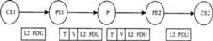
在转发过程中,报文的标记栈变化如图1所示,链路层报文L2 VPN在发送端的CE1中传送,发送端的运营商边界路由器(PE)1将链路层报文封装内层标记V和外层标记T后,将其传送给运营商路由器(P),P将外层标记T转换为T’后,再将其传送至接收端的PE2,然后PE2将去除封装的外层标记和内层标记,并将根据内层标记所对应的CE进行报文转发。During the forwarding process, the label stack of the message changes as shown in Figure 1. The link layer message L2 VPN is transmitted in CE1 at the sending end, and the carrier border router (PE) 1 at the sending end encapsulates the link layer message in the inner layer After marking V and the outer mark T, send it to the operator router (P), P converts the outer mark T into T', and then transmits it to PE2 at the receiving end, and then PE2 will remove the encapsulated outer mark and the inner label, and forward the message according to the CE corresponding to the inner label.
目前MPLS L2 VPN并没有形成统一的标准,比较常见的有KompellaMPLS L2 VPN和Martini MPLS L2 VPN两种。At present, there is no unified standard for MPLS L2 VPN. The more common ones are Kompella MPLS L2 VPN and Martini MPLS L2 VPN.
Kompella方式的L2VPN目前通过边界网关协议(MP-BGP)来实现,它不直接对CE与CE之间的连接进行操作,而是在整个SP网络中划分不同的VPN,在VPN内部对CE进行编号。当要建立两个CE之间的连接时,只需在PE上设置本地CE和远程CE的CE ID,并指定本地CE为这个连接分配的Circuit ID,如ATM的虚通路标识符/虚通道标识符(VPI/VCI)。在标记分配方面,Kompella方式L2VPN采取标记块的方式,一次为多个连接分配标记。用户可以指定一个本地CE的范围(range),CErange表明这个CE能与多少个CE建立连接。系统会一次为这个CE分配一个标记块,标记块的大小等于CE range。这种方式允许用户为VPN分配一些额外的标记。L2VPN in the Kompella mode is currently implemented through the Border Gateway Protocol (MP-BGP). It does not directly operate on the connection between CEs, but divides different VPNs in the entire SP network, and numbers CEs inside the VPNs. . When you want to establish a connection between two CEs, you only need to set the CE IDs of the local CE and the remote CE on the PE, and specify the Circuit ID allocated by the local CE for this connection, such as the virtual path identifier/virtual channel identifier of ATM character (VPI/VCI). In terms of label allocation, the Kompella L2VPN adopts a label block method to allocate labels for multiple connections at a time. The user can specify the range of a local CE, and the CErange indicates how many CEs this CE can establish connections with. The system will allocate one marker block for this CE at a time, and the size of the marker block is equal to CE range. This way allows the user to assign some additional flags to the VPN.
Martini方式的L2 VPN通过扩展LDP来实现,着重于解决“怎么在两个CE之间建立VC”的问题。它采用VC-TYPE+VC-ID来识别一个VC。VC-TYPE表明这个VC的类型是异步转移模式(ATM)、VLAN还是点到点(PPP);VC-ID则用于唯一标志一个VC。同一个VC-TYPE的所有VC中,其VC-ID必须在整个服务提供网络(SP)网络中唯一。连接两个CE的PE通过标签分发协议(LDP)交换VC标记,并通过VC-ID将对应的CE绑定起来。当连接两个PE的标签交换路径(LSP)建立成功,双方的标记交换和绑定完成后,一个VC就建立起来了,两个CE就可以通过这个VC传递二层数据。为了在PE之间交换VC标记,Martini草案对LDP进行了扩展,增加了VC FEC的转发等价类(FEC)类型。此外,由于交换VC标记的两个PE可能不是直接相连的,所以LDP必须使用remote peer来建立session,并在这个session上传递VC FEC和VC标记。L2 VPN in Martini mode is implemented by extending LDP, focusing on solving the problem of "how to establish a VC between two CEs". It uses VC-TYPE+VC-ID to identify a VC. VC-TYPE indicates whether the type of this VC is asynchronous transfer mode (ATM), VLAN or point-to-point (PPP); VC-ID is used to uniquely mark a VC. Among all VCs of the same VC-TYPE, its VC-ID must be unique in the entire service provider network (SP) network. PEs connected to two CEs exchange VC labels through Label Distribution Protocol (LDP), and bind corresponding CEs through VC-ID. When the label switching path (LSP) connecting two PEs is successfully established, and the label switching and binding between the two parties are completed, a VC is established, and two CEs can transmit Layer 2 data through this VC. In order to exchange VC labels between PEs, the Martini draft extends LDP by adding the forwarding equivalence class (FEC) type of VC FEC. In addition, since the two PEs exchanging VC labels may not be directly connected, LDP must use remote peer to establish a session, and transfer VC FEC and VC labels on this session.
对于MPLS L2 VPN,网络运营商负责提供给L2 VPN用户提供二层的连通性,不需要参与VPN用户的路由计算。在提供全连接的二层VPN时,和传统的二层VPN一样存在N方问题,每个VPN的CE到其它CE都需要在CE与PE之间分配一条连接。而且二层VPN的管理较为复杂,维护成本相对较高;且协议没有统一,互通性不能保证。For MPLS L2 VPN, the network operator is responsible for providing L2 VPN users with Layer 2 connectivity, and does not need to participate in the routing calculation of VPN users. When providing a full-connection Layer 2 VPN, there is an N-party problem like traditional Layer 2 VPNs. Each VPN CE needs to allocate a connection between CE and PE to other CEs. Moreover, the management of the Layer 2 VPN is relatively complicated, and the maintenance cost is relatively high; and the protocol is not unified, and the interoperability cannot be guaranteed.
发明内容Contents of the invention
有鉴于此,本发明的目的是提供一种建立虚拟电路的方法,使其提供基于VLAN交换的透明二层链路,管理简单,易于维护,成本低。In view of this, the object of the present invention is to provide a method for establishing a virtual circuit, which provides a transparent layer-2 link based on VLAN exchange, which is simple in management, easy in maintenance and low in cost.
一种建立虚拟电路的方法,是这样实现的。A method for establishing a virtual circuit is implemented in this way.
A.根据每个局域网用户的位置信息,将每个局域网用户进行编码,得到唯一标识每个局域网用户的用户编码;A. according to the location information of each local area network user, each local area network user is coded, obtains the user code that uniquely identifies each local area network user;
B.源局域网用户向目的局域网用户发送报文前,且源局域网用户与目的局域网用户之间未建立连接,源局域网用户对应的虚拟交换机根据目的局域网用户的用户编码,确定到达目的局域网用户所经过虚拟交换机的路径信息,然后将源虚拟交换机作为当前虚拟交换机,执行步骤C;B. Before the source LAN user sends a message to the destination LAN user, and there is no connection between the source LAN user and the destination LAN user, the virtual switch corresponding to the source LAN user determines the destination LAN user’s route according to the user code of the destination LAN user The path information of the virtual switch, and then use the source virtual switch as the current virtual switch, and perform step C;
C.当前虚拟交换机选择一个出端口和空闲的出虚拟局域网标识(VLANID),然后根据当前虚拟交换机的入端口、入VLAN ID和所选择的出端口、出VLAN ID建立与下一级虚拟交换机之间的交换表项;C. The current virtual switch selects an outgoing port and an idle virtual local area network identifier (VLANID), and then establishes a relationship with the next-level virtual switch according to the incoming port, incoming VLAN ID, selected outgoing port, and outgoing VLAN ID of the current virtual exchange. Exchange entries between
D.下一级虚拟交换机将当前虚拟交换机所选择的出VLAN ID和出端口作为入VLAN ID和入端口,然后判断自身是否为目的虚拟交换机,如果不是,将自身作为当前虚拟交换机,返回步骤C,否则,将目的局域网用户编码所对应的设备端口、VLAN ID作为出端口、出VLAN ID,建立与目的用户之间的交换表项,虚电路建立完成。D. The next-level virtual switch uses the outgoing VLAN ID and outgoing port selected by the current virtual switch as the incoming VLAN ID and incoming port, and then judges whether it is the destination virtual switch, if not, uses itself as the current virtual switch, and returns to step C , otherwise, use the device port and VLAN ID corresponding to the destination LAN user code as the outgoing port and outgoing VLAN ID to establish an exchange table entry with the destination user, and the virtual circuit is established.
所述用户编码是根据E.164编码规则或其扩展规则为每个LAN用户进行编码。The user encoding is performed for each LAN user according to the E.164 encoding rule or its extended rule.
步骤B所确定源局域网用户到目的局域网用户之间的路径上至少包括源虚拟交换机和目的虚拟交换机。The path determined in step B between the source LAN user and the destination LAN user includes at least the source virtual switch and the destination virtual switch.
在虚拟交换机中所建立的交换表项包括:入端口号、入VLAN ID、出端口号和出VLAN ID。The exchange table items established in the virtual switch include: ingress port number, ingress VLAN ID, egress port number and egress VLAN ID.
所述出端口和出VLAN ID是通过信令方式与步骤B所确定路径上当前虚拟交换机的下一级虚拟交换机协商完成。The outgoing port and the outgoing VLAN ID are negotiated with the next-level virtual switch of the current virtual switch on the path determined in step B through signaling.
所述出VLAN ID是从当前虚拟交换机相关设备端口中没有被使用的VLAN ID中任选一个。The outgoing VLAN ID is to choose one from the VLAN IDs that are not used in the relevant device ports of the current virtual switch.
所述出VLAN ID是通过信令通知步骤B所确定路径上当前虚拟交换机的下一级虚拟交换机。The outgoing VLAN ID is notified through signaling to the next-level virtual switch of the current virtual switch on the path determined in step B.
从上面的叙述可以看出,本发明具有如下优点和特点:As can be seen from the above narration, the present invention has the following advantages and characteristics:
1)通过VLAN交换机制可以突破4096个VLAN的限制,每一个端口可以有独立的4096个VLAN来区分用户,从而大大扩展了VLAN的数目,为大规模以太网接入提供了条件。1) The limit of 4096 VLANs can be broken through the VLAN switching mechanism, and each port can have 4096 independent VLANs to distinguish users, thereby greatly expanding the number of VLANs and providing conditions for large-scale Ethernet access.
2)通过VLAN交换可以有效抑制网络中的广播流量,避免广播风暴的发生;2) Through VLAN switching, broadcast traffic in the network can be effectively suppressed to avoid the occurrence of broadcast storms;
3)避免了MPLS L2 VPN的复杂配置和管理,实现易于维护的高效二层虚拟局域网络,由于可以直接在现有以太网设备上实现不需要使用新的硬件,而且也可以沿用现有的网管系统,所以可以降低部署的成本。3) It avoids the complicated configuration and management of MPLS L2 VPN, and realizes an efficient layer-2 virtual local area network that is easy to maintain. Since it can be implemented directly on existing Ethernet devices, no new hardware is needed, and the existing network management can also be used system, so the cost of deployment can be reduced.
4)由于不需要进行报文的重新封装,因而提高了数据的传送效率。4) Since there is no need to re-encapsulate the message, the efficiency of data transmission is improved.
附图说明Description of drawings
图1为现有技术中二层VPN标签栈处理示意图;Fig. 1 is a schematic diagram of Layer 2 VPN label stack processing in the prior art;
图2为实现本发明方法的流程示意图;Fig. 2 is the schematic flow chart realizing the method of the present invention;
图3为实现本发明的具体实施例的交换模式示意图;Fig. 3 is a schematic diagram of an exchange mode implementing a specific embodiment of the present invention;
图4为应用本发明实现VLAN接入模式下端口处理流程示意图;Fig. 4 is a schematic diagram of port processing flow under the application of the present invention to realize the VLAN access mode;
图5为应用本发明实现VLAN交换模式下端口处理流程示意图。Fig. 5 is a schematic diagram of port processing flow in the VLAN switching mode implemented by applying the present invention.
具体实施方式Detailed ways
本发明的核心内容是:对所有局域网(LAN)用户按照一定编号规则进行编码,然后根据源LAN用户编码和目的LAN用户编码,确定源LAN用户与目的LAN用户的一条路径,基于VLAN ID转换,在该路径上的所有虚拟交换机中通过手工或是信令的方式建立交换表项,从而实现源LAN用户与目的LAN用户建立LAN电路连接。The core content of the present invention is: all local area network (LAN) users are coded according to a certain numbering rule, then according to the source LAN user code and the destination LAN user code, determine a path between the source LAN user and the destination LAN user, based on the VLAN ID conversion, In all the virtual switches on the path, exchange entries are established manually or in a signaling manner, so that the source LAN user and the destination LAN user establish a LAN circuit connection.
如图2所示,实现本发明的方法包括以下步骤:As shown in Figure 2, realizing the method of the present invention comprises the following steps:
步骤201、根据每个局域网用户的位置信息,将每个局域网用户进行编码,得到唯一标识每个局域网用户的用户编码。Step 201 , according to the location information of each LAN user, code each LAN user to obtain a user code that uniquely identifies each LAN user.
步骤202、源局域网用户向目的局域网用户发送报文前,且源局域网用户与目的局域网用户之间未建立连接,源局域网用户对应的虚拟交换机根据目的局域网用户的用户编码,确定源局域网用户到目的局域网用户的路径。这里,源局域网用户对应的虚拟交换机可以根据人工设定目的局域网用户的用户编码,或通过控制信号提供而得到目的局域网用户的用户编码,然后再按照事先设定的网络拓扑或路由信息,确定下一级虚拟交换机;下一级虚拟交换机也是按照事先设定的网络拓扑或路由信息,确定其自身的下一级虚拟交换机,直至确定至目的用户。Step 202, before the source LAN user sends a message to the destination LAN user, and no connection is established between the source LAN user and the destination LAN user, the virtual switch corresponding to the source LAN user determines the source LAN user to the destination LAN user according to the user code of the destination LAN user. Path for LAN users. Here, the virtual switch corresponding to the source LAN user can manually set the user code of the destination LAN user, or obtain the user code of the destination LAN user through the control signal, and then determine the following according to the network topology or routing information set in advance. The first-level virtual switch; the lower-level virtual switch also determines its own lower-level virtual switch according to the preset network topology or routing information until the destination user is determined.
步骤203、源虚拟交换机选择一个端口和一个空闲的VLAN ID,作为报文的出端口和出VLAN ID,然后根据源用户VLAN ID和所述选择的出VLAN ID建立与下一级虚拟交换机间的VLAN交换表项,然后将所选择的出端口和出VLAN ID通知路径上的下一级交换机,下一级交换机再将该出VLAN ID作为入VLAN ID和入端口,并再选择一个出VLAN ID和出端口建立该交换机的VLAN交换表,直到目的交换机为止,从而形成从源用户到目的用户的VLAN交换链路。当然,出VLAN ID是从当前虚拟交换机相关设备端口中没有被使用的VLAN ID中任选一个,然后再通过信令通知下一级虚拟交换机。而且,当前虚拟交换机也可以通过信令方式与路径上的下一级虚拟交换机协商完成出端口和出VLAN ID。Step 203, the source virtual switch selects a port and an idle VLAN ID as the outgoing port and the outgoing VLAN ID of the message, and then establishes a connection with the next-level virtual switch according to the source user VLAN ID and the selected outgoing VLAN ID. VLAN exchange table items, and then notify the next-level switch on the path of the selected outbound port and outbound VLAN ID, and the next-level switch will use the outbound VLAN ID as the inbound VLAN ID and inbound port, and then select an outbound VLAN ID Establish the VLAN switching table of the switch with the outgoing port until the destination switch, thus forming a VLAN switching link from the source user to the destination user. Of course, the VLAN ID is to choose one from the unused VLAN IDs in the current virtual switch related device ports, and then notify the next-level virtual switch through signaling. Moreover, the current virtual switch can also negotiate with the next-level virtual switch on the path through signaling to complete the outgoing port and outgoing VLAN ID.
详细的说,在源交换机建立交换表项,该交换表项至少包括用户原来的VLAN ID与选择的出VLAN ID和出端口号;在目的交换机中建立交换表项,该表项包括入VLAN ID,与目的LAN用户的VLAN ID和出端口号。在源端的报文经过一系列的VLAN交换到达对端;对于源交换机和目的交换机之间的其它交换机的表项要包括入端口号、入VLAN ID和出端口号、出VLAN ID。这里,入VLAN ID也就是上一个交换机所选择的出VLAN ID。Said in detail, set up exchange table item in source switch, this exchange table item at least includes user's original VLAN ID and the outgoing VLAN ID of selection and the port number; , and the VLAN ID and outbound port number of the destination LAN user. The message at the source end reaches the opposite end through a series of VLAN exchanges; the entries of other switches between the source switch and the destination switch should include the ingress port number, ingress VLAN ID and egress port number, and egress VLAN ID. Here, the incoming VLAN ID is the outgoing VLAN ID selected by the previous switch.
所述虚电路连接就是从源用户组到目的用户组之间的VLAN交换机上的VLAN转发表,由此每个用户组之间可以通过手工设置为互通或隔离,从而在二层网络中实现虚拟局域网的功能。The virtual circuit connection is exactly the VLAN forwarding table on the VLAN switch between the source user group and the destination user group, so that each user group can be manually configured as intercommunication or isolation, thereby realizing a virtual network in the two-layer network. LAN functionality.
下面结合附图和具体实施例详细说明本发明的技术方案。The technical solution of the present invention will be described in detail below in conjunction with the accompanying drawings and specific embodiments.
本实施例采用E.164编码规则为每组LAN用户进行编码,在转发报文前,根据源LAN用户编码和目的LAN用户编码,通过手工或是信令的方式建立基于VLAN交换的电路连接。In this embodiment, the E.164 encoding rule is used to encode each group of LAN users. Before forwarding the message, according to the source LAN user code and the destination LAN user code, a circuit connection based on VLAN switching is established manually or by signaling.
如3图所示,该LAN包括VLAN交换机1、2、3,其中,每个VLAN交换机包括LAN VPN1用户和LAN VPN2用户,VLAN交换机1的LANVPN1用户的用户编码为1221,LAN VPN2用户的用户编码为1223;VLAN交换机2的LAN VPNl用户的用户编码为1226,LAN VPN2用户的用户编码为1225;VLAN交换机3的LAN VPN1用户的用户编码为1222,LAN VPN2用户的用户编码为1224;As shown in Figure 3, the LAN includes VLAN switches 1, 2, and 3, wherein each VLAN switch includes LAN VPN1 users and LAN VPN2 users, the user code of the LAN VPN1 user of VLAN switch 1 is 1221, and the user code of the LAN VPN2 user Be 1223; The user encoding of the LAN VPN1 user of VLAN switch 2 is 1226, and the user encoding of the LAN VPN2 user is 1225; The user encoding of the LAN VPN1 user of VLAN switch 3 is 1222, and the user encoding of the LAN VPN2 user is 1224;
当VLAN交换机1下接入的LAN VPN1用户需要访问位于VLAN交换机3下的LAN VPN1的用户时,VLAN交换机1首先查找LAN VPN1用户的报文,得到的目的用户编码1222,并通过查表得到到达用户编码1222要经过VLAN交换机1和VLAN交换机3;然后从所属VLAN中选择一个没有使用的VLAN ID,如VLAN ID21,再根据该VLAN ID在VLAN交换机1和VLAN交换机3上配置VLAN交换表项,VLAN交换机1中的表项包括源VLAN ID、出端口和VLAN ID21,VLAN交换机3中的交换表项包括入端口、VLAN ID21、出端口和目的VLAN ID,从而生成从1221到1222的虚电路。When a user of LAN VPN1 connected under VLAN switch 1 needs to access a user of LAN VPN1 under VLAN switch 3, VLAN switch 1 first searches the packets of LAN VPN1 users, obtains the destination user code 1222, and obtains the destination user code by looking up the table. User code 1222 will go through VLAN switch 1 and VLAN switch 3; then select an unused VLAN ID from the VLAN to which it belongs, such as VLAN ID21, and then configure VLAN exchange table items on VLAN switch 1 and VLAN switch 3 according to the VLAN ID, The entry in VLAN switch 1 includes source VLAN ID, outgoing port and VLAN ID21, and the exchange entry in VLAN switch 3 includes incoming port, VLAN ID21, outgoing port and purpose VLAN ID, thereby generating the virtual circuit from 1221 to 1222.
此后,基于上述虚电路的建立方法,VLAN交换机1将用户报文转发到对应的出端口,并将报文打上VLAN ID21在配置的相应端口转发到VLAN交换机3,然后在VLAN交换机3根据VLAN ID交换到VLAN2,由用户的LAN交换机在VLAN 2内查找对应的目的端口或VLAN ID转发到目的用户。Thereafter, based on the establishment method of the above-mentioned virtual circuit, VLAN switch 1 forwards the user message to the corresponding outgoing port, and stamps the message with VLAN ID 21 and forwards it to VLAN switch 3 at the corresponding port configured, and then forwards the message to VLAN switch 3 according to the VLAN ID in VLAN switch 3. Switch to VLAN2, and the user's LAN switch searches for the corresponding destination port or VLAN ID in VLAN 2 and forwards it to the destination user.
上述VLAN交换机制包括两种端口模式:一种为VLAN接入模式,另一种为VLAN交换模式。其中,VLAN接入模式用于用户与普通LAN交换机之间的连接,二层交换机作为VLAN二层虚拟局域网的接入端口,负责到达对端用户的链路选择和VPN用户隔离;而VLAN的交换模式用于虚拟局域网中不同节点之间的互联,提供快速简单的二层传送机制。The above VLAN switching mechanism includes two port modes: one is VLAN access mode, and the other is VLAN switching mode. Among them, the VLAN access mode is used for the connection between the user and the ordinary LAN switch, and the layer 2 switch is used as the access port of the VLAN layer 2 virtual local area network, and is responsible for the link selection of the peer user and the isolation of the VPN user; and the exchange of the VLAN The mode is used for the interconnection between different nodes in the virtual local area network, providing a fast and simple layer-2 transmission mechanism.
当端口处于VLAN接入模式时,需要对报文的目的Mac地址进行查找,得到对端的内部编码,然后根据内部编码表在两端设备的路径上生成对应的虚电路连接。When the port is in the VLAN access mode, it needs to search the destination Mac address of the message to obtain the internal code of the opposite end, and then generate the corresponding virtual circuit connection on the path of the devices at both ends according to the internal code table.
如图4所示,VLAN接入模式的端口处理流程如下:As shown in Figure 4, the port processing flow in VLAN access mode is as follows:
步骤401、二层交换机收到报文,根据该报文中校验码,判断该报文的正确性,如果正确,则执行步骤2,否则,丢弃该报文;
步骤402、判断该报文中是否含有目的MAC地址,如果有,则执行步骤3,否则,丢弃该报文;
步骤403、根据该报文的目的MAC地址,查找用户编码表,如果找到对应的用户编码,则执行步骤4,否则,丢弃该报文;
步骤404、根据目的用户编码得到到达对端的链路信息,确定转发路径,并在这条路径上所有交换设备中配置VLAN交换表项;Step 404, obtain the link information to reach the opposite end according to the target user code, determine the forwarding path, and configure the VLAN switching table entry in all switching devices on this path;
步骤405、该报文根据VLAN交换表项配置端口和指定的VLAN ID,将该报文转发至目的交换机。
而端口位于VLAN交换模式时,根据VLAN ID作为交换的依据选择出端口并修改报文的VLAN ID,并转发到交换机的对应出端口。When the port is in the VLAN switching mode, the outgoing port is selected according to the VLAN ID as the basis for switching, and the VLAN ID of the message is modified, and forwarded to the corresponding outgoing port of the switch.
如图5所示,VLAN交换模式的端口处理流程如下:As shown in Figure 5, the port processing flow in VLAN switching mode is as follows:
步骤501、目的交换机接收到报文后,根据该报文中校验码,判断该报文的正确性,如果正确,则执行步骤2,否则,丢弃该报文;
步骤502、根据VLAN ID查找VLAN转发表对应的目的VLAN ID,判断转发表中是否有对应的表项,如果有,则执行步骤3,否则,丢弃该报文;这里,所述的转发表就是前面提到的交换表项。
步骤503、根据转发表中对应的目的VLAN ID,将该报文转发到目的VLAN。
本发明的VLAN交换机制特点在于:建立一个基于端口的VLAN转发表表的内容包括入端口号,入VLAN ID和出端口号、出VLAN ID,从而报文可以不进行MAC地址表查找,直接匹配端口和VLAN ID快速查找出端口,替换原来的VLAN ID后实现报文的快速转发。在处理用户的报文时,V-Switch接入交换机首先要根据源MAC地址和目的MAC地址得到源用户编码和目的用户编码,然后通过信令的方式建立一条基于VLAN交换的虚电路,并为该用户指定要使用的VLAN ID,然后根据用户VLAN ID和生成的VLAN交换规则将报文转发到对端用户。这样,二层链路的保护可以通过由信令来动态修改网络中VLAN交换机的VLAN转发表来实现。The VLAN switching mechanism of the present invention is characterized in that: the content of establishing a port-based VLAN forwarding table includes an incoming port number, an incoming VLAN ID, an outgoing port number, and an outgoing VLAN ID, so that the message can be directly matched without searching the MAC address table Port and VLAN ID to quickly find out the port, and replace the original VLAN ID to realize fast forwarding of packets. When processing user packets, the V-Switch access switch must first obtain the source user code and destination user code according to the source MAC address and destination MAC address, and then establish a virtual circuit based on VLAN switching through signaling, and The user specifies the VLAN ID to be used, and then forwards the message to the peer user according to the user VLAN ID and the generated VLAN switching rules. In this way, the protection of the two-layer link can be realized by dynamically modifying the VLAN forwarding table of the VLAN switch in the network through signaling.
Claims (7)
Translated fromChinesePriority Applications (1)
| Application Number | Priority Date | Filing Date | Title |
|---|---|---|---|
| CNB031221505ACN100372321C (en) | 2003-04-17 | 2003-04-17 | A Method of Establishing Virtual Circuit |
Applications Claiming Priority (1)
| Application Number | Priority Date | Filing Date | Title |
|---|---|---|---|
| CNB031221505ACN100372321C (en) | 2003-04-17 | 2003-04-17 | A Method of Establishing Virtual Circuit |
Publications (2)
| Publication Number | Publication Date |
|---|---|
| CN1538682Atrue CN1538682A (en) | 2004-10-20 |
| CN100372321C CN100372321C (en) | 2008-02-27 |
Family
ID=34320962
Family Applications (1)
| Application Number | Title | Priority Date | Filing Date |
|---|---|---|---|
| CNB031221505AExpired - Fee RelatedCN100372321C (en) | 2003-04-17 | 2003-04-17 | A Method of Establishing Virtual Circuit |
Country Status (1)
| Country | Link |
|---|---|
| CN (1) | CN100372321C (en) |
Cited By (9)
| Publication number | Priority date | Publication date | Assignee | Title |
|---|---|---|---|---|
| WO2007009337A1 (en)* | 2005-07-15 | 2007-01-25 | Huawei Technologies Co. Ltd. | A method for implementing virtue-switch and the apparatus thereof |
| CN100382527C (en)* | 2005-06-03 | 2008-04-16 | 华为技术有限公司 | System and method for manually creating electrical circuits |
| CN100401721C (en)* | 2005-09-12 | 2008-07-09 | 中兴通讯股份有限公司 | A method for establishing an intelligent virtual switching link |
| CN100428729C (en)* | 2005-03-24 | 2008-10-22 | 杭州华三通信技术有限公司 | Method for realizing network interconnection between different QinQ apparatus |
| CN100433713C (en)* | 2005-07-15 | 2008-11-12 | 华为技术有限公司 | Virtual exchange access method, device and virtual exchange system based on IP |
| CN100459587C (en)* | 2006-11-02 | 2009-02-04 | 华为技术有限公司 | Method and equipment for realizing flexible QinQ |
| WO2010060373A1 (en)* | 2008-11-26 | 2010-06-03 | 华为技术有限公司 | Method, apparatus and system for establishing virtual local area network connection |
| CN101005439B (en)* | 2006-01-17 | 2010-06-23 | 中兴通讯股份有限公司 | Mutual access system and its method between VPN in VPLS network |
| CN105049361A (en)* | 2012-06-06 | 2015-11-11 | 瞻博网络公司 | Identifying likely faulty components in a distributed system |
Families Citing this family (1)
| Publication number | Priority date | Publication date | Assignee | Title |
|---|---|---|---|---|
| CN117749715A (en)* | 2022-09-14 | 2024-03-22 | 瑞昱半导体股份有限公司 | Network packet transmission device and network packet transmission method |
Family Cites Families (3)
| Publication number | Priority date | Publication date | Assignee | Title |
|---|---|---|---|---|
| US5953403A (en)* | 1997-01-31 | 1999-09-14 | Stentor Resource Centre, Inc. | Method for preventing call congestion on outgoing trunks of a local telephone exchange |
| US5995613A (en)* | 1997-10-02 | 1999-11-30 | At&T Corp | Method for establishing virtual private line for long distance carrier |
| IL144016A0 (en)* | 1998-12-29 | 2002-04-21 | Unisphere Solutions Inc | Method and apparatus for provisioning inter-machine trunks |
- 2003
- 2003-04-17CNCNB031221505Apatent/CN100372321C/ennot_activeExpired - Fee Related
Cited By (13)
| Publication number | Priority date | Publication date | Assignee | Title |
|---|---|---|---|---|
| CN100428729C (en)* | 2005-03-24 | 2008-10-22 | 杭州华三通信技术有限公司 | Method for realizing network interconnection between different QinQ apparatus |
| CN100382527C (en)* | 2005-06-03 | 2008-04-16 | 华为技术有限公司 | System and method for manually creating electrical circuits |
| US8665718B2 (en) | 2005-07-15 | 2014-03-04 | Huawei Technologies Co., Ltd | Method and device for implementing virtual-switch |
| CN100433713C (en)* | 2005-07-15 | 2008-11-12 | 华为技术有限公司 | Virtual exchange access method, device and virtual exchange system based on IP |
| US8045461B2 (en) | 2005-07-15 | 2011-10-25 | Huawei Technologies Co., Ltd. | Method and device for implementing virtual-switch |
| WO2007009337A1 (en)* | 2005-07-15 | 2007-01-25 | Huawei Technologies Co. Ltd. | A method for implementing virtue-switch and the apparatus thereof |
| CN100401721C (en)* | 2005-09-12 | 2008-07-09 | 中兴通讯股份有限公司 | A method for establishing an intelligent virtual switching link |
| CN101005439B (en)* | 2006-01-17 | 2010-06-23 | 中兴通讯股份有限公司 | Mutual access system and its method between VPN in VPLS network |
| CN100459587C (en)* | 2006-11-02 | 2009-02-04 | 华为技术有限公司 | Method and equipment for realizing flexible QinQ |
| WO2010060373A1 (en)* | 2008-11-26 | 2010-06-03 | 华为技术有限公司 | Method, apparatus and system for establishing virtual local area network connection |
| US9160567B2 (en) | 2008-11-26 | 2015-10-13 | Huawei Technologies Co., Ltd. | Method, apparatus, and system for establishing a virtual local area network connection |
| CN105049361A (en)* | 2012-06-06 | 2015-11-11 | 瞻博网络公司 | Identifying likely faulty components in a distributed system |
| CN105049361B (en)* | 2012-06-06 | 2017-05-10 | 瞻博网络公司 | Physical Path Determination for Virtual Network Packet Flows |
Also Published As
| Publication number | Publication date |
|---|---|
| CN100372321C (en) | 2008-02-27 |
Similar Documents
| Publication | Publication Date | Title |
|---|---|---|
| CN101521631B (en) | Treatment method, equipment and system for VPLS network messages | |
| CA2413570C (en) | Address resolution method for a virtual private network, and customer edge device for implementing the method | |
| US7266124B2 (en) | Method for setting up QoS supported bi-directional tunnel and distributing L2VPN membership information for L2VPN using extended LDP | |
| CN1266913C (en) | Tunneling through access network | |
| CN101277245B (en) | A method, system and device for implementing L2VPN cross-domain | |
| CN101155113A (en) | Multiplexing method and VLAN switching domain of a VLAN switching tunnel | |
| JP2000286853A (en) | Method and apparatus for routing packets | |
| CN1625176A (en) | Implementation method of edge-to-edge pseudowire emulation protocol | |
| CN1823505A (en) | Apparatus for connection-oriented transmission in packet-switched communication network | |
| CN1722698A (en) | Multi-protocol label switching virtual private network and its control and forwarding method | |
| JP2005341591A (en) | Virtual private network, multi-service provisioning platform and method | |
| CN1866919B (en) | Service switching method based on VLAN stack | |
| CN101047636A (en) | Method and system for end-to-end pseudo-line simulation virtual leased line access virtual special network | |
| CN1866923A (en) | Method and system for realizing binding interface edge-to-edge pseudo wire simulation service | |
| CN1472938A (en) | Method and device for carrying out terminal to terminal connection between RPR net and MPLS net | |
| WO2008040163A1 (en) | Ethernet frame transmitting method and ethernet infrastructure | |
| CN1913523A (en) | Method for implementing layer level virtual private exchange service | |
| CN1863133A (en) | Method and apparatus for transmitting message | |
| CN1691629A (en) | Method for Realizing Layer 2 Device Interconnection in Network Based on Resilient Packet Ring | |
| WO2008011818A1 (en) | Method of realizing hierarchy-virtual private lan service and network system | |
| WO2007134501A1 (en) | Method for interconnecting with nested backbone provider bridges and system thereof | |
| CN106330499A (en) | A transmission method and device for time-division multiplexing data, and network-side edge equipment | |
| CN100372321C (en) | A Method of Establishing Virtual Circuit | |
| CN1266887C (en) | Virtual switch for supplying virtual LAN service and method | |
| CN100337453C (en) | Method for implementing message forwarding along RPR ring and RPR network |
Legal Events
| Date | Code | Title | Description |
|---|---|---|---|
| C06 | Publication | ||
| PB01 | Publication | ||
| C10 | Entry into substantive examination | ||
| SE01 | Entry into force of request for substantive examination | ||
| C14 | Grant of patent or utility model | ||
| GR01 | Patent grant | ||
| CI03 | Correction of invention patent | Correction item:Claims Correct:Add claim Book Second False:Lack of claim Book Second Number:9 Volume:24 | |
| COR | Change of bibliographic data | Free format text:CORRECT: RIGHT-CLAIMING DOCUMENT; FROM: LACK OF RIGHT-CLAIMING DOCUMENT PAGE 2 TO: ADD RIGHT-CLAIMING DOCUMENT PAGE 2 | |
| CF01 | Termination of patent right due to non-payment of annual fee | Granted publication date:20080227 Termination date:20150417 | |
| EXPY | Termination of patent right or utility model |