CN1533290A - dilator - Google Patents
dilatorDownload PDFInfo
- Publication number
- CN1533290A CN1533290ACNA028074335ACN02807433ACN1533290ACN 1533290 ACN1533290 ACN 1533290ACN A028074335 ACNA028074335 ACN A028074335ACN 02807433 ACN02807433 ACN 02807433ACN 1533290 ACN1533290 ACN 1533290A
- Authority
- CN
- China
- Prior art keywords
- dilator
- wave
- roughly
- unit
- shaped
- Prior art date
- Legal status (The legal status is an assumption and is not a legal conclusion. Google has not performed a legal analysis and makes no representation as to the accuracy of the status listed.)
- Granted
Links
Images


Classifications
- A—HUMAN NECESSITIES
- A61—MEDICAL OR VETERINARY SCIENCE; HYGIENE
- A61F—FILTERS IMPLANTABLE INTO BLOOD VESSELS; PROSTHESES; DEVICES PROVIDING PATENCY TO, OR PREVENTING COLLAPSING OF, TUBULAR STRUCTURES OF THE BODY, e.g. STENTS; ORTHOPAEDIC, NURSING OR CONTRACEPTIVE DEVICES; FOMENTATION; TREATMENT OR PROTECTION OF EYES OR EARS; BANDAGES, DRESSINGS OR ABSORBENT PADS; FIRST-AID KITS
- A61F2/00—Filters implantable into blood vessels; Prostheses, i.e. artificial substitutes or replacements for parts of the body; Appliances for connecting them with the body; Devices providing patency to, or preventing collapsing of, tubular structures of the body, e.g. stents
- A61F2/82—Devices providing patency to, or preventing collapsing of, tubular structures of the body, e.g. stents
- A61F2/856—Single tubular stent with a side portal passage
- A—HUMAN NECESSITIES
- A61—MEDICAL OR VETERINARY SCIENCE; HYGIENE
- A61F—FILTERS IMPLANTABLE INTO BLOOD VESSELS; PROSTHESES; DEVICES PROVIDING PATENCY TO, OR PREVENTING COLLAPSING OF, TUBULAR STRUCTURES OF THE BODY, e.g. STENTS; ORTHOPAEDIC, NURSING OR CONTRACEPTIVE DEVICES; FOMENTATION; TREATMENT OR PROTECTION OF EYES OR EARS; BANDAGES, DRESSINGS OR ABSORBENT PADS; FIRST-AID KITS
- A61F2/00—Filters implantable into blood vessels; Prostheses, i.e. artificial substitutes or replacements for parts of the body; Appliances for connecting them with the body; Devices providing patency to, or preventing collapsing of, tubular structures of the body, e.g. stents
- A61F2/82—Devices providing patency to, or preventing collapsing of, tubular structures of the body, e.g. stents
- A—HUMAN NECESSITIES
- A61—MEDICAL OR VETERINARY SCIENCE; HYGIENE
- A61F—FILTERS IMPLANTABLE INTO BLOOD VESSELS; PROSTHESES; DEVICES PROVIDING PATENCY TO, OR PREVENTING COLLAPSING OF, TUBULAR STRUCTURES OF THE BODY, e.g. STENTS; ORTHOPAEDIC, NURSING OR CONTRACEPTIVE DEVICES; FOMENTATION; TREATMENT OR PROTECTION OF EYES OR EARS; BANDAGES, DRESSINGS OR ABSORBENT PADS; FIRST-AID KITS
- A61F2/00—Filters implantable into blood vessels; Prostheses, i.e. artificial substitutes or replacements for parts of the body; Appliances for connecting them with the body; Devices providing patency to, or preventing collapsing of, tubular structures of the body, e.g. stents
- A61F2/02—Prostheses implantable into the body
- A61F2/04—Hollow or tubular parts of organs, e.g. bladders, tracheae, bronchi or bile ducts
- A61F2/06—Blood vessels
- A61F2/07—Stent-grafts
- A—HUMAN NECESSITIES
- A61—MEDICAL OR VETERINARY SCIENCE; HYGIENE
- A61F—FILTERS IMPLANTABLE INTO BLOOD VESSELS; PROSTHESES; DEVICES PROVIDING PATENCY TO, OR PREVENTING COLLAPSING OF, TUBULAR STRUCTURES OF THE BODY, e.g. STENTS; ORTHOPAEDIC, NURSING OR CONTRACEPTIVE DEVICES; FOMENTATION; TREATMENT OR PROTECTION OF EYES OR EARS; BANDAGES, DRESSINGS OR ABSORBENT PADS; FIRST-AID KITS
- A61F2/00—Filters implantable into blood vessels; Prostheses, i.e. artificial substitutes or replacements for parts of the body; Appliances for connecting them with the body; Devices providing patency to, or preventing collapsing of, tubular structures of the body, e.g. stents
- A61F2/82—Devices providing patency to, or preventing collapsing of, tubular structures of the body, e.g. stents
- A61F2/86—Stents in a form characterised by the wire-like elements; Stents in the form characterised by a net-like or mesh-like structure
- A61F2/90—Stents in a form characterised by the wire-like elements; Stents in the form characterised by a net-like or mesh-like structure characterised by a net-like or mesh-like structure
- A61F2/91—Stents in a form characterised by the wire-like elements; Stents in the form characterised by a net-like or mesh-like structure characterised by a net-like or mesh-like structure made from perforated sheets or tubes, e.g. perforated by laser cuts or etched holes
- A61F2/915—Stents in a form characterised by the wire-like elements; Stents in the form characterised by a net-like or mesh-like structure characterised by a net-like or mesh-like structure made from perforated sheets or tubes, e.g. perforated by laser cuts or etched holes with bands having a meander structure, adjacent bands being connected to each other
- A—HUMAN NECESSITIES
- A61—MEDICAL OR VETERINARY SCIENCE; HYGIENE
- A61L—METHODS OR APPARATUS FOR STERILISING MATERIALS OR OBJECTS IN GENERAL; DISINFECTION, STERILISATION OR DEODORISATION OF AIR; CHEMICAL ASPECTS OF BANDAGES, DRESSINGS, ABSORBENT PADS OR SURGICAL ARTICLES; MATERIALS FOR BANDAGES, DRESSINGS, ABSORBENT PADS OR SURGICAL ARTICLES
- A61L27/00—Materials for grafts or prostheses or for coating grafts or prostheses
- A61L27/50—Materials characterised by their function or physical properties, e.g. injectable or lubricating compositions, shape-memory materials, surface modified materials
- A61L27/56—Porous materials, e.g. foams or sponges
- A—HUMAN NECESSITIES
- A61—MEDICAL OR VETERINARY SCIENCE; HYGIENE
- A61F—FILTERS IMPLANTABLE INTO BLOOD VESSELS; PROSTHESES; DEVICES PROVIDING PATENCY TO, OR PREVENTING COLLAPSING OF, TUBULAR STRUCTURES OF THE BODY, e.g. STENTS; ORTHOPAEDIC, NURSING OR CONTRACEPTIVE DEVICES; FOMENTATION; TREATMENT OR PROTECTION OF EYES OR EARS; BANDAGES, DRESSINGS OR ABSORBENT PADS; FIRST-AID KITS
- A61F2/00—Filters implantable into blood vessels; Prostheses, i.e. artificial substitutes or replacements for parts of the body; Appliances for connecting them with the body; Devices providing patency to, or preventing collapsing of, tubular structures of the body, e.g. stents
- A61F2/02—Prostheses implantable into the body
- A61F2/04—Hollow or tubular parts of organs, e.g. bladders, tracheae, bronchi or bile ducts
- A61F2/06—Blood vessels
- A61F2002/065—Y-shaped blood vessels
- A—HUMAN NECESSITIES
- A61—MEDICAL OR VETERINARY SCIENCE; HYGIENE
- A61F—FILTERS IMPLANTABLE INTO BLOOD VESSELS; PROSTHESES; DEVICES PROVIDING PATENCY TO, OR PREVENTING COLLAPSING OF, TUBULAR STRUCTURES OF THE BODY, e.g. STENTS; ORTHOPAEDIC, NURSING OR CONTRACEPTIVE DEVICES; FOMENTATION; TREATMENT OR PROTECTION OF EYES OR EARS; BANDAGES, DRESSINGS OR ABSORBENT PADS; FIRST-AID KITS
- A61F2/00—Filters implantable into blood vessels; Prostheses, i.e. artificial substitutes or replacements for parts of the body; Appliances for connecting them with the body; Devices providing patency to, or preventing collapsing of, tubular structures of the body, e.g. stents
- A61F2/82—Devices providing patency to, or preventing collapsing of, tubular structures of the body, e.g. stents
- A61F2002/821—Ostial stents
- A—HUMAN NECESSITIES
- A61—MEDICAL OR VETERINARY SCIENCE; HYGIENE
- A61F—FILTERS IMPLANTABLE INTO BLOOD VESSELS; PROSTHESES; DEVICES PROVIDING PATENCY TO, OR PREVENTING COLLAPSING OF, TUBULAR STRUCTURES OF THE BODY, e.g. STENTS; ORTHOPAEDIC, NURSING OR CONTRACEPTIVE DEVICES; FOMENTATION; TREATMENT OR PROTECTION OF EYES OR EARS; BANDAGES, DRESSINGS OR ABSORBENT PADS; FIRST-AID KITS
- A61F2/00—Filters implantable into blood vessels; Prostheses, i.e. artificial substitutes or replacements for parts of the body; Appliances for connecting them with the body; Devices providing patency to, or preventing collapsing of, tubular structures of the body, e.g. stents
- A61F2/82—Devices providing patency to, or preventing collapsing of, tubular structures of the body, e.g. stents
- A61F2/86—Stents in a form characterised by the wire-like elements; Stents in the form characterised by a net-like or mesh-like structure
- A61F2/90—Stents in a form characterised by the wire-like elements; Stents in the form characterised by a net-like or mesh-like structure characterised by a net-like or mesh-like structure
- A61F2/91—Stents in a form characterised by the wire-like elements; Stents in the form characterised by a net-like or mesh-like structure characterised by a net-like or mesh-like structure made from perforated sheets or tubes, e.g. perforated by laser cuts or etched holes
- A61F2/915—Stents in a form characterised by the wire-like elements; Stents in the form characterised by a net-like or mesh-like structure characterised by a net-like or mesh-like structure made from perforated sheets or tubes, e.g. perforated by laser cuts or etched holes with bands having a meander structure, adjacent bands being connected to each other
- A61F2002/91525—Stents in a form characterised by the wire-like elements; Stents in the form characterised by a net-like or mesh-like structure characterised by a net-like or mesh-like structure made from perforated sheets or tubes, e.g. perforated by laser cuts or etched holes with bands having a meander structure, adjacent bands being connected to each other within the whole structure different bands showing different meander characteristics, e.g. frequency or amplitude
- A—HUMAN NECESSITIES
- A61—MEDICAL OR VETERINARY SCIENCE; HYGIENE
- A61F—FILTERS IMPLANTABLE INTO BLOOD VESSELS; PROSTHESES; DEVICES PROVIDING PATENCY TO, OR PREVENTING COLLAPSING OF, TUBULAR STRUCTURES OF THE BODY, e.g. STENTS; ORTHOPAEDIC, NURSING OR CONTRACEPTIVE DEVICES; FOMENTATION; TREATMENT OR PROTECTION OF EYES OR EARS; BANDAGES, DRESSINGS OR ABSORBENT PADS; FIRST-AID KITS
- A61F2/00—Filters implantable into blood vessels; Prostheses, i.e. artificial substitutes or replacements for parts of the body; Appliances for connecting them with the body; Devices providing patency to, or preventing collapsing of, tubular structures of the body, e.g. stents
- A61F2/82—Devices providing patency to, or preventing collapsing of, tubular structures of the body, e.g. stents
- A61F2/86—Stents in a form characterised by the wire-like elements; Stents in the form characterised by a net-like or mesh-like structure
- A61F2/90—Stents in a form characterised by the wire-like elements; Stents in the form characterised by a net-like or mesh-like structure characterised by a net-like or mesh-like structure
- A61F2/91—Stents in a form characterised by the wire-like elements; Stents in the form characterised by a net-like or mesh-like structure characterised by a net-like or mesh-like structure made from perforated sheets or tubes, e.g. perforated by laser cuts or etched holes
- A61F2/915—Stents in a form characterised by the wire-like elements; Stents in the form characterised by a net-like or mesh-like structure characterised by a net-like or mesh-like structure made from perforated sheets or tubes, e.g. perforated by laser cuts or etched holes with bands having a meander structure, adjacent bands being connected to each other
- A61F2002/91533—Stents in a form characterised by the wire-like elements; Stents in the form characterised by a net-like or mesh-like structure characterised by a net-like or mesh-like structure made from perforated sheets or tubes, e.g. perforated by laser cuts or etched holes with bands having a meander structure, adjacent bands being connected to each other characterised by the phase between adjacent bands
- A—HUMAN NECESSITIES
- A61—MEDICAL OR VETERINARY SCIENCE; HYGIENE
- A61F—FILTERS IMPLANTABLE INTO BLOOD VESSELS; PROSTHESES; DEVICES PROVIDING PATENCY TO, OR PREVENTING COLLAPSING OF, TUBULAR STRUCTURES OF THE BODY, e.g. STENTS; ORTHOPAEDIC, NURSING OR CONTRACEPTIVE DEVICES; FOMENTATION; TREATMENT OR PROTECTION OF EYES OR EARS; BANDAGES, DRESSINGS OR ABSORBENT PADS; FIRST-AID KITS
- A61F2/00—Filters implantable into blood vessels; Prostheses, i.e. artificial substitutes or replacements for parts of the body; Appliances for connecting them with the body; Devices providing patency to, or preventing collapsing of, tubular structures of the body, e.g. stents
- A61F2/82—Devices providing patency to, or preventing collapsing of, tubular structures of the body, e.g. stents
- A61F2/86—Stents in a form characterised by the wire-like elements; Stents in the form characterised by a net-like or mesh-like structure
- A61F2/90—Stents in a form characterised by the wire-like elements; Stents in the form characterised by a net-like or mesh-like structure characterised by a net-like or mesh-like structure
- A61F2/91—Stents in a form characterised by the wire-like elements; Stents in the form characterised by a net-like or mesh-like structure characterised by a net-like or mesh-like structure made from perforated sheets or tubes, e.g. perforated by laser cuts or etched holes
- A61F2/915—Stents in a form characterised by the wire-like elements; Stents in the form characterised by a net-like or mesh-like structure characterised by a net-like or mesh-like structure made from perforated sheets or tubes, e.g. perforated by laser cuts or etched holes with bands having a meander structure, adjacent bands being connected to each other
- A61F2002/9155—Adjacent bands being connected to each other
- A61F2002/91558—Adjacent bands being connected to each other connected peak to peak
- A—HUMAN NECESSITIES
- A61—MEDICAL OR VETERINARY SCIENCE; HYGIENE
- A61F—FILTERS IMPLANTABLE INTO BLOOD VESSELS; PROSTHESES; DEVICES PROVIDING PATENCY TO, OR PREVENTING COLLAPSING OF, TUBULAR STRUCTURES OF THE BODY, e.g. STENTS; ORTHOPAEDIC, NURSING OR CONTRACEPTIVE DEVICES; FOMENTATION; TREATMENT OR PROTECTION OF EYES OR EARS; BANDAGES, DRESSINGS OR ABSORBENT PADS; FIRST-AID KITS
- A61F2230/00—Geometry of prostheses classified in groups A61F2/00 - A61F2/26 or A61F2/82 or A61F9/00 or A61F11/00 or subgroups thereof
- A61F2230/0002—Two-dimensional shapes, e.g. cross-sections
- A61F2230/0028—Shapes in the form of latin or greek characters
- A61F2230/0054—V-shaped
Landscapes
- Health & Medical Sciences (AREA)
- Engineering & Computer Science (AREA)
- Biomedical Technology (AREA)
- General Health & Medical Sciences (AREA)
- Veterinary Medicine (AREA)
- Oral & Maxillofacial Surgery (AREA)
- Transplantation (AREA)
- Public Health (AREA)
- Life Sciences & Earth Sciences (AREA)
- Animal Behavior & Ethology (AREA)
- Heart & Thoracic Surgery (AREA)
- Vascular Medicine (AREA)
- Cardiology (AREA)
- Physics & Mathematics (AREA)
- Optics & Photonics (AREA)
- Chemical & Material Sciences (AREA)
- Dermatology (AREA)
- Dispersion Chemistry (AREA)
- Medicinal Chemistry (AREA)
- Epidemiology (AREA)
- Gastroenterology & Hepatology (AREA)
- Pulmonology (AREA)
- Media Introduction/Drainage Providing Device (AREA)
- Prostheses (AREA)
Abstract
Description
Translated fromChinese技术领域technical field
本发明涉及放置或移植在体内的管组织用的扩张器,例如在把血管的狭窄或闭塞部位扩张后为了防止该部位的再次狭窄放置或移植在血管内用的扩张器。The present invention relates to a dilator to be placed or implanted in a vessel tissue in the body, for example, a dilator to be placed or implanted in a blood vessel in order to prevent restenosis of the narrowed or occluded part of the blood vessel after the dilation.
背景技术Background technique
所谓扩张器是指为了治疗由血管或其他生体内管腔狭窄或闭塞引起的各种病患而把狭窄或闭塞部位扩张,为维持其管腔尺寸在那里放置的医疗用具。其中有由一根线状金属或高分子材料构成的线圈状的,有把金属管用激光切下加工的,有把线状构件用激光焊接组装的,有把多根线状金属编织作成的等。这些在特开平8-332230号中被公开。The so-called dilator refers to a medical device placed there to maintain the size of the lumen to expand the stenosis or occlusion in order to treat various diseases caused by the stenosis or occlusion of blood vessels or other lumens in the living body. Among them, there are coils made of a single linear metal or polymer material, metal tubes are cut and processed by laser, linear components are assembled by laser welding, and multiple linear metals are braided. . These are disclosed in JP-A-8-332230.
这些分成通过安装了扩张器的支架而被扩张的和通过从外部把抑制扩张的构件去掉而自己扩张的。这其中用支架扩张的扩张器根据想扩展的管状组织的状态和扩张器的机械强度调整扩张压使用。These are divided into those that are expanded by a stent fitted with a dilator and those that are self-expanding by externally removing a member that inhibits expansion. Among them, the expander expanded with a stent is used by adjusting the expansion pressure according to the state of the tubular tissue to be expanded and the mechanical strength of the expander.
近年,特别在心脏和颈动脉的血管形成术这些扩张器广泛使用。把该扩张器以收缩进支架导管(扩张器供给导管)的状态使其固定(预安装)作为制品。实际使用时扩张器以预安装状态把扩张器供给导管引导到血管狭窄部,通过扩张支架把扩张器扩张,放置在血管狭窄部。然后把扩张器供给导管拔出体外。关于该预安装在特开2000-189520等中被公开。In recent years, these dilators have been widely used especially in angioplasty of the heart and carotid arteries. This dilator is fixed (preinstalled) in a state of being shrunk into a stent catheter (dilator supply catheter) as a product. In actual use, the dilator guides the dilator supply catheter to the narrowed part of the blood vessel in a pre-installed state, expands the dilator through the expansion stent, and places it in the narrowed part of the blood vessel. The dilator feeding catheter is then pulled out of the body. This preinstallation is disclosed in Japanese Unexamined Patent Publication No. 2000-189520 and the like.
构成扩张器的最小单位线状单元被称为支柱。扩张器的设计根据该支柱形成的图形被大体分类成敞开型和闭合型这两类。The smallest linear unit constituting the dilator is called a strut. The design of the dilator is roughly classified into two types, an open type and a closed type, according to the pattern formed by the struts.
如专利第2645203号所公开的,敞开型把波(正弦波)状在周方向重复的一段沿轴向重复多段,把其中间用每一周1~3处的连结段连接。As disclosed in Patent No. 2645203, the open type repeats a section of wave (sine wave) shape in the circumferential direction to multiple sections in the axial direction, and connects them with 1 to 3 connecting sections per week.
另一方面如特公平4-6377号、特开平10-137345号、特表平10-503676号等所公开的,闭合型用支柱形成(闭合成)多角形,并使该多角形的边共有,在圆周向、轴向重复该多角形。如上述公开专利所示,通过在该多角形中局部设有被称为柔软连结件的小弯曲部或波形的部分来提高扩张器的柔软性。On the other hand, as disclosed in JP 4-6377, JP 10-137345, JP 10-503676, etc., the closed type uses pillars to form (close) a polygon, and the sides of the polygon share , repeating the polygon in the circumferential and axial directions. As shown in the above-mentioned patent publication, the flexibility of the dilator is improved by partially providing a small curved portion or a wave-shaped portion called a flexible link in the polygon.
特公平4-6377号记载了扩张后形成连续结构单元的菱形形状的扩张器。该扩张器具有抵抗血管收缩力非常大的优点。但该扩张器非扩张时在轴向上柔软性欠缺,所以向弯曲的血管插入非常困难,且还有可能损伤血管内部。而且扩张后在轴向上也缺少柔软性,所以放置在弯曲的血管内时有对血管给予过度刺激,促进其再狭窄的问题。另外,在扩张时有扩张器轴向长度收缩,错开血管的狭窄整体扩张,定位难等的问题。Japanese Patent Publication No. 4-6377 describes a diamond-shaped dilator that forms a continuous structural unit after expansion. The dilator has the advantage of being very resistant to vasoconstriction forces. However, since this dilator lacks flexibility in the axial direction when it is not expanded, it is very difficult to insert into a curved blood vessel, and there is a possibility of damaging the inside of the blood vessel. In addition, it lacks flexibility in the axial direction after dilation, so when it is placed in a curved blood vessel, there is a problem of overstimulating the blood vessel and promoting restenosis. In addition, there are problems such as shrinkage of the axial length of the dilator during dilation, staggered stenosis of blood vessels and overall expansion, and difficulty in positioning.
特公平7-24688号记载了把金属丝变形成锯齿状、再把它螺旋状地卷成圆筒形状的扩张器。该扩张器在轴向富有柔软性,向弯曲的血管的插入性优良。但抵抗血管收缩力非常小,有容易受血管收缩压力而收缩的问题。Japanese Patent Publication No. 7-24688 describes a dilator in which a metal wire is deformed into a zigzag shape, and then spirally wound into a cylindrical shape. This dilator is flexible in the axial direction and has excellent insertability into curved blood vessels. However, the resistance to vasoconstriction is very small, and there is a problem that it is easily contracted by vasoconstriction pressure.
现在的扩张器一般在扩张到目标直径时,使扩张器的支柱均匀扩张困难,存在即使在同一圆周内也容易形成有部分扩张大的部分和不太扩张的部分的问题。当出现这种不均匀的扩张时,有时管状组织的内皮组织从支柱开大的部分突进很多,成为再狭窄的原因。不均匀扩张严重时,有时还不能维持断面的真圆。为解决该问题,在安装扩张器支架的折叠方法上想了办法。但即使这样,使其充分均匀扩张也是困难的。其他方法中,试验了在支架表面粘上容易均匀扩张的构件等技术。但支架的外形变大,产生了把扩张器供给到目标部位变困难的问题。Generally, when the current dilators are expanded to the target diameter, it is difficult to uniformly expand the struts of the dilator, and there is a problem that parts that are partially expanded and parts that are not very expanded are likely to be formed even within the same circumference. When such uneven expansion occurs, the endothelial tissue of the tubular tissue may protrude a lot from the enlarged part of the pillar, which may cause restenosis. When the uneven expansion is severe, sometimes the true circle of the section cannot be maintained. In order to solve this problem, a method has been devised on the folding method for installing the dilator bracket. But even then, it is difficult to make it expand uniformly enough. Among other methods, techniques such as sticking a member that is easy to expand uniformly on the surface of the stent have been tested. However, the shape of the stent becomes larger, and there arises a problem that it becomes difficult to supply the dilator to the target site.
另外,用支架扩张的扩张器的大半在扩张时扩张器两端部直径翘曲成比中央部大,有局部过扩张的问题。当扩张器两端部过扩张时,有时该部分刺激管状组织的内皮细胞,成为由细胞增殖而再狭窄的原因。In addition, most of the dilators expanded with a stent have a problem of local overexpansion due to warping of diameters at both end portions of the dilator compared to the central portion during expansion. When both ends of the dilator are over-expanded, these parts may stimulate the endothelial cells of the tubular tissue and cause restenosis due to cell proliferation.
另外,现在的扩张器一般在扩张时通过扩张器支柱间形成的空隙部分大,管状组织的内皮细胞从该空隙部分突进很多,有时成为再狭窄的原因。这是由于构成扩张器基本单元的尺寸大,但为了把它变小就需要减小支柱的宽度,但也存在这样得到的径向力即承受从外周受到的径向应力小的问题。In addition, the current dilator generally has a large gap formed between the dilator struts during dilation, and endothelial cells of tubular tissue protrude a lot from the gap, which may cause restenosis. This is because the size of the basic unit constituting the dilator is large, but in order to make it smaller, the width of the strut needs to be reduced, but there is also a problem that the radial force obtained in this way, that is, the radial stress received from the outer periphery is small.
接着在下面说明敞开型和闭合型扩张器的优点和缺点。Next, the advantages and disadvantages of open and closed dilators are described below.
敞开型首要的优点是富有轴向的柔软性,向弯曲的血管的插入性优良。还有可以向分岔血管插入Y扩张器的技术也是大优点。Y扩张器或Y扩张技术是在分岔部血管有狭窄时在主血管和侧枝血管这两面各放置一个扩张器的技术。最近,技术例增加起来,成为对扩张器要求的性能内最重要的一条。关于该技术在医学书院出版的「PTCA技术 光藤和明」的22中分岔部扩张器(203页)中记载了详细情况。即如图45所示,第一扩张器621放置在从主血管1的近位部623到主血管601的远位部624,而把第二扩张器622放置在从主血管601的近位部623到侧枝602,在主血管601的近位部623两个扩张器重叠。该技术最初把第一扩张器放置在主血管,然后,通过该第一扩张器支柱间的开口部(空隙)把预安装有第二扩张器的扩张器供给导管供向侧枝,在过渡支架定位到主血管近位部、第一扩张器支柱问的开口部(空隙)、侧枝入口部的状态扩张支架。这样,扩张器就过渡放置在主血管近位部、第一扩张器支柱间的开口部(空隙)和侧枝入口部。The main advantage of the open type is that it is rich in flexibility in the axial direction and has excellent insertability into curved blood vessels. It is also a great advantage that the technique of inserting a Y dilator into a bifurcated vessel is also possible. The Y dilator or Y dilation technique is a technique in which a dilator is placed on each side of the main vessel and the side branch vessel when the bifurcation vessel is narrowed. Recently, technical examples have increased and become the most important among the performance requirements for dilators. The details of this technique are described in 22 bifurcation dilators (page 203) of "PTCA Technique Kazuaki Mitsuto" published by the Medical Academy. That is, as shown in FIG. 45, the first dilator 621 is placed from the proximal part 623 of the main blood vessel 1 to the distal part 624 of the main blood vessel 601, and the second dilator 622 is placed from the proximal part of the main blood vessel 601. 623 to the side branch 602, the two dilators overlap at the proximal portion 623 of the main vessel 601. In this technique, the first dilator is initially placed in the main vessel, and then the dilator supply catheter with the second dilator pre-installed is supplied to the side branches through the opening (gap) between the struts of the first dilator. The stent is expanded to the proximal part of the main blood vessel, the opening part (space) between the first dilator struts, and the entrance part of the side branch. In this way, the dilator is transitionally placed at the proximal part of the main blood vessel, the opening (space) between the first dilator struts and the side branch entrance.
这是因为敞开型的连接段在每一周只存在1~3处,通过支柱间形成的空隙部分的周围长度长,因此当在支柱间的空隙部分通过扩张器供给导管的支架扩张时,该支柱变形,在支柱间形成的空隙部分同时变形,开口面积变大,从而能进入侧枝的缘故。This is because there are only 1 to 3 open-type connecting sections per week, and the surrounding length of the gap formed between the struts is long. Deformation, the gap formed between the pillars deforms at the same time, and the opening area becomes larger, so that side branches can enter.
但作为缺点是径向力非常小,有因血管要收缩的压力而容易收缩的问题。而且由于上述的在支柱间形成的空隙部分周围部的长度大,所以把扩张器扩张放置在弯曲血管时有时位于弯曲外侧的空隙部分开口大,血管的内皮组织向扩张器内突进很多,成为再狭窄的原因。表现该空隙部分的开口面积如何小的性能叫做架构(scaffold)性。However, the disadvantage is that the radial force is very small, and there is a problem that the blood vessel is easily contracted by the pressure of the contraction. And because the length of the surrounding part of the space part formed between the above-mentioned struts is large, so when the dilator is expanded and placed on the curved blood vessel, the opening of the space part outside the bend is sometimes large, and the endothelial tissue of the blood vessel protrudes a lot into the dilator, which becomes a new structure. cause of narrowing. The performance showing how small the opening area of the void portion is is called the scaffold property.
而闭合型的优点是支柱构成多角形,该多角形在共有边的同时并在周方向、轴方向上重复的缘故,有上述的径向力非常大的优点。由于同时存在周长被限定的多角形,所以即使被配置在弯曲的血管内,成为位于弯曲外侧空隙部分的多角形也不以大于其形状的面积开口,所以上述的架构性良好。On the other hand, the advantage of the closed type is that the pillars form a polygon, and because the polygon shares a side and repeats in the circumferential direction and the axial direction, there is an advantage that the above-mentioned radial force is very large. Since there are polygons with a limited perimeter, even if they are arranged in a curved blood vessel, the polygons located in the space outside the curvature do not open with an area larger than the shape, so the above-mentioned structural properties are good.
但有不能进行向上述分岔血管移植Y扩张器的缺点。即进行移植Y扩张器时,通过成为闭合型支柱间空隙的多角形向侧枝血管的方向即使使别的扩张器供给导管的支架通过、扩张,也由于该多角形周长被限定而多角形不能更大地开口,所以有不能向侧枝进入的缺点。为解决它也考虑了增加多角形的面积,但这样作与敞开型一样要牺牲架构(scaffold)性。However, there is a disadvantage that the Y dilator cannot be implanted into the above-mentioned bifurcated blood vessel. That is, when the Y dilator is transplanted, even if the stent of the other dilator supply catheter is passed and expanded through the polygon forming the closed strut gap toward the side branch vessel, the polygon cannot be expanded because the perimeter of the polygon is limited. Since the opening is large, there is a disadvantage that it cannot enter side branches. In order to solve this problem, it is also considered to increase the area of the polygon, but this will sacrifice the structure (scaffold) like the open type.
发明内容Contents of the invention
为达到所述目的,本发明第一方面在于提供一种扩张器,其在扩张器扩张前轴向柔软,且在扩张器扩张时扩张器的轴向长度不收缩,在扩张后抵抗血管收缩力非常大,而且能使扩张器的支柱均匀扩张,且在扩张时不产生扩张器的两端部的径翘曲成比中央部大的问题。To achieve the stated purpose, the first aspect of the present invention is to provide a dilator, which is soft in the axial direction before the dilator expands, and the axial length of the dilator does not shrink when the dilator expands, and resists the vasoconstrictive force after dilating It is very large, and can evenly expand the struts of the dilator, and there is no problem that the diameters of the two ends of the dilator are warped to be larger than the central part during expansion.
本发明提供有下列特征的扩张器,其形成大致管状体,且能向大致管状体的半径方向外侧伸长。所述扩张器101由在圆周方向能伸长的大致波形结构单元102和在轴向能伸长的大致波形结构单元103构成,多个在所述圆周方向能伸长的大致波形结构单元102相互不直接连接地配置在扩张器101的大致圆周方向上,同时多个在所述轴向能伸长的大致波形结构单元103相互不直接连接地配置在扩张器101的大致圆周方向上,它们相互在扩张器轴向上周期性地交替连续而构成。The present invention provides a dilator characterized in that it is formed into a substantially tubular body and can be extended outward in the radial direction of the substantially tubular body. The
本发明还提供扩张器,其形成大致管状体,且能向大致管状体的半径方向外侧伸长。所述扩张器101由在圆周方向能伸长的大致波形结构单元102和轴向能伸长的大致波形结构单元103构成;通过所述在圆周方向能伸长的大致波形结构单元102一端的连接部127与所述在轴向能伸长的大致波形结构单元103一端的连接部131连接,所述在轴向能伸长的大致波形结构单元103另一端的连接部139与另一个在圆周方向能伸长的大致波形结构单元102的与所述127相反侧一端的连接部121连接,使得在圆周方向能伸长的所述大致波形结构单元102和轴向能伸长的大致波形结构单元103周期性地连续。另外,通过所述在圆周方向能伸长的大致波形结构单元102的峰或谷的凸部连接部123与所述轴向能伸长的大致波形结构单元103一端的连接部131连接,所述轴向能伸长的大致波形结构单元103另一端的连接部139与另一个在圆周方向能伸长的大致波形结构单元102的位于与所述相反侧的峰或谷的凸部连接部125连接,使得在所述圆周方向能伸长的所述大致波形结构单元102和轴向能伸长的大致波形结构单元103被周期性地连续形成。The present invention also provides a dilator which is formed into a substantially tubular body and can be extended outward in the radial direction of the substantially tubular body. The
所述扩张器101通过同时具有在扩张器的圆周方向能伸长的单元和轴向能伸长的单元,能减少扩张时扩张器的轴向收缩,且通过恰当配置大致波形结构单元能轴向柔软,扩张时均匀扩张,对血管的收缩力表现出大的抵抗力,完成了上述课题。The
本发明提供了特征是仅扩张器101的轴向两端沿扩张器的圆周配列形成直接连续的多个在所述圆周方向能伸长的大致波形结构单元102的上述扩张器。这样,扩张器两端与扩张器中央部分相比抵抗血管收缩的力大,且减少了扩张时扩张器两端部径的翘曲成比中央部大,完成了上述课题。The present invention provides the above-mentioned dilator characterized in that only the axial ends of the
本发明提供形成大致管状体,且能向大致管状体的半径方向外侧伸长的扩张器201,所述扩张器由在圆周方向能伸长的大致波形结构单元202和圆周方向能伸长的大致波形结构单元203和在轴向能伸长的大致波形结构单元204构成;多个在所述圆周方向能伸长的大致波形结构单元202相互不直接连接地配置在扩张器的大致圆周方向上,同时在多个所述圆周方向能伸长的大致波形结构单元203相互不直接连接地配置在扩张器的大致圆周方向上,并且多个在所述轴向能伸长的大致波形结构单元204相互不直接连接地配置在扩张器的大致圆周方向上,它们相互在扩张器轴向上周期性地交替连续而构成。The present invention provides a
本发明还提供扩张器,其形成大致管状体,且能向大致管状体的半径方向外侧伸长的扩张器,所述扩张器201由在圆周方向能伸长的大致波形结构单元202和在所述扩张器在圆周方向能伸长的大致波形结构单元203和在轴向能伸长的大致波形结构单元204构成;通过在所述圆周方向能伸长的大致波形结构单元202一端的连接部227与在所述轴向能伸长的大致波形结构单元204一端的连接部241连接,在所述轴向能伸长的大致波形结构单元204另一端的连接部249与在所述圆周方向能伸长的大致波形结构单元203的峰或谷的凸部连接部233连接,且所述在圆周方向能伸长的大致波形结构单元203的存在于与所述连接部233相反侧的峰或谷的凸部连接部235与所述另一个在轴向能伸长的大致波形结构单元204一端的连接部241连接,所述在轴向能伸长的大致波形结构单元204另一端的连接部249与在所述另一个的圆周方向能伸长的大致波形结构单元202的与所述连接部227相反侧一端的连接部221连接,使得在圆周方向能伸长的所述大致波形结构单元202和在圆周方向能伸长的所述大致波形结构单元203和轴向能伸长的大致波形结构单元204周期性地连续;另外,在所述圆周方向能伸长的大致波形结构单元202的峰或谷的凸部连接部223与在所述轴向能伸长的大致波形结构单元204一端的连接部241连接,在所述轴向能伸长的大致波形结构单元204另一端的连接部249与在所述圆周方向能伸长的大致波形结构单元203一端的连接部237连接,与所述圆周方向能伸长的大致波形结构单元203的所述连接部237相反侧存在的一端的连接部231与在所述另一个轴向能伸长的大致波形结构单元204一端的连接部241连接,在所述轴向能伸长的大致波形结构单元204另一端的连接部249与在所述另一个圆周方向能伸长的大致波形结构单元202的与所述连接部223相反侧的峰或谷的凸部连接部225连接,这样,通过在圆周方向能伸长的所述大致波形结构单元202和在圆周方向能伸长的所述大致波形结构单元203和轴向能伸长的大致波形结构单元204周期性地连续。这样,在圆周方向能伸长的所述大致波形结构单元202和在圆周方向能伸长的所述大致波形结构单元203和在轴向能伸长的大致波形结构单元204周期性地连续形成。The present invention also provides a dilator, which is formed into a substantially tubular body and can be extended outward in the radial direction of the substantially tubular body. The dilator is composed of a roughly wave-shaped
所述扩张器201通过同时具有在扩张器的圆周方向能伸长的单元和在轴向能伸长的单元,能减少扩张时扩张器的轴向收缩,且通过大致波形结构单元的恰当配置,能轴向柔软,且扩张时均匀扩张,更对血管的收缩力表现出大的抵抗力,完成了上述课题。The
另外,本发明还提供了仅扩张器201的轴向两端沿扩张器的圆周直接配列形成连续的多个所述圆周方向能伸长的大致波形结构单元202或203或它们两者的上述扩张器。由此,扩张器两端与扩张器中央部分相比对血管收缩力的抵抗大,且减少了扩张时扩张器的径两端部翘曲成比中央部大,完成了上述课题。In addition, the present invention also provides the above-mentioned dilator in which only the axial ends of the
本发明提供的扩张器,其形成大致管状体,且能从大致管状体的内部向半径方向伸长,构成所述扩张器301、303、305的基本单元是大致平行四边形。The dilator provided by the present invention is formed into a substantially tubular body and can be extended radially from the inside of the substantially tubular body, and the basic units constituting the
另外,提供大致平行四边形单元302、304、306是交替组合的扩张器。Additionally, substantially parallelogram-shaped
另外,提供大致平行四边形单元302、304、306交替组合的扩张器,扩张器扩张前大致平行四边形单元302、304、306的各边与扩张器轴线方向大致平行,扩张器扩张后大致平行四边形单元302、304、306的各边对扩张器轴线方向具有角度。In addition, a dilator is provided in which approximately parallelogram
另外,提供大致平行四边形单元304、306由大致直线支柱321、331和大致波形支柱322、332所构成的扩张器。In addition, a dilator is provided in which the substantially parallelogram-shaped
另外,提供在扩张器轴向上配置了不同面积的大致平行四边形的扩张器。In addition, a substantially parallelogram-shaped dilator having different areas arranged in the dilator axial direction is provided.
另外,提供在扩张器轴向上组合了不同的支柱宽度、支柱厚度或它们两者组合的扩张器。Additionally, dilators are provided that combine different strut widths, strut thicknesses, or a combination of both in the dilator axial direction.
本发明提供形成大致管状体,且能向大致管状体的半径方向外侧伸长的扩张器,该扩张器401、402由径向能扩张的环状第一大致波形单元411、451和轴向能伸长的连结单元413、453和从第一大致波形单元411、451上伸出的枝状单元412、452所构成,连结单元413、453的一端连结在第一大致波形单元411、451上,连结单元413、453的另一端连结在枝状单元412、452的一端,枝状单元412、452的另一端连结在第一大致波形单元411、451上。The present invention provides a dilator that is formed into a substantially tubular body and can be extended outward in the radial direction of the substantially tubular body. Long connecting
本发明提供形成大致管状体,且能向大致管状体的半径方向外侧伸长的扩张器,该扩张器403由半径方向能扩张的环状第一大致波形单元481和轴向能伸长的连结单元483和从所述第一大致波形单元481上伸出的枝状单元482和大致N字型单元485所构成。The present invention provides a dilator that is formed into a substantially tubular body and can be extended outward in the radial direction of the substantially tubular body. The dilator 403 is composed of an annular first substantially wave-shaped unit 481 that can expand in the radial direction and a connecting unit that can be stretched in the axial direction. 483, the dendritic unit 482 and the substantially N-shaped unit 485 protruding from the first substantially wave-shaped unit 481.
另外,提供扩张器的两端部分由半径方向能扩张的环状第二大致波形单元414、454、484所构成的扩张器。In addition, there is provided a dilator in which both end portions of the dilator are constituted by annular second substantially wave-shaped
另外,提供除了两端部分之外大体均匀扩张为同一形状的扩张器。In addition, there is provided a dilator that expands substantially uniformly into the same shape except for both end portions.
以下,本发明第二方面在于提供一种扩张均匀而且在抑制过扩张的同时还把构成扩张器基本单元的尺寸微细化,抑制管状组织的内皮细胞向扩张器内侧突出的扩张器。Next, the second aspect of the present invention is to provide a dilator that expands uniformly and suppresses over-expansion while reducing the size of the basic unit constituting the dilator and suppressing endothelial cells of tubular tissue from protruding inside the dilator.
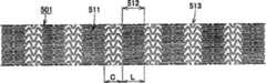
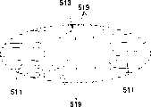
本发明提供有形成大致管状体,且能向大致管状体的半径方向外侧伸长,用于放置在体腔内管状组织中的扩张器501、502、503,具有防止过扩张到大于目标直径的构造的扩张器。The present invention provides
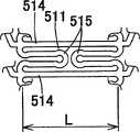
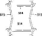
本发明还提供下列构造,即在所述扩张器501、502、503中构成扩张器的基本单元511由未扩张时在扩张器轴向向长度方向配置的主支柱514和在它们之间折叠并在扩张时在周方向支承主支柱514的辅助支柱515所构成,扩张时主支柱514和辅助支柱515形成至少由三边以上构成的环状大致多角形形状,该基本单元511在周方向多个连续,形成带部512,该带部512通过连结单元513在长度方向上成多个连续。The present invention also provides the following structure, that is, the
本发明的扩张器501、502、503在把折叠在主支柱514间的一个基本单元511内辅助支柱515的总长作为A,把基本单元511在周方向多个连续而形成的一个带部512内的基本单元数作为B,把扩张器的目标扩张直径作为D时,最好满足π×D=0.5×A×Sinθ×B且60°≤θ<90°的关系;在把未扩张时基本单元511内主支柱514长度方向的长度作为L时,最好满足L≤A<2×L的关系;在把构成主支柱514、辅助支柱515的线材宽度作为W,厚度作为T时,更最好满足0.5×W≤T≤3×W的关系。The
所述扩张器501、502、503在扩张器扩张时基本单元511的形状是大致三角形或大致四角形或大致梯形,把该基本单元511在周方向多个连续而形成的带部512之间连结的连结单元513具有长度方向可伸缩的结构,同时当把未扩张时连结单元513在扩张器轴向上的长度作为C时最好满足0.3×L≤C≤2L的关系。The
最好这些扩张器501、502、503至少主支柱514和辅助支柱515是由从不锈钢、超弹性金属、弯曲弹性率在1GPa以上的高分子材料、生分解性高分子材料中选择一个以上的材料所构成。Preferably, at least the
本发明提供的扩张器501、502、503,在所述扩张器的外周面上形成筒状的薄膜高分子膜。In the
这些扩张器501、502、503最好具有在X线造影下能确认其位置的不透过X线标志。而且还能给与为预防再狭窄及抑制生成血栓用的药剂和治疗用的遗传基因或进行表面处理。These
进而本发明第三方面在于提供一种闭合型的扩张器,其维持闭合型的优点,反过来解决其缺点,同时不产生敞开型的缺点而只具有它的优点。更具体说就是可以形成在维持闭合型的优点高径向力、卓越架构性的同时进行闭合型的缺点的进入分岔血管的Y移植固定的扩张器。Furthermore, the third aspect of the present invention is to provide a closed-type dilator, which maintains the advantages of the closed type, and in turn solves its disadvantages, and at the same time does not produce the disadvantages of the open type, but only has its advantages. More specifically, it is possible to form a Y-graft-fixed dilator that enters bifurcated blood vessels while maintaining the advantages of the closed type, high radial force, and excellent structural properties.
本发明的闭合型的扩张器603,在由线状单元的支柱604围起来的大致多角形形状图形605具有为了维持卓越架构性能和高径向力所要求程度的直线周长和开口部面积,同时在该多角形形状图形605中通过从该多角形形状图形605的内侧向外侧扩张配置了比较多的可伸展变形的局部折叠部分607,以使该多角形形状图形的开口部扩张(能扩张变形)到为进入侧枝的足够大小。In the closed dilator 603 of the present invention, the substantially polygonal figure 605 surrounded by the
即,本发明扩张器603其形成大致管状体,且能向大致管状体的半径方向外侧伸长,用线状单元的支柱604围起来形成大致多角形形状的图形605在周方向和轴向上多个排列,该多角形形状图形605具有直线周长606、609(原有的直线周长),而且该多角形形状图形605在每一个该多角形形状图形605中具有三个以上可伸展变形的局部折叠部分607、610通过从其内侧向外侧扩张,使扩张后的周长608扩展到该原有的直线周长606、609的1.3倍到2.0倍。每一个该多角形形状图形605中可伸展变形的局部折叠部分607、610的数目最好与该多角形的边数相同。That is, the dilator 603 of the present invention is formed into a substantially tubular body, and can be extended outward in the radial direction of the substantially tubular body, and is surrounded by the
本发明的扩张器603,其形成大致管状体,且能向大致管状体的半径方向外侧伸长,用线状单元的支柱604围起来形成大致多角形形状的图形605在周方向和轴向上多个排列,该多角形形状图形605具有直线周长606、609,而且该多角形形状图形605在该多角形形状图形605中具有可伸展变形的部分607、610,通过从其内侧向外侧扩张,使该多角形形状图形605的周长扩展到该直线周长606、609的1.3倍到2.0倍,该可伸展变形部分的该多角形边方向的直线长度合计形成到该多角形形状图形605的直线长度的1/3到1倍。The dilator 603 of the present invention is formed into a substantially tubular body, and can be extended outward in the radial direction of the substantially tubular body, and is surrounded by a
上述扩张器603通过在周方向和轴向上具有多个多角形图形605,在能维持高径向力的同时具有卓越的架构性。而且如上所述,由于在各个多角形形状图形605中,比较多的存在可伸展变形的局部折叠部分607、610,所以通过该多角形形状图形605利用配置在侧枝的其他的扩张器供给导管支架的扩张能使该角形形状图形605的周长产生大的变形,从而能进入分岔血管并进行Y移植。The above-mentioned dilator 603 has excellent structural properties while maintaining a high radial force by having a plurality of polygonal figures 605 in the circumferential direction and the axial direction. And as mentioned above, since in each polygonal shape figure 605, there are relatively many partially folded
特开平10-137345号、特表平10-503676号等记载的技术中支柱形成的菱形部存在两个相对的U字状部分,其目的是给予扩张器以轴向柔软性,该U字状部分是为了能进行Y移植而不是伸展变形的部分,所以这样的记载全都没有。而且实际上每一个菱形在专利说明书上只有两处所述的U字状部分,通过上述的扩张器供给导管的支架扩张扩展,不能得到为进行侧枝进入的足够的开口面积。In the techniques described in JP-10-137345 and JP-10-503676, etc., there are two opposing U-shaped parts in the rhombus formed by the struts, the purpose of which is to give the dilator axial flexibility. Part of it is for Y transplantation rather than stretch deformation, so there is no such record at all. And in fact, each rhombus has only two U-shaped parts described in the patent specification, and the expansion of the stent supplied by the above-mentioned dilator can not obtain enough opening area for the side branch to enter.
附图说明Description of drawings
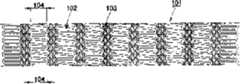
图1是表示本发明第一方面第一实施例扩张器101的展开图;Fig. 1 is a developed view showing a
图2是表示图1所示扩张器101的圆周方向能伸长的大致波形结构单元102的说明图;FIG. 2 is an explanatory diagram showing a roughly
图3是表示图1所示扩张器101的轴向能伸长的大致波形结构单元103的说明图;FIG. 3 is an explanatory diagram showing an axially extendable roughly wave-shaped
图4是图1所示扩张器101未扩张时的展开图;FIG. 4 is an expanded view of the
图5是表示第一实施例变形例扩张器101的展开图;Fig. 5 is a developed view showing a modified example of the
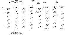
图6是表示本发明第一方面第二实施例扩张器201的展开图;Fig. 6 is a developed view showing the
图7是表示图6所示扩张器201的圆周方向能伸长的大致波形结构单元202的说明图;FIG. 7 is an explanatory diagram showing a roughly wave-shaped
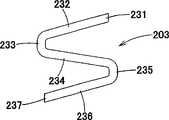
图8是表示图6所示扩张器201的圆周方向能伸长的大致波形结构单元203的说明图;FIG. 8 is an explanatory diagram showing a roughly wave-shaped
图9是表示图6所示扩张器201的轴向能伸长的大致波形结构单元204的说明图;FIG. 9 is an explanatory diagram showing an axially extendable roughly wave-shaped
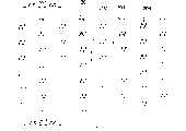
图10是图6所示扩张器201未扩张时的展开图;FIG. 10 is an expanded view of the
图11是图6所示扩张器201扩张后的展开图;FIG. 11 is an expanded view of the expanded
图12是表示第二实施例变形例扩张器201的展开图;Fig. 12 is a developed view showing a
图13是表示本发明第一方面第三实施例扩张器301的展开图;Fig. 13 is a developed view showing the
图14是表示第三实施例变形例扩张器303的展开图;Fig. 14 is a developed view showing a dilator 303 according to a modified example of the third embodiment;
图15是表示第三实施例的其他变形例扩张器305的扩张器扩张后的展开图;Fig. 15 is an expanded view showing the expanded dilator of another modified
图16是图15所示扩张器305扩张前的展开图;Fig. 16 is an expanded view of the
图17是表示本发明第一方面第四实施例扩张器401的展开图;Fig. 17 is a developed view showing the
图18是图17所示扩张器401的扩张器中央部分的展开图;Fig. 18 is an expanded view of the central part of the
图19是图17所示扩张器401的扩张器两端部分的展开图;Fig. 19 is an expanded view of the two ends of the dilator of the
图20是图17所示扩张器401扩张前的展开图;Fig. 20 is an expanded view of the
图21是表示第四实施例变形例402的展开图;Fig. 21 is a developed view showing a modified example 402 of the fourth embodiment;
图22是图21所示扩张器402的扩张器中央部分的展开图;FIG. 22 is an expanded view of the central part of the
图23是图21所示扩张器402的扩张器两端部分的展开图;FIG. 23 is an expanded view of the two ends of the
图24是表示第四实施例其他变形例403的展开图;Fig. 24 is a developed view showing another modified example 403 of the fourth embodiment;
图25是图24所示扩张器403的扩张器中央部分的展开图;Fig. 25 is an expanded view of the central part of the dilator 403 shown in Fig. 24;
图26是图24所示扩张器3的扩张器两端部分的展开图;Fig. 26 is an expanded view of the two ends of the dilator of the dilator 3 shown in Fig. 24;
图27是表示本发明第二方面实施例扩张器501的展开图;Fig. 27 is an expanded view showing the
图28是表示图27所示扩张器501扩张前基本单元的局部放大图;Fig. 28 is a partial enlarged view of the basic unit before the
图29是表示图27所示扩张器501扩张后基本单元的局部放大图;Fig. 29 is a partial enlarged view of the expanded basic unit of the
图30是把图27扩张器501扩张前基本单元的支柱用线段模式化的说明图;Fig. 30 is an explanatory diagram of modeling the struts of the basic unit before the expansion of the
图31是图27所示扩张器501扩张后的展开图;Fig. 31 is an expanded view of the expanded
图32是把图27所示扩张器501的一部分断裂表示的立体放大图;Figure 32 is a perspective enlarged view showing a part of the
图33是表示扩张器扩张时产生塑性变形部分的形状变化例的局部放大图;Fig. 33 is a partial enlarged view showing an example of the shape change of the plastically deformed portion when the dilator expands;
图34是图33所示形状变化部分的剖面放大图;Figure 34 is an enlarged cross-sectional view of the shape change portion shown in Figure 33;
图35是本发明第二方面另一实施例扩张器502扩张前的展开图;Fig. 35 is an expanded view of the
图36是本发明第二方面又一实施例扩张器503扩张前的展开图;Fig. 36 is an expanded view of the
图37是图35所示扩张器502扩张后的展开图;Fig. 37 is an expanded view of the expanded
图38是图36所示扩张器503扩张后的展开图;Fig. 38 is an expanded view of the expanded
图39是表示本发明第二方面扩张器的连结单元513一例的局部放大图;Fig. 39 is a partially enlarged view showing an example of the connecting
图40是用本发明第二方面扩张器的连结单元513表示对长度方向垂直力给予柔软性例的局部放大图;Fig. 40 is a partially enlarged view showing an example of giving flexibility to a vertical force in the longitudinal direction by using the connecting
图41是用本发明第二方面扩张器的连结单元513表示对长度方向垂直力给予柔软性的另一例的局部放大图;Fig. 41 is a partially enlarged view showing another example of imparting flexibility to the vertical force in the longitudinal direction by using the connecting
图42是用本发明第二方面扩张器的连结单元513表示对长度方向垂直力给予柔软性的另一例的局部放大图;Fig. 42 is a partially enlarged view showing another example of imparting flexibility to the vertical force in the longitudinal direction by using the connecting
图43是用本发明第二方面扩张器的连结单元513表示对长度方向垂直力给予柔软性的另一例的局部放大图;Fig. 43 is a partially enlarged view showing another example of imparting flexibility to the vertical force in the longitudinal direction by using the connecting
图44是表示本发明第二方面扩张器501的带部512和连结单元513的局部放大图;Fig. 44 is a partially enlarged view showing the
图45是表示Y扩张器或Y移植的说明图;Fig. 45 is an explanatory diagram showing a Y dilator or a Y graft;
图46是表示本发明第三方面扩张器603实施例的展开图;Fig. 46 is an expanded view showing an embodiment of a dilator 603 according to the third aspect of the present invention;
图47是用图46所示的扩张器603表示原有的直线周长606的多角形形状图形605的局部放大图;Figure 47 is a partial enlarged view of the polygonal shape figure 605 representing the original straight line perimeter 606 with the dilator 603 shown in Figure 46;
图48是表示特定的多角形形状图形605的开口部被扩张后其周长608的展开图;FIG. 48 is an expanded view showing the
图49是表示本发明第三方面另一实施例扩张器603的多角形形状图形605的局部放大图;Fig. 49 is a partially enlarged view showing a polygonal shape figure 605 of a dilator 603 according to another embodiment of the third aspect of the present invention;
图50是在图49所示实施例表示能伸展变形的局部部分的多角形边方向直线长度的多角形形状图形605的局部放大图。FIG. 50 is a partially enlarged view of a polygonal shape figure 605 showing the linear length of the polygon side in the stretchable deformable partial portion in the embodiment shown in FIG. 49 .
具体实施方式Detailed ways
下面参照附图说明本发明扩张器的实施例,但本发明不限定于此。Embodiments of the dilator of the present invention will be described below with reference to the accompanying drawings, but the present invention is not limited thereto.
图1~图5表示了本发明第一方面第一实施例的扩张器,图1是扩张器101的展开图。扩张器101形成大致管状体,且能向管状体的半径方向外侧伸长,由圆周方向能伸长的大致波形结构单元102和轴向能伸长的大致波形结构单元103构成,三个所述圆周方向能伸长的大致波形结构单元102配置在扩张器的大致圆周方向上相互不直接连接,同时六个所述轴向能伸长的大致波形结构单元103配置在扩张器的圆周方向上相互不直接连接,它们相互在扩张器轴向上交替周期性地连续,构成扩张器。圆周每一周上所述圆周方向能伸长的大致波形结构单元102和所述轴向能伸长的大致波形结构单元103的个数由制作的扩张器的长度、外径共同决定,并不限定于三个所述圆周方向能伸长的大致波形结构单元102和六个所述轴向能伸长的大致波形结构单元103。扩张器101通过同时具有扩张器的圆周方向能伸长的单元和轴向能伸长的单元而能向半径方向外侧扩张,这时能减少扩张器的轴向收缩。所述圆周方向或轴向能伸长的大致波形结构单元102、大致波形结构单元103各自配置在扩张器的大致圆周方向上相互不直接连接,这样能给予扩张器以柔软性。1 to 5 show the dilator according to the first embodiment of the first aspect of the present invention, and FIG. 1 is a developed view of the
这里所说的圆周方向或轴向能伸长结构单元是指在管状的扩张器的圆周方向、扩张器的轴向(长度方向)上分别具有能伸长的结构单元的意思,且最好是能收缩的结构。例如扩张器配置在笔直的血管中时基本上是仅伸长变形,没问题,但配置在弯曲的血管中时,弯曲部的外侧除在扩张时产生的伸长以外用于配置血管的形状还产生多余的伸长。这时若在弯曲部的内侧能收缩变形就能减少由弯曲血管外侧多余伸长所引起的扩张器支柱间隔过大。扩张器101所示的圆周方向及轴向能伸长的大致波形结构单元102、大致波形结构单元103分别是也能收缩的结构。The circumferential direction or the axially extensible structural unit mentioned here means that the circumferential direction of the tubular dilator and the axial direction (length direction) of the dilator respectively have the meaning of the structural unit that can be stretched, and preferably can be contracted. Structure. For example, when the dilator is arranged in a straight blood vessel, it is basically only elongated and deformed, and there is no problem. However, when it is arranged in a curved blood vessel, the outer side of the curved part is used to configure the shape of the blood vessel in addition to the elongation that occurs during expansion. produce excess elongation. At this time, if the inner side of the curved portion can be contracted and deformed, the excessive expansion of the struts of the dilator caused by the excessive elongation of the outer side of the curved blood vessel can be reduced. The generally wave-shaped
大致波形结构单元102、大致波形结构单元103只要是分别在圆周方向、轴向能伸长的结构,可以是图1所示以外的各种形状。例如圆周方向能伸长的大致波形结构单元102为了调整被要求的伸长时尺寸、扩张力,有可能调整角度等和变更由曲面形成整体等的形状。但所述圆周方向能伸长的大致波形结构单元102最好是同时具有两个以上峰和谷顶部的结构,若比两个少时则在具有的伸长能力上难于确保连接处的数目。理想的是最好具有四个结构。图1所示扩张器101的圆周方向能伸长的大致波形结构单元102在端部具有峰和谷的顶部,包括其端部峰和谷顶部合起来的数目是四个。为了调整被要求的伸长时尺寸、扩张力,轴向能伸长的大致波形结构单元103例如对弯曲处的数目、角度等可以是各种形状。但最好是轴向能伸长的大致波形结构单元103的峰和谷顶部合起来的数目具有一个以上的结构,若一个也没有话则难于具有伸长能力。理想的是两个或四个,更理想的是最好具有四个结构。图1所示扩张器101的轴向能伸长的大致波形结构单元103其峰和谷合起来的数目是四个。The roughly wave-shaped
在扩张器的大致圆周方向配置不直接连续的多个所述圆周方向能伸长的大致波形结构单元102而构成的圆周单元104,其轴向长度短,在向弯曲的血管插入时,由于扩张器顺利地弯曲,所以不会损伤血管壁是合适的。理想的是最好扩张器每10mm具有五个以上圆周单元104。In the substantially circumferential direction of the dilator, the
若在圆周每一周的所述圆周方向能伸长的大致波形结构单元102和轴向能伸长的大致波形结构单元103的个数若少的话,则不能得到大的血管保持力。理想的是圆周每一周在所述圆周方向能伸长的大致波形结构单元102有三个以上,所述轴向能伸长的大致波形结构单元103有六个以上,这时就能表现高的血管保持力。If the number of the substantially wave-shaped
扩张器101的两端的所述圆周方向能伸长的大致波形结构单元102直接连续连接,在圆周方向上能伸长的大致波形形状构成环绕一周。这样,扩张器两端与扩张器中央部分相比对血管收缩力的抵抗变大,而且扩张时也不产生扩张器径的两端部比中央部翘曲变大的问题。The two ends of the
在构成扩张器轴向两端的圆周方向能伸长的大致波形结构单元102的扩张器轴向长度与构成扩张器轴向两端以外的圆周方向能伸长的大致波形结构单元102的扩张器轴向长度相比,可以缩短。这时,与不缩短的情况相比其对血管收缩力的抵抗更大,而且扩张时也不产生扩张器径的两端部比中央部翘曲变大的问题。The dilator axial length of the roughly wave-shaped
只对扩张器的轴向两端与扩张器轴向两端以外处进行比较,可以把圆周方向能伸长的大致波形结构单元102的支柱宽度加宽。这时与不加宽的情况相比其对血管收缩力的抵抗更大,而且扩张时也不产生扩张器径的两端部比中央部翘曲变大的问题。但这里所说的支柱指的是构成扩张器的线状构件。By comparing only the axial ends of the dilator with those other than the axial ends of the dilator, it is possible to widen the strut width of the generally wave-shaped
只对扩张器的轴向两端与扩张器轴向两端以外处进行比较,可以把圆周方向能伸长的大致波形结构单元102的支柱厚度增厚。这时与不增厚的情况相比其对血管收缩力的抵抗更大,而且扩张时也不产生扩张器径的两端部比中央部翘曲变大的问题。Comparing only the axial ends of the dilator with those other than the axial ends of the dilator, it is possible to increase the thickness of the struts of the generally wave-shaped
只对扩张器的轴向两端与扩张器轴向两端以外处进行比较,可以并用圆周方向能伸长的大致波形结构单元102的扩张器轴向长度短的、支柱宽度宽的、支柱厚度厚的。而且随着从扩张器的轴向中央部分向端部变化可以把从所述圆周方向能伸长的大致波形结构单元102和所述轴向能伸长的大致波形结构单元103中选择的一个以上的扩张器轴向长度有等级地缩短。这时,与不进行有等级地缩短的情况相比其对血管收缩力的抵抗更加变大,而且扩张时也不产生扩张器径的两端部比中央部翘曲变大的问题,且扩张器的轴向柔软性没有大的变化,能使柔软性有等级地变化。Comparing only the axial ends of the dilator with those other than the axial ends of the dilator, the dilator with the roughly wave-shaped
随着从扩张器的轴向中央部分向端部变化,可以把从所述圆周方向能伸长的大致波形结构单元102和所述轴向能伸长的大致波形结构单元103中选择的一个以上的支柱宽度有等级地加宽。这时,与不进行有等级地加宽的情况相比其对血管收缩力的抵抗更加变大,而且扩张时也不产生扩张器径的两端部比中央部翘曲变大的问题,且扩张器的轴向柔软性没有大的变化,能使柔软性有等级地变化。As the dilator changes from the axial central part to the end, more than one strut selected from the circumferentially extensible generally wave-shaped
随着从扩张器的轴向中央部分向端部变化,可以把从所述圆周方向能伸长的大致波形结构单元102和所述轴向能伸长的大致波形结构单元103中选择的一个以上的支柱厚度有等级地增厚。这时,与不进行有等级地制大的情况相比其对血管收缩力的抵抗更加变大,而且扩张时也不产生扩张器径的两端部比中央部翘曲变大的问题,且扩张器的轴向柔软性没有大的变化,能使柔软性有等级地变化。As the dilator changes from the axial central part to the end, more than one strut selected from the circumferentially extensible generally wave-shaped
随着从扩张器的轴向中央部分向端部变化,可以从所述圆周方向能伸长的大致波形结构单元102和所述轴向能伸长的大致波形结构单元103中选择一个以上的扩张器把轴向长度有等级地缩短、把支柱宽度有等级地加宽、把支柱厚度有等级地增厚等同时进行。As the dilator changes from the axial central part to the end, more than one dilator handle can be selected from the circumferentially elongatable substantially wave-shaped
图1的扩张器101在扩张器轴向上由9列包括两端的所述圆周方向能伸长的大致波形结构单元102和8列所述轴向能伸长的大致波形结构单元103交替连续构成。该9列包括两端的所述圆周方向能伸长的大致波形结构单元102和8列所述轴向能伸长的大致波形结构单元103由制作的扩张器的长度、外径共同决定,并不限定包括两端的所述圆周方向能伸长的大致波形结构单元102是9列,所述轴向能伸长的大致波形结构单元103是8列。The
如图1所示,所述圆周方向能伸长的大致波形结构单元102并列在扩张器的圆周方向上并不直接连续。所述轴向能伸长的大致波形结构单元103也并列在扩张器的圆周方向上并不直接连续。As shown in FIG. 1 , the generally wave-shaped
图2表示了圆周方向能伸长的大致波形结构单元102的一种形态,图3表示了轴向能伸长的大致波形结构单元103的一种形态。所述圆周方向能伸长的大致波形结构单元102由直线部122、124、126和连结部121、123、125、127所构成,所述轴向能伸长的大致波形结构单元103由直线部133、135、137和连结部131、139及弯曲部132、134、136、138所构成。所有的连结部121、123、125、127因为分别与连结部131或139的任一个连接,所以扩张器扩张时在所述圆周方向能伸长的大致波形结构单元102和轴向能伸长的大致波形结构单元103上力容易均匀地传递,能使扩张器支柱均衡扩张。FIG. 2 shows a form of a substantially wave-shaped
对所述圆周方向能伸长的大致波形结构单元102的直线部122、124、126和所述轴向能伸长的大致波形结构单元103的直线部133、135、137来说,当增大支柱的宽度及厚度时则损害扩张器轴向的柔软性,反过来当减少宽度及厚度时则对从外周受到的径向应力的承受力变小。因此,为了恰当地满足扩张器的轴向柔软性及对从外周受到的径向应力的承受力这两者的性能,所述圆周方向能伸长的大致波形结构单元102的直线部122、124、126最好是宽度从80μm到150μm且厚度从70μm到150μm,更理想的是最好宽度从120μm到140μm且厚度从100μm到120μm。所述轴向能伸长的大致波形结构单元103的直线部133、135、137最好是宽度从50μm到100μm且厚度从50μm到150μm,更理想的是最好宽度从60μm到80μm且厚度从80μm到120μm。但圆周方向能伸长的大致波形结构单元102、103都能随构成扩张器的材料和使用部位的不同而调整到上述尺寸以外的各种尺寸。For the linear portions 122, 124, 126 of the substantially wave-shaped
若所述圆周方向能伸长的大致波形结构单元102的轴向长度长,则在把扩张器向弯曲的血管插入时扩张器不能顺利弯曲,支柱的角容易立起,反过来若所述圆周方向能伸长的大致波形结构单元102的轴向长度短,则不能把扩张器直径扩张到扩张时所需要扩张器直径。若所述轴向能伸长的大致波形结构单元103的轴向长度长,则扩张时由扩张器支柱间形成的空隙变大,管状组织的内皮细胞从该空隙部分突出很多,也有时成为再狭窄的原因。反过来若所述轴向能伸长的大致波形结构单元103的轴向长度短,则损害扩张器轴向的柔软性。因此所述圆周方向能伸长的大致波形结构单元102的轴向长度最好是从0.8mm到1.8mm,更理想的是从1.0mm到1.4mm。所述轴向能伸长的大致波形结构单元103的轴向长度最好是从0.5mm到1.5mm,更理想的是从0.7mm到1.0mm。但大致波形结构单元102、103都能随构成扩张器的材料和使用部位的不同而调整到上述尺寸以外的各种尺寸。If the axial length of the generally wave-shaped
本发明的扩张器可用具有合适刚性和弹性的不锈钢、Ni-Ti合金、Cu-Al-Mn合金等金属和具有合适刚性和弹性的高分子材料制作。The dilator of the present invention can be made of metals such as stainless steel, Ni-Ti alloy, Cu-Al-Mn alloy with proper rigidity and elasticity, and polymer materials with suitable rigidity and elasticity.
本发明的扩张器也可用喷镀保护材料、含浸及包覆医药材料中的任一种进行表面加工。The dilator of the present invention can also be surface processed by spraying protective materials, impregnating and coating medical materials.
作为扩张器成型方法可以是激光加工法、放电加工法、机械的切削方法、蚀刻方法等。The dilator forming method may be a laser processing method, an electrical discharge machining method, a mechanical cutting method, an etching method, or the like.
图4表示了安装在支架导管内时的本发明扩张器的展开图。如图4所示,即使被安装在支架导管内时,所述圆周方向能伸长的大致波形结构单元102也排列在扩张器的圆周方向上,且所述轴向能伸长的大致波形结构单元103也排列在扩张器的圆周方向上,所述圆周方向能伸长的大致波形结构单元102排列在圆周方向上构成的圆周单元104和所述轴向能伸长的大致波形结构单元103排列在圆周方向上构成的圆周单元在扩张器的轴向上交替连续。这样,扩张器扩张时即使圆周方向能伸长的大致波形结构单元102在轴向收缩,也由于轴向能伸长的大致波形结构单元103在轴向扩张,所以扩张器的全长能在扩张器扩张前后大体保持相同的长度。Figure 4 shows an expanded view of the dilator of the present invention when installed in a stent catheter. As shown in FIG. 4 , even when installed in a stent catheter, the roughly wave-shaped
图5表示了本发明第一方面第一实施例的变形例。即在本实施例中仅扩张器的轴向两端由直接连续的多个圆周方向能伸长的大致波形结构单元102在扩张器的圆周方向上配列形成,且轴向长度与构成扩张器轴向两端以外的圆周方向能伸长的大致波形结构单元102的轴向长度相比短。这样,能减少扩张器端部支柱的翘曲,同时能增大两端部对血管收缩力的抵抗力。通过仅增加两端部的支柱宽度和厚度,能增大对血管收缩力的抵抗力。Fig. 5 shows a modified example of the first embodiment of the first aspect of the present invention. That is, in this embodiment, only the axial ends of the dilator are formed by arranging a plurality of directly continuous roughly wave-shaped
图6~图12表示了本发明第一方面第二实施例的扩张器,图6是本发明扩张器201的展开图。扩张器201是形成大致管状体,且能向管状体的半径方向外侧伸长的扩张器,由圆周方向能伸长的大致波形结构单元202和圆周方向能伸长的大致波形结构单元203和轴向能伸长的大致波形结构单元204构成,三个所述圆周方向能伸长的大致波形结构单元202相互不直接连接地配置在扩张器的大致圆周方向上,同时三个所述圆周方向能伸长的大致波形结构单元203相互不直接连接地配置在扩张器的大致圆周方向上,而且六个所述轴向能伸长的大致波形结构单元204相互不直接连接地配置在扩张器的圆周方向上,它们相互在扩张器轴向上交替周期性地连续构成扩张器。圆周每一周上所述圆周方向能伸长的大致波形结构单元202、所述圆周方向能伸长的大致波形结构单元203和所述轴向能伸长的大致波形结构单元204的个数由制作的扩张器的长度、外径共同决定,并不限定所述大致波形结构单元202为三个所述大致波形结构单元203为三个和所述大致波形结构单元204为六个。扩张器201通过同时具有扩张器的圆周方向能伸长的单元和轴向能伸长的单元而能向半径方向外侧扩张,这时能减少扩张器的轴向收缩。所述圆周方向或轴向能伸长的大致波形结构单元202、203、204相互不直接连接各自配置在扩张器的大致圆周方向上,这样能给予扩张器以柔软性。6 to 12 show the dilator according to the second embodiment of the first aspect of the present invention, and FIG. 6 is an expanded view of the
这里所说的圆周方向或轴向能伸长结构单元是指在管状的扩张器的圆周方向、扩张器的轴向(长度方向)上分别具有能伸长的结构单元,且最好是能收缩的结构。例如扩张器配置在笔直的血管中时基本上是仅伸长变形没问题,但被配置在弯曲的血管中时,弯曲部的外侧除用于配置扩张时产生的伸长以外血管的形状还产生多余的伸长。这时,若弯曲部的内侧能收缩变形就能减少由弯曲血管外侧多余伸长而引起的扩张器支柱间隔过大。扩张器201所示的圆周方向及轴向能伸长的大致波形结构单元202、203、204也分别是能收缩的结构。The circumferential direction or axially stretchable structural unit mentioned here refers to the circumferential direction of the tubular dilator and the axial direction (length direction) of the dilator respectively have a structural unit that can be stretched, and is preferably a structure that can be contracted. . For example, when the dilator is arranged in a straight blood vessel, it is basically only elongated and deformed, but when it is arranged in a curved blood vessel, the outer side of the curved part is used to form the shape of the blood vessel in addition to the elongation that occurs during the expansion. excess elongation. At this time, if the inner side of the curved part can be contracted and deformed, the excessive expansion of the struts of the dilator caused by the excessive extension of the outer side of the curved blood vessel can be reduced. The generally wave-shaped
大致波形结构单元202、203和204若是分别在圆周方向和轴向能伸长的结构,可形成图6所示以外的各种形状。例如圆周方向能伸长的大致波形结构单元202、203,为了调整所要求的伸长时尺寸、扩张力,可以调整角度等和变更用曲面形成整体等的形状。但所述圆周方向能伸长的大致波形结构单元202、203都最好是同时具有两个以上峰和谷顶部的结构,若比两个少时则在具有的伸长能力后难于确保连接处的数目。理想的是最好具有四个结构。图6所示扩张器201的圆周方向能伸长的大致波形结构单元202、203的端部都具有峰和谷的顶部,包括其端部的峰和谷顶部合起来的数目是四个。另外,为了调整所要求的伸长时尺寸、扩张力,轴向能伸长的大致波形结构单元204,相对例如弯曲处的数目、角度等可以是各种形状。但最好是轴向能伸长的大致波形结构单元204的峰和谷顶部合起来的数目具有一个以上的结构,若一个也没有则难于具有伸长能力。理想的是两个或四个、更理想的是最好具有四个结构。图6所示扩张器201的轴向能伸长的大致波形结构单元204的峰和谷合起来的数目是四个。If the roughly wave-shaped
图6所示的扩张器201的圆周方向能伸长的大致波形结构单元202和大致波形结构单元203具有相互线对称形状的关系。线对称形状在扩张时容易把支柱均匀扩张。In the
在扩张器的大致圆周方向配置不直接连续的多个所述圆周方向能伸长的大致波形结构单元202而构成的圆周单元205,并在扩张器的大致圆周方向配置不直接连续的多个所述圆周方向能伸长的大致波形结构单元202而构成的圆周单元206,最好其轴向长度短;在向弯曲的血管插入时,由于扩张器顺利地弯曲,所以不会损伤血管壁是合适的。最好扩张器长度每10mm共具有五个以上的圆周单元205和圆周单元206。The
若圆周每一周的所述圆周方向能伸长的大致波形结构单元202、203和大致波形结构单元204的个数少,则不能实现大的血管保持力。理想的是圆周每一周圆周方向能伸长的大致波形结构单元202或圆周方向能伸长的大致波形结构单元203有三个以上,所述轴向能伸长的大致波形结构单元204有六个以上,这时,就能出现高的血管保持力。If the number of the generally wave-shaped
扩张器201的两端由所述圆周方向能伸长的大致波形结构单元202或圆周方向能伸长的大致波形结构单元203直接连续连接,在圆周方向上构成能伸长的大致波形形状环绕一周。这样,扩张器两端与扩张器中央部分相比对血管收缩力的抵抗变大,而且扩张时也不产生扩张器径的两端部比中央部翘曲变大的问题。The two ends of the
构成扩张器轴向两端的圆周方向能伸长的大致波形结构单元202或203的扩张器轴向长度与构成扩张器轴向两端以外的圆周方向能伸长的大致波形结构单元202或203的扩张器轴向长度相比可以缩短。这时,与不缩短的情况相比,其对血管收缩力的抵抗更大,而且扩张时也不产生扩张器径的两端部比中央部翘曲变大的问题。The axial length of the dilator constituting the roughly wave-shaped
只对扩张器的轴向两端与扩张器轴向两端以外处进行比较,可以把圆周方向能伸长的大致波形结构单元202或203、或它们两者的支柱宽度加宽。这时与不加宽的情况相比,其对血管收缩力的抵抗更大,而且扩张时也不产生扩张器径的两端部比中央部翘曲变大的问题。这里所说的支柱是指构成扩张器的线状构件。Comparing only the axial ends of the dilator with the parts other than the axial ends of the dilator, it is possible to widen the strut width of the generally wave-shaped
只对扩张器的轴向两端与扩张器轴向两端以外处进行比较,可以把圆周方向能伸长的大致波形结构单元202或203、或它们两者的支柱厚度增厚。这时与不增厚的情况相比,其对血管收缩力的抵抗更大,而且扩张时也不产生扩张器径的两端部比中央部翘曲变大的问题。Comparing only the axial ends of the dilator with those other than the axial ends of the dilator, it is possible to increase the thickness of the struts of the generally wave-shaped
只对扩张器的轴向两端与扩张器轴向两端以外处进行比较,可以并用圆周方向能伸长的大致波形结构单元202或203、或它们两者的扩张器轴向长度短的、支柱宽度宽的、支柱厚度厚的。Only the axial ends of the dilator are compared with those other than the axial ends of the dilator, and the generally wave-shaped
而且随着从扩张器的轴向中央部分向端部变化可以把从圆周方向能伸长的大致波形结构单元202和203和轴向能伸长的大致波形结构单元204中选择的一个以上的扩张器轴向长度有等级地缩短。这时,与不进行有等级地缩短的情况相比,其对血管收缩力的抵抗更大,而且扩张时也不产生扩张器径的两端部比中央部翘曲变大的问题,且扩张器的轴向柔软性没有大的变化,能使柔软性有等级地变化。And along with the change from the axial central part of the dilator to the end, more than one expander shaft can be selected from the roughly wave-shaped
随着从扩张器的轴向中央部分向端部变化,可以把从圆周方向能伸长的大致波形结构单元202和203和轴向能伸长的大致波形结构单元204中选择的一个以上的支柱宽度有等级地加宽。这时,与不进行有等级地加宽的情况相比,其对血管收缩力的抵抗大,而且扩张时也不产生扩张器径的两端部比中央部翘曲变大的问题,且扩张器的轴向柔软性没有大的变化,能使柔软性有等级地变化。As the dilator is changed from the axial central portion to the end, more than one strut width selected from the circumferentially extensible approximately wave-shaped
随着从扩张器的轴向中央部分向端部变化,可以把从圆周方向能伸长的大致波形结构单元202和203和轴向能伸长的大致波形结构单元204中选择的一个以上的支柱厚度有等级地增厚。这时,与不进行有等级地增厚的情况相比,其对血管收缩力的抵抗更大,而且扩张时也不产生扩张器径的两端部比中央部翘曲变大的问题,且扩张器的轴向柔软性没有大的变化,能使柔软性有等级地变化。As the dilator changes from the axial central portion to the end, the thickness of one or more struts selected from the circumferentially extensible generally wave-shaped
随着从扩张器的轴向中央部分向端部变化,可以从所述圆周方向能伸长的大致波形结构单元202和203和轴向能伸长的大致波形结构单元204中选择一个以上的把扩张器轴向长度有等级地缩短、把支柱宽度有等级地加宽、把支柱厚度有等级地增厚等同时进行。As the dilator changes from the axial central part to the end, more than one dilator can be selected from the circumferentially elongatable substantially wave-shaped
如图6所示,所述圆周方向能伸长的大致波形结构单元202及203并列在扩张器的圆周方向上并不直接连续。所述轴向能伸长的大致波形结构单元204也并列在扩张器的圆周方向上并不直接连续。As shown in FIG. 6 , the generally wave-shaped
图7表示了圆周方向能伸长的大致波形结构单元202的一种形态,图8表示了圆周方向能伸长的大致波形结构单元203的一种形态,图9表示了轴向能伸长的大致波形结构单元204的一种形态。所述圆周方向能伸长的大致波形结构单元202由直线部222、224、226和连结部221、223、225、227所构成,所述大致波形结构单元203由直线部232、234、236和连结部231、233、235、237所构成,所述大致波形结构单元204由直线部243、245、247和连结部241、249及弯曲部242、244、246、248所构成。所述圆周方向能伸长的大致波形结构单元202及203所有的连结部221、223、225、227、231、233、235、237因为分别与所述轴向能伸长的大致波形结构单元204的连结部241或249的任一个连接,所以扩张器扩张时在所述大致波形结构单元202、203和所述大致波形结构单元204上力容易均匀地传递,能使扩张器支柱均衡扩张。Fig. 7 has shown a kind of form of the roughly
对所述圆周方向能伸长的大致波形结构单元202的直线部222、224、226和所述圆周方向能伸长的大致波形结构单元203的直线部232、234、236和所述轴向能伸长的大致波形结构单元204的直线部243、245、247来说,当增大支柱的宽度及厚度时则损害扩张器轴向的柔软性,反过来当减少宽度及厚度时则对从外周受到的径向应力的承受力变小。因此,为了恰当地满足扩张器的轴向柔软性及对从外周受到的径向应力的承受力这两者的性能,所述圆周方向能伸长的大致波形结构单元202及203的直线部222、224、226、232、234、236最好是宽度从80μm到150μm且厚度从70μm到150μm,更理想的是最好宽度从120μm到140μm且厚度从100μm到120μm。所述轴向能伸长的大致波形结构单元204的直线部243、245、247最好是宽度从50μm到100μm且厚度从50μm到150μm,更理想的是最好宽度从60μm到80μm且厚度从80μm到120μm。圆周方向能伸长的大致波形结构单元202、203、轴向能伸长的大致波形结构单元204都能随构成扩张器的材料和使用部位的不同而调整到上述尺寸以外的各种尺寸。For the linear parts 222, 224, 226 of the roughly wave-shaped
若所述圆周方向能伸长的大致波形结构单元202及203的轴向长度长,则在把扩张器向弯曲的血管插入时扩张器不能顺利弯曲,支柱的角容易立起,反过来若所述圆周方向能伸长的大致波形结构单元202及203的轴向长度短,则不能把扩张器直径扩张到扩张时所需要扩张器直径。若所述轴向能伸长的大致波形结构单元204的轴向长度长,则扩张时由扩张器支柱间形成的空隙变大,管状组织的内皮细胞从该空隙部分突出很多,也有时成为再狭窄的原因。反过来若所述大致波形结构单元204的轴向长度短,则损害扩张器轴向的柔软性。因此所述圆周方向能伸长的大致波形结构单元202及203的轴向长度最好是从0.8mm到1.8mm,更理想的是从1.0mm到1.4mm。所述轴向能伸长的大致波形结构单元204的轴向长度最好是从0.5mm到1.5mm,更理想的是从0.7mm到1.0mm。但圆周方向或轴向能伸长的大致波形结构单元202、203、204都能随构成扩张器的材料和使用部位的不同而调整到上述尺寸以外的各种尺寸。If the axial length of the generally wave-shaped
本发明的扩张器可用具有合适刚性和弹性的不锈钢、Ni-Ti合金、Cu-Al-Mn合金等金属和具有合适刚性和弹性的高分子材料制作。The dilator of the present invention can be made of metals such as stainless steel, Ni-Ti alloy, Cu-Al-Mn alloy with proper rigidity and elasticity, and polymer materials with suitable rigidity and elasticity.
扩张器201也可用喷镀保护材料、含浸及包覆医药品材料这其中的任一种进行表面加工。The
作为扩张器成型方法可以是激光加工法、放电加工法、机械的切削方法、蚀刻方法等。The dilator forming method may be a laser processing method, an electrical discharge machining method, a mechanical cutting method, an etching method, or the like.
图10表示了安装在支架导管内时的本发明扩张器的展开图。如图10所示,即使被安装在支架导管内时,所述圆周方向能伸长的大致波形结构单元202也相互不直接连接排列在扩张器的圆周方向上,构成圆周单元205,且所述圆周方向能伸长的大致波形结构单元203也相互不直接连接排列在扩张器的圆周方向上,构成圆周单元206,且所述轴向能伸长的大致波形结构单元204也相互不直接连接排列在扩张器的圆周方向上构成圆周单元207,所述圆周单元205、所述圆周单元206、所述圆周单元207按在圆周单元205、圆周单元207、圆周单元206、圆周单元207的顺序在扩张器的轴向上周期性地连续。这样,扩张器扩张时即使圆周方向能伸长的大致波形结构单元202或203在轴向上收缩,也由于大致波形结构单元204在轴向上扩张,所以扩张器的全长能在扩张器扩张前后大体保持相同的长度。Figure 10 shows an expanded view of the dilator of the present invention when installed in a stent catheter. As shown in FIG. 10 , even when installed in a stent catheter, the generally wave-shaped
图11表示了扩张后的扩张器的展开图。如图11所示,扩张后的扩张器201除扩张器两端部分以外其组合构成长方的四边形,且所述长方的四边形存在有与扩张器轴向有一定角度的两个方向的四边形,具有如图11所示的规则性并连续。这里所说的四边形与扩张器轴向有一定角度是指四边形没有与扩张器轴向平行的边。这样,在扩张器扩张后,通过与扩张器轴向有一定角度而存在的两种长方的四边形具有如图11所示规则性地被配置,能实现对血管收缩力的抵抗大且轴向柔软的扩张器。Figure 11 shows an expanded view of the expanded dilator. As shown in Figure 11, the expanded
图12表示了本发明第一方面第二实施例的变形例。即本实施例中仅扩张器的轴向两端由直接连续的多个圆周方向能伸长的大致波形结构单元202或大致波形结构单元203在扩张器的圆周方向上配列形成,且仅所述扩张器轴向两端的轴向长度与构成扩张器轴向两端以外的圆周方向能伸长的大致波形结构单元202或203的轴向长度相比短。这样,能减少扩张器端部支柱的翘曲,同时能增大两端部对血管收缩力的抵抗力。通过仅增加两端部的支柱宽度、厚度,能增大对血管收缩力的抵抗力。Fig. 12 shows a modified example of the second embodiment of the first aspect of the present invention. That is to say, in this embodiment, only the axial ends of the dilator are formed by arranging directly continuous multiple roughly wave-shaped
图13~图16表示了本发明第一方面第三实施例的扩张器,图13是本发明扩张器301的展开图。扩张器301是形成大致管状体,且能从大致管状体的内部向半径方向外侧伸长的扩张器,构成所述扩张器的基本单元是大致平行四边形,所述大致平行四边形单元302交替组合构成扩张器301。这里所说的大致平行四边形单元302交替组合是指用展开图看时存在以相互不同方向并列的大致平行四边形单元302,并由它们相互组合而构成。为了把扩张器两端部调整到与扩张器轴向大致垂直的半径断面上,有时仅在扩张器两端部包括大致平行四边形单元以外的单元。13 to 16 show the dilator according to the third embodiment of the first aspect of the present invention, and FIG. 13 is an expanded view of the
通过由大致平行四边形单元302构成,与现在的扩张器相比能减少连接部位,能在扩张器扩张前得到高的柔软性,同时扩张器扩张后通过大致平行四边形单元302交替组合而具有高的径向力。即所述大致平行四边形单元302在扩张器扩张前后与扩张器轴向所成的角度变化,扩张前大致平行四边形单元302与扩张器轴向形成的角度小于扩张后大致平行四边形单元302与扩张器轴向形成的角度。因此,与现在的扩张器相比能减少连接部位,同时能具有在扩张器扩张前具有高的扩张器轴向柔软性在扩张器扩张后径向力高这两种性能。这里径向力是表示对血管收缩力的抵抗。若径向力低则对血管收缩力的抵抗低,相对血管收缩力,扩张器发生缩径而阻碍血流,最坏时有时招致再狭窄,所以高的径向力是必要的。By being composed of approximately
因为扩张器301把大致平行四边形单元302均匀配置,所以能把扩张器的支柱均匀扩张。Since the
只要减少在扩张器301的轴向上排列的大致平行四边形单元302的个数就能得到高的扩张器轴向柔软性,但径向力变低。只要增加所述大致平行四边形单元302的个数就能得到高的径向力,但扩张器轴向柔软性变低。为了得到合适的扩张器轴向柔软性和高的径向力,在扩张器301的轴向上排列的大致平行四边形单元302的个数是扩张器轴向长度每20mm是7个以上11个以下,更理想的是8个以上10个以下。High axial flexibility of the dilator can be obtained by reducing the number of substantially
图14是本发明第一方面第二实施例变形例扩张器303的展开图。扩张器303是形成大致管状体,且能从大致管状体的内部向半径方向外侧伸长的扩张器,构成所述扩张器303的基本单元是大致平行四边形,所述大致平行四边形单元304交替组合构成扩张器303,大致平行四边形单元304由大致直线支柱321和大致波形支柱322构成。这里所说的大致平行四边形单元304交替组合是指用展开图看时存在以相互不同方向并列的大致平行四边形单元304,并由它们相互组合构成。为了把扩张器两端部调整到与扩张器轴向大致垂直的半径断面上,有时仅在扩张器两端部包括大致平行四边形单元以外的单元。Fig. 14 is a developed view of a dilator 303 according to a modified example of the second embodiment of the first aspect of the present invention. The dilator 303 is a dilator that forms a substantially tubular body and can be extended from the inside of the substantially tubular body to the outside in the radial direction. The basic unit constituting the dilator 303 is substantially parallelogram, and the substantially parallelogram units 304 are alternately combined. Constituting the dilator 303 , the substantially parallelogram unit 304 is composed of substantially straight struts 321 and substantially wave-like struts 322 . The alternate combination of approximately parallelogram units 304 here refers to the existence of approximately parallelogram units 304 juxtaposed in different directions when viewed in a developed view, and they are formed by combining them with each other. In order to adjust both ends of the dilator to radial cross-sections substantially perpendicular to the axial direction of the dilator, units other than substantially parallelogram units may be included only at both ends of the dilator.
通过由大致平行四边形单元304构成,与现在的扩张器相比能减少连接部位,能在扩张器扩张前得到高的柔软性,同时扩张器扩张后通过大致平行四边形单元304交替组合而具有高的径向力。即所述大致平行四边形单元304在扩张器扩张前后与扩张器轴向所成的角度有变化,扩张前大致平行四边形单元304与扩张器轴向形成的角度小于扩张后大致平行四边形单元304与扩张器轴向形成的角度。因此与现在的扩张器相比能减少连接部位,同时能具有在扩张器扩张前具有高的扩张器轴向柔软性,在扩张器扩张后径向力高这两种性能。By being composed of approximately parallelogram unit 304, compared with the conventional dilator, the number of connecting parts can be reduced, and high flexibility can be obtained before the dilator is expanded. radial force. That is to say, the angle between the approximately parallelogram unit 304 and the axial direction of the expander changes before and after the expansion of the expander, and the angle formed between the approximately parallelogram unit 304 and the axial direction of the expander before expansion is smaller than that formed by the approximately parallelogram unit 304 after expansion. The angle formed by the axis of the device. Therefore, compared with the current dilator, the number of connecting parts can be reduced, and at the same time, it can have high axial flexibility of the dilator before the dilator is expanded, and high radial force after the dilator is expanded.
因为大致平行四边形单元304具有大致波形支柱322,所以扩张器扩张前能得到更高的扩张器轴向柔软性,同时通过大致波形支柱322的轴向伸缩能防止扩张时扩张器轴向长度的收缩。Because the roughly parallelogram unit 304 has a roughly wave-shaped strut 322, higher axial flexibility of the dilator can be obtained before the dilator is expanded, and at the same time, the axial expansion and contraction of the roughly wave-shaped strut 322 can prevent the shrinkage of the axial length of the dilator during expansion. .
扩张器303把大致平行四边形单元304均匀配置,所以能使扩张器的支柱均匀扩张。The dilator 303 arranges the approximately parallelogram-shaped units 304 uniformly, so that the struts of the dilator can be uniformly expanded.
只要减少在扩张器303的轴向上排列的大致平行四边形的个数就能得到高的扩张器轴向柔软性,但径向力变低。只要增加所述大致平行四边形单元304的个数就能得到高的径向力,但扩张器轴向柔软性变低。为了得到合适的扩张器轴向柔软性和高的径向力,在扩张器303的轴向上排列的大致平行四边形单元304的个数是扩张器轴向长度每20mm是5个以上9个以下,更理想的是6个以上8个以下。High axial flexibility of the dilator can be obtained by reducing the number of substantially parallelograms arranged in the axial direction of the dilator 303, but the radial force becomes lower. As long as the number of the substantially parallelogram units 304 is increased, a high radial force can be obtained, but the axial flexibility of the dilator becomes low. In order to obtain suitable axial flexibility and high radial force of the dilator, the number of roughly parallelogram units 304 arranged in the axial direction of the dilator 303 is 5 or more and 9 or less per 20 mm of the axial length of the dilator. , more ideally more than 6 and less than 8.
图15是本发明第一方面第三实施例其他变形例扩张器305的扩张器扩张后的展开图,图16是所述扩张器305扩张前的展开图。扩张器305是形成大致管状体,且能从大致管状体的内部向半径方向外侧伸长的扩张器,构成所述扩张器305的基本单元是大致平行四边形,所述大致平行四边形单元306交替组合构成扩张器305,大致平行四边形单元306由大致直线支柱331和大致波形支柱332构成。这里所说的大致平行四边形单元306交替组合是指用平面图看时存在以相互不同方向并列的大致平行四边形单元306,并由它们相互组合构成。为了把扩张器两端部调整到与扩张器轴向大致正交的半径断面上,有时仅在扩张器两端部包括大致平行四边形单元以外的单元。扩张器305是在扩张器扩张前大致平行四边形单元306的各边与扩张器轴线方向大致平行(图16),在扩张器扩张后大致平行四边形单元306的各边对扩张器轴线方向具有角度(图15)。FIG. 15 is an expanded view of the
通过由大致平行四边形单元306构成,与现在的扩张器相比能减少连接部位,能在扩张器扩张前得到高的柔软性,同时扩张器扩张后通过大致平行四边形单元交替组合而具有高的径向力。即所述大致平行四边形单元306在扩张器扩张前后与扩张器轴向所成的角度有变化,通过在扩张器扩张前大致平行四边形单元306的各边与扩张器轴线方向大致平行(图16),在扩张器扩张后大致平行四边形单元306的各边对扩张器轴线方向具有角度,这样,与现在的扩张器相比,能同时具有在扩张器扩张前具有高的扩张器轴向柔软性,在扩张器扩张后径向力高这两种性能。By being composed of approximately
因为大致平行四边形单元306具有大致波形支柱332,所以扩张器扩张前能得到更高的扩张器轴向柔软性,同时通过大致波形支柱332的轴向伸缩能防止扩张时扩张器轴向长度的收缩。Because the substantially
扩张器305把大致平行四边形单元306均匀配置,所以能使扩张器的支柱均匀扩张。In the
只要减少在扩张器305的轴向上排列的大致平行四边形单元306的个数就能得到高的扩张器轴向柔软性,但径向力变低。只要增加所述大致平行四边形单元306的个数就能得到高的径向力,但扩张器轴向柔软性变低。为了得到合适的扩张器轴向柔软性和高的径向力,在扩张器305的轴向上排列的大致平行四边形单元306的个数是扩张器轴向长度每20mm是5个以上9个以下,更理想的是6个以上8个以下。High axial flexibility of the dilator can be obtained by reducing the number of approximately
本发明的扩张器通过在扩张器轴向上配置不同面积的大致平行四边形单元306,能得到扩张器轴向不同的柔软性和径向力。所述大致平行四边形单元306的各面积可制成符合扩张器的径和长度的。The dilator of the present invention can obtain different axial flexibility and radial force of the dilator by arranging substantially
本发明的扩张器305通过在扩张器轴向上组合不同的支柱宽度、支柱厚度、或其两者,能得到扩张器轴向不同的柔软性和径向力,所述支柱宽度、支柱厚度可制成符合扩张器的径和长度的。The
第三实施例的扩张器301、303、305可用具有合适刚性和弹性的不锈钢、Ni-Ti合金、Cu-Al-Mn合金等金属和具有合适刚性和弹性的高分子材料制作。The
第三实施例的扩张器301、303、305也可用喷镀保护材料、包覆含浸及医药品材料这其中的任一种进行表面加工。The
可以把能抑制动脉内膜肥厚的药剂或能抑制血管平滑肌细胞增生的药剂、抗血小板药(阿司匹林、肝素、抗凝血素制剂、双嘧哌胺醇(ジピリミダモ-ル)等)抗炎症药(类固醇等)附着·包覆在第三实施例的扩张器301、303、305上。Drugs that can inhibit the hypertrophy of the arterial intima or the proliferation of vascular smooth muscle cells, anti-platelet drugs (aspirin, heparin, anticoagulant preparations, dipyridamole, etc.), anti-inflammatory drugs ( Steroids, etc.) are attached and coated on the
图17~图26表示了本发明第一方面第四实施例的扩张器,图17是本发明扩张器401的展开图。扩张器401是形成大致管状体,且能向大致管状体的半径方向外侧伸长的扩张器,该扩张器由径向能扩张的环状第一大致波形单元411和轴向能伸长的连结单元413和从第一大致波形单元伸出的枝状单元412和形成两端部的第二大致波形单元414所构成,结构是连结单元413的一端连接在第一大致波形单元411的顶点上,连结单元413的另一端连接在枝状单元412的一端上,枝状单元412的另一端连接在第一大致波形单元411的中点上,轴向连续,通过连结单元413把第二大致波形单元414连接在扩张器两端部。扩张器401通过同时具有能向扩张器的半径方向外侧扩张的单元和轴向能伸长的单元而能向半径方向外侧扩张,这时能减少扩张器的轴向收缩。由于所述扩张器401是由径向能扩张的环状第一大致波形单元411和轴向能伸长的连结单元413和从第一大致波形单元伸出的枝状单元412和形成两端部的第二大致波形单元414所构成的,所以扩张器扩张时扩张器401由所有四个边都对扩张器轴向具有规定角度的四角形构成,且所述四角形交替配置,所述四角形在扩张器扩张前所有四个边与扩张器轴向大致平行。这样,在扩张器扩张前扩张器轴向具有卓越的柔软性,同时在扩张器扩张后对扩张器半径方向能具有卓越的强度。这里所说的扩张器半径方向是指对扩张器轴向大致垂直的方向。17 to 26 show the dilator according to the fourth embodiment of the first aspect of the present invention, and FIG. 17 is an expanded view of the
这里所说的半径方向或轴向能伸长的结构单元是指在管状的扩张器半径方向、扩张器轴向上分别具有能伸长的结构单元,且最好是能收缩的结构。例如扩张器被配置在笔直的血管中时基本上是仅伸长变形,没问题,但配置在弯曲的血管中时,弯曲部的外侧除用于配置扩张时产生的伸长以外血管的形状还产生多余的伸长。这时,若弯曲部的内侧能收缩变形就能减少由弯曲血管外侧多余伸长而引起的扩张器支柱间隔过大。扩张器401所示的半径方向及轴向能伸长的第一大致波形单元411、第二大致波形单元414和连结单元413也分别是能收缩的结构。The structural units that can be stretched in the radial direction or the axial direction here mean that the tubular dilator has structural units that can be stretched in the radial direction and the axial direction of the dilator respectively, and are preferably shrinkable structures. For example, when the dilator is arranged in a straight blood vessel, it is basically only elongated and deformed, which is no problem, but when it is arranged in a curved blood vessel, the outside of the curved part is used to arrange the shape of the blood vessel other than the elongation that occurs during expansion. produce excess elongation. At this time, if the inner side of the curved part can be contracted and deformed, the excessive expansion of the struts of the dilator caused by the excessive extension of the outer side of the curved blood vessel can be reduced. The first roughly wave-shaped
扩张器401中径向能扩张的环状第一大致波形单元411被同位相地配置在轴向上。通过所述环状第一大致波形单元411同位相地配置在轴向上,在扩张扩张器时容易把扩张器均匀扩张。In the
所述第一大致波形单元411、所述第二大致波形单元414及所述连结单元413如果是分别在半径方向和轴向能伸长的结构,则也可以是图17所示以外的各种形状。为了调整被要求的伸长时尺寸、扩张力,例如半径方向能伸长的第一大致波形单元411、第二大致波形单元414有可能调整大致波形的峰和谷的数目、角度等或者变更用曲面形成整体等的形状。If the first substantially wave-shaped
若所述半径方向能伸长的第一大致波形单元411的轴向长度长,则在把扩张器向弯曲的血管插入时扩张器不能顺利弯曲,扩张器的角容易立起;反过来若短时,则不能扩张到扩张器扩张时所需要的扩张器直径。若所述轴向能伸长的连结单元413的轴向长度长,则扩张时由扩张器支柱间形成的空隙变大,管状组织的内皮细胞从该空隙部分突出很多,也有时成为再狭窄的原因。反过来若所述连结单元413的轴向长度短,则损害扩张器轴向的柔软性。因此所述半径方向能伸长的第一大致波形单元411的轴向长度最好是从1.0mm到2.2mm,更理想的是从1.4mm到1.8mm。所述轴向能伸长的连结单元413的轴向长度最好是从0.5mm到1.5mm,更理想的是从0.8mm到1.2mm。If the axial length of the first substantially wave-shaped
若圆周每一周所述环状第一大致波形单元411的波的数目少则不能实现大的血管保持力。理想的是圆周每一周所述环状第一大致波形单元411的波的数目是三个以上,这时就能出现高的血管保持力。这里所说的圆周每一周所述环状第一大致波形单元411的波的数目是指包括峰和谷的一个周期数作一个波,图17圆周每一周所述环状第一大致波形单元411的波的数目是三个。If the number of waves of the ring-shaped first roughly wave-shaped
扩张器401的两端由所述枝状单元412和不连续的所述环状第二大致波形单元414构成。圆周每一周波的数目也是构成扩张器两端部的所述环状第二大致波形单元414的波的数目比构成扩张器中央部的所述环状第一大致波形单元411的波的数目多,这样,扩张器两端部与扩张器中央部相比其对血管收缩力的抵抗大,而且扩张时也不产生扩张器径的两端部比中央部翘曲变大的问题。Both ends of the
构成扩张器两端部的所述环状第二大致波形单元414的轴向长度可以制成比构成扩张器中央部的所述环状第一大致波形单元411的轴向长度短。这时,与不缩短的情况相比其对血管收缩力的抵抗更大,而且扩张时也不产生扩张器径的两端部比中央部翘曲变大的问题。The axial length of the annular second substantially wave-shaped
构成扩张器两端部的所述环状第二大致波形单元414的支柱宽度可以制成比构成扩张器中央部的所述环状第一大致波形单元411的轴向支柱宽度还宽。这时,与不加宽的情况相比其对血管收缩力的抵抗更大,而且扩张时也不产生扩张器径的两端部比中央部翘曲变大的问题。The strut width of the annular second substantially wave-shaped
构成扩张器两端部的所述环状第二大致波形单元414的支柱厚度可以制成比构成扩张器中央部的所述环状第一大致波形单元411的轴向支柱厚度厚。这时,与不增厚的情况相比其对血管收缩力的抵抗更大,而且扩张时也不产生扩张器径的两端部比中央部翘曲变大的问题。The strut thickness of the ring-shaped second substantially wave-shaped
且仅构成扩张器两端部的所述环状第二大致波形单元414与构成扩张器中央部的所述环状第一大致波形单元411相比可以并用把扩张器轴向长度缩短、把支柱宽度加宽、把支柱厚度增厚。And only the ring-shaped second substantially wave-shaped
构成扩张器中央部的所述环状第一大致波形单元411和构成扩张器两端部的所述环状第二大致波形单元414随着从扩张器轴向的中央部分向端部变化,可以有等级地把扩张器轴向长度缩短、把支柱宽度加宽、把支柱厚度增厚。这时与不这样做的情况相比对血管收缩力的抵抗大,而且扩张时也不产生扩张器径的两端部比中央部翘曲变大的问题,还能使扩张器的轴向柔软性有等级地变化。The ring-shaped first roughly wave-shaped
对所述第一大致波形单元411和所述第二大致波形单元414来说,若增加支柱的宽度和厚度,则损害扩张器的轴向柔软性,反过来若减少宽度和厚度,则对从外周受到的径向应力的承受力变小。因此为了恰当满足扩张器的轴向柔软性和对从外周受到的径向应力其承受力这两者的性能,所述第一大致波形单元411和所述第二大致波形单元414最好宽度从80μm到150μm且厚度从70μm到150μm,更理想的是宽度从120μm到140μm且厚度从100μm到120μm。For the first substantially wave-shaped
对所述连结单元413来说若增加支柱的宽度和厚度,则损害扩张器的轴向柔软性,反过来若减少宽度和厚度,则扩张器弯曲时有断裂的危险。因此为了恰当满足扩张器的轴向柔软性和扩张器弯曲时对断裂强度这两者的性能,所述连结单元413最好宽度从30μm到90μm且厚度从70μm到150μm,更理想的是宽度从50μm到70μm且厚度从100μm到120μm。Increasing the width and thickness of the struts of the connecting
图18是本发明扩张器401的扩张器中央部分展开图,是由所述第一大致波形单元411和所述枝状单元412构成的部分。第一大致波形单元411形成径向能扩张的环状体,一个枝状单元412相对第一大致波形单元411大致直线状的一个边配置。最好所述枝状单元412配置在所述第一大致波形单元411大致直线状的一个边的中点上,这样能均匀扩张扩张器。FIG. 18 is an expanded view of the central part of the
图19是本发明扩张器401的扩张器两端部分展开图。所述扩张器两端部分由第二大致波形单元414构成,在大致波形的顶点附近与连结单元413连接。所述第二大致波形单元414的轴向长度与所述大致波形单元411的轴向长度可以独立决定。所述第二大致波形单元414的轴向长度最好比所述枝状单元412的轴向长度长而比所述大致波形单元411的轴向长度短,这样扩张器的柔软性在轴向上能均匀。Fig. 19 is an expanded view of both ends of the
图20是本发明扩张器401扩张前的展开图,表示了被安装在支架导管中时状态的展开图。扩张器扩张时即使半径方向能扩张的第一大致波形单元411和第二大致波形单元414轴向收缩,也由于连结单元413轴向扩张而扩张器全长能保持在扩张前后大致相同的长度。Fig. 20 is an expanded view of the
图21是本发明扩张器402的展开图。扩张器402是形成大致管状体、且能向大致管状体的半径方向外侧伸长的扩张器,该扩张器由径向能扩张的环状第一大致波形单元451和轴向能伸长的连结单元453和从第一大致波形单元451伸出的枝状单元452和形成两端部的第二大致波形单元454所构成,结构是连结单元453的一端连接在第一大致波形单元451的顶点上,连结单元453的另一端连接在枝状单元452的一端上,枝状单元452的另一端连接在第一大致波形单元451的中点上,轴向连续,通过连结单元453把第二大致波形单元454连接在扩张器两端部。扩张器402通过同时具有能向扩张器的半径方向外侧扩张的单元和轴向能伸长的单元而能向半径方向外侧扩张,这时能减少扩张器的轴向收缩。由于所述扩张器402是由径向能扩张的环状第一大致波形单元451和轴向能伸长的连结单元453和从第一大致波形单元451伸出的枝状单元452和形成两端部的第二大致波形单元454所构成的,所以扩张器扩张时扩张器402由所有四个边都对扩张器轴向具有规定角度的四角形构成,且所述四角形交替配置,所述四角形在扩张器扩张前所有四个边与扩张器轴向大致平行。这样,在扩张器扩张前扩张器轴向具有卓越的柔软性,同时在扩张器扩张后对扩张器半径方向能具有卓越的强度。Fig. 21 is an expanded view of the
图22是本发明扩张器402的扩张器中央部分展开图,是由所述第一大致波形单元451和所述枝状单元452构成的部分。第一大致波形单元451形成径向能扩张的环状体,一个枝状单元452相对第一大致波形单元451大致直线状的一个边配置。最好所述枝状单元452配置在所述第一大致波形单元451大致直线状的一个边的中点上,这样能均匀扩张扩张器。FIG. 22 is an expanded view of the central part of the
图23是本发明扩张器402的扩张器两端部分展开图。所述扩张器两端部分由第二大致波形单元454构成,在大致波形的顶点附近与连结单元453连接。所述第二大致波形单元454的轴向长度与所述大致波形单元451的轴向长度可以独立决定。所述第二大致波形单元454的轴向长度最好比所述枝状单元452的轴向长度长而比所述大致波形单元451的轴向长度短,这样扩张器的柔软性在轴向上能均匀。FIG. 23 is an expanded view of both ends of the
图24是本发明扩张器403的展开图。扩张器403是形成大致管状体,且能向大致管状体的半径方向外侧伸长的扩张器,该扩张器由径向能扩张的环状第一大致波形单元481和轴向能伸长的连结单元483和从第一大致波形单元481伸出的枝状单元482和大致N字型单元485和形成两端部的第二大致波形单元484所构成,结构是连结单元483的一端连接在第一大致波形单元481的顶点上,该连结单元483的另一端连接在大致N字型单元485的一端上,从第一大致波形单元481中点伸出的枝状单元482的一端连接在连结单元483的一端上,该连结单元483的另一端连接在大致N字型单元485的顶点上,连结单元483的一端连接在轴向邻接的大致N字型单元485、485中的一个大致N字型单元485的顶点上,该连结单元483的另一端连接在另一个大致N字型单元485的一端上,连结单元483的一端连接在一个大致N字型单元485的另一端上,该连结单元483的另一端连接在另一个大致N字型单元485的顶点上。Fig. 24 is an expanded view of the dilator 403 of the present invention. The dilator 403 is a dilator that forms a substantially tubular body and can be extended outward in the radial direction of the substantially tubular body. 483, a dendritic unit 482 protruding from the first roughly corrugated unit 481, a roughly N-shaped unit 485, and a second roughly corrugated unit 484 forming both ends. The structure is that one end of the connecting unit 483 is connected to the first roughly On the apex of the waveform unit 481, the other end of the link unit 483 is connected to one end of the roughly N-shaped unit 485, and one end of the branch unit 482 protruding from the midpoint of the first roughly wave unit 481 is connected to the link unit 483. On one end, the other end of the connecting unit 483 is connected to the apex of the substantially N-shaped unit 485, and one end of the connecting unit 483 is connected to one substantially N-shaped unit 485 in the substantially N-shaped units 485, 485 adjacent in the axial direction. On the apex, the other end of the connection unit 483 is connected to one end of another substantially N-shaped unit 485, one end of the connection unit 483 is connected to the other end of a substantially N-shaped unit 485, and the other end of the connection unit 483 One end is connected to the apex of another substantially N-shaped unit 485 .
扩张器403通过同时具有能向扩张器的半径方向外侧扩张的单元和轴向能伸长的单元而能向半径方向外侧扩张,这时能减少扩张器的轴向收缩。通过包括N字型单元485能增大扩张器的轴向柔软性,且因为包括N字型单元485的单元在单元每一周具有4个连结单元483,所以必要时使用支架导管使该部分开口变大,还能从该开口进一步治疗深处的病变部。由于所述扩张器403是由径向能扩张的环状第一大致波形单元481和轴向能伸长的连结单元483和从第一大致波形单元481伸出的枝状单元482和大致N字型单元485和形成两端部的第二大致波形单元484所构成的,所以扩张器扩张时扩张器403由所有四个边都对扩张器轴向具有规定角度的四角形构成,且所述四角形交替配置,所述四角形在扩张器扩张前所有四个边与扩张器轴向大致平行。这样在扩张器扩张前扩张器轴向具有卓越的柔软性,同时在扩张器扩张后对扩张器半径方向能具有卓越的强度。The dilator 403 can expand radially outward by having both a radially outwardly expandable unit and an axially extensible unit. In this case, axial contraction of the dilator can be reduced. The axial flexibility of the dilator can be increased by including the N-shaped unit 485, and because the unit including the N-shaped unit 485 has 4 connecting units 483 per week of the unit, so if necessary, use a stent catheter to make this part of the opening Larger, the deep lesion can be further treated from this opening. Since the dilator 403 is composed of a radially expandable ring-shaped first roughly wave-shaped unit 481, an axially extendable connecting unit 483, a branch-like unit 482 protruding from the first roughly wave-shaped unit 481, and a substantially N-shaped unit 485 and the second roughly wave-shaped unit 484 forming both ends, so when the dilator expands, the dilator 403 is constituted by a quadrangle whose four sides have a predetermined angle to the axial direction of the dilator, and the quadrangle is arranged alternately , all four sides of the quadrangle are substantially parallel to the axial direction of the dilator before the dilator expands. This allows for excellent flexibility in the axial direction of the dilator prior to dilator expansion, and at the same time provides excellent strength in the radial direction of the dilator after dilator expansion.
图25是本发明扩张器403的扩张器中央部分展开图,是由径向能扩张的环状第一大致波形单元481和轴向能伸长的连结单元483和从第一大致波形单元481伸出的枝状单元482和大致N字型单元485构成的部分。第一大致波形单元481形成径向能扩张的环状体,一个枝状单元482相对第一大致波形单元481大致直线状的一个边配置。最好所述枝状单元482配置在所述第一大致波形单元481大致直线状的一个边的中点上,这样,能均匀扩张扩张器。Fig. 25 is an expanded view of the central part of the dilator 403 of the present invention, which is composed of a radially expandable annular first roughly wave-like unit 481 and an axially elongate connecting unit 483 extending from the first roughly wave-shaped unit 481 The dendritic unit 482 and the roughly N-shaped unit 485 constitute the part. The first substantially wave-shaped unit 481 forms a radially expandable annular body, and one branch-shaped unit 482 is disposed opposite to one side of the first substantially wave-shaped unit 481 in a substantially linear shape. Preferably, the dendritic unit 482 is arranged at the midpoint of one side of the first substantially wave-shaped unit 481, so that the dilator can be evenly expanded.
图26是本发明扩张器403的扩张器两端部分展开图。所述扩张器两端部分由第二大致波形单元484构成,在大致波形的顶点附近与连结单元483连接。所述第二大致波形单元484的轴向长度与所述大致波形单元481的轴向长度可以独立决定。所述第二大致波形单元484的轴向长度最好比所述枝状单元482的轴向长度长而比所述大致波形单元481的轴向长度短,这样,扩张器的柔软性在轴向上能均匀。FIG. 26 is an expanded view of both ends of the dilator 403 of the present invention. Both ends of the dilator are composed of a second substantially wave-shaped unit 484, which is connected to the connecting unit 483 near the apex of the substantially wave shape. The axial length of the second roughly wave-shaped unit 484 and the axial length of the roughly wave-shaped unit 481 can be determined independently. The axial length of the second substantially wave-like unit 484 is preferably longer than the axial length of the branch-like unit 482 and shorter than the axial length of the substantially wave-shaped unit 481, so that the flexibility of the dilator in the axial direction Evenly.
本发明的扩张器401、402、403可用具有合适刚性和弹性的不锈钢、Ni-Ti合金、Cu-Al-Mn合金等金属和具有合适刚性和弹性的高分子材料制作。The
本发明的扩张器401、402、403也可用喷镀保护材料、含浸及包覆医药品材料这其中的任一种进行最后加工。The
作为扩张器成型方法可用激光加工法、放电加工法、机械的加工方法、蚀刻方法等。As a method for forming the dilator, laser processing, electric discharge processing, mechanical processing, etching, and the like can be used.
图27~图44表示了本发明第二方面的扩张器,图27是本发明扩张器501未扩张时的展开图。扩张器501是形成大致管状体,且能向管状体的半径方向外侧伸长的扩张器,在扩张器的圆周方向上能伸长基本单元511在轴向上多个连续而形成带部512,其扩张时产生与血管收缩力相对的力即径向力。各带部512为进入血管等弯曲的管腔内,在扩张器501的长度方向上用连结单元513连接相对来自垂直方向的力给予柔软性,带部512和连结单元513作为扩张器必要的长度在长度方向上连续。Fig. 27 to Fig. 44 show the dilator according to the second aspect of the present invention, and Fig. 27 is an unfolded view of the
图28是把该扩张器501的基本单元511的构造放大了的图。基本单元511由把长度方向向扩张器轴向配置的主支柱514和在它们之间折叠并在扩张时在周方向支承主支柱514的辅助支柱515所构成,该辅助支柱515在周方向支承主支柱514,同时具有扩张器501径向扩张时规定扩张径的功能。图29表示了在扩张器501扩张状态下基本单元511的状态。主支柱514和辅助支柱515连续成环状,形成大致四角形的形状。FIG. 28 is an enlarged view of the structure of the
图30是把该基本单元511用线段模式化的图,本发明所使用的各尺寸意味着用线段模式化时的尺寸。在把基本单元511长度方向的长度即主支柱514的长度作为L,在把折叠在主支柱514间的一个基本单元511内辅助支柱515的总长即相当于515a+515b+515c+515d的长度作为A,把扩张器501的一个带部512内在周方向连续的基本单元511的数目作为B,把目标的扩张器扩张直径作为D时,成为满足π×D=0.5×A×Sinθ×B而且θ是60°≤θ<90°关系的尺寸比。这里π表示圆周率。θ是扩张时把辅助支柱515模式化时的线段与扩张器轴向的轴所成的角度内包含大致多角形内角一边的角度,即小于90°的角度。为了把周方向连续的各基本单元511均匀扩张,θ是60°以上是重要的,若是其以下时则得不到充分的均匀扩张。该θ的值比理论上最大限度扩张了的状态θ=90°小。在本发明该辅助支柱515用大的角度支承主支柱514是最大的特征,能有大的径向力并可抑制扩张器的过扩张。若能增强径向力则能把构成扩张器的主支柱514和构成辅助支柱515的线材宽度W变小,能增多在一个带内形成的基本单元数。其结果是能减小基本单元的大小并能减小扩张时基本单元的开口面积,所以能把管状组织内皮细胞的露出抑制到最小限度。从径向力和抑制过扩张的观点来看,辅助支柱515与扩张器轴向所成的角度更理想的是70°≤θ≤80°。FIG. 30 is a schematic diagram of the
为了抑制管状组织的内皮细胞从扩张后的主支柱514和辅助支柱515形成的大致四角形中露出,最好主支柱514的长度L与辅助支柱515在一个基本单元内总长A的关系是L≤A<2×L。若L>A则扩张时基本单元511成为长度方向长的大致长方形,这种条件不能充分发挥主支柱514在中央部分附近的径向力。反过来若A≥2×L时则在主支柱514间折叠的辅助支柱515之间在长度方向上重叠,且不能周方向上增大连续的基本单元数B。在这种条件下扩张后的主支柱514和辅助支柱515形成的大致四角形的尺寸变大,管状组织的内皮细胞容易露出。还有周方向的径向力也变弱的问题。最理想的状态是辅助支柱515在一个基本单元内的总长A小于2×L、在一个基本单元内辅助支柱515之间不重叠且A成最大长度的状态。这时,由主支柱514和辅助支柱515形成的大致四角形成近似于正方形的形状。图31表示把本扩张器501扩张时的展开图。In order to prevent the endothelial cells of tubular tissue from protruding from the roughly quadrangular shape formed by the expanded
图32是扩张器501局部剖面的图。图中当把构成主支柱514和辅助支柱515的线材宽度作为W、厚度作为T时,最好是满足0.5×W≤T≤3×W的条件。厚度T小于0.5×W时,则扩张器扩张时塑性变形大的部分即主支柱514与辅助支柱515的连接部分516和辅助支柱515的折叠前端部分517在塑性变形时如图33那样翻起,该部分产生侵入管状组织内表面的问题。图34表示了图33翻起部分517的X-X剖面。为了抑制这种变形各支柱的厚度T最好是0.5×W以上,更理想的是在0.7×W以上。这种条件对由超弹性金属和部分高分子材料构成的自身扩张性扩张器的情况也适用,在折叠成扩张器未扩张时的形状时,弹性变形大的部分即主支柱514与辅助支柱515的连接部分516和折叠在主支柱514中的辅助支柱515的折叠前端部分517如图33那样变形。自身扩张型的扩张器在把扩张器向体内的目标管状组织中运送时,一般采用以折叠在抑制扩张器扩张的套内侧的状态进入,用扩张器内侧的导管运送以使扩张器的位置无偏移地固定在目标部位同时把外侧的套拔去的使扩张器自身扩张的方式。当把扩张器折叠成未扩张时的形状时,有时会产生图33那样的变形部分时则难于把折叠的扩张器均匀地放入套中的情况和拔去套使扩张器扩张时所述翻起的部分挂在套上,最坏不能从套中放出的情况。另一方面当扩张器的厚度T大于3×W时,有用激光加工扩张器的图形时加工精度低下的问题。FIG. 32 is a partial cross-sectional view of
图35和图36是另一实施例的扩张器502、503,扩张时的基本单元511分别形成大致三角形和大致梯形。图37和图38表示把这些扩张器502、503扩张了状态下的展开图。在这些例子中,在各基本单元511在周方向上连续时,相对扩张器轴向形成对象的图形,即扩张时基本单元形成大致三角形时(图35、图37)形成大致三角形的顶点和底边交替地连续;而扩张时基本单元形成大致梯形时(图36、图38)大致梯形的上底和下底交替地连续是必要的。在一周之中的基本单元数即一个带部内存在的基本单元数必须是偶数。这时,扩张器扩张时的目标直径和基本单元的各支柱的长度能通过在上述条件中的平衡来实现。这样地扩张时的基本单元511形成大致三角形和大致梯形时,若主支柱514与扩张器轴向的轴所成的角度大则扩张器扩张时扩张器的轴向收缩大,放置扩张器时的定位困难。为了减小扩张器扩张时扩张器的轴向收缩,把该主支柱5与扩张器轴向所成的角度变小是重要的,实用的是该角度最好在30°以内。主支柱514与扩张器轴向所成的角度是0°时则扩张器扩张时的长度方向收缩成为零,这时基本单元511的形状形成大致四角形。扩张器扩张时基本单元511的形状是大致三角形时使径向力与扩张器扩张时的长度方向收缩平衡困难,扩张器扩张时基本单元的形状近似于正三角形是最理想的。这时基本单元511的长度方向收缩率是15%左右。Fig. 35 and Fig. 36 are
图39是表示把基本单元511连续形成的带部512在长度方向上连续连接的连结单元513内的连结杆518的图。该连结杆518在把扩张器运送到弯曲管状组织中的目标位置时最好具有用于弯曲管状组织随动的长度方向伸缩功能。图40~图43是至少具有一个以上以能在弯曲的管状组织中随动的这种连结518杆内的弯曲部519在长度方向上附加了伸缩功能的例子。FIG. 39 is a diagram showing a connecting
图44是表示基本单元511连续形成的带部512的宽度即基本单元511长度方向的长度L与连结单元513长度方向的长度C关系的图。为使扩张器能在弯曲的管状组织中随动,最好提高连结单元513长度长方向的柔软性,但因为连结单元单独地不产生径向力,所以若仅考虑径向力则短的理想。根据这些情况,连结单元513的长度C最好是0.3×L≤C≤2×L。C小于0.3×L时则得不到足够的柔软性,在弯曲的管状组织中随动的性能变低。C大于2×L时则连结单元513的径向力变弱,连结单元分扩张径变小的问题明显。44 is a diagram showing the relationship between the length L in the longitudinal direction of the
以上所述的扩张器特别是主支柱514和辅助支柱515可以由能确保径向力的金属或高分子材料构成。作为金属材料可使用以SUS316为代表的不锈钢和Ni-Ti合金的超弹性金属等,使用它们时一般可以在使用计算机控制加工的扩张器的位置的同时使用YAG激光加工扩张器的图形。作为高分子材料可使用热可塑性高分子、热硬化性高分子、生分解性高分子等,最好是用于起作为扩张器的作用,弯曲弹性率在1Gpa以上的材料。更理想的是弯曲弹性率在2Gpa以上的材料,其弯曲弹性率越高,越能减小扩张器的支柱宽度和厚度。且作为扩张器有时希望在生体内放置后的一定期间后被分解吸收,这时可以使用生分解性的高分子材料。作为扩张器能使用的生分解性高分子的具体材料可以使用聚乳酸、聚乙二醇酸、聚(ε-己内酯)等。把这些高分子材料作为扩张器的原材料使用时,若用YAG和二氧化碳激光加工则在激光照射部发生烧损,在激光照射部分附近产生熔化了的构件隆起部分,所以最理想的是使用激元激光器。The above-mentioned dilator, especially the
用这些材料加工扩张器时根据是用支架扩张型还是自身扩张型的不同而原材料管状构件径的大小也不同。即若是用支架扩张型,则一般地把安装扩张器的支架折叠径以上而比目标扩张器径小的小径管状构件作为原材料使用。若是自身扩张型,则把目标扩张器径近旁径的管状构件作为原材料加工便可。When using these materials to process dilators, the size of the diameter of the raw material tubular member is also different depending on whether it is a stent-expandable type or a self-expandable type. That is, in the case of a stent-expandable type, a small-diameter tubular member that is larger than the folded diameter of the stent to which the dilator is attached and smaller than the target dilator diameter is generally used as a raw material. In the case of self-expanding type, it is sufficient to process the tubular member with the diameter close to the target dilator as the raw material.
一般地扩张器是为了把体内管状组织的狭窄部和闭塞部扩张时使用,但与这种目的不同,管状组织产生穿孔时,例如血管产生穿孔时,有时作为应急处理使用在扩张器的外表面附有薄膜覆盖物的扩张器进行堵塞穿孔的治疗。对于这种症例也可以在本扩张器的外表面附上薄膜高分子材料使用。作为薄膜高分子材料可以使用聚四氟乙烯纤维系树脂、硅树脂等伸展性大的材料。Generally, the dilator is used to expand the narrowed and occluded parts of the tubular tissue in the body, but different from this purpose, when the tubular tissue is perforated, such as when a blood vessel is perforated, it is sometimes used as an emergency treatment on the outer surface of the dilator A dilator with a thin film covering is used to block the perforation. Also can attach thin film macromolecular material to use on the outer surface of this dilator for this case. As the film polymer material, materials with high stretchability such as polytetrafluoroethylene fiber-based resins and silicone resins can be used.
这些扩张器通常在X线造影下使用,所以最好具有掌握扩张器位置用的不透过X线标志。作为不透过X线标志可使用金、白金、白金铑合金等。不透过X线标志最好存在于扩张器的两端部,关于标志的付与方法除了物理方法固定外,由金属材料构成扩张器时也可采用电镀方法付与标志。These dilators are usually used under radiographic imaging, so it is desirable to have radiopaque markers for the location of the dilators. Gold, platinum, platinum-rhodium alloy, etc. can be used as the radiopaque marker. The X-ray opaque markers are preferably present at both ends of the dilator. Regarding the marking method, in addition to physical fixation, when the dilator is made of metal materials, the marking can also be given by electroplating.
对这些扩张器还能付与为预防再狭窄及抑制生成血栓用的药剂和治疗用的遗传基因、或进行表面处理。Drugs for the prevention of restenosis and inhibition of thrombus formation, genetic genes for treatment, or surface treatment can also be added to these dilators.
图45~图50表示了本发明第三方面的扩张器,图46是本发明扩张器603的实施例(实施例1),是其展开图。扩张器603是形成大致管状体,且能向大致管状体的半径方向外侧伸长的扩张器,用作为线状单元的支柱604包围的形成大致多角形形状的图形605在周方向及轴向上排列多个。「形成大致多角形的形状」是指该多角形形状包含三角形、菱形、长方形、平行四边形、五角形、或任意多边形形状,且还包含其角不是锐角,是带弯曲状圆度角的意思。Figures 45 to 50 show the dilator according to the third aspect of the present invention, and Figure 46 is an embodiment (embodiment 1) of the dilator 603 of the present invention, which is its expanded view. The dilator 603 is a dilator that is formed into a substantially tubular body and can be extended outward in the radial direction of the substantially tubular body, and the figure 605 forming a substantially polygonal shape surrounded by the
该多角形形状图形605具有原有的直线周长。该原有的直线周长是指图47用粗线606所示的长度,而不考虑后述能伸展变形的局部折叠部分607的弯曲的总长度,表示所谓多角形形状图形的直线最小周长。The polygonal shape figure 605 has an original linear perimeter. This original straight line perimeter refers to the length shown by the thick line 606 in FIG. 47 , regardless of the total length of the bend of the partially folded
实施例的扩张器603在该多角形形状图形部605中每一个该多角形形状图形具有四个能伸展变形的局部折叠部分607,以使通过从其内侧向外侧用扩张器供给导管的支架扩张等的扩展,使扩张后的周长扩展到该原有直线周长的1.3倍到2.0倍。The dilator 603 of the embodiment has four partially folded
该能伸展变形的局部折叠部分607的形状在本实施例中是两周期的正弦波形状,但如前所述,只要在该多角形形状图形部605通过从其内侧向外侧用扩张器供给导管的支架扩张等的扩展,使扩张后的周长扩展到该原有直线周长606的1.3倍到2.0倍,什么都可以。而这里所说的扩张后的周长是指如图48的608所示,一个原有直线周长扩张形成的图形的周长。The shape of the partially folded
这里之所以通过用扩张器供给导管的支架扩张等的扩展,使扩张后的周长608扩展到该原有直线周长606的1.3倍到2.0倍,是由于为了得到高径向力和满足卓越的架构性。该多角形形状图形部605的原有直线周长606在后述那样的范围内选择,每一个该多角形形状图形605的能伸展变形的局部折叠部分607的数目是三个以上时,通过用扩张器供给导管的支架扩张等被扩张后的周长608若在该原有直线周长606的1.3倍到2.0倍范围扩展,就能得到进入侧枝的足够开口部面积/周长的缘故。The reason here is to expand the expanded
每一个该多角形形状图形部605的能伸展变形的局部折叠部分607的数目最好在三个以上,更理想的是与多角形的边数相同。这是因为把扩张动作、径向力、柔软性等所有这些均匀传递到扩张器603整体而尽量使多角形各边的构造相似的缘故。由于实施例中平行四边形具有四个边,所以能伸展变形的局部折叠部分607的数目是四个。The number of stretchable and deformable partially folded
为了得到高径向力和满足卓越的架构性,该多角形形状图形605的原有直线周长606最好是6.0mm到12.0mm,更理想的是8.0mm到10.0mm。In order to obtain high radial force and meet excellent structural performance, the original linear perimeter 606 of the polygonal figure 605 is preferably 6.0 mm to 12.0 mm, more preferably 8.0 mm to 10.0 mm.
同样的理由,该多角形形状图形605的原有开口部的面积在扩张器扩张后最好是2.0mm2到9.0mm2,更理想的是3.0mm2到6.25mm2。For the same reason, the area of the original opening of the polygonal figure 605 is preferably 2.0mm2 to 9.0mm2 , more preferably 3.0mm2 to 6.25mm2 after the dilator is expanded.
图49是能伸展变形的折叠部分采取与先前实施例不同结构时的另一实施例,能伸展变形的折叠部分的结构只与先前的实施例不同,表示该多角形形状图形605。FIG. 49 is another embodiment in which the stretchable folded portion adopts a different structure from the previous embodiment. The structure of the stretchable folded portion is only different from the previous embodiment, showing the polygonal shape figure 605 .
即,本扩张器603是形成大致管状体,且能向大致管状体的半径方向外侧伸长的扩张器,用作为线状单元的支柱604包围的形成大致多角形形状的图形605在周方向及轴向上多个排列。「形成大致多角形的形状」是指多角形形状包含三角形、菱形、长方形、平行四边形、五角形、或任意多角形形状,且还包含其角不是锐角、是带弯曲状圆度角的意思。That is, this dilator 603 is a dilator that is formed into a substantially tubular body and can be extended outward in the radial direction of the substantially tubular body, and the figure 605 forming a substantially polygonal shape surrounded by the
所述多角形形状图形605具有原有的直线周长。该原有的直线周长是指图49表示的用粗线609所示的长度,而不考虑后述能伸展变形的折叠部分610的转弯弯曲总长度,表示所谓多角形形状图形的直线最小周长。The polygonal shape figure 605 has an original straight perimeter. This original straight line circumference refers to the length shown by the thick line 609 shown in FIG. long.
本实施例的扩张器603在所述多角形形状图形部605中设有比较多的能伸展变形的局部折叠部分610,以使通过从其内侧向外侧用扩张器供给导管的支架扩张等的扩展,使扩张后的周长608扩展到该原有直线周长609的1.3倍到2.0倍。该能伸展变形的局部折叠部分610的该多角形边方向的直线长度合计形成到该多角形形状图形605的原有直线周长609的1/3倍到1倍。所述能伸展变形的局部折叠部分610的该多角形边方向的直线长度的定义是如图50所示的粗线611(粗线部分合计的意思)。The dilator 603 of this embodiment is provided with a relatively large number of partially folded parts 610 that can be stretched and deformed in the polygonal
所述能伸展变形的局部折叠部分610的形状在本实施例中是使大致波形连续的形状,但如前所述,只要所述多角形形状图形部605通过从其内侧向外侧用扩张器供给导管的支架扩张等的扩展,使扩张后的周长扩展到该原有直线周长609的1.3倍到2.0倍,什么都可以。本实施例中能伸展变形的局部折叠部分610的所述多角形边方向的直线长度611选择了所述多角形形状图形605的原有直线周长609的约1/2倍强,但只要是1/3倍到1倍范围内的话,多少倍都可以。可以把所述能伸展变形的折叠部分610在所述多角形的周围连续,也可以使用多个不连续的。The shape of the partially folded portion 610 that can be stretched and deformed is a shape that makes the roughly wave form continuous in this embodiment, but as mentioned above, as long as the
这里之所以把所述能伸展变形的局部折叠部分610的该多角形边方向的直线长度611制成所述多角形形状图形605的原有直线周长9的1/3倍到1倍,首先是因为为了得到高径向力和满足卓越的架构性。所述多角形形状图形部605的原有直线周长609在后述那样的范围内选择,通过用扩张器供给导管的支架扩张等扩张,被扩张后的周长608若成为该原有直线周长609的1.3倍到2.0倍,若每一个所述多角形形状图形605的能伸展变形的局部折叠部分610其所述多角形边方向的直线长度611进入该多角形形状图形605的原有直线周长609的1/3倍到1倍范围内,则扩张后就能得到进入侧枝的足够开口部面积/周长的缘故。Here the reason why the
另外,向所述能伸展变形的折叠部分610的与多角形边方向不同的轴向突出的部分不能太大,这是因为使扩张器收缩并向扩张器供给导管的支架预安装时,该突出的部分不能与轴向邻接多角形的其他能伸展变形的折叠部分重叠而边维持足够小的外径(低外形)边预安装的缘故。从该意义也看出上述数值表示的范围是重要的。In addition, the protruding portion of the stretchable folded portion 610 in an axial direction different from the direction of the polygonal sides should not be too large, because the protruding portion will not be too large when the stent that contracts the dilator and supplies the catheter to the dilator is pre-installed. The reason for the pre-installation is that the portion cannot overlap the other stretchable folded portion of the axially adjacent polygon while maintaining a sufficiently small outer diameter (low profile). It is also seen from this meaning that the range indicated by the above-mentioned numerical value is important.
为了得到高径向力和满足卓越的架构性,所述多角形形状图形605的原有直线周长609最好是6.0mm到12.0mm,更理想的是8.0mm到10.0mm。In order to obtain high radial force and meet excellent structural performance, the original straight line perimeter 609 of the polygonal figure 605 is preferably 6.0mm to 12.0mm, more preferably 8.0mm to 10.0mm.
同样的理由,所述多角形形状图形605的原有开口部的面积在扩张器扩张后最好是2.0mm2到9.0mm2,更理想的是3.0mm2到6.25mm2。For the same reason, the area of the original opening of the polygonal figure 605 is preferably 2.0mm2 to 9.0mm2 , more preferably 3.0mm2 to 6.25mm2 after the dilator is expanded.
通过在轴向、圆周方向上具有多个多角形图形605,上述用两个实施例公开的扩张器在维持高径向力的同时还具有卓越的架构性。在该多角形形状图形部605通过从其内侧向外侧用扩张器供给导管的支架扩张等的扩展,以使扩张后的周长608扩展到所述原有直线周长606、609的1.3倍到2.0倍的方式,分别在多角形形状图形中,在图46~图48所示的实施例通过把能伸展变形的局部部分607设置三个以上,在图49及图50所述的实施例通过能伸展变形的局部部分610的该多角形边方向的直线长度611形成到所述多角形形状图形605的原有直线长度609的1/3倍到1倍,由通过多角形形状图形向侧枝配置的另一扩张器供给导管的支架扩张,使所述多角形形状图形605的周长能大变形,从而能进入分岔血管并可能进行Y移植固定。By having multiple
产业上利用的可能性Possibility of industrial use
综上所述,本发明第一方面,扩张器轴向柔软,且扩张时轴向长度不收缩,对血管收缩力的抵抗非常大,能使扩张器的支柱均匀扩张,进而在扩张时不产生扩张器径的两端部比中央部翘曲变大的问题。To sum up, in the first aspect of the present invention, the dilator is soft in the axial direction, and the axial length does not shrink during expansion, and the resistance to the vasoconstriction force is very large, so that the struts of the dilator can be expanded evenly, and then there is no The two ends of the dilator diameter warp more than the central part.
本发明第二方面,提供在扩张时均匀扩张,且能在抑制过扩张的同时把构成扩张器的基本单元的大小微细化,抑制管状组织的内皮细胞向扩张器内侧突出的扩张器,从而能减小管状组织的再狭窄。The second aspect of the present invention provides a dilator that expands uniformly during dilation, and can miniaturize the size of the basic unit constituting the dilator while suppressing over-dilation, and suppresses the endothelial cells of the tubular tissue from protruding inside the dilator, thereby enabling Reduce restenosis of tubular tissue.
本发明第三方面,提供在保持闭合型的优点的同时解决其缺点,且不产生敞开型的缺点而只具有其优点的闭合型扩张器。即在保持高径向力、卓越架构性的同时还能进行进入分岔血管的Y移植固定的闭合型扩张器。The third aspect of the present invention is to provide a closed dilator that solves the disadvantages of the closed type while maintaining the advantages of the closed type, and does not produce the disadvantages of the open type, but only has its advantages. It is a closed-type dilator that can perform Y-graft fixation into bifurcated vessels while maintaining high radial force and excellent structural properties.
Claims (46)
Translated fromChineseApplications Claiming Priority (12)
| Application Number | Priority Date | Filing Date | Title |
|---|---|---|---|
| JP26044/2001 | 2001-02-01 | ||
| JP26045/2001 | 2001-02-01 | ||
| JP2001026045AJP5011604B2 (en) | 2001-02-01 | 2001-02-01 | Stent |
| JP2001026044AJP4857470B2 (en) | 2001-02-01 | 2001-02-01 | Stent |
| JP34838/2001 | 2001-02-13 | ||
| JP2001034838AJP4815057B2 (en) | 2001-02-13 | 2001-02-13 | Stent |
| JP151546/2001 | 2001-05-21 | ||
| JP2001151546AJP4808331B2 (en) | 2001-05-21 | 2001-05-21 | Stent |
| JP157188/2001 | 2001-05-25 | ||
| JP2001157188AJP4819245B2 (en) | 2001-05-25 | 2001-05-25 | Stent |
| JP2001285622AJP4768172B2 (en) | 2001-09-19 | 2001-09-19 | Stent |
| JP285622/2001 | 2001-09-19 |
Related Child Applications (1)
| Application Number | Title | Priority Date | Filing Date |
|---|---|---|---|
| CNA2006100067191ADivisionCN1810315A (en) | 2001-02-01 | 2002-01-31 | Dilator |
Publications (2)
| Publication Number | Publication Date |
|---|---|
| CN1533290Atrue CN1533290A (en) | 2004-09-29 |
| CN1289160C CN1289160C (en) | 2006-12-13 |
Family
ID=27554901
Family Applications (1)
| Application Number | Title | Priority Date | Filing Date |
|---|---|---|---|
| CNB028074335AExpired - Fee RelatedCN1289160C (en) | 2001-02-01 | 2002-01-31 | dilator |
Country Status (6)
| Country | Link |
|---|---|
| US (1) | US20040102834A1 (en) |
| EP (1) | EP1364676A4 (en) |
| KR (1) | KR20030081411A (en) |
| CN (1) | CN1289160C (en) |
| CA (1) | CA2436642A1 (en) |
| WO (1) | WO2002060521A1 (en) |
Cited By (8)
| Publication number | Priority date | Publication date | Assignee | Title |
|---|---|---|---|---|
| CN102413791A (en)* | 2009-04-24 | 2012-04-11 | 灵活支架解决方案股份有限公司 | Flexible devices |
| CN102657564A (en)* | 2012-05-10 | 2012-09-12 | 大连理工大学 | Biodegradable vascular scaffold |
| CN102753119A (en)* | 2009-10-30 | 2012-10-24 | 科迪斯公司 | Intravascular devices with improved flexibility and durability |
| CN104068951A (en)* | 2007-05-23 | 2014-10-01 | 山东吉威医疗制品有限公司 | Devices for controlling expandable prostheses during deployment |
| CN105832368A (en)* | 2016-03-17 | 2016-08-10 | 中国人民解放军第三军医大学第二附属医院 | Medical operating channel stent |
| CN106361478A (en)* | 2016-11-02 | 2017-02-01 | 江苏大学 | Mixed saccule expansion type vascular stent |
| CN114949550A (en)* | 2022-06-08 | 2022-08-30 | 苏州铨通医疗科技有限公司 | Anchoring guide wire and method of making the same |
| CN116370168A (en)* | 2023-05-31 | 2023-07-04 | 昆明理工大学 | Vascular stent structure and Poisson's ratio adjustment method based on multi-arc star cell structure |
Families Citing this family (31)
| Publication number | Priority date | Publication date | Assignee | Title |
|---|---|---|---|---|
| US8038708B2 (en) | 2001-02-05 | 2011-10-18 | Cook Medical Technologies Llc | Implantable device with remodelable material and covering material |
| US6585753B2 (en)* | 2001-03-28 | 2003-07-01 | Scimed Life Systems, Inc. | Expandable coil stent |
| US20040054398A1 (en)* | 2002-09-13 | 2004-03-18 | Cully Edward H. | Stent device with multiple helix construction |
| DE10243136A1 (en)* | 2002-09-17 | 2004-05-19 | Campus Medizin & Technik Gmbh | Stent for implantation in or around a hollow organ |
| US7875068B2 (en) | 2002-11-05 | 2011-01-25 | Merit Medical Systems, Inc. | Removable biliary stent |
| US7637942B2 (en) | 2002-11-05 | 2009-12-29 | Merit Medical Systems, Inc. | Coated stent with geometry determinated functionality and method of making the same |
| US7959671B2 (en) | 2002-11-05 | 2011-06-14 | Merit Medical Systems, Inc. | Differential covering and coating methods |
| AU2004233848B2 (en) | 2003-04-24 | 2010-03-04 | Cook Medical Technologies Llc | Artificial valve prosthesis with improved flow dynamics |
| US7717952B2 (en)* | 2003-04-24 | 2010-05-18 | Cook Incorporated | Artificial prostheses with preferred geometries |
| US7658759B2 (en)* | 2003-04-24 | 2010-02-09 | Cook Incorporated | Intralumenally implantable frames |
| US7625399B2 (en) | 2003-04-24 | 2009-12-01 | Cook Incorporated | Intralumenally-implantable frames |
| WO2006063222A1 (en)* | 2004-12-09 | 2006-06-15 | Med Institute, Inc. | Variable curvature stent |
| US20070073380A1 (en)* | 2004-12-20 | 2007-03-29 | Vazquez Frank B | Longitudinally expanding, rotating & contracting shaped memory superelastic stent |
| US9034025B2 (en) | 2005-05-23 | 2015-05-19 | Ostial Corporation | Balloon catheters and methods for use |
| CA2609360A1 (en)* | 2005-05-23 | 2006-11-30 | Incept, Llc | Mechanically actuated stents and apparatus and methods for delivering them |
| US8702777B2 (en) | 2005-08-22 | 2014-04-22 | Incept, Llc | Steep-taper flared stents and apparatus and methods for delivering them |
| KR100667618B1 (en)* | 2005-09-23 | 2007-01-11 | 휴메드 주식회사 | Vessel Stents with Double Array Struts |
| US8518100B2 (en)* | 2005-12-19 | 2013-08-27 | Advanced Cardiovascular Systems, Inc. | Drug eluting stent for the treatment of dialysis graft stenoses |
| US8062347B2 (en) | 2007-03-23 | 2011-11-22 | Codman & Shurtleff, Inc. | Implantable stents having a plurality of varying parallelogrammic cells and methods for manufacturing the same |
| US9144508B2 (en) | 2007-07-19 | 2015-09-29 | Back Bay Medical Inc. | Radially expandable stent |
| KR101127643B1 (en)* | 2009-10-30 | 2012-03-22 | 주식회사 제노스 | Cardiovascular stent |
| DE102011009372B3 (en)* | 2011-01-25 | 2012-07-12 | Acandis Gmbh & Co. Kg | Medical device with a grid structure and a treatment system with such a grid structure |
| WO2013112586A1 (en)* | 2012-01-24 | 2013-08-01 | Smith & Nephew, Inc. | Porous structure and methods of making same |
| EP3281608B1 (en) | 2012-02-10 | 2020-09-16 | CVDevices, LLC | Medical product comprising a frame and visceral pleura |
| CA2900862C (en) | 2013-02-11 | 2017-10-03 | Cook Medical Technologies Llc | Expandable support frame and medical device |
| US9566666B2 (en) | 2013-03-13 | 2017-02-14 | Abbott Cardiovascular Systems Inc. | Short pulse laser machining of polymers enhanced with light absorbers for fabricating medical devices |
| WO2016166897A1 (en) | 2015-04-17 | 2016-10-20 | 富士通株式会社 | Attachment strap for electronic device, and electronic device |
| WO2016210363A1 (en)* | 2015-06-24 | 2016-12-29 | Endologix, Inc. | Endoluminal prosthesis systems and methods |
| KR101643230B1 (en)* | 2015-09-17 | 2016-07-28 | 주식회사 바이오알파 | Stent |
| CN110234295B (en) | 2017-01-20 | 2023-10-24 | W.L.戈尔及同仁股份有限公司 | Embolic filtering system |
| CN116211562B (en)* | 2023-05-06 | 2023-11-21 | 北京久事神康医疗科技有限公司 | Bump support |
Family Cites Families (25)
| Publication number | Priority date | Publication date | Assignee | Title |
|---|---|---|---|---|
| US6258116B1 (en)* | 1996-01-26 | 2001-07-10 | Cordis Corporation | Bifurcated axially flexible stent |
| US5843117A (en)* | 1996-02-14 | 1998-12-01 | Inflow Dynamics Inc. | Implantable vascular and endoluminal stents and process of fabricating the same |
| US6235053B1 (en)* | 1998-02-02 | 2001-05-22 | G. David Jang | Tubular stent consists of chevron-shape expansion struts and contralaterally attached diagonal connectors |
| DE69738786D1 (en)* | 1996-05-08 | 2008-07-31 | Sorin Biomedica Cardio Srl | A stent for angioplasty |
| JPH09313617A (en)* | 1996-05-30 | 1997-12-09 | Piolax Inc | Stent |
| US5697971A (en)* | 1996-06-11 | 1997-12-16 | Fischell; Robert E. | Multi-cell stent with cells having differing characteristics |
| DE29702671U1 (en)* | 1997-02-17 | 1997-04-10 | Jomed Implantate GmbH, 72414 Rangendingen | Stent |
| IT1292295B1 (en)* | 1997-04-29 | 1999-01-29 | Sorin Biomedica Cardio Spa | ANGIOPLASTIC STENT |
| US6451049B2 (en)* | 1998-04-29 | 2002-09-17 | Sorin Biomedica Cardio, S.P.A. | Stents for angioplasty |
| FR2762777B1 (en)* | 1997-05-05 | 1999-10-22 | Patrick Sabaria | VASCULAR AND CORONARY EXTENDERS, USUALLY DESIGNATED UNDER THE NAME OF "STENT" |
| FR2764794B1 (en)* | 1997-06-20 | 1999-11-12 | Nycomed Lab Sa | EXPANDED TUBULAR DEVICE WITH VARIABLE THICKNESS |
| JP4292710B2 (en)* | 1997-09-24 | 2009-07-08 | エム イー ディ インスチィチュート インク | Radially expandable stent |
| US5948016A (en)* | 1997-09-25 | 1999-09-07 | Jang; G. David | Intravascular stent with non-parallel slots |
| US6309414B1 (en)* | 1997-11-04 | 2001-10-30 | Sorin Biomedica Cardio S.P.A. | Angioplasty stents |
| US6190406B1 (en)* | 1998-01-09 | 2001-02-20 | Nitinal Development Corporation | Intravascular stent having tapered struts |
| AU2684499A (en)* | 1998-02-17 | 1999-08-30 | G. David Jang | Tubular stent consists of chevron-shape expansion struts and ipsilaterally attached m-frame connectors |
| US6019789A (en)* | 1998-04-01 | 2000-02-01 | Quanam Medical Corporation | Expandable unit cell and intraluminal stent |
| JPH11299901A (en)* | 1998-04-16 | 1999-11-02 | Johnson & Johnson Medical Kk | Stent and method for manufacturing the same |
| US6042597A (en)* | 1998-10-23 | 2000-03-28 | Scimed Life Systems, Inc. | Helical stent design |
| WO2000042946A1 (en)* | 1999-01-22 | 2000-07-27 | Al Saadon Khalid | Expandable intravascular tubular stents |
| US6730116B1 (en)* | 1999-04-16 | 2004-05-04 | Medtronic, Inc. | Medical device for intraluminal endovascular stenting |
| WO2001041675A1 (en)* | 1999-12-07 | 2001-06-14 | Edwards Lifesciences Corporation | Novel enhanced flexible expandable stents |
| JP3654627B2 (en)* | 2000-04-20 | 2005-06-02 | 川澄化学工業株式会社 | Stent |
| US6352552B1 (en)* | 2000-05-02 | 2002-03-05 | Scion Cardio-Vascular, Inc. | Stent |
| US6602283B2 (en)* | 2001-04-06 | 2003-08-05 | Scimed Life Systems, Inc. | Stent design |
- 2002
- 2002-01-31CACA002436642Apatent/CA2436642A1/ennot_activeAbandoned
- 2002-01-31USUS10/470,841patent/US20040102834A1/ennot_activeAbandoned
- 2002-01-31CNCNB028074335Apatent/CN1289160C/ennot_activeExpired - Fee Related
- 2002-01-31WOPCT/JP2002/000749patent/WO2002060521A1/ennot_activeApplication Discontinuation
- 2002-01-31KRKR10-2003-7010124Apatent/KR20030081411A/ennot_activeCeased
- 2002-01-31EPEP02711246Apatent/EP1364676A4/ennot_activeWithdrawn
Cited By (11)
| Publication number | Priority date | Publication date | Assignee | Title |
|---|---|---|---|---|
| CN104068951A (en)* | 2007-05-23 | 2014-10-01 | 山东吉威医疗制品有限公司 | Devices for controlling expandable prostheses during deployment |
| CN104068951B (en)* | 2007-05-23 | 2016-08-24 | 山东吉威医疗制品有限公司 | For controlling the device of expandable prosthesis in instrumentation |
| CN102413791A (en)* | 2009-04-24 | 2012-04-11 | 灵活支架解决方案股份有限公司 | Flexible devices |
| CN102753119A (en)* | 2009-10-30 | 2012-10-24 | 科迪斯公司 | Intravascular devices with improved flexibility and durability |
| CN102657564A (en)* | 2012-05-10 | 2012-09-12 | 大连理工大学 | Biodegradable vascular scaffold |
| CN105832368A (en)* | 2016-03-17 | 2016-08-10 | 中国人民解放军第三军医大学第二附属医院 | Medical operating channel stent |
| CN106361478A (en)* | 2016-11-02 | 2017-02-01 | 江苏大学 | Mixed saccule expansion type vascular stent |
| CN106361478B (en)* | 2016-11-02 | 2018-08-21 | 江苏大学 | A kind of mixed type balloon-expandable intravascular stent |
| CN114949550A (en)* | 2022-06-08 | 2022-08-30 | 苏州铨通医疗科技有限公司 | Anchoring guide wire and method of making the same |
| CN116370168A (en)* | 2023-05-31 | 2023-07-04 | 昆明理工大学 | Vascular stent structure and Poisson's ratio adjustment method based on multi-arc star cell structure |
| CN116370168B (en)* | 2023-05-31 | 2023-08-04 | 昆明理工大学 | Vascular stent structure based on multi-arc star cell structure and Poisson ratio adjusting method |
Also Published As
| Publication number | Publication date |
|---|---|
| US20040102834A1 (en) | 2004-05-27 |
| CN1289160C (en) | 2006-12-13 |
| EP1364676A4 (en) | 2007-10-31 |
| CA2436642A1 (en) | 2002-08-08 |
| KR20030081411A (en) | 2003-10-17 |
| EP1364676A1 (en) | 2003-11-26 |
| WO2002060521A1 (en) | 2002-08-08 |
Similar Documents
| Publication | Publication Date | Title |
|---|---|---|
| CN1533290A (en) | dilator | |
| EP3925551A2 (en) | Catheter mouth designs | |
| TW539559B (en) | Stent with optimal strength and radiopacity characteristics | |
| US8449596B2 (en) | Stent and stent delivery device | |
| CN1283216C (en) | Method and apparatus for placing a bifurcated endoluminal graft within a lumen | |
| CN1571686A (en) | Stent | |
| US8556959B2 (en) | Stent, stent delivery device and stent delivery method | |
| US8500793B2 (en) | Helical implant having different ends | |
| JP5661334B2 (en) | Stent | |
| CN1262252C (en) | Stent | |
| US20030176914A1 (en) | Multi-segment modular stent and methods for manufacturing stents | |
| US20070213807A1 (en) | Non-foreshortening intraluminal prosthesis | |
| CN1430490A (en) | shrink implant | |
| CN1561240A (en) | Stent delivery catheter | |
| US20040267350A1 (en) | Non-foreshortening intraluminal prosthesis | |
| CN1829485A (en) | Methods and devices for improving mitral valve function | |
| JP5586742B1 (en) | High flexibility stent | |
| WO2013055491A1 (en) | Partially annealed stent | |
| US20110295356A1 (en) | Stent having optimized expansion ratio | |
| CN1810315A (en) | Dilator | |
| JP2012061063A (en) | Stent delivery system | |
| JP2009160098A (en) | In-vivo indwelling stent and biological organ expander | |
| HK1066750A (en) | Stent | |
| JP3146103U (en) | Stent | |
| JP4654361B2 (en) | Stent |
Legal Events
| Date | Code | Title | Description |
|---|---|---|---|
| C06 | Publication | ||
| PB01 | Publication | ||
| C10 | Entry into substantive examination | ||
| SE01 | Entry into force of request for substantive examination | ||
| REG | Reference to a national code | Ref country code:HK Ref legal event code:DE Ref document number:1066750 Country of ref document:HK | |
| C14 | Grant of patent or utility model | ||
| GR01 | Patent grant | ||
| C19 | Lapse of patent right due to non-payment of the annual fee | ||
| CF01 | Termination of patent right due to non-payment of annual fee | ||
| REG | Reference to a national code | Ref country code:HK Ref legal event code:WD Ref document number:1066750 Country of ref document:HK |