CN1519130A - Flat platen and imaging equipment - Google Patents
Flat platen and imaging equipmentDownload PDFInfo
- Publication number
- CN1519130A CN1519130ACNA2004100036372ACN200410003637ACN1519130ACN 1519130 ACN1519130 ACN 1519130ACN A2004100036372 ACNA2004100036372 ACN A2004100036372ACN 200410003637 ACN200410003637 ACN 200410003637ACN 1519130 ACN1519130 ACN 1519130A
- Authority
- CN
- China
- Prior art keywords
- flat pattern
- paper
- platen
- light
- recording medium
- Prior art date
- Legal status (The legal status is an assumption and is not a legal conclusion. Google has not performed a legal analysis and makes no representation as to the accuracy of the status listed.)
- Granted
Links
- 238000003384imaging methodMethods0.000titleclaimsdescription9
- 238000012545processingMethods0.000claimsdescription22
- 230000003287optical effectEffects0.000claims4
- 230000008021depositionEffects0.000claims1
- 230000031700light absorptionEffects0.000claims1
- 239000000123paperSubstances0.000description117
- 238000007639printingMethods0.000description34
- 238000000034methodMethods0.000description7
- 239000011111cardboardSubstances0.000description6
- 238000001514detection methodMethods0.000description6
- 238000000465mouldingMethods0.000description6
- 229930040373ParaformaldehydeNatural products0.000description5
- 229920006324polyoxymethylenePolymers0.000description5
- 230000008569processEffects0.000description5
- 239000002184metalSubstances0.000description4
- 229910052751metalInorganic materials0.000description4
- 238000005452bendingMethods0.000description3
- 230000005540biological transmissionEffects0.000description3
- 229920001519homopolymerPolymers0.000description3
- 239000011347resinSubstances0.000description3
- 229920005989resinPolymers0.000description3
- 238000011144upstream manufacturingMethods0.000description3
- JOYRKODLDBILNP-UHFFFAOYSA-NEthyl urethaneChemical compoundCCOC(N)=OJOYRKODLDBILNP-UHFFFAOYSA-N0.000description2
- 229920006362Teflon®Polymers0.000description2
- 238000003491arrayMethods0.000description2
- 230000006866deteriorationEffects0.000description2
- 239000007888film coatingSubstances0.000description2
- 238000009501film coatingMethods0.000description2
- 238000009472formulationMethods0.000description2
- 239000000203mixtureSubstances0.000description2
- 230000009467reductionEffects0.000description2
- 230000035945sensitivityEffects0.000description2
- 229920004943Delrin®Polymers0.000description1
- DHKHKXVYLBGOIT-UHFFFAOYSA-Nacetaldehyde Diethyl AcetalNatural productsCCOC(C)OCCDHKHKXVYLBGOIT-UHFFFAOYSA-N0.000description1
- 125000002777acetyl groupChemical class[H]C([H])([H])C(*)=O0.000description1
- 230000008859changeEffects0.000description1
- 239000011248coating agentSubstances0.000description1
- 238000000576coating methodMethods0.000description1
- 238000004891communicationMethods0.000description1
- 229920001577copolymerPolymers0.000description1
- 238000013461designMethods0.000description1
- 230000002542deteriorative effectEffects0.000description1
- 230000000694effectsEffects0.000description1
- 229920001971elastomerPolymers0.000description1
- 230000007613environmental effectEffects0.000description1
- 238000005530etchingMethods0.000description1
- 230000012447hatchingEffects0.000description1
- 238000004519manufacturing processMethods0.000description1
- 230000007246mechanismEffects0.000description1
- 150000002739metalsChemical class0.000description1
- 238000012986modificationMethods0.000description1
- 230000004048modificationEffects0.000description1
- 230000002093peripheral effectEffects0.000description1
- -1polyoxymethylenePolymers0.000description1
- 229920006264polyurethane filmPolymers0.000description1
- 238000007788rougheningMethods0.000description1
- 238000005488sandblastingMethods0.000description1
- 239000002689soilSubstances0.000description1
- 239000007921spraySubstances0.000description1
Images


Classifications
- B—PERFORMING OPERATIONS; TRANSPORTING
- B41—PRINTING; LINING MACHINES; TYPEWRITERS; STAMPS
- B41J—TYPEWRITERS; SELECTIVE PRINTING MECHANISMS, i.e. MECHANISMS PRINTING OTHERWISE THAN FROM A FORME; CORRECTION OF TYPOGRAPHICAL ERRORS
- B41J11/00—Devices or arrangements of selective printing mechanisms, e.g. ink-jet printers or thermal printers, for supporting or handling copy material in sheet or web form
- B41J11/02—Platens
- B41J11/06—Flat page-size platens or smaller flat platens having a greater size than line-size platens
- B—PERFORMING OPERATIONS; TRANSPORTING
- B41—PRINTING; LINING MACHINES; TYPEWRITERS; STAMPS
- B41J—TYPEWRITERS; SELECTIVE PRINTING MECHANISMS, i.e. MECHANISMS PRINTING OTHERWISE THAN FROM A FORME; CORRECTION OF TYPOGRAPHICAL ERRORS
- B41J11/00—Devices or arrangements of selective printing mechanisms, e.g. ink-jet printers or thermal printers, for supporting or handling copy material in sheet or web form
- B41J11/0095—Detecting means for copy material, e.g. for detecting or sensing presence of copy material or its leading or trailing end
Landscapes
- Handling Of Sheets (AREA)
Abstract
Translated fromChinese
Description
Translated fromChinese技术领域technical field
本发明涉及设在成像设备中的平型压盘。本发明还涉及能够探测在成像设备中被输送的记录纸张的两个侧边的成像设备。The present invention relates to a flat type platen provided in an image forming apparatus. The present invention also relates to an image forming apparatus capable of detecting both sides of a recording sheet conveyed in the image forming apparatus.
背景技术Background technique
日本专利申请No.2000-109243披露了一种传统的喷墨记录设备,如打印机和传真机(参考4-6页和图3)。喷墨记录设备具有引导记录纸张的平型压盘和打印头,记录纸张在水平方向上被输送,打印头能够在相对于馈纸方向的垂直方向上移动。在喷墨记录设备中,记录纸张被输送到平型压盘上,并且移动面对记录纸张放置的打印头在记录纸张上喷墨以进行打印。Japanese Patent Application No. 2000-109243 discloses a conventional inkjet recording apparatus such as a printer and a facsimile (refer to pages 4-6 and FIG. 3). The inkjet recording apparatus has a flat-type platen that guides recording paper that is conveyed in a horizontal direction, and a print head that can move in a vertical direction with respect to a paper feeding direction. In the inkjet recording apparatus, recording paper is conveyed onto a flat-type platen, and a print head placed facing the recording paper is moved to eject ink on the recording paper to perform printing.
打印头设有探测记录纸张宽度的光发射装置(发光二极管,LED)和光接收装置(光电晶体管)。当从光发射装置发出的光在记录纸张上被反射并且被光接收装置接收到时,就探测到在平行于馈纸方向被输送纸张的一个侧边。在探测到侧边后,就确定了相对于打印头扫描方向的打印开始位置和打印结束位置。The print head is provided with a light emitting device (light emitting diode, LED) and a light receiving device (phototransistor) for detecting the width of recording paper. When the light emitted from the light-emitting means is reflected on the recording sheet and received by the light-receiving means, a side edge of the sheet being conveyed parallel to the sheet feeding direction is detected. After the sides are detected, the print start position and print end position relative to the scanning direction of the print head are determined.
发明内容Contents of the invention
但是,根据上面传统的喷墨记录设备,从光发射装置发出的光束在平型压盘上反射。这样,光接收装置接收到的光量可能会超过规定量。这时尽管某个位置没有记录纸张,也有可能不正确地将那个位置探测为纸张的侧边。如果不正确地探测到纸张的侧边,墨就有可能从打印头喷到没有纸张的位置。这样墨就弄脏了平型压盘,并且在纸张通过压盘时将脏物传递到记录纸张上,这样就降低了喷墨记录设备的打印质量。However, according to the above conventional ink jet recording apparatus, the light beam emitted from the light emitting device is reflected on the flat platen. Thus, the amount of light received by the light receiving means may exceed the specified amount. At this time, although there is no recording paper at a certain position, there is a possibility that that position is incorrectly detected as the side edge of the paper. If the sides of the paper are not detected correctly, it is possible for ink to spray from the print head to areas where there is no paper. The ink thus soils the flat platen and transfers the dirt to the recording paper when the paper passes through the platen, thus deteriorating the printing quality of the inkjet recording apparatus.
因此,本发明提供一种平型压盘和一种使用了该平型压盘的成像设备,平型压盘可以提高打印质量。Therefore, the present invention provides a flat platen and an imaging device using the same, the flat platen can improve the printing quality.
根据本发明的一个示例性的方面,在具有侧边探测器的成像设备中使用一种平型压盘,侧边探测器探测在预定方向上被输送的记录介质的侧边。侧边探测器具有面对记录介质放置的光发射装置和光接收装置。侧边探测器在与预定方向垂直的方向上移动以从光发射装置发射光束的同时,侧边探测器探测记录介质的侧边。平型压盘包括面对记录介质并且在它上面支撑记录介质的表面,还包括一种防反射处理,它能够减少从光发射装置发射的、在该表面被反射的并且进入到光接收装置的光量。至少该表面上被光发射装置发出的光束照射的部分要经过防反射处理。According to an exemplary aspect of the present invention, a flat platen is used in an image forming apparatus having a side sensor that detects a side of a recording medium conveyed in a predetermined direction. The side detector has a light emitting device and a light receiving device placed facing the recording medium. The side detector detects a side of the recording medium while the side detector moves in a direction perpendicular to a predetermined direction to emit a light beam from the light emitting device. The flat platen includes a surface facing the recording medium and supporting the recording medium thereon, and also includes an anti-reflection treatment capable of reducing reflections emitted from the light-emitting device, reflected on the surface, and entering the light-receiving device. amount of light. At least the portion of the surface irradiated by the light beam emitted by the light emitting device is subjected to anti-reflection treatment.
根据上面的结构,侧边探测器在垂直于输送记录介质方向的方向上被驱动和移动。侧边探测器从光发射装置发出光束,在光接收装置处接收在记录介质上反射的光束并且探测记录介质的侧边。支撑面对侧边探测器的记录介质的平型压盘的表面经过防反射处理。通过对平型压盘的表面进行防反射处理,从光发射装置发射到平型压盘表面的光量在光接收装置处减小了。因此就不可能发生错误探测,并且可以精确探测到记录介质的侧边。According to the above structure, the side sensor is driven and moved in a direction perpendicular to the direction in which the recording medium is conveyed. The side detector emits a light beam from the light emitting device, receives the light beam reflected on the recording medium at the light receiving device and detects the side of the recording medium. The surface of the flat platen supporting the recording medium facing the side sensor is antireflectively treated. By performing anti-reflection treatment on the surface of the flat platen, the amount of light emitted from the light emitting means to the surface of the flat platen is reduced at the light receiving means. Therefore, erroneous detection is unlikely to occur, and the side edge of the recording medium can be accurately detected.
附图说明Description of drawings
将参考附图详细描述本发明的实施例,在附图中:Embodiments of the present invention will be described in detail with reference to the accompanying drawings, in which:
图1是根据本发明一个实施例的多功能设备的透视图;FIG. 1 is a perspective view of a multifunction device according to one embodiment of the present invention;
图2是根据本发明实施例的多功能设备的侧视剖视图;2 is a side cross-sectional view of a multifunction device according to an embodiment of the present invention;
图3是根据本发明实施例的多功能设备打印单元的侧视剖视图;3 is a side sectional view of a printing unit of a multifunction device according to an embodiment of the present invention;
图4是根据本发明实施例的多功能设备打印单元的透视图;4 is a perspective view of a printing unit of a multifunctional device according to an embodiment of the present invention;
图5是根据本发明实施例的多功能设备平型压盘的透视图;5 is a perspective view of a flat platen of a multifunctional device according to an embodiment of the present invention;
图6是根据本发明实施例的多功能设备平型压盘的前视图;6 is a front view of a flat platen of a multifunctional device according to an embodiment of the present invention;
图7是根据本发明实施例的多功能设备平型压盘的侧视剖视图;7 is a side sectional view of a flat platen of a multifunctional device according to an embodiment of the present invention;
图8是根据本发明实施例的多功能设备平型压盘的平面图;8 is a plan view of a flat platen of a multifunctional device according to an embodiment of the present invention;
图9是根据本发明实施例的多功能设备平型压盘的平面图;9 is a plan view of a flat platen of a multifunctional device according to an embodiment of the present invention;
图10是根据本发明实施例的多功能设备的排出辊和正辊的前视图;10 is a front view of a discharge roller and a positive roller of a multifunction device according to an embodiment of the present invention;
图11是根据本发明实施例的多功能设备的平型压盘最本质部分的前视图;11 is a front view of the most essential part of the flat platen of the multifunctional device according to the embodiment of the present invention;
图12是根据一个改进实施例的和多功能设备一起使用的平型压盘的透视图;Figure 12 is a perspective view of a flat platen for use with a multifunction device according to an improved embodiment;
图13是根据本发明改进的多功能设备的侧视剖视图;Figure 13 is a side sectional view of a multifunction device improved according to the present invention;
图14是一个示意性视图,示出了根据本发明改进的多功能设备的平型压盘和介质传感器的位置关系;和Fig. 14 is a schematic view showing the positional relationship between the flat platen and the medium sensor of the improved multifunctional device according to the present invention; and
图15是一个示意性视图,示出了根据本发明改进的多功能设备的平型压盘和介质传感器的位置关系。Fig. 15 is a schematic view showing the positional relationship of the flat platen and the medium sensor of the improved multifunction device according to the present invention.
具体实施方式Detailed ways
下面参考附图描述本发明的实施例。图1是多功能设备的透视图,多功能设备包括喷墨记录部分。多功能设备1具有传真机功能、电话功能、复印机功能、扫描仪功能和打印机功能。多功能设备1也能够与个人计算机连接。Embodiments of the present invention are described below with reference to the drawings. Fig. 1 is a perspective view of a multifunctional device including an ink jet recording section. The
多功能设备1的主体5包括具有墨盒(未示出)的打印单元(图2和图3),它通过将墨喷到被输送的记录薄片(如纸张和胶片)上执行打印。在主体5的后面设有将记录纸张送入主体5的馈纸单元2。在打印单元20处被打印的记录纸张从设在主体5前面的排纸口6被排出。电话听筒7放置在主体5的一侧,通过电话可以用它进行交流。The
读取单元3放置在主体5的上部。在打开上盖8后显现出读取单元3,利用它能够读取放置在它上面的文件图像。在读取单元3的前面放置着一个操作板4。读取单元3能够相对于主体5可转动地打开。通过打开读取单元3,可以接近打印单元20和设在主体5中的、输送纸张的通道,并且能够去除卡住的纸。The
图2是剖视图,它主要示出了多功能设备1中的馈纸单元和记录单元。导板15和馈纸辊12设在馈纸单元2中,馈纸单元2的前面覆盖着馈纸单元盖11。导板15在纸张输送方向引导纸张,并且纸张在其背面被支撑。馈纸辊12的放置使得它与堆叠在导板15上的纸张堆叠中最上面的纸张面对面接触。随着馈纸辊12的转动,纸张从堆叠的上面一张接一张地被输送。在导板15的前面放置着馈纸垫13和滑槽14,其中馈纸垫13帮助将单独一张纸从堆叠中分开,而滑槽14则将从堆叠中分离出来的纸张从馈纸单元2导入打印单元20中。FIG. 2 is a cross-sectional view mainly showing a paper feeding unit and a recording unit in the
打印单元20由辊、压盘、打印头和驱动机构等部件组成,这些部件固定在主支架24上并且在上部被上支架32覆盖。从滑槽14被输送来的纸张通过压力辊固定器21被引导进入打印单元20中,其中压力辊固定器21是可倾斜的。The
图3和图4分别示出了打印单元20详细的剖视图和透视图。主辊22和导轴30放置在打印单元20中在馈纸方向的上游,其两端被主支架24支撑。主辊22与压力辊固定器21支撑的压力辊23接触,馈纸马达34通过皮带35和减速滑轮36驱动主辊22。因此夹在主辊22和压力辊23之间的纸张被输送。3 and 4 show a detailed cross-sectional view and a perspective view of the
导轴30在垂直于纸张输送方向的方向上引导打印头31,打印头驱动马达33驱动打印头31。打印头31包括多个喷嘴阵列,喷嘴在馈纸方向上排放在喷嘴阵列中,通过从喷嘴阵列中喷墨形成图像。打印头31还包括含有墨的墨盒(未示出)以及介质传感器28,介质传感器探测与馈纸方向平行的纸张侧边。The
介质传感器28是反射型传感器,它具有光发射装置和光接收装置,其中光发射装置可以是发光二极管(LED),光接收装置可以是光电晶体管。在介质传感器28中,从光发射装置发出的光向纸张和平型压盘25传输,并且被光接收装置接收,从而探测出纸张是否存在。介质传感器28在沿着导轴30移动的同时探测纸张的两个侧边。因此相对于打印头31的移动方向确定了打印开始位置和打印结束位置。The
平型压盘25放置在压力辊固定器21的前面,即在相对于馈纸方向的下游侧。压盘25在打印时支撑被打印的纸张,并且打印后在水平方向上将纸张引导到排纸口6(图1)。在平型压盘25的两侧放置着金属制造的纸板40,用它调节在平型压盘25上通过的纸张位置。A flat-
减速滑轮36通过皮带37与传输滑轮38连接。传输滑轮38具有通过皮带37转动的滑轮部和齿轮部。传输滑轮38与排出齿轮39连接以传输转动力,排出齿轮39被压在放置在平型压盘25的前面的排出辊26中。因此当开动馈纸马达34时,排出辊26转动。The reduction pulley 36 is connected with the transmission pulley 38 by a belt 37 . The transmission pulley 38 has a pulley portion and a gear portion that are rotated by the belt 37 . The transmission pulley 38 is connected with the discharge gear 39 pressed in the
具有多个正辊27的前支架29连接到主支架24的前部。如图10所示,正辊27与排出辊26接触。正辊27和排出辊26将被打印的纸张夹在它们之间并且将纸张输送给排纸口6(图1)。在图10中,绘出的正辊27好象有一定的厚度,其实它们是薄板。A
正辊27由缩醛均聚合物聚甲醛(POM)制成,它是Teflon的制剂。与那些金属相比,用树脂制造正辊27更适宜。由于与共聚物POM相比均聚合物POM具有更好的抗磨损性,均聚合物POM能够保证持久性。另外,作为Teflon的制剂,可以减少粘结到正辊27上的墨。例如可以使用DuPontTM的Delrin AF-500。The
通过在金属轴的周边表面上涂一层聚氨酯膜来形成排出辊26,膜的厚度大约是30-35μm。具有薄聚氨酯膜涂层的排出辊25的线性膨胀系数比传统的厚橡胶制成的排出辊低,所以能够减少线性膨胀系数的影响,这样就能够减少由于环境变化所引起的外径变化,并且获取稳定量的馈送纸张。另外,氨酯膜涂层能够减少对树脂制造的正辊27的磨损。The
图5、6、7分别以透视图、前视剖视图和侧视剖视图示出了平型压盘25。平型压盘258是树脂模制物,多个肋52和56从面对被输送纸张的表面51伸出。栅格型肋54从平型压盘25的后表面伸出。Figures 5, 6 and 7 show the
肋54保证了形成为薄板的平型压盘25的强度并且防止平型压盘25翘曲。在平型压盘25后表面相对于平型压盘25的长度方向的中间部分设有突出部分55,它从比肋54深的地方伸出。突出部分55与主支架24(图3)接触以防止由于作用在平型压盘25上的过量载荷导致平型压盘25翘曲或者随着时间的流逝而磨损。The
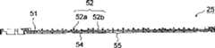
在平型压盘25的表面51上形成的肋52、56在馈纸方向延伸并且在垂直于馈纸方向的方向上对齐。馈送到平型压盘25上的纸张与肋52、56的上端接触并且被支撑在上面。肋52、56能够减少平型压盘25和纸张之间的接触面积,从而减少它们之间的摩擦并且帮助馈送纸张。The
肋52放置在平型压盘25的后部(在相对于馈纸方向的上游侧),该部分包括打印头31的介质传感器28所扫描的区域(图8中用D表示出)。肋56通过间隙57与肋52分开,并且放置在平型压盘25的前部(在相对于馈纸方向在下游侧)。在高度上肋56比肋52低。在平型压盘25上,肋56的数目比肋52的数目少。肋56位于在馈纸方向上从肋52延伸出来的线上,它们之间有间隙57。The
当在肋52上打印纸张时,纸张吸收墨并且下弯。在前后方向上上弯的纸张前沿穿过间隙57(图3和图5)以减少纸张的弯曲并且防止图像质量变坏。当纸张的前沿离开打印区域后,它滑到高度矮一些的肋56上,在这里减少了纸张在打印区域的下弯,并且纸张被平稳地输送。When paper is printed on the
图8是平型压盘25的平面图。在平型压盘25后部包括扫描区域D或介质传感器28的区域中形成了防反射处理部分51a,即在表面51上相对于馈纸方向的上游侧形成了由阴影示出的经过防反射处理的区域。从介质传感器28的光发射装置发出的光在平型压盘25或被输送纸张表面上被反射然后进入光接收装置。FIG. 8 is a plan view of the
但是,大部分光在平型压盘25的防反射处理部分51a处被漫反射和吸收。这样入射到光接收装置的光量非常低。因此就防止或减少了在平型压盘25上反射的光束。另一方面,大量从纸张上反射的光入射到光接收装置。因此,多功能设备1的一个控制部分(未示出)能够根据介质传感器28接收到的光量可靠地探测到纸张是否存在,从而精确地确定纸张的两个侧边。However, most of the light is diffusely reflected and absorbed at the anti-reflection treated portion 51 a of the
例如防反射处理部分51a的防反射处理可以通过进行不光滑处理(如喷砂处理和纹理处理)形成暗表面来实现。纹理处理是在被模制部分的表面上形成纹理图案的过程,它通过蚀刻使模制表面变粗糙。因此,当在模制平型压盘25的同时进行不光滑处理时,可以减少制造平型压盘25的过程数目。在这个实施例中,用Nihon-Etching有限公司的HM3013(不光滑处理加工图案)来形成纹理图案。For example, the anti-reflection treatment of the anti-reflection treatment portion 51a can be realized by performing a matte treatment such as sandblasting treatment and texture treatment to form a dark surface. Texturing is the process of forming a textured pattern on the surface of the part being molded, which roughens the molding surface by etching. Therefore, when the matte treatment is performed simultaneously with molding the
通过在介质传感器28的扫描区域D进行不光滑处理,介质传感器28的光发射装置发射出来的光在防反射处理部分51a漫反射。由于具有这种结构,减少了表面51的反射光量和光接收装置的接收光量,因此减小了介质传感器28在没有记录纸张位置处的探测误差。也就是说增加了介质传感器28探测纸张两个侧边的精度。这样就提高了在打印头31移动方向上的打印开始位置和打印结束位置的定位精度。By performing matte processing on the scanning area D of the
放置在平型压盘25两端的纸板40(图4)起到防止记录纸张向打印头31移动并且将记录纸张引导到平型压盘25上的作用。纸板40用薄金属形成,它放置在打印头31和平型压盘25之间的狭窄区域内。纸板41在介质传感器28的扫描区域D中形成凹陷40a(图4)以防止反射从光发射装置发出的光。平型压盘25在对应于凹陷40a的位置形成凹陷53,并且在限定凹陷53的侧壁上进行不光滑处理。因此可以控制在平型压盘25两端的光反射。Cardboards 40 ( FIG. 4 ) placed at both ends of the
肋53a沿着平型压盘25凹陷53的形状放置在与凹陷40a对应的位置,所以纸板40的边沿被肋53a覆盖。这种结构可以防止介质传感器28对纸张的两个侧边进行不正确的探测,如果介质传感器28的光发射装置发出的光束在任何一个纸板40的边沿被反射并且被光接收装置接收到就可能发生这种不正确的探测。通过利用防反射处理(如对肋53a进行不光滑处理),可以提高防止不正确探测的效果。The
优选防反射处理部分51a设在至少与标准纸张下部每个侧边附近对应的位置。如图11所示,这个位置在平型压盘25的区域51c内,平型压盘25的区域51c包括从纸张P侧边Pe向下垂直延伸的位置51b。It is preferable that the anti-reflection processing portion 51a is provided at a position corresponding to at least the vicinity of each side edge of the lower portion of the standard sheet. As shown in FIG. 11, this position is within an
标准尺寸的记录纸张包括图9所示的书信尺寸、A4尺寸、B5尺寸、A5尺寸、B6尺寸、明信片尺寸和照片的L尺寸,这些尺寸由JIS标准和北美标准规定。如果多功能设备1的尺寸较大,还可以使用B4尺寸和A3尺寸。Standard sizes of recording paper include letter size shown in FIG. 9, A4 size, B5 size, A5 size, B6 size, postcard size, and L size for photographs, which are specified by JIS standards and North American standards. If the size of the
当防反射处理部分51a形成在靠近标准尺寸纸张两个侧边的相反侧时,在打印通常使用的标准尺寸的记录纸张时,可以提高打印头31的定位精度。这时,能够根据在馈送纸张过程中的定位变化和光接收装置的灵敏度确定形成防反射处理部分51a的范围。When the anti-reflection processing portion 51a is formed on the opposite side near the two sides of the standard-sized paper, the positioning accuracy of the
例如可以根据设计规格,在相对于所要放置标准尺寸纸张两个侧边向外或向内的至少2mm的区域内提供防反射处理部分51a。这样即使记录纸张的位置有变化也能够防止探测两个侧边的误差。For example, the anti-reflection treatment portion 51a may be provided in an area of at least 2mm outward or inward relative to both sides of the standard size paper to be placed according to design specifications. This prevents errors in detection of both sides even if the position of the recording sheet varies.
如果在肋52顶表面纸张滑动的位置进行不光滑处理,肋52与纸张的摩擦力会增加,并且不能平稳地输送纸张。所以肋52的顶表面很容易反射光。如图9所示,布置肋52使得肋52的顶表面正好不在任何标准尺寸纸张两个侧边的下面。这样就减少了从肋52顶表面反射的光和光接收装置接收的光,在打印任何经常使用的标准尺寸纸张时都能够提高在打印头31移动方向上打印开始位置和打印结束位置的定位精度。If roughening is performed at the position where the paper slides on the top surface of the
如果布置肋52使得它靠近标准尺寸纸张两个侧边的外部,从光发射装置发出的、并且到达肋52的光可能由于被输送纸张位置和光接收装置灵敏度的变化而被光接收装置接收到。因此优选不在从任何标准尺寸纸张两个侧边正下方位置向外2mm内提供肋52。If the
肋52的高度为2mm或更高。因此能够减少从表面51反射的光量和在光接收装置处接收的光量。优选用任一种上述方法在表面51上形成防反射处理部分51a并且设定肋52的高度为2mm或更高。The height of the
如图6所示,肋52由具有不同高度的两种肋52a和52b构成。肋52a和52b在垂直于馈纸方向的方向上彼此平行放置。较高的肋52b与被打印的纸张滑动接触并且引导记录纸张。较低的肋52b支撑在打印过程中吸收了墨的并且在相对于馈纸方向的垂直方向上弯曲的纸张从而使之不与表面51接触。由于具有这种结构,可以防止纸张弯曲从而得到高打印质量。As shown in FIG. 6, the
当由于弯曲纸张侧边与表面51接触时,墨弄脏表面51并且粘附在纸张上。因此如图11所示,较低的肋52b放置在纸张P侧边Pa的内部,并且升高纸张的侧边以防止墨沾污在表面51上。When the sides of the paper come into contact with the
设在介质传感器28扫描区域D内的防反射处理部分51a的目的是减少或防止介质传感器28的光发射装置所发射的光在平型压盘25上反射然后在光接收装置处被接收。因此,可以使用粘贴在表面51上的具有片层形式的光吸收件来代替上述的不光滑处理。因此,从光发射装置发出的光束被光吸收件吸收,所以能够减小光束的反射。The purpose of the anti-reflection processing portion 51a provided in the scanning area D of the
也可以不使用不光滑处理或粘贴光吸收件,而是在被输送的标准尺寸纸张两个侧边附近的平型压盘25上形成开口。因此在打印标准尺寸的纸张时,从光发射装置发射的光能够穿过开口以防止光在平型压盘25上反射。It is also possible to form openings in the
另外,可以不使用不光滑处理或粘贴光吸收件,而是在平型压盘25上设有包括倾斜平面58a的凹槽部分58,如图12到14所示,凹槽部分58在介质传感器28的扫描区域内垂直于馈纸方向的方向上延伸。倾斜平面58a放置在介质传感器28的光发射装置发出的光的照射区域内,并且向馈纸方向倾斜。倾斜平面58a具有2mm到10mm的宽度并且其设计使得倾斜平面58a和介质传感器的光发射装置的入射光之间的夹角是20到70度。例如在示出的平型压盘25中,倾斜平面58a的长度是6mm,光发射装置的入射光形成的角度是45度。在这种形式下,优选倾斜平面58a是未经过不光滑处理或纹理处理的光滑平面。In addition, instead of using a matte finish or sticking a light absorbing member, a
通过形成具有这种倾斜平面58a的凹槽部分58,从介质传感器28的光发射装置发射的光在倾斜平面58a上反射。反射光行进的方向与介质传感器28的光接收装置所在的方向完全不同。由于具有这种结构,能够减少在平面51上反射的光和光接收装置接收的光,从而减少在没有记录介质存在的位置上的介质传感器28的探测误差。也就是说可以提高介质传感器28探测纸张两个侧边的精度。这样能够提高打印头31在移动方向上的打印开始位置和打印结束位置的定位精度。By forming the
通过在平型压盘25上形成凹槽部分58,可以保证薄板形式的平型压盘25的强度,并且可以防止平型压盘25在纵向的弯曲。因此,由于具有这种结构,可以去掉设在平型压盘25背侧的栅格型肋54或者为了简单将它们换成只在馈纸方向上延伸的肋。可以用多个在垂直于馈纸方向的方向上延伸的凹槽部分来代替肋54,它们在馈纸方向上彼此平行地设在平型压盘25上。这种形式也足以保证平型压盘25的强度。By forming the
在上面的结构中,包括倾斜平面58a的凹槽部分58形成在平型压盘25上的介质传感器28的扫描区域内。但是,如图15所示,可以在平型压盘25上的介质传感器28的扫描区域内形成包括倾斜平面59a的突出部分59。倾斜平面59a可以与倾斜平面58a具有同样的位置、同样的宽度和同样的倾斜角度,但是要将突出部分59的高度设定得比肋52低从而不会妨碍输送记录纸张。In the above structure, the
尽管已经参考了特殊的实施例描述了本发明,应该理解对实施例的描述是示意性的,不能认为它们限制了本发明的范围。对于本领域技术人员来讲无须偏离本发明的精神和范围就可以实现各种改进和改变。例如,如果所有可能在多功能设备1中使用的纸张尺寸都在图9中示出并且最小的尺寸是相片的L尺寸,那么在L尺寸的相片用纸通过的区域内就不必设有防反射处理部分51a、具有倾斜平面58a的凹槽部分58和具有倾斜平面59a的突出部分59,而只是将这些部分设在L尺寸的相片用纸的外面。如果所使用的纸张尺寸是有限的,可以将防反射处理部分51a、具有倾斜平面58a的凹槽部分58和具有倾斜平面59a的突出部分59设在预定区域内,即在纸张每个侧边外部大约2mm到5mm宽度范围内。While the invention has been described with reference to specific embodiments, it should be understood that the description of the embodiments is illustrative and they should not be taken as limiting the scope of the invention. Various modifications and changes will become apparent to those skilled in the art without departing from the spirit and scope of the invention. For example, if all possible paper sizes that can be used in the
根据本发明的实施例,平型压盘25的表面51上形成有防反射处理部分51a或倾斜平面58a或59a,从而减少或防止从光发射装置发出并由于反射被光接收装置接收到的光。这样就能够精确探测到纸张的两个侧边。因此能够精确定位打印头31并由此提供高打印质量。According to an embodiment of the present invention, an anti-reflection treatment portion 51a or an
通过不光滑处理、粘贴光吸收件、提供开口或形成倾斜平面58a、59a中的任何一种办法都能够很容易地对平型压盘25进行防反射处理。如果通过形成纹理的过程用形成纹理的办法来实现不光滑处理,可以在模制过程中对平型压盘25进行防反射处理。另外,可以通过与平型压盘25整体形成开口或倾斜平面58a、59a对平型压盘25进行防反射处理。可以在模塑成型中将开口、具有倾斜平面58a的凹槽部分58或具有倾斜平面59a的突出部分59与平型压盘25整体形成。The anti-reflection treatment of the
根据上面的实施例,提供肋52、56从而减小平型压盘25的表面51和纸张之间的接触面积,减小被输送纸张和平型压盘25之间的摩擦力,并且帮助输送纸张。肋52、56可以在模塑成型中与平型压盘25整体形成。According to the above embodiment, the
根据上面的实施例,肋52b从平型压盘25的表面51伸出2mm或更多,从而减少了从光发射装置发出、在肋52b被反射、最终被光接收装置接收的光量。According to the above embodiment, the
另外,在记录纸张两个侧边的正下方或两个侧边正下方位置向外2mm内的区域不设有肋。这样在打印具有通常使用尺寸的记录纸张时,能够减少从光发射装置发出、在肋处被反射、最终被光接收装置接收的光量。In addition, no ribs are provided in the area directly below the two sides of the recording paper or within 2 mm outward from the position directly below the two sides. This can reduce the amount of light emitted from the light-emitting means, reflected at the ribs, and finally received by the light-receiving means when printing recording paper having a size normally used.
肋由至少两种具有不同高度的肋52、56组成。高一些的肋52以低摩擦输送记录纸张,低一些的肋56输送在打印过程中吸收了墨并且部分弯曲的纸张以减少纸张的弯曲。由于具有这些肋,能够避免图像质量的变坏。The ribs consist of at least two
Claims (20)
Applications Claiming Priority (2)
| Application Number | Priority Date | Filing Date | Title |
|---|---|---|---|
| JP2003027687 | 2003-02-04 | ||
| JP027687/2003 | 2003-02-04 |
Publications (2)
| Publication Number | Publication Date |
|---|---|
| CN1519130Atrue CN1519130A (en) | 2004-08-11 |
| CN100344458C CN100344458C (en) | 2007-10-24 |
Family
ID=32984297
Family Applications (2)
| Application Number | Title | Priority Date | Filing Date |
|---|---|---|---|
| CNU2004200012640UExpired - LifetimeCN2755050Y (en) | 2003-02-04 | 2004-02-04 | Imager |
| CNB2004100036372AExpired - LifetimeCN100344458C (en) | 2003-02-04 | 2004-02-04 | Flat type disk pressuring and imaging appts. |
Family Applications Before (1)
| Application Number | Title | Priority Date | Filing Date |
|---|---|---|---|
| CNU2004200012640UExpired - LifetimeCN2755050Y (en) | 2003-02-04 | 2004-02-04 | Imager |
Country Status (2)
| Country | Link |
|---|---|
| US (1) | US6918709B2 (en) |
| CN (2) | CN2755050Y (en) |
Cited By (4)
| Publication number | Priority date | Publication date | Assignee | Title |
|---|---|---|---|---|
| CN100418866C (en)* | 2005-04-19 | 2008-09-17 | 精工爱普生株式会社 | printer |
| US8197056B2 (en) | 2007-01-26 | 2012-06-12 | Ricoh Company, Ltd. | Image forming apparatus having line-type recording head |
| CN102791492A (en)* | 2010-08-30 | 2012-11-21 | 日本电气英富醍株式会社 | Printer capable of preventing paper jam |
| US20210191306A1 (en)* | 2019-12-24 | 2021-06-24 | Hideki Tobinaga | Recording medium conveyance device and image forming apparatus incorporating the recording medium conveyance device |
Families Citing this family (19)
| Publication number | Priority date | Publication date | Assignee | Title |
|---|---|---|---|---|
| US6918709B2 (en)* | 2003-02-04 | 2005-07-19 | Brother Kogyo Kabushiki Kaisha | Flat platen and image forming apparatus |
| US7342689B2 (en)* | 2003-11-12 | 2008-03-11 | Transact Technologies Incorporated | Methods and apparatus for converting full color images to two-color images for printing at a two-color printer |
| JP4229021B2 (en)* | 2004-03-05 | 2009-02-25 | ブラザー工業株式会社 | Flat platen and ink jet recording apparatus using the same |
| JP2006110891A (en)* | 2004-10-15 | 2006-04-27 | Canon Inc | Recording device |
| DE602005019677D1 (en)* | 2004-12-22 | 2010-04-15 | Oce Tech Bv | Rack for printer of the float type |
| US20060284952A1 (en)* | 2005-06-20 | 2006-12-21 | Jin-Sheng Lai | Positioning device for a large ink-jet printer |
| US8079697B2 (en)* | 2005-10-14 | 2011-12-20 | Konica Minolta Medical & Graphic, Inc. | Inkjet recording apparatus and inkjet recording method |
| JP2007168125A (en)* | 2005-12-19 | 2007-07-05 | Brother Ind Ltd | Medium support member and image forming apparatus |
| JP4892389B2 (en)* | 2007-04-03 | 2012-03-07 | 株式会社ミマキエンジニアリング | Printer device |
| US20080247802A1 (en)* | 2007-04-04 | 2008-10-09 | Long Phong X | Starwheel |
| JP5067081B2 (en)* | 2007-08-31 | 2012-11-07 | セイコーエプソン株式会社 | Liquid ejection device |
| US8570516B2 (en)* | 2008-09-12 | 2013-10-29 | Cognex Corporation | Infrared direct illumination machine vision technique for semiconductor processing equipment |
| US7828287B2 (en)* | 2009-01-29 | 2010-11-09 | Dell Products L.P. | Printer star wheel |
| USD648784S1 (en)* | 2009-07-23 | 2011-11-15 | Provo Craft And Novelty, Inc. | Platen |
| JP5673944B2 (en) | 2011-02-28 | 2015-02-18 | セイコーエプソン株式会社 | Recording medium guide device and recording device |
| JP2017121704A (en)* | 2016-01-05 | 2017-07-13 | セイコーエプソン株式会社 | Liquid discharge device |
| US10329108B2 (en)* | 2017-08-25 | 2019-06-25 | Carestream Health, Inc. | System and method for detecting a media supply |
| JP7070025B2 (en)* | 2018-04-23 | 2022-05-18 | 京セラドキュメントソリューションズ株式会社 | Sensor unit and image forming device |
| JP7484274B2 (en)* | 2020-03-19 | 2024-05-16 | セイコーエプソン株式会社 | Printing device |
Family Cites Families (6)
| Publication number | Priority date | Publication date | Assignee | Title |
|---|---|---|---|---|
| JPS609031Y2 (en)* | 1978-06-26 | 1985-04-01 | 株式会社サト−研究所 | Printing device for hand labeler |
| US5127752A (en)* | 1991-01-09 | 1992-07-07 | Apple Computer, Inc. | Device and method of registering image relative to border of printed media |
| US5820283A (en)* | 1996-12-17 | 1998-10-13 | Hewlett-Packard Company | Print media handling system including dual incline support for controlling pen to paper spacing |
| JP4136124B2 (en) | 1998-10-03 | 2008-08-20 | キヤノンファインテック株式会社 | Method for detecting end position of recording paper using reflection type optical sensor and image forming apparatus |
| US6517269B1 (en)* | 2000-10-24 | 2003-02-11 | Hewlett-Packard Company | Narrow-width modular printing mechanism |
| US6918709B2 (en)* | 2003-02-04 | 2005-07-19 | Brother Kogyo Kabushiki Kaisha | Flat platen and image forming apparatus |
- 2004
- 2004-01-30USUS10/766,924patent/US6918709B2/ennot_activeExpired - Lifetime
- 2004-02-04CNCNU2004200012640Upatent/CN2755050Y/ennot_activeExpired - Lifetime
- 2004-02-04CNCNB2004100036372Apatent/CN100344458C/ennot_activeExpired - Lifetime
Cited By (7)
| Publication number | Priority date | Publication date | Assignee | Title |
|---|---|---|---|---|
| CN100418866C (en)* | 2005-04-19 | 2008-09-17 | 精工爱普生株式会社 | printer |
| US8197056B2 (en) | 2007-01-26 | 2012-06-12 | Ricoh Company, Ltd. | Image forming apparatus having line-type recording head |
| CN101229727B (en)* | 2007-01-26 | 2013-05-08 | 株式会社理光 | Image forming apparatus having line-type recording head |
| CN102791492A (en)* | 2010-08-30 | 2012-11-21 | 日本电气英富醍株式会社 | Printer capable of preventing paper jam |
| US8564795B2 (en) | 2010-08-30 | 2013-10-22 | Nec Infrontia Corporation | Printer capable of preventing paper jam |
| CN102791492B (en)* | 2010-08-30 | 2014-10-22 | 日本电气英富醍株式会社 | Printer capable of preventing paper jam |
| US20210191306A1 (en)* | 2019-12-24 | 2021-06-24 | Hideki Tobinaga | Recording medium conveyance device and image forming apparatus incorporating the recording medium conveyance device |
Also Published As
| Publication number | Publication date |
|---|---|
| CN100344458C (en) | 2007-10-24 |
| US20040183850A1 (en) | 2004-09-23 |
| US6918709B2 (en) | 2005-07-19 |
| CN2755050Y (en) | 2006-02-01 |
| HK1068584A1 (en) | 2005-04-29 |
Similar Documents
| Publication | Publication Date | Title |
|---|---|---|
| CN2755050Y (en) | Imager | |
| EP2116383B1 (en) | Conveying apparatus and recording apparatus | |
| JP5495682B2 (en) | Recording apparatus and recording method | |
| US7722026B2 (en) | Sheet conveyer device and image forming apparatus with error judging system | |
| CN1923648A (en) | Sheet supplying apparatus and image recording apparatus including the same | |
| CN2780467Y (en) | Conveying device of recording medium and imaging equipment including said device | |
| CN1736710A (en) | Inkjet recording device and control method for inkjet recording device | |
| JP3840153B2 (en) | Recording device | |
| JP2007268862A (en) | Recording device | |
| CN1583406A (en) | Recording apparatus | |
| US20080031671A1 (en) | Recording apparatus | |
| JP4409305B2 (en) | Flat platen and ink jet recording apparatus using the same | |
| CN1868755A (en) | Image input/output apparatus and method | |
| JP4779751B2 (en) | Image recording device | |
| HK1068584B (en) | Image forming apparatus | |
| JP2007119172A (en) | Recording device | |
| CN1874400A (en) | Scanner and image forming apparatus having the same | |
| CN1227571C (en) | Paper feeding device, image reading device and image forming device | |
| JP7484274B2 (en) | Printing device | |
| JP2012091914A (en) | Paper conveying device | |
| JP4147416B2 (en) | Recording material detection apparatus, recording apparatus, and liquid ejecting apparatus | |
| JP3679652B2 (en) | Automatic paper feeder and recording device | |
| US7905480B2 (en) | Job separator and image recording apparatus having the same | |
| JP3287622B2 (en) | Automatic paper feeder and recording device | |
| US7794039B2 (en) | Recording apparatus |
Legal Events
| Date | Code | Title | Description |
|---|---|---|---|
| C06 | Publication | ||
| PB01 | Publication | ||
| C10 | Entry into substantive examination | ||
| SE01 | Entry into force of request for substantive examination | ||
| REG | Reference to a national code | Ref country code:HK Ref legal event code:DE Ref document number:1068584 Country of ref document:HK | |
| C14 | Grant of patent or utility model | ||
| GR01 | Patent grant | ||
| REG | Reference to a national code | Ref country code:HK Ref legal event code:GR Ref document number:1068584 Country of ref document:HK | |
| CX01 | Expiry of patent term | Granted publication date:20071024 | |
| CX01 | Expiry of patent term |