CN1518209A - A Non-Correlation Adaptive Predistorter - Google Patents
A Non-Correlation Adaptive PredistorterDownload PDFInfo
- Publication number
- CN1518209A CN1518209ACNA2004100022011ACN200410002201ACN1518209ACN 1518209 ACN1518209 ACN 1518209ACN A2004100022011 ACNA2004100022011 ACN A2004100022011ACN 200410002201 ACN200410002201 ACN 200410002201ACN 1518209 ACN1518209 ACN 1518209A
- Authority
- CN
- China
- Prior art keywords
- look
- coupled
- predistortion
- signal
- phase
- Prior art date
- Legal status (The legal status is an assumption and is not a legal conclusion. Google has not performed a legal analysis and makes no representation as to the accuracy of the status listed.)
- Granted
Links
- 230000003044adaptive effectEffects0.000titleclaimsabstractdescription44
- 230000002596correlated effectEffects0.000claimsabstractdescription34
- 230000004044responseEffects0.000claimsabstractdescription9
- 238000000034methodMethods0.000claimsdescription20
- 238000001514detection methodMethods0.000claimsdescription7
- 230000008859changeEffects0.000claimsdescription3
- 230000001413cellular effectEffects0.000description7
- 238000004891communicationMethods0.000description4
- 238000000926separation methodMethods0.000description4
- 238000010586diagramMethods0.000description3
- 238000012545processingMethods0.000description3
- 230000009286beneficial effectEffects0.000description2
- 238000007620mathematical functionMethods0.000description2
- 230000001360synchronised effectEffects0.000description2
- 238000012546transferMethods0.000description2
- 230000003321amplificationEffects0.000description1
- 230000005540biological transmissionEffects0.000description1
- 230000010267cellular communicationEffects0.000description1
- 238000012512characterization methodMethods0.000description1
- 238000006243chemical reactionMethods0.000description1
- 230000008878couplingEffects0.000description1
- 238000010168coupling processMethods0.000description1
- 238000005859coupling reactionMethods0.000description1
- 230000003111delayed effectEffects0.000description1
- 230000001419dependent effectEffects0.000description1
- 230000000694effectsEffects0.000description1
- 238000005516engineering processMethods0.000description1
- 238000010295mobile communicationMethods0.000description1
- 238000012986modificationMethods0.000description1
- 230000004048modificationEffects0.000description1
- 238000003199nucleic acid amplification methodMethods0.000description1
- 230000009467reductionEffects0.000description1
- 230000001105regulatory effectEffects0.000description1
- 229920006395saturated elastomerPolymers0.000description1
- 238000007493shaping processMethods0.000description1
- 230000003595spectral effectEffects0.000description1
- 238000001228spectrumMethods0.000description1
Images

Classifications
- H—ELECTRICITY
- H03—ELECTRONIC CIRCUITRY
- H03F—AMPLIFIERS
- H03F1/00—Details of amplifiers with only discharge tubes, only semiconductor devices or only unspecified devices as amplifying elements
- H03F1/32—Modifications of amplifiers to reduce non-linear distortion
- H—ELECTRICITY
- H03—ELECTRONIC CIRCUITRY
- H03F—AMPLIFIERS
- H03F1/00—Details of amplifiers with only discharge tubes, only semiconductor devices or only unspecified devices as amplifying elements
- H03F1/32—Modifications of amplifiers to reduce non-linear distortion
- H03F1/3241—Modifications of amplifiers to reduce non-linear distortion using predistortion circuits
- H03F1/3247—Modifications of amplifiers to reduce non-linear distortion using predistortion circuits using feedback acting on predistortion circuits
- H—ELECTRICITY
- H03—ELECTRONIC CIRCUITRY
- H03F—AMPLIFIERS
- H03F1/00—Details of amplifiers with only discharge tubes, only semiconductor devices or only unspecified devices as amplifying elements
- H03F1/32—Modifications of amplifiers to reduce non-linear distortion
- H03F1/3241—Modifications of amplifiers to reduce non-linear distortion using predistortion circuits
- H03F1/3282—Acting on the phase and the amplitude of the input signal
- H03F1/3288—Acting on the phase and the amplitude of the input signal to compensate phase shift as a function of the amplitude
- H—ELECTRICITY
- H03—ELECTRONIC CIRCUITRY
- H03F—AMPLIFIERS
- H03F1/00—Details of amplifiers with only discharge tubes, only semiconductor devices or only unspecified devices as amplifying elements
- H03F1/32—Modifications of amplifiers to reduce non-linear distortion
- H03F1/3241—Modifications of amplifiers to reduce non-linear distortion using predistortion circuits
- H03F1/3294—Acting on the real and imaginary components of the input signal
- H—ELECTRICITY
- H04—ELECTRIC COMMUNICATION TECHNIQUE
- H04L—TRANSMISSION OF DIGITAL INFORMATION, e.g. TELEGRAPHIC COMMUNICATION
- H04L27/00—Modulated-carrier systems
- H04L27/32—Carrier systems characterised by combinations of two or more of the types covered by groups H04L27/02, H04L27/10, H04L27/18 or H04L27/26
- H04L27/34—Amplitude- and phase-modulated carrier systems, e.g. quadrature-amplitude modulated carrier systems
- H04L27/36—Modulator circuits; Transmitter circuits
- H04L27/366—Arrangements for compensating undesirable properties of the transmission path between the modulator and the demodulator
- H04L27/367—Arrangements for compensating undesirable properties of the transmission path between the modulator and the demodulator using predistortion
- H04L27/368—Arrangements for compensating undesirable properties of the transmission path between the modulator and the demodulator using predistortion adaptive predistortion
Landscapes
- Engineering & Computer Science (AREA)
- Physics & Mathematics (AREA)
- Nonlinear Science (AREA)
- Power Engineering (AREA)
- Computer Networks & Wireless Communication (AREA)
- Signal Processing (AREA)
- Amplifiers (AREA)
Abstract
Translated fromChinese
Description
Translated fromChinese技术领域technical field
本发明涉及放大器,特别是在这样的放大器中减少失真的技术。This invention relates to amplifiers, and more particularly to techniques for reducing distortion in such amplifiers.
背景技术Background technique
蜂窝网络内的无线通信服务通过各个地理区域或“蜂窝”来实现。传统上,蜂窝基站通常会包括蜂窝塔(cellular tower)和基础终端站(BTS),其中蜂窝塔具有与多个远程设备,例如蜂窝电话、寻呼设备相通信的射频天线。BTS通常包括一个或多个与将无线通讯信号传输到多个远程设备的射频天线相耦合的射频(RF)功率放大器。蜂窝网络可通过使用数字调制方案来提供服务。这些调制方案可以包括时分多址(TDMA)、码分多址(CDMA)、全球移动通信系统(GSM),及其他调制方案。Wireless communication services within a cellular network are provided through various geographic regions, or "cells." Traditionally, a cellular base station will usually include a cellular tower (cellular tower) and a basic terminal station (BTS), where the cellular tower has a radio frequency antenna that communicates with multiple remote devices, such as cellular phones, paging devices. A BTS typically includes one or more radio frequency (RF) power amplifiers coupled to radio frequency antennas that transmit wireless communication signals to a plurality of remote devices. Cellular networks may provide services by using digital modulation schemes. These modulation schemes may include Time Division Multiple Access (TDMA), Code Division Multiple Access (CDMA), Global System for Mobile Communications (GSM), and other modulation schemes.
在理论上或理想的RF功率放大器中,放大器的输出功率等于放大器的输入功率乘以一个常数(K),即放大或增益系数,并且该常数不会随着输入功率电平而变化。另外,该输出信号的相位与输入信号的相位相同。而实际上,输出的功率和相位都会作为输入信号的一个函数而变化。In a theoretical or ideal RF power amplifier, the amplifier's output power is equal to the amplifier's input power multiplied by a constant (K), the amplification or gain factor, and this constant does not vary with input power level. In addition, the phase of the output signal is the same as that of the input signal. In reality, both the output power and phase will vary as a function of the input signal.
通常,一个放大器具有三个操作区域。第一区域或线性区域,包括输入信号功率电平相对较小且K保持恒定的操作。在该线性区域中,放大器的响应非常接近于理想放大器。第二和第三区域被称为非线性区域。第二区域或压缩区域开始于输入功率电平增加到K随输入功率的进一步增加开始减少或者降低的地方。第三区域或饱和区域是随着输入功率的增加放大器的输出功率不再增加的区域。Typically, an amplifier has three regions of operation. The first region, or linear region, includes operation where the input signal power level is relatively small and K is kept constant. In this linear region, the response of the amplifier is very close to that of an ideal amplifier. The second and third regions are called non-linear regions. The second or compressed region begins when the input power level is increased to where K begins to decrease or decrease with further increases in input power. The third region, or saturation region, is the region where the output power of the amplifier no longer increases as the input power increases.
无线通信用户数量的持续增加引起了对RF频谱的需求增加,这就要求频谱效率更高的调制方案,例如前述的数字调制方案,和用于这些方案的更为有效的放大器。另外,为了延长电池寿命,蜂窝通信系统所使用的无线装置要求很高的功率效率。因此,这种系统中所使用的RF功率放大器往往在接近或位于非线性区域内操作以使效率最大化。The continued increase in the number of wireless communication users has created an increased demand for RF spectrum, which requires more spectrally efficient modulation schemes, such as the aforementioned digital modulation schemes, and more efficient amplifiers for these schemes. In addition, radio devices used in cellular communication systems require high power efficiency in order to extend battery life. Therefore, RF power amplifiers used in such systems tend to operate near or in the nonlinear region to maximize efficiency.
但是,当使用的数字调制方案具有起伏的包络(fluctuatingenvelope)时,在非线性区域附近的操作可能会导致操作的非线性。例如,在压缩区内操作可能会导致失真并且频谱扩展到相邻的信道。联邦通信委员会(FCC),像其他主管机构一样,限制在相邻信道内的发射。还可能会导致频带增宽和/或误码率的增加。主管机构通常也限制带外发射。在某些情况下,可能会减少一个系统中能够支持的通话数量。However, when the digital modulation scheme used has a fluctuating envelope, operation near the non-linear region may result in non-linear operation. For example, operating in the compressed region may cause distortion and spectral spread into adjacent channels. The Federal Communications Commission (FCC), like other regulatory agencies, restricts emissions on adjacent channels. It may also result in increased bandwidth and/or increased bit error rates. Authorities usually also restrict out-of-band emissions. In some cases, there may be a reduction in the number of calls that can be supported on a system.
因此,需要减少这种放大器响应的非线性以增加效率。为减少放大器的非线性而开发出的技术可以被归类为前馈(feed-forward)、反馈(feedback)或预失真(predistortion),它们分别具有各自的优点和缺点。Therefore, there is a need to reduce the non-linearity of the response of such amplifiers to increase efficiency. Techniques developed to reduce amplifier nonlinearity can be categorized as feed-forward, feedback, or predistortion, each with its own advantages and disadvantages.
前馈技术可衰减RF功率放大器输出信号的一部分,从而使输出信号具有与输入信号相同的电平。该失真的输出信号和输入信号之间的差被用于产生一个误差信号。然后该误差信号被放大并从RF功率放大器的输出中减去,从而提高了该RF功率放大器的线性。通常,前馈技术能够处理多载波信号,但在处理通常与RF功率放大器相关的漂移效应时效果不好。Feed-forward techniques attenuate a portion of the output signal of an RF power amplifier so that the output signal has the same level as the input signal. The difference between the distorted output signal and the input signal is used to generate an error signal. The error signal is then amplified and subtracted from the output of the RF power amplifier, thereby improving the linearity of the RF power amplifier. In general, feed-forward techniques are capable of handling multi-carrier signals, but are not effective at dealing with drift effects typically associated with RF power amplifiers.
反馈技术使用同步解调的输出信号作为反馈信息,以构成一个反馈环路。从输入信号中减去这些信号,产生环路误差信号。若反馈环路增益足够大,则环路误差信号可连续地校正RF功率放大器响应的任何非线性。通常,RF功率放大器中使用的反馈技术可减少带外发射,并且易于实施。然而,由于对环路延时的依赖,稳定性要求限制了带宽。因此,当使用某些调制方案时,反馈技术的应用受到限制。Feedback technology uses the output signal of synchronous demodulation as feedback information to form a feedback loop. These signals are subtracted from the input signal to produce the loop error signal. If the feedback loop gain is large enough, the loop error signal can continuously correct for any nonlinearity in the RF power amplifier's response. Typically, feedback techniques used in RF power amplifiers reduce out-of-band emissions and are easy to implement. However, stability requirements limit the bandwidth due to the dependence on loop delay. Therefore, the application of feedback techniques is limited when certain modulation schemes are used.
预失真技术向RF功率放大器提供适当的失真信号,使得RF功率放大器的输出是输入信号的一个按比例复制信号。一种类型的前置补偿器在放大器之前使用固定的信号预失真电路。但是,当使用具有波动包络的数字调制方案时,固定类型的前置补偿器的使用受到限制,并且还是不能解决所使用的RF功率放大器的变化或漂移。Predistortion techniques provide an appropriately distorted signal to the RF power amplifier so that the output of the RF power amplifier is a scaled replica of the input signal. One type of predistorter uses a fixed signal predistortion circuit before the amplifier. However, when using digital modulation schemes with fluctuating envelopes, the use of fixed-type predistorters is limited and still cannot account for variations or drifts of the RF power amplifier used.
另一种类型的前置补偿器是自适应前置补偿器。在一个自适应前置补偿器中,RF功率放大器的幅幅调制(AM-AM)和幅相调制(AM-PM)特性是利用数学技术,例如三次样条(cubic spline)插值,由使用来自RF功率放大器输出的同步解调而产生的失真值查找表(look-up table)来进行估计的。然后使用该估计值对RF功率放大器的输入信号进行预失真。自适应前置补偿器的性能通常可与负反馈和前馈技术相比,同时不会受调制系统的限制并且不会受漂移的影响。Another type of predistorter is an adaptive predistorter. In an adaptive predistorter, the amplitude modulation (AM-AM) and amplitude-phase modulation (AM-PM) characteristics of the RF power amplifier are determined using mathematical techniques, such as cubic spline (cubic spline) interpolation, by using from The distortion value look-up table (look-up table) produced by synchronous demodulation of RF power amplifier output is used for estimation. This estimate is then used to predistort the input signal to the RF power amplifier. The performance of an adaptive predistorter is generally comparable to negative feedback and feedforward techniques, while not being limited by the modulation system and not being affected by drift.
通常,这种自适应前置补偿器按以下方式操作。首先,数字信号或基带信号被编码为同相(I)和正交相位(Q)分量。然后I/Q分量通过一个脉冲整形滤波器以确保传输无符号间干扰(ISI)。随后I/Q信号被施加到一个矩形波形成电路,该电路可产生一表示基带输入信号功率的标量值(Vm)2。然后使用该标量值(Vm)2作为包含I/Q分量的预失真值的查找表的一个指针。随后将这些预失真值乘以I/Q分量,分别产生预失真的信号Id和Qd。然后将预失真的信号Id和Qd转换为模拟信号并施加到一个正交调制器。由一个振荡器驱动的该正交调制器产生一个施加到RF功率放大器的调制RF信号。Generally, such an adaptive predistorter operates as follows. First, a digital or baseband signal is encoded into in-phase (I) and quadrature-phase (Q) components. The I/Q components then pass through a pulse-shaping filter to ensure transmission without intersymbol interference (ISI). The I/Q signals are then applied to a square wave forming circuit which produces a scalar value (Vm)2 representing the power of the baseband input signal. This scalar value (Vm)2 is then used as a pointer to a look-up table containing predistortion values for the I/Q components. These predistortion values are then multiplied by the I/Q components to generate predistorted signalsId andQd , respectively. The predistorted signals Id and Qd are then converted to analog signals and applied to a quadrature modulator. The quadrature modulator, driven by an oscillator, produces a modulated RF signal that is applied to an RF power amplifier.
RF功率放大器输出的一部分被施加到由同一振荡器驱动的一正交解调器,以产生I/Q基带信号。该I/Q基带信号被转换为数字信号(I’/Q’)。然后分别比较I’/Q’和I/Q,以便估计RF功率放大器的AM-AM和AM-PM特性。由于预失真信号Id/Qd被施加到RF功率放大器和数字信号I’/Q’被产生的时刻之间会有时间延迟,因此输入信号I/Q在进行比较之前必须被延迟相同的时间量。这样,就比较I/Q信号而言,这种前置补偿器可以说是“相关的”和“自适应的”,“相关的”是因为在I/Q和I’/Q’之间存在一一对应的关系,“自适应的”是因为在查找表中的值随时间而变化。A portion of the RF power amplifier output is applied to a quadrature demodulator driven by the same oscillator to generate I/Q baseband signals. The I/Q baseband signals are converted into digital signals (I'/Q'). I'/Q' and I/Q are then compared, respectively, in order to estimate the AM-AM and AM-PM characteristics of the RF power amplifier. Since there is a time delay between the moment when the predistortion signalId /Qd is applied to the RF power amplifier and the moment when the digital signal I'/Q' is generated, the input signal I/Q must be delayed by the same amount of time before being compared quantity. Thus, such predistorters can be said to be "correlated" and "adaptive" in terms of comparing I/Q signals, "correlated" because between I/Q and I'/Q' there is A one-to-one relationship, "adaptive" because the values in the lookup table change over time.
这种相关的自适应前置补偿器可通过使用查找表中存储的值,利用三次样条插值法来估计对于(Vm)2值的AM-AM和AM-PM特性。三次样条插值法所能得到的精确的等同需要用于一个单独多项式拟合的高阶多项式。虽然三次样条插值法的使用或应用可以避免在RF功率放大器响应的线性化中对高阶多项式的需要,但由于其中使用的延时和解调电路,这种相关的自适应前置补偿器仍然是复杂和昂贵的。This correlated adaptive predistorter can utilize cubic spline interpolation to estimate the AM-AM and AM-PM characteristics for values of (Vm)2 by using values stored in a look-up table. The exact equivalence achievable by cubic spline interpolation requires higher order polynomials for a single polynomial fit. While the use or application of cubic spline interpolation can obviate the need for higher-order polynomials in the linearization of the RF power amplifier response, due to the delay and demodulation circuits used therein, such an associated adaptive predistorter Still complicated and expensive.
附图说明Description of drawings
并入并构成本发明一部分的附图,图示说明了本发明的实施例,并与下面给出的详细说明一起,用于说明本发明的原理。The accompanying drawings, which are incorporated in and constitute a part of this disclosure, illustrate embodiments of the invention and, together with the detailed description given below, serve to explain the principles of the invention.
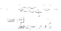
图1是根据本发明原理的非相关自适应前置补偿器的第一实施例的示意图;1 is a schematic diagram of a first embodiment of a non-correlated adaptive predistorter according to the principles of the present invention;
图2是根据本发明原理的非相关自适应前置补偿器的第二实施例的示意图;2 is a schematic diagram of a second embodiment of a non-correlated adaptive predistorter according to the principles of the present invention;
图3是根据本发明原理的非相关自适应前置补偿器的第三实施例的示意图。Fig. 3 is a schematic diagram of a third embodiment of a non-correlated adaptive predistorter in accordance with the principles of the present invention.
具体实施方式Detailed ways
参见图1-3,其中同样的标记表示同样的部分,图中示出了射频(RF)功率放大器和其使用的自适应前置补偿器。该自适应前置补偿器用于减少RF功率放大器响应的非线性,从而实现效率的增加,并减少设备复杂性和成本。更具体地,该自适应前置补偿器包括一输入环路和一输出环路,该输入环路包括一个含有多个预失真值的基于数字化的查找表(LUT),该输出环路用于测量RF功率放大器的交调(IM)失真产物,并相应地更新LUT预失真值。此外,可以使用样条函数来产生LUT中的值的优化集合,从而使输出环路中的RF功率放大器的IM失真产物最小化。Referring to Figures 1-3, where like numerals indicate like parts, a radio frequency (RF) power amplifier and an adaptive predistorter for use therewith are shown. The adaptive predistorter is used to reduce the non-linearity of the RF power amplifier response, thereby achieving an increase in efficiency and reducing device complexity and cost. More specifically, the adaptive predistorter includes an input loop including a digitized look-up table (LUT) containing a plurality of predistortion values, and an output loop for Measure the intermodulation (IM) distortion products of the RF power amplifier and update the LUT predistortion value accordingly. Furthermore, a spline function can be used to generate an optimized set of values in the LUT to minimize the IM distortion products of the RF power amplifier in the output loop.
首先参见图1,放大器系统的第一实施例20包括RF功率放大器10和非相关自适应前置补偿器12。RF功率放大器10是本领域技术人员公知的具有线性、压缩和饱和的操作区域的典型RF功率放大器。并且,RF功率放大器10可以是单信道或多信道放大器,或者是AB类(class AB)或B类(class B)放大器。Referring first to FIG. 1 , a
非相关的自适应前置补偿器12包括输入环路18和输出环路16。输入环路18包括包络检测电路22、LUT14、复数乘法器24、实电路和虚电路26、28、第一和第二数字-模拟转换器(DAC)30、32、正交调制器34,和RF振荡器36。输出环路16包括耦合器38、混频器40、本机振荡器42、放大器44、带通滤波器(BPF)46、检测器48、模拟-数字转换器(ADC)50,和处理器52。The non-correlated
如图1所示,输入环路18接收包含同相和正交相位分量I+jQ类型的输入信号,这里称作“基带信号”,并将信号I+jQ结合至包络检测电路22和复数乘法器24。包络检测电路22产生表示信号I+jQ的输入功率的单调增加函数例如功率、输入功率的对数、输入功率的平方根等的一个标量值,作为LUT14的一个索引。As shown in Figure 1,
LUT14包含信号I+jQ的同相(I)分量和正交相位(Q)分量的预失真值。LUT14中的初始值可以通过多种方式中的一种来确定。例如,可使用一校准例程来确定特定RF功率放大器的传输特性,并可据此确定LUT中的初始值。类似的,可以对特定系列或类型的RF功率放大器进行特征化,而LUT中的初始值可根据所产生的特征值来确定。特征化放大器性能和填充LUT的其他方法对本领域的技术人员来说都是显而易见的。
LUT14将初始预失真值结合至复数乘法器24,在复数乘法器中这些预失真值被乘以信号I+jQ,从而形成预失真的信号I’+jQ’。复数乘法器24还将预失真信号I’+jQ’的同相分量(I’)和正交相位分量(Q’)分别结合至如参考标记26和28所示的实电路(RE())和虚电路(IM())。本领域的技术人员将认识到,输入信号I+jQ的实部和虚部的分离通常在复数乘法器24中进行,然而,此处提供实电路(RE())和虚电路(IM())26、28,用于在特定实施例中需要附加额外的电路来进行分离时进一步说明。The
实电路和虚电路26、28将预失真信号I’+jQ’的同相分量(I’)和正交相位分量(Q’)分别耦合到第一和第二DAC30、32。第一和第二DAC30、32将数字信号I’+jQ’的实部(I’)和虚部(Q’)转换为模拟信号,并将该模拟信号结合至正交调制器34。Real and
与RF振荡器36相耦合的正交调制器34将模拟的I’和Q’信号调制到载波上,并将该载波结合至RF功率放大器10,表示为信号A’(t)cos[ω’t+θ’(t)]。RF功率放大器10将信号A’(t)cos[ω’t+θ’(t)]放大,并产生一输出信号,表示为RF OPT。该输出信号RF OPT可以被传送到天线,以便将数字的同相和正交相位信号I+jQ传送到无线设备。
现在参见输出环路16,RF功率放大器10的输出信号RF OPT的一部分被耦合器38送到混频器40。耦合器38可以是一个低损耗耦合器,从而在将输出信号RF OPT耦合到天线时功率损失量最小。本机振荡器42也被耦合到混频器40。Referring now to
本机振荡器42的频率被选择为,使混频器40将RF功率放大器10的交调失真产物,例如三阶交调失真产物(3rdIMD)耦合到放大器44。本领域的技术人员将认识到,本机振荡器可以是频率可调的或者可以被选择产生一个所需频率,从而可选出一个或多个所需的IM失真产物。并且,本领域的技术人员将认识到在某些实施例中可能不需要放大器44。The frequency of
例如,放大器44将RF功率放大器10的3rdIMD放大并耦合到BPF46。BPF46对RF功率放大器10的3rd IMD进行频率选择,并将3rd IMD结合至检测器48。检测器48产生表示3rd IMD的幅值的一个模拟信号并将其送到ADC50。如本领域的技术人员将认识到的,检测器48可以是一个二极管。ADC50将表示3rd IMD幅值的该模拟信号转换为数字信号,并将该数字信号结合至处理器52。For example,
处理器52利用梯度搜索,例如比较连续的3rd IMD幅度的值,来选择预失真值的一个优化集合,以使3rd IMD最小,从而提高RF功率放大器10响应的线性度。
处理器52也可以应用一个数学函数,例如样条函数来更新LUT14中的预失真值。本领域的技术人员在本公开说明的有益启示下可以很容易的想到样条函数的应用。这种样条函数的应用包括,分析幅度到幅度(AM-AM)和幅度到相位(AM-PM)的预失真曲线、分别参照RF功率放大器10的输入和输出,以及沿着LUT14的索引放置结点(knot)以最接近地比拟出RF功率放大器10的传输特性。本领域的技术人员将认识到在不脱离本发明精神的前提下也可以使用其它的数学函数。
对于RF功率放大器10,每个结点都只随幅值而变化。例如,在操作期间,改变每个结点的幅值、产生预失真值、然后测量3rd IMD以确定该结点幅值的改变是否改进了3rd IMD的性能。连续的执行该处理,从而提高RF功率放大器10的响应的线性度。For
在本发明的其他实施例中,沿着LUT索引进行的结点放置可以被改变。在这些实施例中,处理器,例如处理器52所执行的处理的复杂度基本上被增加了一倍。并且,在这些实施例中,可能存在一个结点子集,对于该结点子集,改变沿着LUT索引的放置是有利的。In other embodiments of the invention, the node placement along the LUT index can be changed. In these embodiments, the complexity of the processing performed by a processor, such as
本领域的技术人员将认识到,除了耦合器38、混频器40、本机振荡器42、放大器44、BPF46、检测器48、ADC50和处理器52之外的其他电子元件也可以根据需要使用,以便从RF功率放大器的输出中选择一个或多个交调失真产物。因此这里所示出的耦合器38、混频器40、本机振荡器42、放大器44、BPF46、检测器48、ADC50和处理器52是用于举例说明的目的,因此这些元件实际上仅是示例性的。Those skilled in the art will recognize that other electronic components in addition to
该实施例20可以被认为是一个开环电路结构,是绝对稳定的,开环路16的闭合仅仅是为了更新LUT14中的预失真值。并且,此实施例20是“自适应”的,因为该查找表中的预失真值是随时间而变化的。此实施例20还是“非相关的”,因为所施加的预失真值是基于先前的同相和正交相位信号的3rd IMD,而不像相关的自适应前置补偿器那样,是基于RF功率放大器将要放大的同相和正交相位信号。The
现在参见图2,图2示出了放大器系统的第二实施例20’。图2中的放大器系统20’类似于图1中的放大器系统20,其区别仅在于输入环路18’。因此,将只描述输入环路18’。在其它方面,正如本领域的技术人员所知,图2的实施例20’以类似于图1的实施例20的方式进行操作。Referring now to Figure 2, there is shown a second embodiment 20' of an amplifier system. Amplifier system 20' in Figure 2 is similar to
放大器系统20’包括RF功率放大器10和非相关自适应前置补偿器12’。非相关自适应前置补偿器12’包括输入环路18’和输出环路16。输入环路18’包括第一转换器电路(I/Q TO M/θ)54、LUT14’、乘法器电路56、加法器电路58、第二转换器电路(M’/θ’TO I’/Q’)60、实电路和虚电路26、28、第一和第二数字-模拟转换器(DAC)30、32、正交调制器34、和RF振荡器36。Amplifier system 20' includes
如图2所示,输入环路18’接收在这里同样被称作“基带信号”的包含同相和正交相位分量I+jQ类型的输入信号,并将信号I+jQ结合至第一转换器电路(I/Q TO M/θ)54。第一转换器电路(I/Q TO M/θ)54将信号I+jQ转换为幅值M和相位θ分量。幅值分量M被结合至乘法器电路56和LUT14’。相位分量θ被结合至加法器电路58。幅值分量M起到表示基带信号I+jQ的功率的一个标量值的作用,并可检索LUT14’。As shown in Figure 2, an input loop 18' receives an input signal of the type I+jQ, also referred to herein as a "baseband signal", comprising in-phase and quadrature-phase components, and combines the signal I+jQ to a first converter Circuit (I/Q TO M/θ)54. A first converter circuit (I/Q TO M/θ) 54 converts the signal I+jQ into magnitude M and phase θ components. The magnitude component M is combined to the multiplier circuit 56 and the LUT 14'. The phase component θ is combined to adder circuit 58 . The magnitude component M acts as a scalar value representing the power of the baseband signal I+jQ and can be retrieved from the LUT 14'.
LUT14’包含基带信号I+jQ的幅值和相位分量M,θ各自的预失真值G,φ。LUT14’将预失真值G,φ分别结合至乘法器电路56和加法器电路58,其中预失真值G,φ与信号I+jQ的幅值和相位分量M,θ相结合,形成预失真的幅值和相位分量M’,θ’。The LUT 14' contains the respective predistortion values G, φ of the magnitude and phase components M, θ of the baseband signal I+jQ. The LUT 14' combines the predistortion values G, φ to the multiplier circuit 56 and the adder circuit 58 respectively, wherein the predistortion values G, φ are combined with the amplitude and phase components M, θ of the signal I+jQ to form a predistortion Magnitude and phase components M', θ'.
乘法器电路56和加法器电路58将预失真的幅值和相位分量M’,θ’结合至第二转换器电路(M’/θ’TO I’/Q’)60。第二转换器电路(M’/θ’TO I’/Q’)60将预失真的幅值和相位分量M’,θ’转换为预失真信号I’+jQ′的同相分量I’和正交相位分量Q’。该同相分量I’和正交相位分量Q’被分别结合至实(RE())电路和虚(IM())电路26、28。本领域的技术人员将认识到,输入信号I+jQ实部和虚部的分离通常在第二转换器电路60中进行,然而,此处提供实电路(RE())和虚电路(IM())26,28,用于在特定实施例中需要附加额外的电路来进行分离时进一步说明。A multiplier circuit 56 and an adder circuit 58 combine the predistorted magnitude and phase components M', θ' to a second converter circuit (M'/θ' TO I'/Q') 60. The second converter circuit (M'/θ' TO I'/Q') 60 converts the predistorted amplitude and phase components M', θ' into the in-phase component I' and the positive component of the predistorted signal I'+jQ' Cross-phase component Q'. The in-phase component I' and quadrature-phase component Q' are coupled to real (RE()) and imaginary (IM())
图2所示的输入环路18’的剩余部分,即第一和第二DAC30、32、正交调制器34,和RF振荡器36,以类似于图1的输入环路18的方式进行操作。The remainder of input loop 18' shown in FIG. 2, namely first and
正如本领域的技术人员所认识到的,图1的放大器系统20和图2的放大器系统20’均对包含同相和正交相位分量的基带输入信号进行操作。然而,放大器系统20不同于放大器系统20’的是,图1的输入环路18对矩形波形式的输入信号(I/Q)进行操作,而图2的输入环路18’对极坐标形式的输入信号(M,θ)进行操作。因此,本发明并不依赖于任何特定形式的输入信号的处理。As will be appreciated by those skilled in the art,
现在参见图3,图3示出了放大器系统的第三实施例20”。图3中的放大器系统20”类似于图1和2中的放大器系统20和20’,其区别仅在于输入环路18”。因此,将只描述输入环路18”。在其它方面,图3的实施例20”以类似于图1和2的实施例20、20’的方式进行操作。Referring now to Figure 3, there is shown a
放大器系统20”包括RF功率放大器10和非相关自适应前置补偿器12”。非相关自适应前置补偿器12”包括输入环路18”和输出环路16。输入环路18”包括延时电路62、检测器电路64、模拟-数字转换器(ADC)66、复数衰减器68,和LUT14”。
如图1所示,输入环路18接收包含同相和正交相位分量I+jQ类型的输入信号,这里称作“基带信号”,并将信号I+jQ结合至包络检测电路22和复数乘法器24。As shown in Figure 1,
输入环路18”接收被表示为A(t)cos[ω(t)+θ(t)]类型的调制RF信号。信号A(t)cos[ω(t)+θ(t)]被结合至延时电路62和检测器电路64。检测器电路64产生表示信号A(t)cos[ω(t)+θ(t)]的功率的一个标量值A(t)。本领域技术人员将认识到检测器电路64的一个例子是二极管。检测器电路64被耦合到ADC66。ADC66将标量值A(t)转换为数字信号,该数字信号可作为LUT14”的一个索引。The
LUT14”包含输入信号A(t)cos[ω(t)+θ(t)]的幅值分量和相位分量的预失真值。LUT14”将这些预失真值结合至复数衰减器68,在复数衰减器68中这些预失真值作用于输入信号A(t)cos[ω(t)+θ(t)]的幅值分量和相位分量,形成预失真信号A’(t)cos[ω’(t)+θ’(t)]。延时电路62可允许充分的时间进行检测和转换,使得信号A(t)cos[ω(t)+θ(t)]与预失真值同时被结合至复数衰减器68。复数衰减器68将预失真信号A’(t)cos[ω’(t)+θ’(t)]结合至RF功率放大器10。
对本领域技术人员来说显而易见的是,与移相器相结合的功率衰减器可以作为一个复数衰减器。并且,对本领域技术人员来说同样显而易见的是,矢量调制器也可以被用作复数衰减器。It will be obvious to those skilled in the art that a power attenuator combined with a phase shifter can be used as a complex attenuator. Also, it is also obvious to those skilled in the art that a vector modulator can also be used as a complex attenuator.
正如本领域技术人员所知,图3的放大器系统20”对基于RF的或正弦的输入信号进行操作。因此不同于图1的输入环路18和图2的输入环路18’分别对矩形波形式(I/Q)和极坐标形式(M,θ)的输入信号进行操作,输入环路18”是对正弦信号进行操作的。因此,本发明并不局限于使用的输入信号的形式。As is known to those skilled in the art, the
尽管本发明已通过对其实施例的描述进行了举例说明,并且以相当详尽的方式进行了描述,但申请人的目的并不是为了将所附权利要求的保护范围以任何方式限制到这样的细节。例如,应当理解输入到非相关自适应前置补偿器的信号可以是多种形式中的任何一种,包括但并不局限于分别表示同相和正交相位分量以及表示调制载波信号的I+jQ类型和A(t)cos[ω(t)+θ(t)]类型。另外,可根据与这种信号相兼容来设计输入环路18、18’、18”。其他的优点和修改对本领域技术人员来说是显而易见的。因此,本发明在其更广义的方面并不局限于代表性装置和方法的特定细节,以及所示出并描述的例子。相应的,可以改变这些具体细节,而并不脱离申请人的广义发明概念的精神或范围。While the invention has been illustrated by the description of its embodiments and has been described in considerable detail, it is not the applicant's intention to limit the scope of the appended claims to such details in any way . For example, it should be understood that the signal input to the non-correlated adaptive predistorter may be in any of a variety of forms, including but not limited to I+jQ representing in-phase and quadrature-phase components, respectively, and representing the modulated carrier signal type and A(t)cos[ω(t)+θ(t)] type. Additionally, the
Claims (39)
Translated fromChineseApplications Claiming Priority (2)
| Application Number | Priority Date | Filing Date | Title |
|---|---|---|---|
| US10/342,633 | 2003-01-15 | ||
| US10/342,633US7403573B2 (en) | 2003-01-15 | 2003-01-15 | Uncorrelated adaptive predistorter |
Publications (2)
| Publication Number | Publication Date |
|---|---|
| CN1518209Atrue CN1518209A (en) | 2004-08-04 |
| CN100533956C CN100533956C (en) | 2009-08-26 |
Family
ID=31715554
Family Applications (1)
| Application Number | Title | Priority Date | Filing Date |
|---|---|---|---|
| CNB2004100022011AExpired - Fee RelatedCN100533956C (en) | 2003-01-15 | 2004-01-15 | Non-correlated adaptive predistorter and method and amplifier system incorporating such compensator |
Country Status (5)
| Country | Link |
|---|---|
| US (1) | US7403573B2 (en) |
| KR (1) | KR101107866B1 (en) |
| CN (1) | CN100533956C (en) |
| DE (1) | DE102004002239B4 (en) |
| GB (1) | GB2398683B (en) |
Cited By (47)
| Publication number | Priority date | Publication date | Assignee | Title |
|---|---|---|---|---|
| WO2009046627A1 (en)* | 2007-09-27 | 2009-04-16 | Lenovo (Beijing) Limited | A method for correcting signals in radio frequency links and the pre-distortion unit thereof |
| CN102150361A (en)* | 2007-12-07 | 2011-08-10 | 大力系统有限公司 | Baseband-derived RF digital predistortion |
| CN102340307A (en)* | 2011-10-09 | 2012-02-01 | 中国科学院微电子研究所 | Voltage-controlled oscillator device and method for calibrating the voltage-controlled oscillator |
| CN103095229A (en)* | 2013-01-22 | 2013-05-08 | 北京安迈泽成科技有限公司 | Radio frequency power amplifier |
| CN103296977A (en)* | 2011-11-30 | 2013-09-11 | 射频小型装置公司 | Monotonic conversion of RF power amplifier calibration data |
| US8811917B2 (en) | 2002-05-01 | 2014-08-19 | Dali Systems Co. Ltd. | Digital hybrid mode power amplifier system |
| CN104052414A (en)* | 2013-03-14 | 2014-09-17 | 亚德诺半导体技术公司 | Baseband Digital Pre-distortion Architecture |
| US8855234B2 (en) | 2006-12-26 | 2014-10-07 | Dali Systems Co. Ltd. | Method and system for baseband predistortion linearization in multi-channel wideband communications systems |
| US8878615B2 (en) | 2011-10-09 | 2014-11-04 | Institute of Microelectronics, Chinese Academy of Sciences | Voltage-controlled oscillator device and method of correcting voltage-controlled oscillator |
| CN104242834A (en)* | 2014-08-15 | 2014-12-24 | 中国舰船研究设计中心 | Nonlinear response modeling method of receiver preamplifier based on high-order polynomial fitting |
| US9178627B2 (en) | 2011-05-31 | 2015-11-03 | Rf Micro Devices, Inc. | Rugged IQ receiver based RF gain measurements |
| US9197256B2 (en) | 2012-10-08 | 2015-11-24 | Rf Micro Devices, Inc. | Reducing effects of RF mixer-based artifact using pre-distortion of an envelope power supply signal |
| US9197165B2 (en) | 2010-04-19 | 2015-11-24 | Rf Micro Devices, Inc. | Pseudo-envelope following power management system |
| US9197162B2 (en) | 2013-03-14 | 2015-11-24 | Rf Micro Devices, Inc. | Envelope tracking power supply voltage dynamic range reduction |
| US9203353B2 (en) | 2013-03-14 | 2015-12-01 | Rf Micro Devices, Inc. | Noise conversion gain limited RF power amplifier |
| US9207692B2 (en) | 2012-10-18 | 2015-12-08 | Rf Micro Devices, Inc. | Transitioning from envelope tracking to average power tracking |
| US9225231B2 (en) | 2012-09-14 | 2015-12-29 | Rf Micro Devices, Inc. | Open loop ripple cancellation circuit in a DC-DC converter |
| US9246460B2 (en) | 2011-05-05 | 2016-01-26 | Rf Micro Devices, Inc. | Power management architecture for modulated and constant supply operation |
| US9247496B2 (en) | 2011-05-05 | 2016-01-26 | Rf Micro Devices, Inc. | Power loop control based envelope tracking |
| US9250643B2 (en) | 2011-11-30 | 2016-02-02 | Rf Micro Devices, Inc. | Using a switching signal delay to reduce noise from a switching power supply |
| US9263996B2 (en) | 2011-07-20 | 2016-02-16 | Rf Micro Devices, Inc. | Quasi iso-gain supply voltage function for envelope tracking systems |
| US9280163B2 (en) | 2011-12-01 | 2016-03-08 | Rf Micro Devices, Inc. | Average power tracking controller |
| US9300252B2 (en) | 2013-01-24 | 2016-03-29 | Rf Micro Devices, Inc. | Communications based adjustments of a parallel amplifier power supply |
| US9298198B2 (en) | 2011-12-28 | 2016-03-29 | Rf Micro Devices, Inc. | Noise reduction for envelope tracking |
| US9374005B2 (en) | 2013-08-13 | 2016-06-21 | Rf Micro Devices, Inc. | Expanded range DC-DC converter |
| US9377797B2 (en) | 2011-12-01 | 2016-06-28 | Rf Micro Devices, Inc. | Multiple mode RF power converter |
| US9379667B2 (en) | 2011-05-05 | 2016-06-28 | Rf Micro Devices, Inc. | Multiple power supply input parallel amplifier based envelope tracking |
| US9401678B2 (en) | 2010-04-19 | 2016-07-26 | Rf Micro Devices, Inc. | Output impedance compensation of a pseudo-envelope follower power management system |
| US9431974B2 (en) | 2010-04-19 | 2016-08-30 | Qorvo Us, Inc. | Pseudo-envelope following feedback delay compensation |
| US9479118B2 (en) | 2013-04-16 | 2016-10-25 | Rf Micro Devices, Inc. | Dual instantaneous envelope tracking |
| US9484797B2 (en) | 2011-10-26 | 2016-11-01 | Qorvo Us, Inc. | RF switching converter with ripple correction |
| US9494962B2 (en) | 2011-12-02 | 2016-11-15 | Rf Micro Devices, Inc. | Phase reconfigurable switching power supply |
| US9515621B2 (en) | 2011-11-30 | 2016-12-06 | Qorvo Us, Inc. | Multimode RF amplifier system |
| US9614476B2 (en) | 2014-07-01 | 2017-04-04 | Qorvo Us, Inc. | Group delay calibration of RF envelope tracking |
| US9627975B2 (en) | 2012-11-16 | 2017-04-18 | Qorvo Us, Inc. | Modulated power supply system and method with automatic transition between buck and boost modes |
| CN106936434A (en)* | 2017-03-13 | 2017-07-07 | 中国电子科技集团公司第二十四研究所 | System is corrected based on the code density high-order harmonic wave that FFT is extracted |
| CN107070467A (en)* | 2015-11-03 | 2017-08-18 | 英飞凌科技股份有限公司 | Simulate RF predistorters and non-linear separator |
| US9813036B2 (en) | 2011-12-16 | 2017-11-07 | Qorvo Us, Inc. | Dynamic loadline power amplifier with baseband linearization |
| US9843294B2 (en) | 2015-07-01 | 2017-12-12 | Qorvo Us, Inc. | Dual-mode envelope tracking power converter circuitry |
| US9912297B2 (en) | 2015-07-01 | 2018-03-06 | Qorvo Us, Inc. | Envelope tracking power converter circuitry |
| US9954436B2 (en) | 2010-09-29 | 2018-04-24 | Qorvo Us, Inc. | Single μC-buckboost converter with multiple regulated supply outputs |
| US9973147B2 (en) | 2016-05-10 | 2018-05-15 | Qorvo Us, Inc. | Envelope tracking power management circuit |
| US10476437B2 (en) | 2018-03-15 | 2019-11-12 | Qorvo Us, Inc. | Multimode voltage tracker circuit |
| CN111108685A (en)* | 2017-08-11 | 2020-05-05 | 诺基亚通信公司 | Multi-phase digital signal predistortion in a radio transmitter |
| US11159129B2 (en) | 2002-05-01 | 2021-10-26 | Dali Wireless, Inc. | Power amplifier time-delay invariant predistortion methods and apparatus |
| CN113848380A (en)* | 2021-10-22 | 2021-12-28 | 深圳市兆驰数码科技股份有限公司 | Power detection circuit and method, and direct current and phase detection system and method |
| US20220295487A1 (en) | 2010-09-14 | 2022-09-15 | Dali Wireless, Inc. | Remotely reconfigurable distributed antenna system and methods |
Families Citing this family (36)
| Publication number | Priority date | Publication date | Assignee | Title |
|---|---|---|---|---|
| FR2846812B1 (en)* | 2002-11-05 | 2005-01-28 | Eads Defence & Security Ntwk | IMPROVING THE METHODS AND DEVICES FOR LEARNING A DEVICE FOR LINEARIZING AN RF AMPLIFIER |
| US20040198269A1 (en)* | 2002-12-30 | 2004-10-07 | Richard Phillips | Linearization of amplified feedback distortion |
| US7259630B2 (en)* | 2003-07-23 | 2007-08-21 | Andrew Corporation | Elimination of peak clipping and improved efficiency for RF power amplifiers with a predistorter |
| US7366252B2 (en)* | 2004-01-21 | 2008-04-29 | Powerwave Technologies, Inc. | Wideband enhanced digital injection predistortion system and method |
| US7336725B2 (en)* | 2004-03-03 | 2008-02-26 | Powerwave Technologies, Inc. | Digital predistortion system and method for high efficiency transmitters |
| JP2007536519A (en)* | 2004-05-04 | 2007-12-13 | ステノ コーポレイション | Double reference lock-in detector |
| ATE487272T1 (en)* | 2004-05-19 | 2010-11-15 | Ericsson Telefon Ab L M | ADAPTIVE PREDISTORTION METHOD AND ARRANGEMENT |
| US20060050810A1 (en)* | 2004-07-29 | 2006-03-09 | Interdigital Technology Corporation | Hybrid transmitter architecture having high efficiency and large dynamic range |
| KR100865886B1 (en)* | 2005-12-14 | 2008-10-29 | 삼성전자주식회사 | Device for compensating for nonlinearity in high frequency amplifiers |
| US7941109B2 (en)* | 2007-01-12 | 2011-05-10 | Panasonic Corporation | Polar modulation transmission apparatus and transmission power control method |
| JP4812643B2 (en)* | 2007-02-01 | 2011-11-09 | 株式会社日立国際電気 | Amplification equipment |
| US7957707B2 (en)* | 2007-03-30 | 2011-06-07 | Freescale Semiconductor, Inc. | Systems, apparatus and method for performing digital pre-distortion based on lookup table gain values |
| US8294516B2 (en)* | 2007-06-15 | 2012-10-23 | Broadcom Corporation | Power amplifier pre-distortion |
| US8369388B2 (en)* | 2007-06-15 | 2013-02-05 | Broadcom Corporation | Single-chip wireless tranceiver |
| US8194808B2 (en) | 2007-06-15 | 2012-06-05 | Broadcom Corporation | Carrier selection for multiple antennas |
| US8199857B2 (en)* | 2007-06-15 | 2012-06-12 | Broadcom Corporation | Apparatus to reconfigure an 802.11a/n transceiver to support 802.11j/10 MHz mode of operation |
| FR2930857A1 (en)* | 2008-04-30 | 2009-11-06 | Thales Sa | METHOD FOR CANCELING IMPERFECTIONS OF AN ANALOGUE SIGNAL GENERATED BY A DEVICE FOR MODULATING AN ANALOGUE SIGNAL FROM A DIGITAL MODULATION SIGNAL |
| TWI356582B (en)* | 2008-07-31 | 2012-01-11 | Ralink Technology Corp | Method for calibrating a power amplifier and devic |
| US7804359B1 (en)* | 2008-10-23 | 2010-09-28 | Scintera Networks, Inc. | Linearization with memory compensation |
| US8755756B1 (en) | 2009-04-29 | 2014-06-17 | Qualcomm Incorporated | Active cancellation of interference in a wireless communication system |
| US8207422B2 (en)* | 2009-05-11 | 2012-06-26 | Monsanto Technology Llc | Plants and seeds of hybrid corn variety CH201051 |
| US8331485B2 (en)* | 2009-07-08 | 2012-12-11 | Qualcomm Incorporated | Spur cancellation in a digital baseband transmit signal using cancelling tones |
| TWI407686B (en) | 2010-06-11 | 2013-09-01 | Realtek Semiconductor Corp | Compensation device applied to power amplifier, method for determining pre-distortion of power amplifier, and method for compensating linearity of power amplifier thereof |
| US8891715B2 (en) | 2011-02-16 | 2014-11-18 | Analog Devices, Inc. | Digital pre-distortion |
| US8885763B2 (en)* | 2011-02-16 | 2014-11-11 | Analog Devices, Inc. | Digital pre-distortion |
| US8615204B2 (en) | 2011-08-26 | 2013-12-24 | Qualcomm Incorporated | Adaptive interference cancellation for transmitter distortion calibration in multi-antenna transmitters |
| JP6080854B2 (en) | 2011-09-22 | 2017-02-15 | ダリ システムズ カンパニー リミテッド | System and method for increasing the bandwidth of digital predistortion in a multi-channel broadband communication system |
| WO2013134025A1 (en)* | 2012-03-04 | 2013-09-12 | Quantance, Inc. | Noise optimized envelope tracking system for power amplifiers |
| US8923787B2 (en)* | 2012-07-05 | 2014-12-30 | Pierre-André LAPORTE | Low sampling rate adaptation scheme for dual-band linearization |
| US8913689B2 (en) | 2012-09-24 | 2014-12-16 | Dali Systems Co. Ltd. | Wide bandwidth digital predistortion system with reduced sampling rate |
| FR3012704A1 (en)* | 2013-10-29 | 2015-05-01 | Chambre De Commerce Et D Ind De Region Paris Ile De France | LINEARIZATION METHOD BY DIGITAL PREDISTORSION |
| CN104836574B (en)* | 2015-04-30 | 2018-03-30 | 中国科学院微电子研究所 | Envelope tracking power amplifier structure capable of automatically aligning |
| TWI696344B (en)* | 2018-11-16 | 2020-06-11 | 財團法人工業技術研究院 | Linearity improving system and linearity improving method |
| US11381266B1 (en)* | 2020-12-31 | 2022-07-05 | Iridium Satellite Llc | Wireless communication with interference mitigation |
| WO2025013184A1 (en)* | 2023-07-10 | 2025-01-16 | 日本電信電話株式会社 | Wireless communication device, wireless communication method, and signal compensation program |
| WO2025013183A1 (en)* | 2023-07-10 | 2025-01-16 | 日本電信電話株式会社 | Wireless communication device, wireless communication method, and signal compensation program |
Family Cites Families (81)
| Publication number | Priority date | Publication date | Assignee | Title |
|---|---|---|---|---|
| US3241078A (en)* | 1963-06-18 | 1966-03-15 | Honeywell Inc | Dual output synchronous detector utilizing transistorized differential amplifiers |
| US3689752A (en)* | 1970-04-13 | 1972-09-05 | Tektronix Inc | Four-quadrant multiplier circuit |
| US4156283A (en)* | 1972-05-30 | 1979-05-22 | Tektronix, Inc. | Multiplier circuit |
| FR2520957A1 (en) | 1982-01-29 | 1983-08-05 | Thomson Csf | DEVICE FOR CORRECTING INTERMODULATION PRODUCED BY A HIGH-FREQUENCY CONTROLLED SIGNAL AMPLIFIER |
| DE3614785A1 (en)* | 1986-05-02 | 1988-01-21 | Rohde & Schwarz | AUXILIARY SYSTEM FOR EQUALIZING FREQUENCY-DEPENDENT NON-LINEAR SYSTEMS, IN PARTICULAR AMPLIFIERS |
| ES2045047T3 (en)* | 1988-08-31 | 1994-01-16 | Siemens Ag | MULTIPLIER WITH FOUR QUADRANTS OF MULTIPLE INPUTS. |
| US4879519A (en)* | 1988-10-31 | 1989-11-07 | American Telephone And Telegraph Company, At&T Bell Labs | Predistortion compensated linear amplifier |
| US4885551A (en) | 1988-10-31 | 1989-12-05 | American Telephone And Telegraph Company At&T Bell Laboratories | Feed forward linear amplifier |
| US4978873A (en)* | 1989-10-11 | 1990-12-18 | The United States Of America As Represented By The Secretary Of The Navy | CMOS analog four-quadrant multiplier |
| GB2238195A (en)* | 1989-11-16 | 1991-05-22 | Motorola Inc | Feed forward amplifier with pilot tone cancellation |
| US5023565A (en)* | 1990-01-26 | 1991-06-11 | At&T Bell Laboratories | Linear amplifier with automatic adjustment of feed forward loop gain and phase |
| US5049832A (en)* | 1990-04-20 | 1991-09-17 | Simon Fraser University | Amplifier linearization by adaptive predistortion |
| US5119040A (en)* | 1991-01-04 | 1992-06-02 | Motorola, Inc. | Method and apparatus for optimizing the performance of a power amplifier circuit |
| US5130663A (en)* | 1991-04-15 | 1992-07-14 | Motorola, Inc. | Feed forward amplifier network with frequency swept pilot tone |
| US5477187A (en)* | 1992-03-19 | 1995-12-19 | Fujitsu Limited | Feed forward amplifier |
| US5325095A (en)* | 1992-07-14 | 1994-06-28 | The United States Of America As Represented By The United States Department Of Energy | Stepped frequency ground penetrating radar |
| GB9307384D0 (en)* | 1993-04-08 | 1993-06-02 | Philips Electronics Uk Ltd | Four quadrant multiplier and a receiver including such a circuit |
| US5485120A (en) | 1994-07-28 | 1996-01-16 | Aval Communications Inc. | Feed-forward power amplifier system with adaptive control and control method |
| US5610554A (en)* | 1994-07-28 | 1997-03-11 | Aval Communications Inc. | Cancellation loop, for a feed-forward amplifier, employing an adaptive controller |
| JP2697625B2 (en)* | 1994-08-31 | 1998-01-14 | 日本電気株式会社 | Feedforward amplifier |
| US5491454A (en)* | 1994-10-31 | 1996-02-13 | Motorola, Inc. | Method and apparatus for reducing distortion in an output signal of an amplifier |
| US5528196A (en)* | 1995-01-06 | 1996-06-18 | Spectrian, Inc. | Linear RF amplifier having reduced intermodulation distortion |
| JP3360464B2 (en)* | 1995-02-13 | 2002-12-24 | 松下電器産業株式会社 | Feed forward amplifier |
| JP2967699B2 (en)* | 1995-03-06 | 1999-10-25 | 日本電気株式会社 | Transmission device |
| JP3320284B2 (en)* | 1995-04-18 | 2002-09-03 | 富士通株式会社 | FEED FORWARD AMPLIFIER, CONTROL METHOD OF FEED FORWARD AMPLIFIER, AND BASE STATION WITH FEED FORWARD AMPLIFIER |
| AU7462896A (en) | 1995-08-23 | 1997-03-19 | Motorola, Inc. | Wideband power amplifier control systems |
| US5621354A (en)* | 1995-10-17 | 1997-04-15 | Motorola, Inc. | Apparatus and method for performing error corrected amplification in a radio frequency system |
| RU2142670C1 (en)* | 1995-11-16 | 1999-12-10 | Самсунг Электроникс Ко., Лтд. | Device for linear power amplification |
| US5732333A (en)* | 1996-02-14 | 1998-03-24 | Glenayre Electronics, Inc. | Linear transmitter using predistortion |
| US5892397A (en)* | 1996-03-29 | 1999-04-06 | Spectrian | Adaptive compensation of RF amplifier distortion by injecting predistortion signal derived from respectively different functions of input signal amplitude |
| US5760646A (en)* | 1996-03-29 | 1998-06-02 | Spectrian | Feed-forward correction loop with adaptive predistortion injection for linearization of RF power amplifier |
| US6064250A (en)* | 1996-07-29 | 2000-05-16 | Townsend And Townsend And Crew Llp | Various embodiments for a low power adaptive charge pump circuit |
| FR2752313B1 (en)* | 1996-08-07 | 1998-11-13 | Alcatel Telspace | METHOD AND DEVICE FOR MODELING THE AM / AM AND AM / PM CHARACTERISTICS OF AN AMPLIFIER, AND CORRESPONDING PREDISTORSION METHOD |
| US5862459A (en)* | 1996-08-27 | 1999-01-19 | Telefonaktiebolaget Lm Ericsson | Method of and apparatus for filtering intermodulation products in a radiocommunication system |
| JPH10145161A (en)* | 1996-11-13 | 1998-05-29 | Nec Corp | Pre-distortion automatic adjustment circuit |
| US5933766A (en)* | 1996-12-16 | 1999-08-03 | Ericsson Inc. | Intermodulation compensation in multi-channel amplifiers |
| US6091715A (en)* | 1997-01-02 | 2000-07-18 | Dynamic Telecommunications, Inc. | Hybrid radio transceiver for wireless networks |
| US6208846B1 (en)* | 1997-01-13 | 2001-03-27 | Lucent Technologies, Inc. | Method and apparatus for enhancing transmitter circuit efficiency of mobile radio units by selectable switching of power amplifier |
| US5808512A (en)* | 1997-01-31 | 1998-09-15 | Ophir Rf, Inc. | Feed forward amplifiers and methods |
| US5923712A (en)* | 1997-05-05 | 1999-07-13 | Glenayre Electronics, Inc. | Method and apparatus for linear transmission by direct inverse modeling |
| US5867065A (en)* | 1997-05-07 | 1999-02-02 | Glenayre Electronics, Inc. | Frequency selective predistortion in a linear transmitter |
| US5900778A (en)* | 1997-05-08 | 1999-05-04 | Stonick; John T. | Adaptive parametric signal predistorter for compensation of time varying linear and nonlinear amplifier distortion |
| US6072364A (en)* | 1997-06-17 | 2000-06-06 | Amplix | Adaptive digital predistortion for power amplifiers with real time modeling of memoryless complex gains |
| US5959499A (en)* | 1997-09-30 | 1999-09-28 | Motorola, Inc. | Predistortion system and method using analog feedback loop for look-up table training |
| US5831478A (en)* | 1997-09-30 | 1998-11-03 | Motorola, Inc. | Feedforward amplifier |
| US5923214A (en)* | 1997-12-17 | 1999-07-13 | Motorola, Inc. | Feedforward amplifier network with swept pilot tone for reducing distortion generated by a power amplifier |
| US6075411A (en)* | 1997-12-22 | 2000-06-13 | Telefonaktiebolaget Lm Ericsson | Method and apparatus for wideband predistortion linearization |
| US5912586A (en)* | 1997-12-23 | 1999-06-15 | Motorola, Inc. | Feed forward amplifier with digital intermodulation control |
| US6125266A (en)* | 1997-12-31 | 2000-09-26 | Nokia Mobile Phones Limited | Dual band architectures for mobile stations having transmitter linearization feedback |
| US6078216A (en)* | 1998-03-31 | 2000-06-20 | Spectrian Corporation | Aliased wide band performance monitor for adjusting predistortion and vector modulator control parameters of RF amplifier |
| US6160996A (en) | 1998-03-31 | 2000-12-12 | Lucent Technologies Inc. | Method for adaptively controlling amplifier linearization devices |
| US6285251B1 (en) | 1998-04-02 | 2001-09-04 | Ericsson Inc. | Amplification systems and methods using fixed and modulated power supply voltages and buck-boost control |
| JP3058269B2 (en)* | 1998-04-08 | 2000-07-04 | 日本電気株式会社 | Mobile phone equipment |
| US6046635A (en)* | 1998-04-08 | 2000-04-04 | Powerwave Technologies, Inc. | Dynamic predistortion compensation for a power amplifier |
| US6101225A (en)* | 1998-04-29 | 2000-08-08 | Motorola, Inc. | Method and apparatus for performing a modulation |
| US6600792B2 (en)* | 1998-06-26 | 2003-07-29 | Qualcomm Incorporated | Predistortion technique for high power amplifiers |
| US6236837B1 (en)* | 1998-07-30 | 2001-05-22 | Motorola, Inc. | Polynomial Predistortion linearizing device, method, phone and base station |
| US6052023A (en)* | 1998-08-31 | 2000-04-18 | Lucent Technologies Inc. | Calibration system for feed forward distortion reduction system |
| US6493543B1 (en) | 1998-10-19 | 2002-12-10 | Powerwave Technologies, Inc. | Multichannel amplification system using mask detection |
| US6144255A (en)* | 1998-10-19 | 2000-11-07 | Powerwave Technologies, Inc. | Feedforward amplification system having mask detection compensation |
| US6118339A (en)* | 1998-10-19 | 2000-09-12 | Powerwave Technologies, Inc. | Amplification system using baseband mixer |
| US6154641A (en)* | 1998-10-27 | 2000-11-28 | Lucent Technologies Inc. | Wideband multiple channel frequency converter |
| US6275685B1 (en)* | 1998-12-10 | 2001-08-14 | Nortel Networks Limited | Linear amplifier arrangement |
| US5986499A (en)* | 1998-12-21 | 1999-11-16 | Lucent Technologies Inc. | Pilot signal detection system using band reject filter |
| US6236267B1 (en)* | 1998-12-29 | 2001-05-22 | International Business Machines Corporation | Linearization for power amplifiers using feed-forward and feedback control |
| GB2347031B (en) | 1999-02-12 | 2001-03-21 | Wireless Systems Int Ltd | Signal processing means |
| US6104239A (en)* | 1999-03-12 | 2000-08-15 | Thomcast Communications, Inc. | Method for correcting frequency-varying nonlinear errors and digital correction circuit implementing same |
| US6118335A (en)* | 1999-05-06 | 2000-09-12 | Nortel Networks Corporation | Method and apparatus for providing adaptive predistortion in power amplifier and base station utilizing same |
| US6342810B1 (en)* | 1999-07-13 | 2002-01-29 | Pmc-Sierra, Inc. | Predistortion amplifier system with separately controllable amplifiers |
| US6356146B1 (en)* | 1999-07-13 | 2002-03-12 | Pmc-Sierra, Inc. | Amplifier measurement and modeling processes for use in generating predistortion parameters |
| US6157253A (en)* | 1999-09-03 | 2000-12-05 | Motorola, Inc. | High efficiency power amplifier circuit with wide dynamic backoff range |
| US6694385B1 (en)* | 1999-09-10 | 2004-02-17 | Texas Instruments Incorporated | Configuration bus reconfigurable/reprogrammable interface for expanded direct memory access processor |
| US6285255B1 (en)* | 1999-11-02 | 2001-09-04 | Harris Corporation | Adaptive compensation for carrier signal phase distortion |
| US6304140B1 (en)* | 2000-06-12 | 2001-10-16 | Motorola, Inc. | Digital predistortion for amplifiers |
| US6359508B1 (en)* | 2000-08-17 | 2002-03-19 | Spectrian Corporation | Distortion detection apparatus for controlling predistortion, carrier cancellation and feed-forward cancellation in linear RF power amplifiers |
| JP3590571B2 (en) | 2000-08-30 | 2004-11-17 | 株式会社日立国際電気 | Distortion compensator |
| JP2002151973A (en) | 2000-11-13 | 2002-05-24 | Matsushita Electric Ind Co Ltd | Transmission device and pre-distortion distortion compensation method |
| GB2369735B (en) | 2000-12-02 | 2004-07-14 | Roke Manor Research | Method of linearising a signal |
| GB2376584B (en) | 2001-06-15 | 2005-02-16 | Wireless Systems Int Ltd | Signal correction techniques |
| JP2003273659A (en)* | 2002-03-15 | 2003-09-26 | Hitachi Kokusai Electric Inc | Distortion compensation amplifier |
| US7333561B2 (en)* | 2002-06-28 | 2008-02-19 | Motorola, Inc. | Postdistortion amplifier with predistorted postdistortion |
- 2003
- 2003-01-15USUS10/342,633patent/US7403573B2/ennot_activeExpired - Fee Related
- 2004
- 2004-01-09KRKR1020040001478Apatent/KR101107866B1/ennot_activeExpired - Fee Related
- 2004-01-12GBGB0400583Apatent/GB2398683B/ennot_activeExpired - Fee Related
- 2004-01-15CNCNB2004100022011Apatent/CN100533956C/ennot_activeExpired - Fee Related
- 2004-01-15DEDE102004002239.9Apatent/DE102004002239B4/ennot_activeExpired - Fee Related
Cited By (67)
| Publication number | Priority date | Publication date | Assignee | Title |
|---|---|---|---|---|
| US8811917B2 (en) | 2002-05-01 | 2014-08-19 | Dali Systems Co. Ltd. | Digital hybrid mode power amplifier system |
| US11418155B2 (en) | 2002-05-01 | 2022-08-16 | Dali Wireless, Inc. | Digital hybrid mode power amplifier system |
| US11159129B2 (en) | 2002-05-01 | 2021-10-26 | Dali Wireless, Inc. | Power amplifier time-delay invariant predistortion methods and apparatus |
| US9246731B2 (en) | 2006-12-26 | 2016-01-26 | Dali Systems Co. Ltd. | Method and system for baseband predistortion linearization in multi-channel wideband communication systems |
| US11129076B2 (en) | 2006-12-26 | 2021-09-21 | Dali Wireless, Inc. | Method and system for baseband predistortion linearization in multi-channel wideband communication systems |
| US9913194B2 (en) | 2006-12-26 | 2018-03-06 | Dali Wireless, Inc. | Method and system for baseband predistortion linearization in multi-channel wideband communication systems |
| US8855234B2 (en) | 2006-12-26 | 2014-10-07 | Dali Systems Co. Ltd. | Method and system for baseband predistortion linearization in multi-channel wideband communications systems |
| WO2009046627A1 (en)* | 2007-09-27 | 2009-04-16 | Lenovo (Beijing) Limited | A method for correcting signals in radio frequency links and the pre-distortion unit thereof |
| US8451925B2 (en) | 2007-09-27 | 2013-05-28 | Lenovo (Beijing) Limited | Method and pre-corrector for correcting signals in radio frequency links |
| US8548403B2 (en) | 2007-12-07 | 2013-10-01 | Dali Systems Co., Ltd. | Baseband-derived RF digital predistortion |
| CN102150361B (en)* | 2007-12-07 | 2016-11-09 | 大力系统有限公司 | Baseband-derived RF digital predistortion |
| CN102150361A (en)* | 2007-12-07 | 2011-08-10 | 大力系统有限公司 | Baseband-derived RF digital predistortion |
| US9768739B2 (en) | 2008-03-31 | 2017-09-19 | Dali Systems Co. Ltd. | Digital hybrid mode power amplifier system |
| US9621113B2 (en) | 2010-04-19 | 2017-04-11 | Qorvo Us, Inc. | Pseudo-envelope following power management system |
| US9197165B2 (en) | 2010-04-19 | 2015-11-24 | Rf Micro Devices, Inc. | Pseudo-envelope following power management system |
| US9401678B2 (en) | 2010-04-19 | 2016-07-26 | Rf Micro Devices, Inc. | Output impedance compensation of a pseudo-envelope follower power management system |
| US9431974B2 (en) | 2010-04-19 | 2016-08-30 | Qorvo Us, Inc. | Pseudo-envelope following feedback delay compensation |
| US20220295487A1 (en) | 2010-09-14 | 2022-09-15 | Dali Wireless, Inc. | Remotely reconfigurable distributed antenna system and methods |
| US11805504B2 (en) | 2010-09-14 | 2023-10-31 | Dali Wireless, Inc. | Remotely reconfigurable distributed antenna system and methods |
| US9954436B2 (en) | 2010-09-29 | 2018-04-24 | Qorvo Us, Inc. | Single μC-buckboost converter with multiple regulated supply outputs |
| US9247496B2 (en) | 2011-05-05 | 2016-01-26 | Rf Micro Devices, Inc. | Power loop control based envelope tracking |
| US9379667B2 (en) | 2011-05-05 | 2016-06-28 | Rf Micro Devices, Inc. | Multiple power supply input parallel amplifier based envelope tracking |
| US9246460B2 (en) | 2011-05-05 | 2016-01-26 | Rf Micro Devices, Inc. | Power management architecture for modulated and constant supply operation |
| US9178627B2 (en) | 2011-05-31 | 2015-11-03 | Rf Micro Devices, Inc. | Rugged IQ receiver based RF gain measurements |
| US9263996B2 (en) | 2011-07-20 | 2016-02-16 | Rf Micro Devices, Inc. | Quasi iso-gain supply voltage function for envelope tracking systems |
| US8878615B2 (en) | 2011-10-09 | 2014-11-04 | Institute of Microelectronics, Chinese Academy of Sciences | Voltage-controlled oscillator device and method of correcting voltage-controlled oscillator |
| CN102340307A (en)* | 2011-10-09 | 2012-02-01 | 中国科学院微电子研究所 | Voltage-controlled oscillator device and method for calibrating the voltage-controlled oscillator |
| US9484797B2 (en) | 2011-10-26 | 2016-11-01 | Qorvo Us, Inc. | RF switching converter with ripple correction |
| US9515621B2 (en) | 2011-11-30 | 2016-12-06 | Qorvo Us, Inc. | Multimode RF amplifier system |
| US9250643B2 (en) | 2011-11-30 | 2016-02-02 | Rf Micro Devices, Inc. | Using a switching signal delay to reduce noise from a switching power supply |
| CN103296977B (en)* | 2011-11-30 | 2016-07-06 | 射频小型装置公司 | The monotonic transitions of RF power amplifier calibration data |
| CN103296977A (en)* | 2011-11-30 | 2013-09-11 | 射频小型装置公司 | Monotonic conversion of RF power amplifier calibration data |
| US9280163B2 (en) | 2011-12-01 | 2016-03-08 | Rf Micro Devices, Inc. | Average power tracking controller |
| US9377797B2 (en) | 2011-12-01 | 2016-06-28 | Rf Micro Devices, Inc. | Multiple mode RF power converter |
| US9494962B2 (en) | 2011-12-02 | 2016-11-15 | Rf Micro Devices, Inc. | Phase reconfigurable switching power supply |
| US9813036B2 (en) | 2011-12-16 | 2017-11-07 | Qorvo Us, Inc. | Dynamic loadline power amplifier with baseband linearization |
| US9298198B2 (en) | 2011-12-28 | 2016-03-29 | Rf Micro Devices, Inc. | Noise reduction for envelope tracking |
| US9225231B2 (en) | 2012-09-14 | 2015-12-29 | Rf Micro Devices, Inc. | Open loop ripple cancellation circuit in a DC-DC converter |
| US9197256B2 (en) | 2012-10-08 | 2015-11-24 | Rf Micro Devices, Inc. | Reducing effects of RF mixer-based artifact using pre-distortion of an envelope power supply signal |
| US9207692B2 (en) | 2012-10-18 | 2015-12-08 | Rf Micro Devices, Inc. | Transitioning from envelope tracking to average power tracking |
| US9627975B2 (en) | 2012-11-16 | 2017-04-18 | Qorvo Us, Inc. | Modulated power supply system and method with automatic transition between buck and boost modes |
| CN103095229B (en)* | 2013-01-22 | 2016-04-06 | 宜确半导体(苏州)有限公司 | Radio-frequency power amplifier |
| CN103095229A (en)* | 2013-01-22 | 2013-05-08 | 北京安迈泽成科技有限公司 | Radio frequency power amplifier |
| US9300252B2 (en) | 2013-01-24 | 2016-03-29 | Rf Micro Devices, Inc. | Communications based adjustments of a parallel amplifier power supply |
| US9929696B2 (en) | 2013-01-24 | 2018-03-27 | Qorvo Us, Inc. | Communications based adjustments of an offset capacitive voltage |
| US9203353B2 (en) | 2013-03-14 | 2015-12-01 | Rf Micro Devices, Inc. | Noise conversion gain limited RF power amplifier |
| CN104052414B (en)* | 2013-03-14 | 2017-08-08 | 亚德诺半导体集团 | Base band digital predistortion framework |
| US9197162B2 (en) | 2013-03-14 | 2015-11-24 | Rf Micro Devices, Inc. | Envelope tracking power supply voltage dynamic range reduction |
| CN104052414A (en)* | 2013-03-14 | 2014-09-17 | 亚德诺半导体技术公司 | Baseband Digital Pre-distortion Architecture |
| US9479118B2 (en) | 2013-04-16 | 2016-10-25 | Rf Micro Devices, Inc. | Dual instantaneous envelope tracking |
| US9374005B2 (en) | 2013-08-13 | 2016-06-21 | Rf Micro Devices, Inc. | Expanded range DC-DC converter |
| US9614476B2 (en) | 2014-07-01 | 2017-04-04 | Qorvo Us, Inc. | Group delay calibration of RF envelope tracking |
| CN104242834A (en)* | 2014-08-15 | 2014-12-24 | 中国舰船研究设计中心 | Nonlinear response modeling method of receiver preamplifier based on high-order polynomial fitting |
| CN104242834B (en)* | 2014-08-15 | 2017-03-08 | 中国舰船研究设计中心 | Receiver preamplifier nonlinear response modeling method based on higher order polynomial-fitting |
| US9941844B2 (en) | 2015-07-01 | 2018-04-10 | Qorvo Us, Inc. | Dual-mode envelope tracking power converter circuitry |
| US9948240B2 (en) | 2015-07-01 | 2018-04-17 | Qorvo Us, Inc. | Dual-output asynchronous power converter circuitry |
| US9912297B2 (en) | 2015-07-01 | 2018-03-06 | Qorvo Us, Inc. | Envelope tracking power converter circuitry |
| US9843294B2 (en) | 2015-07-01 | 2017-12-12 | Qorvo Us, Inc. | Dual-mode envelope tracking power converter circuitry |
| CN107070467B (en)* | 2015-11-03 | 2019-09-17 | 英飞凌科技股份有限公司 | Simulate RF predistorter and non-linear separator |
| CN107070467A (en)* | 2015-11-03 | 2017-08-18 | 英飞凌科技股份有限公司 | Simulate RF predistorters and non-linear separator |
| US9973147B2 (en) | 2016-05-10 | 2018-05-15 | Qorvo Us, Inc. | Envelope tracking power management circuit |
| CN106936434A (en)* | 2017-03-13 | 2017-07-07 | 中国电子科技集团公司第二十四研究所 | System is corrected based on the code density high-order harmonic wave that FFT is extracted |
| CN111108685A (en)* | 2017-08-11 | 2020-05-05 | 诺基亚通信公司 | Multi-phase digital signal predistortion in a radio transmitter |
| CN111108685B (en)* | 2017-08-11 | 2023-12-26 | 诺基亚通信公司 | Polyphase digital signal predistortion in a radio transmitter |
| US10476437B2 (en) | 2018-03-15 | 2019-11-12 | Qorvo Us, Inc. | Multimode voltage tracker circuit |
| CN113848380A (en)* | 2021-10-22 | 2021-12-28 | 深圳市兆驰数码科技股份有限公司 | Power detection circuit and method, and direct current and phase detection system and method |
| CN113848380B (en)* | 2021-10-22 | 2023-10-20 | 深圳市兆驰数码科技股份有限公司 | Power detection circuit and method, and direct current and phase detection system and method |
Also Published As
| Publication number | Publication date |
|---|---|
| CN100533956C (en) | 2009-08-26 |
| DE102004002239A1 (en) | 2004-07-29 |
| US20040136470A1 (en) | 2004-07-15 |
| KR20040066003A (en) | 2004-07-23 |
| GB0400583D0 (en) | 2004-02-11 |
| GB2398683A (en) | 2004-08-25 |
| KR101107866B1 (en) | 2012-01-31 |
| GB2398683B (en) | 2007-08-29 |
| DE102004002239B4 (en) | 2015-06-25 |
| US7403573B2 (en) | 2008-07-22 |
Similar Documents
| Publication | Publication Date | Title |
|---|---|---|
| CN100533956C (en) | Non-correlated adaptive predistorter and method and amplifier system incorporating such compensator | |
| US11418155B2 (en) | Digital hybrid mode power amplifier system | |
| US7259630B2 (en) | Elimination of peak clipping and improved efficiency for RF power amplifiers with a predistorter | |
| Zhang et al. | Design of linear RF outphasing power amplifiers | |
| US8467747B2 (en) | Multi-band wide band power amplifier digital predistortion system | |
| US6963242B2 (en) | Predistorter for phase modulated signals with low peak to average ratios | |
| US6985704B2 (en) | System and method for digital memorized predistortion for wireless communication | |
| US20180227152A1 (en) | Modulation agnostic digital hybrid mode power amplifier system and method | |
| US6072364A (en) | Adaptive digital predistortion for power amplifiers with real time modeling of memoryless complex gains | |
| CN1149744C (en) | Apparatus and method for linearizing a transmitter in a digital communication system | |
| US6853246B2 (en) | Adaptive predistortion system and a method of adaptively predistorting a signal | |
| Boumaiza et al. | Adaptive digital/RF predistortion using a nonuniform LUT indexing function with built-in dependence on the amplifier nonlinearity | |
| US7251293B2 (en) | Digital pre-distortion for the linearization of power amplifiers with asymmetrical characteristics | |
| CN105634415B (en) | Digital pre-distortion system and method for amplified signal | |
| CN1337088A (en) | Multi-frequency transmitter and transmission method using predistortion | |
| EP2143209A1 (en) | Digital hybrid mode power amplifier system | |
| Zavosh et al. | Digital predistortion techniques for RF power amplifiers with CDMA applications | |
| EP1166519A1 (en) | Correction of nonlinearity of i/q modulator | |
| Teikari | Digital predistortion linearization methods for RF power amplifiers | |
| Jeckeln et al. | An L band adaptive digital predistorter for power amplifiers using direct IQ modem | |
| KR101069781B1 (en) | Method for producing a transmission signal | |
| Woo et al. | Wideband predistortion linearization system for RF power amplifiers using an envelope modulation technique | |
| KR100445326B1 (en) | Linear Power Amplifier using the Digital Signal Processor | |
| KR100498344B1 (en) | Lenearization method for power amplifier | |
| KR20020087503A (en) | Predistortion type digital linearizer and gain control method thereof |
Legal Events
| Date | Code | Title | Description |
|---|---|---|---|
| C06 | Publication | ||
| PB01 | Publication | ||
| C10 | Entry into substantive examination | ||
| SE01 | Entry into force of request for substantive examination | ||
| C14 | Grant of patent or utility model | ||
| GR01 | Patent grant | ||
| CF01 | Termination of patent right due to non-payment of annual fee | Granted publication date:20090826 Termination date:20160115 | |
| EXPY | Termination of patent right or utility model |