CN1518058A - Element forming substrate, method for manufacturing the same, and semiconductor device - Google Patents
Element forming substrate, method for manufacturing the same, and semiconductor deviceDownload PDFInfo
- Publication number
- CN1518058A CN1518058ACNA2004100009962ACN200410000996ACN1518058ACN 1518058 ACN1518058 ACN 1518058ACN A2004100009962 ACNA2004100009962 ACN A2004100009962ACN 200410000996 ACN200410000996 ACN 200410000996ACN 1518058 ACN1518058 ACN 1518058A
- Authority
- CN
- China
- Prior art keywords
- single crystal
- substrate
- crystal semiconductor
- oxide film
- semiconductor substrate
- Prior art date
- Legal status (The legal status is an assumption and is not a legal conclusion. Google has not performed a legal analysis and makes no representation as to the accuracy of the status listed.)
- Granted
Links
Images

Classifications
- H—ELECTRICITY
- H10—SEMICONDUCTOR DEVICES; ELECTRIC SOLID-STATE DEVICES NOT OTHERWISE PROVIDED FOR
- H10D—INORGANIC ELECTRIC SEMICONDUCTOR DEVICES
- H10D86/00—Integrated devices formed in or on insulating or conducting substrates, e.g. formed in silicon-on-insulator [SOI] substrates or on stainless steel or glass substrates
- H10D86/01—Manufacture or treatment
- H—ELECTRICITY
- H01—ELECTRIC ELEMENTS
- H01L—SEMICONDUCTOR DEVICES NOT COVERED BY CLASS H10
- H01L21/00—Processes or apparatus adapted for the manufacture or treatment of semiconductor or solid state devices or of parts thereof
- H01L21/70—Manufacture or treatment of devices consisting of a plurality of solid state components formed in or on a common substrate or of parts thereof; Manufacture of integrated circuit devices or of parts thereof
- H01L21/71—Manufacture of specific parts of devices defined in group H01L21/70
- H01L21/76—Making of isolation regions between components
- H01L21/762—Dielectric regions, e.g. EPIC dielectric isolation, LOCOS; Trench refilling techniques, SOI technology, use of channel stoppers
- H01L21/7624—Dielectric regions, e.g. EPIC dielectric isolation, LOCOS; Trench refilling techniques, SOI technology, use of channel stoppers using semiconductor on insulator [SOI] technology
- H01L21/76251—Dielectric regions, e.g. EPIC dielectric isolation, LOCOS; Trench refilling techniques, SOI technology, use of channel stoppers using semiconductor on insulator [SOI] technology using bonding techniques
- H—ELECTRICITY
- H10—SEMICONDUCTOR DEVICES; ELECTRIC SOLID-STATE DEVICES NOT OTHERWISE PROVIDED FOR
- H10D—INORGANIC ELECTRIC SEMICONDUCTOR DEVICES
- H10D86/00—Integrated devices formed in or on insulating or conducting substrates, e.g. formed in silicon-on-insulator [SOI] substrates or on stainless steel or glass substrates
- H10D86/201—Integrated devices formed in or on insulating or conducting substrates, e.g. formed in silicon-on-insulator [SOI] substrates or on stainless steel or glass substrates the substrates comprising an insulating layer on a semiconductor body, e.g. SOI
- H—ELECTRICITY
- H10—SEMICONDUCTOR DEVICES; ELECTRIC SOLID-STATE DEVICES NOT OTHERWISE PROVIDED FOR
- H10B—ELECTRONIC MEMORY DEVICES
- H10B12/00—Dynamic random access memory [DRAM] devices
- H10B12/01—Manufacture or treatment
- H10B12/09—Manufacture or treatment with simultaneous manufacture of the peripheral circuit region and memory cells
- H—ELECTRICITY
- H10—SEMICONDUCTOR DEVICES; ELECTRIC SOLID-STATE DEVICES NOT OTHERWISE PROVIDED FOR
- H10B—ELECTRONIC MEMORY DEVICES
- H10B12/00—Dynamic random access memory [DRAM] devices
- H10B12/30—DRAM devices comprising one-transistor - one-capacitor [1T-1C] memory cells
- H10B12/37—DRAM devices comprising one-transistor - one-capacitor [1T-1C] memory cells the capacitor being at least partially in a trench in the substrate
- Y—GENERAL TAGGING OF NEW TECHNOLOGICAL DEVELOPMENTS; GENERAL TAGGING OF CROSS-SECTIONAL TECHNOLOGIES SPANNING OVER SEVERAL SECTIONS OF THE IPC; TECHNICAL SUBJECTS COVERED BY FORMER USPC CROSS-REFERENCE ART COLLECTIONS [XRACs] AND DIGESTS
- Y10—TECHNICAL SUBJECTS COVERED BY FORMER USPC
- Y10S—TECHNICAL SUBJECTS COVERED BY FORMER USPC CROSS-REFERENCE ART COLLECTIONS [XRACs] AND DIGESTS
- Y10S438/00—Semiconductor device manufacturing: process
- Y10S438/977—Thinning or removal of substrate
Landscapes
- Engineering & Computer Science (AREA)
- Microelectronics & Electronic Packaging (AREA)
- Condensed Matter Physics & Semiconductors (AREA)
- General Physics & Mathematics (AREA)
- Manufacturing & Machinery (AREA)
- Computer Hardware Design (AREA)
- Physics & Mathematics (AREA)
- Power Engineering (AREA)
- Element Separation (AREA)
- Metal-Oxide And Bipolar Metal-Oxide Semiconductor Integrated Circuits (AREA)
- Semiconductor Memories (AREA)
- Thin Film Transistor (AREA)
- Recrystallisation Techniques (AREA)
Abstract
Description
Translated fromChinese技术领域technical field
本发明涉及例如在SOI(绝缘体上的硅)衬底上设置了非SOI区域的元件形成用衬底及其制造方法。再者,涉及使用了该衬底的半导体装置。The present invention relates to, for example, a substrate for element formation in which a non-SOI region is provided on an SOI (silicon-on-insulator) substrate, and a method for manufacturing the same. Furthermore, it relates to a semiconductor device using the substrate.
背景技术Background technique
近年来,为了提高LSI(大规模集成电路)的系统性能而在同一半导体芯片上集成逻辑电路和DRAM的技术正受到注目。另一方面,为了谋求以MOSFET为中心而构成的逻辑电路的高性能化,不是在现有的硅衬底上而是在薄膜SOI衬底上形成的SOI-MOSFET正在崭露头角,在高性能逻辑用途方面已开始了实用化。在这些趋势中,当务之急是开发在SOI的高性能逻辑芯片上混合装载了DRAM的LSI。In recent years, a technique of integrating a logic circuit and a DRAM on the same semiconductor chip has attracted attention in order to improve the system performance of LSI (Large Scale Integration). On the other hand, in order to improve the performance of logic circuits composed mainly of MOSFETs, SOI-MOSFETs formed on thin-film SOI substrates instead of existing silicon substrates are emerging, and are used in high-performance logic applications. has already started to be put into practical use. Among these trends, it is imperative to develop LSIs in which DRAM is mixedly loaded on SOI high-performance logic chips.
但是,对于SOI-MOSFET来说,由于形成有沟道的体(body)区的电位是浮动的,故由于所谓的衬底浮游效应的缘故,产生伴随电路工作的漏泄电流或阈值等的特性变动。因此,不适合应用于象DRAM的单元晶体管或读出放大器电路那样对漏泄电流水平、阈值离散性、噪声等的要求严格的电路。为了从根本上解决衬底浮游效应,必须对于MOSFET图形设置来自体部的引出元件区和接点以控制电位,但为此单元面积或读出放大器部的面积等大幅度地增加了,存在损害作为DRAM的最大特征的高集成化的问题。However, in the SOI-MOSFET, since the potential of the body region where the channel is formed is floating, the so-called substrate floating effect causes characteristic fluctuations such as leakage current and threshold value accompanying circuit operation. . Therefore, it is not suitable for use in circuits that have strict requirements on leakage current level, threshold value dispersion, noise, etc., such as cell transistors of DRAM or sense amplifier circuits. In order to fundamentally solve the substrate floating effect, it is necessary to set the lead-out element area and the contact point from the body for the MOSFET pattern to control the potential, but for this reason, the cell area or the area of the sense amplifier portion is greatly increased, and there is damage as The problem of high integration which is the biggest characteristic of DRAM.
为了避免该问题,提出了各种通过在SOI衬底上设置非SOI区域以在非SOI区域上形成与衬底浮游效应的相容性差的电路部的方法(部分SOI)。例如,有下述的方法:部分地刻蚀除去SOI衬底的SOI层和埋入绝缘层(BOX层),在该刻蚀区域中使硅进行有选择的外延生长,进行研磨使之平坦化来形成非SOI区域(例如,参照专利文献1)。此外,也有下述的方法:形成用绝缘性衬垫和导电性衬垫包围了体区的非SOI区域,克服浮游体效应,而且使SOI区域与非SOI区域导电性地隔离(例如,参照专利文献2)。In order to avoid this problem, various methods (partial SOI) have been proposed in which a non-SOI region is provided on an SOI substrate to form a circuit portion on the non-SOI region that is poorly compatible with the floating effect of the substrate. For example, there is a method of partially etching and removing the SOI layer and the buried insulating layer (BOX layer) of the SOI substrate, selectively epitaxially growing silicon in the etched region, and performing polishing to planarize it. to form a non-SOI region (for example, refer to Patent Document 1). In addition, there are also methods of forming a non-SOI region that surrounds the body region with an insulating liner and a conductive liner, overcoming the floating body effect, and electrically isolating the SOI region from the non-SOI region (for example, refer to patent Document 2).
但是,在上述任一种方法中,没有关于作为母体使用的SOI衬底的结构和SOI区域的BOX层的结构的详细的记述。例如,在使用由贴合法制作的SOI晶片作为母体的情况下,由于除去了SOI层和BOX层的一部分露出的支撑衬底的表面是贴合界面,故如果在贴合时无意地混入的异物残留在支撑衬底的表面上,则难以形成高品质的非SOI区域。此外,在形成非SOI区域时或在非SOI区域上形成半导体元件时,难以控制例如在存在金属污染时这些污染物对于半导体元件的影响。However, in any of the above-mentioned methods, there is no detailed description about the structure of the SOI substrate used as the precursor and the structure of the BOX layer in the SOI region. For example, in the case of using an SOI wafer produced by a bonding method as a mother body, since the surface of the supporting substrate exposed by removing a part of the SOI layer and the BOX layer is the bonding interface, if foreign matter accidentally mixed in during bonding If it remains on the surface of the support substrate, it is difficult to form a high-quality non-SOI region. Furthermore, when forming a non-SOI region or forming a semiconductor element on a non-SOI region, it is difficult to control the influence of such contamination on the semiconductor element when there is metal contamination, for example.
【专利文献1】【Patent Document 1】
特开平8-17694号公报Japanese Patent Application Publication No. 8-17694
【专利文献2】【Patent Document 2】
特开平11-17001号公报Japanese Patent Application Publication No. 11-17001
发明内容Contents of the invention
这样,以往,在SOI衬底上形成了非SOI区域的元件形成用衬底中,非SOI区域的品质下降越来越成为问题。Thus, conventionally, in an element formation substrate in which a non-SOI region is formed on an SOI substrate, deterioration in the quality of the non-SOI region has become a problem.
本发明是考虑了上述情况而进行的,其目的在于提供能在SOI衬底上形成高品质的非SOI区域、适合于在同一半导体芯片上集成逻辑电路和DRAM等的元件形成用衬底及其制造方法。The present invention has been made in consideration of the above-mentioned circumstances, and its object is to provide a substrate for element formation capable of forming a high-quality non-SOI region on an SOI substrate and suitable for integrating logic circuits, DRAMs, etc. on the same semiconductor chip, and its Manufacturing method.
此外,本发明的另一目的在于提供使用了上述的元件形成用衬底的半导体装置。In addition, another object of the present invention is to provide a semiconductor device using the above-mentioned substrate for element formation.
(结构)(structure)
为了解决上述课题,本发明采用了以下的结构。In order to solve the above-mentioned problems, the present invention employs the following configurations.
即,本发明是一种元件形成用衬底,其特征在于,具备下述部分而构成:第1单晶半导体衬底;第2单晶半导体衬底,其经氧化膜接合到第1单晶半导体衬底上的一部分上;侧壁绝缘膜,其在第2单晶半导体衬底的侧面上形成;以及单晶半导体层,其在第1单晶半导体衬底上的剩下的部分上形成。That is, the present invention is a substrate for forming an element, characterized in that it comprises the following parts: a first single crystal semiconductor substrate; a second single crystal semiconductor substrate bonded to the first single crystal via an oxide film; On a part of the semiconductor substrate; a sidewall insulating film formed on the side surface of the second single crystal semiconductor substrate; and a single crystal semiconductor layer formed on the remaining part of the first single crystal semiconductor substrate .
此外,本发明是一种元件形成用衬底的制造方法,其特征在于,包含下述工序:在使各自的主面对置的状态下经第1和第2氧化膜将在主面上具有第1氧化膜的第1单晶半导体衬底与在主面上具有第2氧化膜的第2单晶半导体衬底进行接合的工序;从与第2单晶半导体衬底的上述主面相反一侧的面到第1和第2氧化膜的中途的深度为止有选择地刻蚀第2单晶半导体衬底和上述氧化膜的一部分的工序;在第2单晶半导体衬底的刻蚀侧面上形成侧壁绝缘膜的工序;有选择地刻蚀第2单晶半导体衬底的正下方以外剩下的上述氧化膜的工序;以及在因上述氧化膜的除去而露出的第1单晶半导体衬底上形成单晶半导体层的工序。In addition, the present invention is a method of manufacturing a substrate for element formation, which is characterized in that it includes the following steps: in the state where the respective main surfaces are facing each other, through the first and second oxide films, the main surface has A step of bonding a first single crystal semiconductor substrate having a first oxide film to a second single crystal semiconductor substrate having a second oxide film on its principal surface; The process of selectively etching the second single crystal semiconductor substrate and a part of the above oxide film from the side surface to the depth of the middle of the first and second oxide films; on the etched side surface of the second single crystal semiconductor substrate A step of forming a sidewall insulating film; a step of selectively etching the above-mentioned oxide film remaining except directly under the second single crystal semiconductor substrate; The process of forming a single crystal semiconductor layer on the bottom.
此外,本发明是一种半导体装置,其特征在于,具备下述部分而构成:第2单晶半导体衬底,其经氧化膜接合到第1单晶半导体衬底上的一部分上;侧壁绝缘膜,其在第2单晶半导体衬底的侧面上形成;单晶半导体层,其在第1单晶半导体衬底上的剩下的部分上形成;第1器件,其在第2单晶半导体衬底上形成,与衬底浮游效应的相容性良好;以及第2器件,其在上述单晶半导体层上形成,与衬底浮游效应的相容性差。In addition, the present invention is a semiconductor device characterized in that it comprises the following parts: a second single crystal semiconductor substrate bonded to a part of the first single crystal semiconductor substrate via an oxide film; a film formed on the side surface of the second single crystal semiconductor substrate; a single crystal semiconductor layer formed on the remaining part of the first single crystal semiconductor substrate; a first device formed on the second single crystal semiconductor The second device is formed on the substrate and has good compatibility with the floating effect of the substrate; and the second device is formed on the above-mentioned single crystal semiconductor layer and has poor compatibility with the floating effect of the substrate.
(作用)(effect)
按照本发明,通过经氧化膜贴合第1单晶半导体衬底与第2单晶半导体衬底来实现SOI结构,通过在部分地除去了第2单晶半导体衬底和氧化膜的部分上形成单晶半导体层,可形成非SOI区域。在此,在衬底贴合时,通过分别在第1和第2单晶半导体衬底的主面上预先形成氧化膜,可将在各自的衬底的主面上的异物混入防患于未然。因而,利用第2单晶半导体衬底和氧化膜的部分的除去而露出的第1单晶半导体衬底的主面成为清洁的面,在其上可形成成为非SOI区域的优质的单晶半导体层。According to the present invention, the SOI structure is realized by laminating the first single crystal semiconductor substrate and the second single crystal semiconductor substrate through the oxide film, and by forming A single crystal semiconductor layer can form a non-SOI region. Here, by forming oxide films in advance on the main surfaces of the first and second single crystal semiconductor substrates during the bonding of the substrates, it is possible to prevent contamination of foreign matter on the main surfaces of the respective substrates. . Therefore, the main surface of the first single crystal semiconductor substrate exposed by the removal of the second single crystal semiconductor substrate and the part of the oxide film becomes a clean surface, and a high-quality single crystal semiconductor substrate that becomes a non-SOI region can be formed thereon. layer.
如以上详细地叙述的那样,按照本发明,可在SOI衬底上形成高品质的非SOI区域,可实现适合于在同一半导体芯片上集成逻辑电路和DRAM等的元件形成用衬底。而且,通过使用该衬底在同一芯片上集成逻辑元件和DRAM等,可实现高性能的半导体装置。As described in detail above, according to the present invention, a high-quality non-SOI region can be formed on an SOI substrate, and a substrate suitable for forming elements such as logic circuits and DRAMs can be realized on the same semiconductor chip. Furthermore, by using this substrate to integrate logic elements, DRAM, etc. on the same chip, a high-performance semiconductor device can be realized.
附图说明Description of drawings
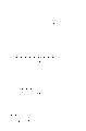
图1是示出第1实施例涉及的元件形成用衬底的制造工序的前半部分的剖面图。FIG. 1 is a cross-sectional view showing the first half of the manufacturing process of the element formation substrate according to the first embodiment.
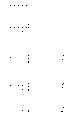
图2是示出第1实施例涉及的元件形成用衬底的制造工序的后半部分的剖面图。2 is a cross-sectional view showing the second half of the manufacturing process of the element formation substrate according to the first embodiment.
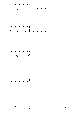
图3是示出第2实施例涉及的元件形成用衬底的制造工序的剖面图。3 is a cross-sectional view showing the manufacturing steps of the element formation substrate according to the second embodiment.
图4是示出第3实施例涉及的元件形成用衬底的制造工序的剖面图。4 is a cross-sectional view showing the manufacturing process of the element formation substrate according to the third embodiment.
图5是示出第4实施例涉及的元件形成用衬底的制造工序的剖面图。5 is a cross-sectional view showing the manufacturing steps of the element formation substrate according to the fourth embodiment.
图6是示出第5实施例涉及的元件形成用衬底的结构的剖面图。6 is a cross-sectional view showing the structure of a substrate for forming an element according to a fifth embodiment.
图7是示出各实施例中的氧化膜耐压特性和结漏泄特性的图。FIG. 7 is a graph showing oxide film withstand voltage characteristics and junction leakage characteristics in each example.
图8是示出使用第1实施例的元件形成用衬底制作的半导体装置的结构的剖面图。8 is a cross-sectional view showing the structure of a semiconductor device produced using the element formation substrate of the first embodiment.
符号说明Symbol Description
110 支撑侧衬底(第1单晶半导体衬底)110 Support side substrate (first single crystal semiconductor substrate)
111 热氧化膜(第1氧化膜)111 Thermal oxide film (first oxide film)
120 有源层侧衬底(第2单晶半导体衬底)120 Active layer side substrate (second single crystal semiconductor substrate)
121 氧化膜(第2氧化膜)121 Oxide film (second oxide film)
130 异物130 foreign body
141 氧化膜141 Oxide film
142 氮化硅膜142 Silicon nitride film
143 抗蚀剂掩模143 Resist mask
145 氮化硅膜(侧壁保护膜)145 Silicon nitride film (side wall protection film)
146 非晶质Si层146 Amorphous Si layer
147 单晶Si层147 Single crystal Si layer
148 多晶Si层148 Polycrystalline Si layer
149 热氧化膜149 thermal oxide film
150 凹陷150 Depression
具体实施方式Detailed ways
以下,利用图示的实施例说明本发明的细节。Hereinafter, details of the present invention will be described using illustrated embodiments.
(第1实施例)(first embodiment)
图1是示出本发明的第1实施例涉及的元件形成用衬底的制造工序的前半部分的剖面图。FIG. 1 is a cross-sectional view showing the first half of the manufacturing process of the element formation substrate according to the first embodiment of the present invention.
首先,如图1(a)中所示,在由单晶硅晶片构成的支撑侧衬底(第1半导体衬底)110的表面上例如利用热氧化法形成厚度为0.1μm或其以下的氧化膜(SiO2)111。同样,在由单晶硅晶片构成的有源层侧衬底(第2半导体衬底)120的表面上例如利用热氧化法形成厚度为0.1μm或其以下的氧化膜(SiO2)121。再有,图中的130表示在衬底接合时在接合界面上附着的微小的异物(尘埃)。First, as shown in FIG. 1(a), on the surface of a support side substrate (first semiconductor substrate) 110 made of a single crystal silicon wafer, for example, a thermal oxidation method is used to form an oxide film with a thickness of 0.1 μm or less. Film (SiO2 ) 111 . Similarly, an oxide film (SiO2 ) 121 having a thickness of 0.1 μm or less is formed on the surface of an active layer side substrate (second semiconductor substrate) 120 made of a silicon single crystal wafer, for example, by thermal oxidation. In the figure, 130 in the figure indicates minute foreign matter (dust) adhering to the bonding interface when the substrates are bonded.
其次,如图1(b)中所示,通过使衬底110、120的主面相互间密接,在室温下接合氧化膜111、121相互间。此时,虽然在贴合界面上不会夹入构成氧化膜111、121的氧化硅以外的物质那样进行贴合,但有时会无意地混入异物130。其后,在约1100℃下进行强化衬底间的接合用的接合热处理。接着,利用研磨或刻蚀法进行有源层侧衬底120的薄膜化。由此,有源层侧衬底120成为SOI层,氧化膜111、121成为BOX层。Next, as shown in FIG. 1(b), the
其次,如图1(c)中所示,在有源层侧衬底120上例如利用热氧化法形成厚度约为0.05μm的氧化膜(SiO2)141。在其上形成厚度约为0.2μm的氮化硅膜(SiN)142。Next, as shown in FIG. 1(c), an oxide film (SiO2 ) 141 with a thickness of about 0.05 µm is formed on the active
其次,如图1(d)中所示,在氮化硅膜142上形成抗蚀剂掩模143,使用该掩模对氮化硅膜142和氧化膜141有选择地进行刻蚀。其后,除去抗蚀剂掩模143。Next, as shown in FIG. 1(d), a resist
其次,如图1(e)中所示,使用氮化硅膜142作为掩模,除去有源层侧衬底120的一部分和氧化膜121、111的一部分。具体地说,使用氢氟酸的溶液刻蚀剂,对有源层侧衬底120进行选择刻蚀,同时进行选择刻蚀,直到包含贴合氧化膜121、111的界面的位置为止、即直到氧化膜111的中途为止。在该工序中,由于贴合界面的刻蚀率比通常的氧化膜的刻蚀率快,故在BOX层中在横方向上产生凹陷150。Next, as shown in FIG. 1(e), using the
其次,如图2(f)中所示,在有源层侧衬底120的侧面部上形成厚度约为0.1μm的侧壁绝缘膜145。具体地说,在整个面(氮化硅膜142上、氧化膜111上和氮化硅膜142、氧化膜141、有源层侧衬底120、氧化膜121、111的刻蚀侧面)上形成极薄的热氧化膜(未图示),再在其上形成氮化硅膜145。其后,通过用RIE(反应性离子刻蚀)对整个面进行刻蚀,只在有源层侧衬底120的侧壁部上留下氮化硅膜145。利用该工序,将在前面的工序中作成的BOX层中的凹陷150的内表面也用氮化硅膜145覆盖。Next, as shown in FIG. 2(f), a side
其次,如图2(g)中所示,除去有源层侧衬底120的正下方以外留下的氧化膜111。在该埋入氧化物层的除去中,使用一般使用的氢氟酸类的溶液刻蚀法。由于在该工序中露出的支撑侧衬底110的表面不是贴合界面,故即使是在例如有源层侧衬底120与支撑侧衬底110的贴合时在贴合界面上无意地混入了异物130的情况,这些混入物也不会残留,成为清洁的表面。因而,可在以后的工序中在支撑侧衬底110的露出面上形成优质的单晶硅层。此外,因为用湿法刻蚀法除去氧化膜111,故在支撑侧衬底110的表面上也不会产生因刻蚀导致的损伤。Next, as shown in FIG. 2(g), the
其次,如图2(h)中所示,在整个面上形成非晶质硅层146。具体地说,为了除去支撑侧衬底110的表面的自然氧化膜,在氢气氛下进行1000℃、400Pa、3分钟的氢清洁处理,其后,在图2(g)中示出的结构的晶片上供给SiH4气体,在500℃的温度下在晶片上均匀地形成厚度约为0.3μm的非晶质硅层146。Next, as shown in FIG. 2(h), an
其次,如图2(i)中所示,为了使非晶质硅层146结晶化,在600℃、25Pa的氢气氛(氢流量为10L/min)下进行结晶化退火。在该工序中,在支撑侧衬底110上非晶质硅层146成为单晶硅层147,在氮化硅膜142上非晶质硅层146成为多晶硅层148。Next, as shown in FIG. 2( i ), in order to crystallize the
在此,在上述的图2(g)的工序中,在未露出清洁的支撑衬底表面的情况下,结晶化不正常地进行,在支撑衬底表面上不能形成优质的单晶硅层。在本实施例中,由于露出了清洁的支撑衬底表面,故结晶化正常地进行。而且,由于在支撑侧衬底110上以单一的籽晶进行结晶化,故可制作优质的单晶硅层。Here, in the above-mentioned step of FIG. 2(g), if the clean support substrate surface is not exposed, crystallization does not proceed normally, and a high-quality single crystal silicon layer cannot be formed on the support substrate surface. In this example, since the clean support substrate surface was exposed, crystallization proceeded normally. Furthermore, since a single seed crystal is crystallized on the supporting
再有,上述的结晶化退火中的单晶化的速度约为约0.6nm/sec,如果进行500sec的处理,则通过单晶化0.3μm的厚度,可在支撑侧衬底110上与氮化硅膜142上的边界部中以多晶的状态下残留硅。此外,由于氧化膜111、121的凹陷150内的硅的周围被氮化硅膜145包围,敌难以进行结晶化,成为多晶的状态。In addition, the speed of single crystallization in the above-mentioned crystallization annealing is about 0.6 nm/sec. If the treatment is carried out for 500 sec, then by single crystallization with a thickness of 0.3 μm, the
其次,如图2(j)中所示,利用研磨或使用了氢氟酸和硝酸的混合溶液的刻蚀除去氮化硅膜142上的多晶硅层148。在此,由于单晶硅和多晶硅对于上述的混合溶液的刻蚀选择比足够大,故即使是溶液刻蚀,也能只除去多晶硅。接着,在除去了氮化硅膜142和氧化膜141后,在有源层侧衬底120的表面和多晶硅层147的表面上重新形成热氧化膜(SiO2)149。Next, as shown in FIG. 2(j), the
利用上述的工序,可制造同时具有SOI区域和高品质的非SOI区域的元件形成用衬底。Through the above-described steps, a substrate for element formation can be manufactured having both an SOI region and a high-quality non-SOI region.
这样,按照本实施例,在制作衬底贴合的SOI衬底时,通过在两者的衬底110、120的表面上形成氧化膜111、121,即使假定贴合时混入了异物130,也可使该异物停留在氧化膜111、121间,在支撑侧衬底110的表面上不会附着异物。因而,可使支撑侧衬底110的表面保持为清洁的状态,在图2(g)的工序中,可使支撑侧衬底110的清洁的表面露出。因此,可良好地进行其后接着进行的非晶质硅的淀积和单晶化,能以高品质形成非SOI区域。Thus, according to this embodiment, by forming
此外,通过在对衬底120和氧化膜121、111进行选择刻蚀时使用溶液刻蚀,可在氧化膜121、111的侧面上形成凹陷150。该凹陷150起到吸收部位(gettering site)的功能,即使在非SOI区域中存在金属污染,通过吸收该污染,也可抑制对在非SOI区域中形成的半导体器件的不良影响。Furthermore, by using solution etching when selectively etching the
再有,优选在衬底接合前在各自的衬底110、120的表面上形成的氧化膜111、121的膜厚分别为0.1μm或其以下,合计为0.2μm或其以下。这是因为,如果氧化膜111、121的膜比该范围厚,则不能使在SOI层上形成的器件在工作时发生的热散逸开来。即,难以抑制自加热。再者,对SOI衬底施加了压力,载流子的迁移率的性能变差。Furthermore, it is preferable that the film thicknesses of the
(第2实施例)(second embodiment)
图3是示出本发明的第2实施例涉及的元件形成用衬底的制造工序的剖面图。再有,图3中的310~349与图1和图2中的110~149相对应。3 is a cross-sectional view showing a manufacturing process of a substrate for forming an element according to a second embodiment of the present invention. Note that 310 to 349 in FIG. 3 correspond to 110 to 149 in FIGS. 1 and 2 .
本实施例与前面说明的第1实施例的不同点在于,进行埋入氧化物层的刻蚀,直到不包含贴合界面的位置为止。This embodiment differs from the first embodiment described above in that the etching of the buried oxide layer is performed up to a position not including the bonding interface.
在上述图1(d)中示出的工序后,如图3(a)中所示,以氮化硅膜342为掩模,除去有源层侧衬底320的一部分和氧化膜321的一部分。具体地说,使用氢氟酸类的溶液刻蚀剂,对有源层侧衬底320进行选择刻蚀,同时进行选择刻蚀,直到不包含贴合氧化膜321的界面的位置为止、即到氧化膜321的中途为止。After the process shown in FIG. 1(d) above, as shown in FIG. 3(a), a part of the active
其次,如图3(b)中所示,在有源层侧衬底320的侧面部上形成侧壁保护膜345。侧壁绝缘膜345是氮化硅膜,其形成方法与第1实施例相同。Next, as shown in FIG. 3( b ), a side wall
其次,如图3(c)中所示,除去有源层侧衬底320的正下方以外留下的氧化膜321、311。在该埋入氧化物层的除去中,使用一般使用的氢氟酸类的溶液刻蚀法。在该工序中,由于贴合界面的刻蚀率比通常的氧化膜的刻蚀率快,故在BOX层中在横方向上产生凹陷350。Next, as shown in FIG. 3(c), the
此外,由于在该工序中露出的支撑侧衬底310的表面不是贴合界面,故即使是在例如有源层侧衬底320与支撑侧衬底310的贴合时在贴合界面上无意地混入了异物330的情况,这些混入物也不会残留,成为清洁的表面。因而,可在以后的工序中在支撑侧衬底310的表面上形成优质的单晶硅层。此外,因为用湿法刻蚀法除去氧化膜312、311,故在支撑侧衬底310的表面上也不会产生因刻蚀导致的损伤。In addition, since the surface of the support-
其次,如图3(d)中所示,在整个面上形成非晶质硅层346。非晶质硅层346的形成方法与第1实施例相同。Next, as shown in FIG. 3( d ), an
在此之后,与第1实施例同样,进行使非晶质硅层346结晶化用的结晶化退火,接着除去氮化硅膜345膜上的硅,进而在除去了氮化硅膜345和氧化膜341后,通过重新形成热氧化膜349,可得到图3(e)中示出的结构。Thereafter, as in the first embodiment, crystallization annealing for crystallizing the
利用上述的工序,可制造同时具有SOI区域和高品质的非SOI区域的元件形成用衬底。而且,由于最终的结构只是氧化膜311、312的侧面的凹陷350内没有氮化硅膜345,其它的方面与第1实施例相同,故可得到与第1Through the above-described steps, a substrate for element formation can be manufactured having both an SOI region and a high-quality non-SOI region. Moreover, since the final structure is only that there is no
实施例同样的效果。Examples have the same effect.
(第3实施例)(third embodiment)
图4是示出本发明的第3实施例涉及的元件形成用衬底的制造工序的剖面图。再有,图4中的410~449与图1和图2中的110~149相对应。4 is a cross-sectional view showing a manufacturing process of a substrate for forming an element according to a third embodiment of the present invention. Note that 410 to 449 in FIG. 4 correspond to 110 to 149 in FIGS. 1 and 2 .
本实施例与前面说明的第1实施例的不同点在于,在上述图2(h)、(i)中示出的工序中的硅层的形成中,使用了选择外延生长法。This embodiment differs from the first embodiment described above in that a selective epitaxial growth method is used for the formation of the silicon layer in the steps shown in FIGS. 2(h) and (i) above.
在上述图2(g)中示出的工序后,如图4(a)中所示,在支撑侧衬底410的露出表面上对单晶硅层447有选择地进行外延生长。具体地说,利用采用了二氯硅烷和盐酸的选择外延生长法,不在氮化硅膜442上生长硅层,而是只在支撑侧衬底410的表面上对单晶硅层447进行外延生长。此时,在第1和第2实施例中被埋入了多晶硅层的部分成为空洞。该空洞也起到吸收部位的功能。此外,由于没有在氮化硅膜442上形成多晶硅层,故不需要多晶硅层的除去工艺。After the above-mentioned process shown in FIG. 2(g), as shown in FIG. Specifically, by the selective epitaxial growth method using dichlorosilane and hydrochloric acid, instead of growing a silicon layer on the
其次,如图4(b)中所示,在除去了有源层侧衬底420上的氮化硅膜442、445和氧化膜442后,通过重新形成热氧化膜449,可制造同时具有SOI区域和高品质的非SOI区域的元件形成用衬底。Next, as shown in FIG. 4(b), after removing the
(第4实施例)(fourth embodiment)
图5是示出本发明的第4实施例涉及的元件形成用衬底的制造工序的剖面图。再有,图5中的510~549与图1和图2中的110~149相对应。5 is a cross-sectional view showing a manufacturing process of a substrate for forming an element according to a fourth embodiment of the present invention. Note that 510 to 549 in FIG. 5 correspond to 110 to 149 in FIGS. 1 and 2 .
本实施例与前面说明的第1实施例的不同点在于,在更高的温度下进行衬底接合用的接合热处理。This embodiment differs from the first embodiment described above in that the bonding heat treatment for substrate bonding is performed at a higher temperature.
在上述图1(b)中示出的工序中,不是在1100℃下,而是在约1200℃的更高的温度下进行接合热处理。由此,氧化膜511、521的接合强度变大,可抑制在贴合界面上的刻蚀率的高速化。In the process shown in FIG. 1(b) above, the bonding heat treatment is performed not at 1100°C but at a higher temperature of about 1200°C. Thereby, the bonding strength of the oxide films 511 and 521 increases, and an increase in the etching rate at the bonding interface can be suppressed.
其后,与第1实施例同样,形成热氧化膜541、氮化硅膜542、抗蚀剂掩模543,有选择地除去氮化硅膜542和热氧化膜541。其后除去抗蚀剂掩模543。Thereafter, as in the first embodiment, a thermal oxide film 541, a silicon nitride film 542, and a resist mask 543 are formed, and the silicon nitride film 542 and thermal oxide film 541 are selectively removed. Thereafter, the resist mask 543 is removed.
其次,如图5(a)中所示,以氮化硅膜542为掩模,除去有源层侧衬底520的一部分和氧化膜521、511的一部分。具体地说,使用氢氟酸类的溶液刻蚀剂,对有源层侧衬底520进行选择刻蚀,同时进行选择刻蚀,直到包含贴合氧化膜521、511的界面的位置为止、即到氧化膜511的中途为止。在该工序中,因为贴合界面上的氧化膜相互间的结合退火温度比第1实施例高了约100℃,故在BOX层中在横方向上不产生凹陷。Next, as shown in FIG. 5(a), a part of the active layer side substrate 520 and parts of the oxide films 521, 511 are removed using the silicon nitride film 542 as a mask. Specifically, the substrate 520 on the active layer side is selectively etched using a solution etchant of hydrofluoric acid, and at the same time, selective etching is performed up to the position including the interface where the bonded oxide films 521 and 511 are bonded, that is, up to the middle of the oxide film 511. In this step, since the bonding annealing temperature of the oxide films on the bonding interface is about 100°C higher than that of the first embodiment, no depressions are generated in the lateral direction in the BOX layer.
在此之后,与第1实施例同样,如图5(b)中所示,在有源层侧衬底520的侧面部上形成了由氮化硅构成的侧壁绝缘膜545后,如图5(c)中所示,除去氧化膜511的剩下的部分。After that, as in the first embodiment, as shown in FIG. 5(c), the remaining portion of the oxide film 511 is removed.
其次,如图5(d)中所示,只在支撑侧衬底510的表面上形成单晶硅层547。该单晶硅层547的形成方法与第1实施例相同,在整个面上形成了非晶质硅层后进行非晶质硅层的结晶化,进而可通过利用研磨或使用了氢氟酸和硝酸的混合溶液的刻蚀除去氮化硅膜542上的硅来进行。Next, as shown in FIG. 5(d), a single-crystal silicon layer 547 is formed only on the surface of the support-side substrate 510. The method of forming this single crystal silicon layer 547 is the same as that of the first embodiment. After the amorphous silicon layer is formed on the entire surface, the amorphous silicon layer is crystallized. Etching with a mixed solution of nitric acid is performed to remove silicon on the silicon nitride film 542 .
其次,如图5(e)中所示,在除去了有源层侧衬底520上的氮化硅膜542、545和氧化膜542后,通过重新形成热氧化膜549,可制造同时具有SOI区域和高品质的非SOI区域的元件形成用衬底。Next, as shown in FIG. 5(e), after removing the silicon nitride films 542, 545 and the oxide film 542 on the substrate 520 on the active layer side, by re-forming the thermal oxide film 549, it is possible to manufacture an SOI region and high-quality non-SOI region element formation substrates.
(第5实施例)(fifth embodiment)
图6是示出本发明的第5实施例涉及的元件形成用衬底的制造工序的剖面图。再有,图6中的610~649与图1和图2中的110~149相对应。6 is a cross-sectional view showing the manufacturing process of the element formation substrate according to the fifth embodiment of the present invention. Note that 610 to 649 in FIG. 6 correspond to 110 to 149 in FIGS. 1 and 2 .
本实施例与前面说明的第1实施例的不同点在于,在衬底接合时,在氧化膜611、621间夹有多晶硅层650。This embodiment differs from the first embodiment described above in that the polysilicon layer 650 is interposed between the oxide films 611 and 621 during substrate bonding.
在第1实施例中的图1(a)的工序中,在有源层侧衬底620和支撑侧衬底610这两者的衬底表面上例如利用热氧化法形成厚度为0.1μm或其以下的氧化膜611、621。然后,在至少一方的氧化膜上形成多晶硅膜650。In the process of FIG. 1(a) in the first embodiment, on the substrate surfaces of the active layer side substrate 620 and the support side substrate 610, for example, a layer with a thickness of 0.1 μm or more is formed by thermal oxidation. The following oxide films 611, 621. Then, a polysilicon film 650 is formed on at least one of the oxide films.
其后,通过使衬底610、620的主面相互间密接,在室温下接合氧化膜611、621的一方与多晶硅膜650。其后,在约1100℃下进行强化衬底间的接合用的接合热处理。之后的工序与第1实施例完全相同。Thereafter, one of the oxide films 611 and 621 and the polysilicon film 650 are bonded at room temperature by bringing the main surfaces of the substrates 610 and 620 into close contact with each other. Thereafter, a bonding heat treatment for strengthening the bonding between the substrates is performed at about 1100°C. Subsequent steps are exactly the same as those of the first embodiment.
即使是这样的方法,由于仅仅在氧化膜611、621间存在多晶硅膜650,因此也能得到与第1实施例大致相同的效果。Even with such a method, since the polysilicon film 650 is only present between the oxide films 611 and 621, substantially the same effect as that of the first embodiment can be obtained.
其次,说明上述的各实施例中的元件形成用衬底的有意性。在第1~第5实施例中制作的部分SOI晶片的非SOI区域中制作氧化膜耐压评价用TEG,在图7(a)中示出进行了耐压评价的结果。在此,所谓「耐压C+模式」,其意义与「真性耐压」相同,是由氧化膜自身的质量决定的耐压。即,不是由于外因性的性能恶化、而是由于内因的缘故导致氧化膜自身损坏。Next, the significance of the element-forming substrates in each of the above-described embodiments will be described. In the non-SOI region of some of the SOI wafers fabricated in Examples 1 to 5, a TEG for breakdown voltage evaluation of the oxide film was produced, and the results of the withstand voltage assessment are shown in FIG. 7( a ). Here, the so-called "withstand voltage C+ mode" has the same meaning as "true withstand voltage", which is the withstand voltage determined by the quality of the oxide film itself. That is, the oxide film itself is damaged not due to exogenous performance deterioration but due to internal causes.
此外,在8英寸的晶片面内制作约9000个pn结,在图7(b)中示出评价了施加反偏压时的结漏泄特性的结果。在所谓「高漏泄」的某个偏置下,显示出比标准的漏泄电流大了二个数量级或其以上的漏泄电流的情况。In addition, about 9000 pn junctions were formed in an 8-inch wafer plane, and the results of evaluating the junction leakage characteristics when a reverse bias voltage was applied are shown in FIG. 7( b ). Under a certain bias of the so-called "high leakage", a leakage current larger than the standard leakage current by two orders of magnitude or more is shown.
如果与现有例比较,则在任一个实施例中,本部分SOI晶片的耐压都比现有的部分SOI晶片的耐压高,此外,流过大的结漏泄电流的芯片较少。这一点可认为是由于本实施例的部分SOI晶片的非SOI区域的结晶缺陷少、此外成为漏泄电流的发生源的金属杂质少的缘故。于是,通过使用本实施例的部分SOI晶片,可制作比以往品质高的半导体元件。Compared with the conventional examples, in any of the examples, the breakdown voltage of the partial SOI wafer is higher than that of the conventional partial SOI wafer, and there are fewer chips through which a large junction leakage current flows. This is considered to be due to the fact that the non-SOI region of the partial SOI wafer of the present example has few crystal defects and also has few metal impurities that cause leakage current. Therefore, by using a part of the SOI wafer of this embodiment, it is possible to fabricate a semiconductor element of higher quality than conventional ones.
在图8中示出在利用第1实施例制作的部分SOI晶片上形成了半导体元件的例子。在由经氧化膜811、821接合到支撑侧衬底810上的有源层侧衬底820构成的SOI区域上设置了逻辑元件,在支撑侧衬底810上形成了单晶硅层847的非SOI区域上设置了DRAM。FIG. 8 shows an example in which semiconductor elements are formed on a part of the SOI wafer fabricated by the first embodiment. Logic elements are placed on the SOI region consisting of the active layer substrate 820 bonded to the support substrate 810 via the oxide films 811 and 821, and the non-conductive single crystal silicon layer 847 is formed on the support substrate 810. DRAM is provided on the SOI area.
再有,图中的830表示异物,845表示氮化硅膜,861、871表示栅电极,862、872表示栅氧化膜,863、873表示源、漏扩散层,864、874表示元件隔离用绝缘膜,875表示成为存储节点的电容器电极,876表示连接源、漏与电容器电极用的扩散层,877表示将电容器电极与衬底进行绝缘隔离用的氮化膜,878表示电容器绝缘膜,879表示成为电容器的共同电极的扩散层。In addition, 830 in the figure represents a foreign matter, 845 represents a silicon nitride film, 861 and 871 represent gate electrodes, 862 and 872 represent gate oxide films, 863 and 873 represent source and drain diffusion layers, and 864 and 874 represent insulating elements for element isolation. Film, 875 represents the capacitor electrode to be the storage node, 876 represents the diffusion layer for connecting the source, drain and capacitor electrode, 877 represents the nitride film for insulating the capacitor electrode from the substrate, 878 represents the capacitor insulating film, 879 represents Diffusion layer that becomes the common electrode of the capacitor.
这样,通过在SOI区域上设置逻辑元件,可谋求逻辑元件的高性能化,通过在非SOI区域上设置DRAM,可减少伴随电路工作的漏泄电流或阈值等的特性变动。即,可同时在最佳的区域中形成逻辑元件和DRAM,可实现在同一半导体芯片上集成了逻辑元件和DRAM的高性能的LSI。In this way, by disposing logic elements in the SOI region, it is possible to improve the performance of logic elements, and by disposing DRAMs in the non-SOI region, it is possible to reduce characteristic fluctuations such as leakage current and threshold value accompanying circuit operation. That is, logic elements and DRAMs can be formed simultaneously in optimum regions, and a high-performance LSI in which logic elements and DRAMs are integrated on the same semiconductor chip can be realized.
再有,本发明不限定于上述的各实施例。部分地除去有源层侧衬底用的刻蚀深度不限于到支撑侧衬底表面的氧化膜的中途或有源层侧衬底表面的氧化膜的中途,也可刻蚀到这些氧化膜的界面。此外,适当地将在支撑侧衬底的表面上形成的氧化膜的厚度、在有源层侧衬底的表面上形成的氧化膜的厚度分别确定在0.1μm或其以下、合计0.2μm或其以下的范围内。再者,在支撑侧衬底上的单晶硅层的形成时,在实施例中在形成了非晶质硅层后进行了单晶化,但也可在形成了多晶硅层后进行单晶化。In addition, the present invention is not limited to each of the above-mentioned embodiments. The etching depth for partially removing the active layer side substrate is not limited to the middle of the oxide film on the support side substrate surface or the middle of the oxide film on the active layer side substrate surface, and may be etched to the middle of these oxide films. interface. In addition, the thickness of the oxide film formed on the surface of the substrate on the support side and the thickness of the oxide film formed on the surface of the substrate on the active layer side are suitably determined to be 0.1 μm or less, or 0.2 μm or less in total. within the following range. In addition, in the formation of the single crystal silicon layer on the support side substrate, in the embodiment, the single crystallization is performed after the amorphous silicon layer is formed, but the single crystallization may be performed after the polycrystalline silicon layer is formed. .
此外,在本实施例中,使用了硅作为第1和第2单晶半导体衬底,但也可使用硅以外的半导体作为这些衬底材料。除此以外,在不脱离本发明的要旨的范围内,可作各种变形来实施。In addition, in this embodiment, silicon is used as the first and second single crystal semiconductor substrates, but semiconductors other than silicon may be used as these substrate materials. In addition, various modifications can be made without departing from the gist of the present invention.
Claims (19)
Translated fromChineseApplications Claiming Priority (2)
| Application Number | Priority Date | Filing Date | Title |
|---|---|---|---|
| JP012197/2003 | 2003-01-21 | ||
| JP2003012197AJP3944087B2 (en) | 2003-01-21 | 2003-01-21 | Method for manufacturing element forming substrate |
Related Child Applications (1)
| Application Number | Title | Priority Date | Filing Date |
|---|---|---|---|
| CN2006100003255ADivisionCN1819215B (en) | 2003-01-21 | 2004-01-17 | Substrate for element formation, manufacturing method thereof, and semiconductor device |
Publications (2)
| Publication Number | Publication Date |
|---|---|
| CN1518058Atrue CN1518058A (en) | 2004-08-04 |
| CN1265448C CN1265448C (en) | 2006-07-19 |
Family
ID=32767322
Family Applications (2)
| Application Number | Title | Priority Date | Filing Date |
|---|---|---|---|
| CNB2004100009962AExpired - Fee RelatedCN1265448C (en) | 2003-01-21 | 2004-01-17 | Substrate for element formation, manufacturing method thereof, and semiconductor device |
| CN2006100003255AExpired - Fee RelatedCN1819215B (en) | 2003-01-21 | 2004-01-17 | Substrate for element formation, manufacturing method thereof, and semiconductor device |
Family Applications After (1)
| Application Number | Title | Priority Date | Filing Date |
|---|---|---|---|
| CN2006100003255AExpired - Fee RelatedCN1819215B (en) | 2003-01-21 | 2004-01-17 | Substrate for element formation, manufacturing method thereof, and semiconductor device |
Country Status (3)
| Country | Link |
|---|---|
| US (2) | US7285825B2 (en) |
| JP (1) | JP3944087B2 (en) |
| CN (2) | CN1265448C (en) |
Families Citing this family (17)
| Publication number | Priority date | Publication date | Assignee | Title |
|---|---|---|---|---|
| JP2005072084A (en)* | 2003-08-28 | 2005-03-17 | Toshiba Corp | Semiconductor device and manufacturing method thereof |
| JP3998677B2 (en)* | 2004-10-19 | 2007-10-31 | 株式会社東芝 | Manufacturing method of semiconductor wafer |
| JP4817641B2 (en)* | 2004-10-26 | 2011-11-16 | キヤノン株式会社 | Image forming apparatus |
| FR2880184B1 (en)* | 2004-12-28 | 2007-03-30 | Commissariat Energie Atomique | METHOD OF SORTING A STRUCTURE OBTAINED BY ASSEMBLING TWO PLATES |
| US20060175659A1 (en)* | 2005-02-07 | 2006-08-10 | International Business Machines Corporation | A cmos structure for body ties in ultra-thin soi (utsoi) substrates |
| DE102006062979B3 (en) | 2006-03-31 | 2019-03-28 | Advanced Micro Devices, Inc. | Semiconductor device with SOI transistors and solid-state transistors and a method for manufacturing |
| WO2007126907A1 (en)* | 2006-03-31 | 2007-11-08 | Advanced Micro Devices, Inc. | Semiconductor device comprising soi transistors and bulk transistors and a method of forming the same |
| DE102006015076B4 (en)* | 2006-03-31 | 2014-03-20 | Advanced Micro Devices, Inc. | Semiconductor device with SOI transistors and solid-state transistors and a method for manufacturing |
| KR100741856B1 (en)* | 2006-04-24 | 2007-07-24 | 삼성전자주식회사 | Method for Forming Soy Substrate and Soy Substrate Formed thereby |
| JP2007329200A (en)* | 2006-06-06 | 2007-12-20 | Toshiba Corp | Manufacturing method of semiconductor device |
| US7772048B2 (en)* | 2007-02-23 | 2010-08-10 | Freescale Semiconductor, Inc. | Forming semiconductor fins using a sacrificial fin |
| JP2009099598A (en)* | 2007-10-12 | 2009-05-07 | Toshiba Corp | Semiconductor device and manufacturing method thereof |
| KR101588852B1 (en)* | 2008-10-31 | 2016-01-26 | 삼성전자주식회사 | Semiconductor device and method of the same |
| DE102011087681A1 (en)* | 2011-12-02 | 2013-06-27 | Ihp Gmbh - Innovations For High Performance Microelectronics / Leibniz-Institut Für Innovative Mikroelektronik | Hetero-substrate for the production of integrated circuits with optical, opto-electronic and electronic components |
| JP5933289B2 (en) | 2012-02-23 | 2016-06-08 | 三菱電機株式会社 | SOI wafer and manufacturing method thereof |
| US9446938B2 (en)* | 2013-05-09 | 2016-09-20 | Denso Corporation | SOI substrate, physical quantity sensor, SOI substrate manufacturing method, and physical quantity sensor manufacturing method |
| US10109638B1 (en)* | 2017-10-23 | 2018-10-23 | Globalfoundries Singapore Pte. Ltd. | Embedded non-volatile memory (NVM) on fully depleted silicon-on-insulator (FD-SOI) substrate |
Family Cites Families (25)
| Publication number | Priority date | Publication date | Assignee | Title |
|---|---|---|---|---|
| JPS6412543U (en) | 1987-07-09 | 1989-01-23 | ||
| US5194395A (en)* | 1988-07-28 | 1993-03-16 | Fujitsu Limited | Method of producing a substrate having semiconductor-on-insulator structure with gettering sites |
| US4908328A (en)* | 1989-06-06 | 1990-03-13 | National Semiconductor Corporation | High voltage power IC process |
| JPH0512973A (en) | 1991-07-04 | 1993-01-22 | Omron Corp | Relay terminal |
| JPH05129173A (en) | 1991-11-01 | 1993-05-25 | Sharp Corp | Semiconductor substrate and its manufacture |
| JP2955459B2 (en)* | 1993-12-20 | 1999-10-04 | 株式会社東芝 | Method for manufacturing semiconductor device |
| US5399507A (en) | 1994-06-27 | 1995-03-21 | Motorola, Inc. | Fabrication of mixed thin-film and bulk semiconductor substrate for integrated circuit applications |
| JP3553196B2 (en) | 1995-03-29 | 2004-08-11 | コマツ電子金属株式会社 | Method for manufacturing SOI substrate |
| JPH0964321A (en) | 1995-08-24 | 1997-03-07 | Komatsu Electron Metals Co Ltd | Manufacture of soi substrate |
| US5894152A (en)* | 1997-06-18 | 1999-04-13 | International Business Machines Corporation | SOI/bulk hybrid substrate and method of forming the same |
| US5882987A (en)* | 1997-08-26 | 1999-03-16 | International Business Machines Corporation | Smart-cut process for the production of thin semiconductor material films |
| JP4313874B2 (en)* | 1999-02-02 | 2009-08-12 | キヤノン株式会社 | Substrate manufacturing method |
| US6180486B1 (en)* | 1999-02-16 | 2001-01-30 | International Business Machines Corporation | Process of fabricating planar and densely patterned silicon-on-insulator structure |
| JP2002110948A (en) | 2000-09-27 | 2002-04-12 | Toshiba Corp | Method for manufacturing semiconductor device |
| US6555891B1 (en)* | 2000-10-17 | 2003-04-29 | International Business Machines Corporation | SOI hybrid structure with selective epitaxial growth of silicon |
| JP2002184960A (en)* | 2000-12-18 | 2002-06-28 | Shin Etsu Handotai Co Ltd | SOI wafer manufacturing method and SOI wafer |
| JP2002270685A (en)* | 2001-03-08 | 2002-09-20 | Mitsubishi Electric Corp | Method for manufacturing semiconductor device |
| JP2003007856A (en)* | 2001-06-26 | 2003-01-10 | Toshiba Corp | Semiconductor device and manufacturing method thereof |
| JP2003031779A (en)* | 2001-07-13 | 2003-01-31 | Mitsubishi Electric Corp | SOI wafer manufacturing method |
| JP3984014B2 (en)* | 2001-09-26 | 2007-09-26 | 株式会社東芝 | Method for manufacturing substrate for semiconductor device and substrate for semiconductor device |
| JP4322453B2 (en)* | 2001-09-27 | 2009-09-02 | 株式会社東芝 | Semiconductor device and manufacturing method thereof |
| US6630714B2 (en)* | 2001-12-27 | 2003-10-07 | Kabushiki Kaisha Toshiba | Semiconductor device formed in semiconductor layer arranged on substrate with one of insulating film and cavity interposed between the substrate and the semiconductor layer |
| JP3943932B2 (en)* | 2001-12-27 | 2007-07-11 | 株式会社東芝 | Manufacturing method of semiconductor device |
| JP2003203967A (en)* | 2001-12-28 | 2003-07-18 | Toshiba Corp | Method for manufacturing partial SOI wafer, semiconductor device, and method for manufacturing the same |
| JP2003243528A (en)* | 2002-02-13 | 2003-08-29 | Toshiba Corp | Semiconductor device |
- 2003
- 2003-01-21JPJP2003012197Apatent/JP3944087B2/ennot_activeExpired - Fee Related
- 2003-04-07USUS10/407,677patent/US7285825B2/ennot_activeExpired - Fee Related
- 2004
- 2004-01-17CNCNB2004100009962Apatent/CN1265448C/ennot_activeExpired - Fee Related
- 2004-01-17CNCN2006100003255Apatent/CN1819215B/ennot_activeExpired - Fee Related
- 2007
- 2007-10-11USUS11/907,354patent/US7510945B2/ennot_activeExpired - Fee Related
Also Published As
| Publication number | Publication date |
|---|---|
| US7510945B2 (en) | 2009-03-31 |
| CN1265448C (en) | 2006-07-19 |
| US20040150044A1 (en) | 2004-08-05 |
| JP3944087B2 (en) | 2007-07-11 |
| CN1819215A (en) | 2006-08-16 |
| JP2004228206A (en) | 2004-08-12 |
| CN1819215B (en) | 2010-06-09 |
| US20080044983A1 (en) | 2008-02-21 |
| US7285825B2 (en) | 2007-10-23 |
Similar Documents
| Publication | Publication Date | Title |
|---|---|---|
| US7510945B2 (en) | Element formation substrate, method of manufacturing the same, and semiconductor device | |
| CN100342539C (en) | Semiconductor device and mfg. method thereof | |
| US7605022B2 (en) | Methods of manufacturing a three-dimensional semiconductor device and semiconductor devices fabricated thereby | |
| CN1230890C (en) | Method for manufacturing chip, semiconductor device using the chip and its making method | |
| CN1236494C (en) | Semiconductor device | |
| CN100454521C (en) | Semiconductor device and its manufacturing method | |
| CN100346472C (en) | Structure and method of forming semiconductor on insulating layer with multiple thicknesses | |
| CN1941375A (en) | Semiconductor device and method of making semiconductor devices | |
| CN1246906C (en) | Semiconductor device used partial SOI substrate and its manufacturing method | |
| CN1314120C (en) | Semiconductor substrate, manufacturing method therefor, and semiconductor device | |
| CN1531014A (en) | Semiconductor substrate and manufacturing method thereof, semiconductor device and manufacturing method thereof | |
| CN1645627A (en) | Integrated circuit element, transistor element and microelectronic element and manufacturing method thereof | |
| JP5511173B2 (en) | Method for manufacturing semiconductor device | |
| KR100596093B1 (en) | Manufacturing method of SOH wafer | |
| CN1905127A (en) | Method for manufacturing a semiconductor substrate and method for manufacturing a semiconductor device | |
| CN100539024C (en) | Method for forming semiconductor device | |
| CN110391173A (en) | Method for manufacturing silicon-on-insulator substrate and semiconductor device | |
| CN1828943A (en) | Semiconductor device and method for manufacturing semiconductor device | |
| US7541258B2 (en) | Method of manufacturing semiconductor substrate and method of manufacturing semiconductor device | |
| JP2001320033A (en) | Semiconductor member manufacturing method, semiconductor member using the same, and semiconductor device | |
| CN1638126A (en) | Semiconductor device and manufacturing method thereof | |
| JP4660489B2 (en) | Element forming substrate | |
| CN1770406A (en) | Manufacturing method of semiconductor device | |
| CN1588642A (en) | Three dimension complementary metal oxide semiconductor transistor structure and it spreparing method | |
| CN2726110Y (en) | Structure with semiconductor on insulating layer with multiple thicknesses |
Legal Events
| Date | Code | Title | Description |
|---|---|---|---|
| C06 | Publication | ||
| PB01 | Publication | ||
| C10 | Entry into substantive examination | ||
| SE01 | Entry into force of request for substantive examination | ||
| C14 | Grant of patent or utility model | ||
| GR01 | Patent grant | ||
| C17 | Cessation of patent right | ||
| CF01 | Termination of patent right due to non-payment of annual fee | Granted publication date:20060719 Termination date:20110117 |