CN1509979A - Drainage system - Google Patents
Drainage systemDownload PDFInfo
- Publication number
- CN1509979A CN1509979ACNA2003101223390ACN200310122339ACN1509979ACN 1509979 ACN1509979 ACN 1509979ACN A2003101223390 ACNA2003101223390 ACN A2003101223390ACN 200310122339 ACN200310122339 ACN 200310122339ACN 1509979 ACN1509979 ACN 1509979A
- Authority
- CN
- China
- Prior art keywords
- suction
- liquid
- suction nozzle
- manifold
- container
- Prior art date
- Legal status (The legal status is an assumption and is not a legal conclusion. Google has not performed a legal analysis and makes no representation as to the accuracy of the status listed.)
- Granted
Links
Images


Classifications
- G—PHYSICS
- G01—MEASURING; TESTING
- G01N—INVESTIGATING OR ANALYSING MATERIALS BY DETERMINING THEIR CHEMICAL OR PHYSICAL PROPERTIES
- G01N35/00—Automatic analysis not limited to methods or materials provided for in any single one of groups G01N1/00 - G01N33/00; Handling materials therefor
- G01N35/10—Devices for transferring samples or any liquids to, in, or from, the analysis apparatus, e.g. suction devices, injection devices
- G—PHYSICS
- G01—MEASURING; TESTING
- G01N—INVESTIGATING OR ANALYSING MATERIALS BY DETERMINING THEIR CHEMICAL OR PHYSICAL PROPERTIES
- G01N35/00—Automatic analysis not limited to methods or materials provided for in any single one of groups G01N1/00 - G01N33/00; Handling materials therefor
- G01N35/0098—Automatic analysis not limited to methods or materials provided for in any single one of groups G01N1/00 - G01N33/00; Handling materials therefor involving analyte bound to insoluble magnetic carrier, e.g. using magnetic separation
- G—PHYSICS
- G01—MEASURING; TESTING
- G01N—INVESTIGATING OR ANALYSING MATERIALS BY DETERMINING THEIR CHEMICAL OR PHYSICAL PROPERTIES
- G01N35/00—Automatic analysis not limited to methods or materials provided for in any single one of groups G01N1/00 - G01N33/00; Handling materials therefor
- G01N35/02—Automatic analysis not limited to methods or materials provided for in any single one of groups G01N1/00 - G01N33/00; Handling materials therefor using a plurality of sample containers moved by a conveyor system past one or more treatment or analysis stations
- G01N35/028—Automatic analysis not limited to methods or materials provided for in any single one of groups G01N1/00 - G01N33/00; Handling materials therefor using a plurality of sample containers moved by a conveyor system past one or more treatment or analysis stations having reaction cells in the form of microtitration plates
- G—PHYSICS
- G01—MEASURING; TESTING
- G01N—INVESTIGATING OR ANALYSING MATERIALS BY DETERMINING THEIR CHEMICAL OR PHYSICAL PROPERTIES
- G01N35/00—Automatic analysis not limited to methods or materials provided for in any single one of groups G01N1/00 - G01N33/00; Handling materials therefor
- G01N35/10—Devices for transferring samples or any liquids to, in, or from, the analysis apparatus, e.g. suction devices, injection devices
- G01N35/1065—Multiple transfer devices
- G01N35/1074—Multiple transfer devices arranged in a two-dimensional array
Landscapes
- Physics & Mathematics (AREA)
- Health & Medical Sciences (AREA)
- Life Sciences & Earth Sciences (AREA)
- Chemical & Material Sciences (AREA)
- Analytical Chemistry (AREA)
- Biochemistry (AREA)
- General Health & Medical Sciences (AREA)
- General Physics & Mathematics (AREA)
- Immunology (AREA)
- Pathology (AREA)
- Automatic Analysis And Handling Materials Therefor (AREA)
- Feeding, Discharge, Calcimining, Fusing, And Gas-Generation Devices (AREA)
Abstract
Translated fromChinese
Description
Translated fromChinese技术领域technical field
本发明涉及一种排液系统,该系统用于利用容器完成试剂添加,液体抽吸,液体排出,及分离等预定过程中所需的处理。The invention relates to a liquid drainage system, which is used to complete the required treatment in predetermined processes such as reagent addition, liquid suction, liquid discharge, and separation by using a container.
背景技术Background technique
在临床化学,生化学,制药化学等包括化学分析的领域内,反应过程中要完成各种各样的处理,如试剂的添加,液体的抽吸,排出及分离等。例如,在微型板组件或小瓶子等容器内的液体试样中含有目标物质的情况下,在液体试样中加入用于将目标物质保持在它们各自的表面上的磁性粒子。目标物质保持在磁性粒子的表面上后,上层清液被吸出和排放出,由此能够将目标物质与液体试样分离。In the fields of clinical chemistry, biochemistry, pharmaceutical chemistry, etc. including chemical analysis, various processes such as addition of reagents, suction, discharge, and separation of liquids are performed during the reaction process. For example, in the case where a target substance is contained in a liquid sample contained in a container such as a microplate assembly or a vial, magnetic particles for holding the target substance on their respective surfaces are added to the liquid sample. After the target substance is held on the surface of the magnetic particle, the supernatant is sucked and discharged, whereby the target substance can be separated from the liquid sample.
在这种处理中,只有上层清液被吸出和排放出而没有排放出容纳目标物质的磁性粒子。为此使磁铁靠近容器以将磁性粒子收集在一个地点。In this treatment, only the supernatant is aspirated and discharged without discharging the magnetic particles containing the target substance. For this purpose a magnet is brought close to the container to collect the magnetic particles in one place.
诸如使用磁性粒子分离处理的传统处理是通过手动操作或通过设有多个柱塞的抽吸机构完成的。Traditional processing, such as separation processing using magnetic particles, is done manually or by a suction mechanism provided with multiple plungers.
诸如手动分离的传统处理需要麻烦的操作,如使磁铁靠近容器的操作及通过吸液管等排放上层清液的操作。在布置许多微型板,小瓶子等细小容器用于处理的情况下,处理需要花费很长的时间。Conventional processing such as manual separation requires troublesome operations such as operations of bringing a magnet close to the container and operations of discharging supernatant liquid through a pipette or the like. In the case where many minute containers such as microplates and vials are arranged for processing, the processing takes a long time.
另一方面,为了通过柱塞致动多个微型吸液管,把多柱塞抽吸机构用于自动分离的系统需要一个高精度控制每个柱塞的致动机构。因此该系统结构复杂并昂贵。On the other hand, a system using a multi-plunger suction mechanism for automatic separation requires an actuation mechanism that controls each plunger with high precision in order to actuate multiple micropipettes by the plunger. The system is therefore complex and expensive.
发明目的purpose of invention
本发明的目的在于提供一种排液系统,该系统能够利用简单的机构完成抽吸,排放,分离等处理。The object of the present invention is to provide a liquid drainage system which can perform suction, discharge, separation and other processes with a simple mechanism.
为实现上述目的,根据本发明的第一方面提供一种排液系统,该系统包括多个用于从容器内抽吸和排放溶液的吸嘴;通过管子与吸嘴连接的多歧管;用于通过其运转经由多歧管从吸嘴中同时抽吸容器内的液体的抽吸泵;及液体输送装置,该输送装置用于将液体供给到多歧管与每个吸嘴之间的管子内由此用液体将管子注满。To achieve the above object, according to the first aspect of the present invention, a drainage system is provided, which system includes a plurality of suction nozzles for sucking and discharging solution from the container; a multi-manifold connected to the suction nozzles through pipes; A suction pump for simultaneously sucking liquid in a container from suction nozzles through a manifold by its operation; and a liquid delivery device for supplying liquid to a tube between the manifold and each suction nozzle The inside thus fills the tube with liquid.
根据本发明,利用一个抽吸泵通过多个吸嘴抽吸溶液可以通过将这些吸嘴同多歧管连接实现。另外,利用液体输送装置通过将液体注满多歧管与每个吸嘴之间的管子,可以将容器内的溶液吸出并同时从吸嘴内将其排出并且不会产生只吸出空气的空吸,即使容器的任何一部分是空的。According to the invention, suction of solution through a plurality of suction nozzles by one suction pump can be achieved by connecting these suction nozzles to a manifold. In addition, by using the liquid delivery device to fill the tube between the multi-manifold and each suction nozzle with liquid, the solution in the container can be sucked out and discharged from the suction nozzle at the same time without creating a vacuum that only sucks out air. , even if any part of the container is empty.
根据溶液排放装置的例子,在抽吸泵与多歧管之间确保有合适的容量和阻力,另外在多歧管与吸管之间也确保有合适的容量。如果吸嘴和每个多歧管之间的空间容量比容器的容量大,那么,在容器内所有的溶液被吸出之前在多歧管内可以确保一个负压,由此能够维持稳定的抽吸。另外,通过在吸嘴与多歧管之间确保合适的阻力能够得到合适的抽吸速度。According to the example of the solution discharge device, an appropriate volume and resistance are secured between the suction pump and the manifold, and an appropriate volume is also secured between the manifold and the suction pipe. If the capacity of the space between the suction nozzle and each manifold is larger than the capacity of the container, a negative pressure can be ensured in the manifold before all the solution in the container is sucked out, whereby stable suction can be maintained. In addition, an appropriate suction speed can be obtained by securing an appropriate resistance between the suction nozzle and the manifold.
另外,多歧管与抽吸泵之间的容量能够吸收抽吸泵启动或停止运转时所引起的压力突然变化,由此通过吸嘴减缓抽吸的启动和停止能够防止磁性粒子被从容器内排出。通过在多歧管和抽吸泵之间确保合适的阻力也能够得到合适的抽吸速度。In addition, the capacity between the manifold and the suction pump can absorb sudden pressure changes caused by the start or stop of the suction pump, thereby slowing the start and stop of suction through the suction nozzle can prevent magnetic particles from being drawn out of the container. discharge. Proper suction speed can also be obtained by ensuring proper resistance between the manifold and the suction pump.
为了确保多歧管与抽吸泵之间的合适容量,可以在多歧管与抽吸泵之间连接具有合适容量的管子或缓冲罐。In order to ensure a proper capacity between the manifold and the suction pump, a pipe or buffer tank with a suitable capacity can be connected between the manifold and the suction pump.
附图说明Description of drawings
在下面接合附图对优选实施例的描述中能更清楚的理解本发明上述及其他目的和特征。The above and other objects and features of the present invention can be more clearly understood in the following description of preferred embodiments in conjunction with the accompanying drawings.
图1为本发明排液系统的结构轮廓图;Fig. 1 is a structural outline diagram of the drainage system of the present invention;
图2为图1所示排液系统的工作流程图;Fig. 2 is a working flow diagram of the drainage system shown in Fig. 1;
图3A至图3D为描述图1所示排液系统的吸嘴工作图;3A to 3D are diagrams illustrating the operation of the suction nozzle of the drainage system shown in FIG. 1;
图4A至图4D为图1所示排液系统磁性粒子容纳装置的运转和结构图;4A to 4D are operation and structure diagrams of the magnetic particle containment device of the drainage system shown in FIG. 1;
图5A至图5C为图1所示排液系统吸嘴移动装置例子的运转和结构图;5A to 5C are operation and structure diagrams of an example of the suction nozzle moving device of the drainage system shown in FIG. 1;
图6A至图6C为图1所示排液系统另一个吸嘴移动装置例子的运转和结构图;6A to 6C are operation and structure diagrams of another example of the nozzle moving device of the liquid drainage system shown in FIG. 1;
图7为图1所示排液系统的吸嘴末端的结构放大图;Fig. 7 is an enlarged view of the structure of the nozzle end of the drainage system shown in Fig. 1;
图8A和图8B为图1所示排液系统吸嘴的一个变形。8A and 8B are a modification of the suction nozzle of the drainage system shown in FIG. 1 .
具体实施方式Detailed ways
下面参考图1对本发明排液系统进行概要说明。Referring to FIG. 1, the liquid drainage system of the present invention will be briefly described below.
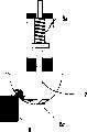
排液系统1包括多个吸嘴2,吸嘴移动装置3,磁性粒子容纳装置4,及溶液排放装置5。移动装置3将吸嘴2移向或移开诸如微型板组件的容器6。容纳装置4将磁性粒子保持在容器6内,由此防止磁性粒子被吸嘴2吸出。排放装置5使吸嘴2将溶液吸出容器6并排放到容器5f内。The liquid discharge system 1 includes a plurality of
容器6并不限于微型板组件,其可以是小瓶子等其他任何能够盛放液体试样的容器。将用于保持目标物质的磁性粒子放入容器6。在下面描述的本发明的实施例中,容器6采用的是微型板组件。The
吸嘴2的各个末端单个地插进微型板组件的井槽6a内,由此抽吸或排放液体试样等溶液。吸嘴移动装置3能够容易地将吸嘴2移向或移开微型板组件6并将吸嘴2定位在井槽6a内。The respective ends of the
吸嘴移动装置3包括用于支撑着吸嘴2移向或移开微型板组件6的支撑装置和用于推动吸嘴2移向微型板组件6的推动装置。支撑装置将吸嘴2移向微型板组件6。另外,在吸嘴端部同井槽6a接触后,推动装置将吸嘴2的各个末端单个定位在微型板组件6的井槽6a内的特定位置上并且不需要控制支撑装置的位置。The suction nozzle moving device 3 includes a supporting device for supporting the
磁性粒子容纳装置4利用磁力收集微型板组件6的井槽6a内的磁性粒子并防止它们同溶液一起被吸嘴2吸出。容纳装置4包括磁铁8和移动机构,磁铁8与微型板组件6的底侧相对放置,移动机构能够将磁铁8移向和移开微型板组件6。The magnetic particle holding device 4 uses magnetic force to collect the magnetic particles in the well groove 6a of the
溶液排放装置5通过吸嘴2同时抽吸和排放微型板组件6内的溶液。排放装置5包括具有分支端的多歧管5b,将每个分支端和吸嘴2单个相连的管子5a,用于通过多歧管从吸嘴2内抽吸溶液的抽吸泵5c,及将液体供给到管子5a以用液体将它们注满的液体输送装置(开关阀5d,输送泵5e,清洁液体容器5f,清洁液体5g等)。The solution discharge device 5 simultaneously sucks and discharges the solution in the
由于溶液排放装置5的多歧管5b同吸嘴2连接,因此液体能够被单个抽吸泵5c吸出。另外,延伸在多歧管5b和吸嘴2之间的管子5a由液体输送装置用液体注满。如果微型板组件6的任何一个井槽6a是空的,井槽6a内溶液能够自动地通过吸嘴2同时被抽吸和排放并且不会产生只有空气被吸出的空吸。Since the manifold 5b of the solution discharge device 5 is connected to the
例如,如果将多歧管5b与位于分支端的吸嘴2连接起来的管子5a的容量设置的比微型板组件6的容量大,多歧管5b到抽吸泵5c之间的部分能够保持负压,那么微型板组件6内的整个溶液能够稳定地被吸出。另外,通过使管子5a具有适当的阻力能够适当地调整抽吸的速度。For example, if the capacity of the tube 5a connecting the manifold 5b to the
在开关阀5d和抽吸泵5c之间可以设置一个缓冲罐5h作为调整从多歧管到抽吸侧部分的容量和阻力。缓冲罐5h具有特定的容量和阻力,因此如果抽吸泵运转启动或停止时产生任何突然的压力变化其易于使吸嘴2的抽吸操作柔和。如果在微型板组件6内的溶液被全部吸出之前泵停止运转,尤其是,即使是在泵停止运转后在缓冲罐5内负压作用下溶液继续被吸出,那么可以将微型板组件6撤离。这样操作时,负压随时间而降低,那么抽吸能够缓缓地结束。因此,能够防止吸出磁性粒子。A surge tank 5h may be provided between the on-off valve 5d and the suction pump 5c to adjust the capacity and resistance of the portion from the manifold to the suction side. The buffer tank 5h has a specific capacity and resistance so that it tends to soften the suction operation of the
通过布置在多歧管5b与抽吸泵5c之间的管子也可以替代缓冲罐5h来调节容量和阻力。Capacity and resistance can also be adjusted by means of pipes arranged between the manifold 5b and the suction pump 5c instead of the surge tank 5h.
下面参考流程图2对排液系统的运行进行概括的描述。A general description of the operation of the drainage system will be given below with reference to
首先,在步骤S1到步骤S3的过程中,用液体将管子5a注满。这样做即使是微型板组件6的任何井槽是空的也不会发生空吸同时还能实现吸嘴2的抽吸。First, in the course of steps S1 to S3, the tube 5a is filled with liquid. In this way, even if any well of the
吸嘴移动装置3将吸嘴2移动到与微型板组件6相距一定距离的位置上(步骤S1)。接着,转换开关阀5d使得多歧管5b同输送泵5e连通(步骤S2)。输送泵5e从清洁液体容器5f内吸出清洁液体5g,于是多歧管5b与吸嘴2之间的管子5a被清洁液体5g注满(步骤S3)。The suction nozzle moving device 3 moves the
在步骤S3的过程中,吸嘴2a和2b以及管子5a能够从中空的状态(图3A)转换到注满液体的状态(图3B)。因此,如图3B所示,通过将吸嘴2a和2b以及管子5a用液体注满,即使是微型板组件6中的一个井槽6a是空的,管子5a内的液体也能够被吸出,如图3C所示。相应地,能够防止发生只吸出空气而不吸出液体的情况。用液体将管子5a注满的操作也可用来净化吸嘴。During step S3, the suction nozzles 2a and 2b and the tube 5a can be switched from a hollow state (FIG. 3A) to a liquid-filled state (FIG. 3B). Therefore, as shown in Figure 3B, by filling the suction nozzles 2a and 2b and the tube 5a with liquid, even if a well 6a in the
图3D所示的情况为井槽6a内的液体被吸出而吸嘴2a和2b以及管子5a是空的,这种情况下,如果其中一个井槽6a是空的,那么空气就通过它被吸出。如果采用的不是高抽吸速度的泵,那么其他井槽6a内的液体就无法吸出。也许这个速度太高以至于无法防止磁性粒子同液体一起被吸出。The situation shown in Figure 3D is that the liquid in the well tank 6a is sucked out and the suction nozzles 2a and 2b and the pipe 5a are empty, in this case, if one of the well tanks 6a is empty, then the air is sucked out through it . If what adopt is not the pump of high suction speed, the liquid in other well grooves 6a just can't be sucked out so. Perhaps this velocity is too high to prevent the magnetic particles from being sucked out with the liquid.
然后,磁性粒子容纳装置4使磁铁8移向微型板组件6的底侧(步骤S4),那么磁铁8就将磁性粒子保持在微型板组件6各个井槽6a的内壁表面上(步骤S5)。Then, the magnetic particle containing device 4 moves the
下面参考图4A至4D对磁性粒子容纳装置4的一个例子进行描述。图4A至4B分别为磁性粒子容纳装置4的侧视图和主视图,其中磁铁8远离微型板组件6。4C至4D分别为磁性粒子容纳装置4的侧视图和主视图,其中磁铁8靠近微型板组件6。An example of the magnetic particle containing device 4 will be described below with reference to FIGS. 4A to 4D . 4A to 4B are side and front views, respectively, of the magnetic particle containment device 4 with the
磁性粒子容纳装置4包括第一支撑板4a和第二支撑板4e。第一支撑板4a同磁铁8配合。当基板4g上面的偏心凸轮4i转动,第二支撑板4e在4g上设置的多个支撑柱4f的导引下(在垂直方向上)移向和移开基板4g。第二支撑板4e位于第一支撑板4a的正下方,并且弹簧4c放置在第一支撑板4a与第二支撑板4e之间。如果第二支撑板4e随偏心凸轮4i转动而上升,那么该运动通过弹簧4c传递给第一支撑板4a并使得第一支撑板4a上升。凸轮4I由固定在基板4g上的电机4h驱动。凸轮4i的转动使轴承4j和支持件4k升起或降低第二支撑板4e。The magnetic particle containing device 4 includes a
轴4b的一端固定在第一支撑板4a上。另外,第二支撑板4e装备有轴保持器4d其能够容纳轴4b的末端用于滑动。弹簧4c安装在轴4b上。因此,第一支撑板4a由弹簧4c支撑在第二支撑板4e的上方。另外,轴4b和轴保持器4d也可以分别固定在第二和第一支撑板4e和4a上。One end of the shaft 4b is fixed on the
当偏心凸轮4I转动第二支撑板4e移动到其下部位置时,第一支撑板4a也移动到其下部位置,即离开微型板组件6的底面的位置。另一方面,如果偏心凸轮4I进一步转动从而将第二支撑板4e升起,那么第一支撑板4a也通过弹簧4c升起并位于靠近微型板组件6的底面的位置。这种情况下,磁铁8分别就位在微型板组件6底面上的凹槽6d内。因此,井槽6a内磁性粒子就被磁铁8吸引和收集起来。When the eccentric cam 41 rotates the
图5A至图5C所示为磁性粒子被收集在其中一个井槽6a底部6b内壁表面上的情况。5A to 5C show the case where magnetic particles are collected on the inner wall surface of the bottom 6b of one of the wells 6a.
如果在将第一和第二支撑板4a和4e之间的距离调整到支撑板4a与微型板组件6的底部6c接触之后第二支撑板4e还进一步升高,那么弹簧4c收缩以吸收第二支撑板4e的上升(图4C和图4D)。因此,由于弹簧4c收缩并且不控制第二支撑板4e或类似件的位置那么每个磁铁8能够在底部6c就位于微型板组件6相应的凹槽6d内。If the
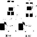
接着,吸嘴移动装置3将吸嘴2移向微型板组件5(步骤S6)。图5A至图5C和图6A至图6C给出了吸嘴移动装置3的两个例子。Next, the suction nozzle moving device 3 moves the
在图5A至图5C所示的吸嘴移动装置3 A中,吸嘴2由导引件3c可滑动地支撑并通过轴环3b由弹簧3a朝着微型板组件6推动。In the nozzle moving device 3A shown in FIGS. 5A to 5C , the
在图6A至图6C所示的吸嘴移动装置3B中,吸嘴2由导引件3c可滑动地支撑并通过轴环3b由重物3d朝着微型板组件6推动。In the nozzle moving device 3B shown in FIGS. 6A to 6C , the
在下面描述的实施例中,将把图5A至图5C所示的吸嘴移动装置3作为图1中所示的吸嘴移动装置。In the embodiments described below, the nozzle moving device 3 shown in FIGS. 5A to 5C will be used as the nozzle moving device shown in FIG. 1 .
在吸嘴移动装置移向微型板组件6时,吸嘴2的末端2A接近与其相应的微型板组件6的井槽6a并且邻近井槽6a的底部6b(步骤S7)。As the nozzle moving device moves toward the
如果吸嘴移动装置3进一步移向微型板组件6,弹簧3a吸收该额外的移动,那么吸嘴2的末端2A就能够维持与底部6b的接触。由此吸嘴2能够相对于微型板6容易地定位并且不需要对吸嘴移动装置3进行任何特别的位置控制。If the nozzle mover 3 is moved further towards the
然后,转换开关阀5使多歧管5b与抽吸泵5c或缓冲罐5h接通(步骤S8),抽吸泵5c将溶液从微型板组件6的井槽6a内吸出(步骤S9)。在抽吸过程中,预先注入管子5a的清洁液体首先被吸出,与此同时井槽6a内的溶液被抽吸进管子5a内。另外,在抽吸过程中,磁性粒子7由磁铁8收集和保持,并且由于管子5a内注满了液体,所以能够以低的抽吸速度吸出溶液。由此磁性粒子7不会被吸嘴2的抽吸排出。Then, the switch valve 5 is switched to connect the manifold 5b with the suction pump 5c or buffer tank 5h (step S8), and the suction pump 5c sucks the solution from the well groove 6a of the microplate assembly 6 (step S9). During the suction process, the cleaning liquid previously injected into the tube 5a is first sucked out, and at the same time the solution in the well 6a is sucked into the tube 5a. In addition, during the suction, the magnetic particles 7 are collected and held by the
如果微型板组件6的容量比管子5a的容量大以便在抽吸过程中将管子5a排空以通过其他的吸嘴降低抽吸的效率,那么抽吸效率的增加可以在上升步骤S1到步骤S3中通过用液体重复地将管子5a注满实现。If the capacity of the
在抽吸结束后,通过吸嘴移动装置3将每个吸嘴2同微型板组件6分离(步骤S10)。这样吸嘴2可以通过弹簧3a的推力返回并通过轴环3b就位在其初始位置上。After the suction is finished, each
转换开关阀5d使多歧管5b同输送泵5e连通(步骤S11),并通过泵5e将清洁液体容器5f内的清洁液体5g注入管子5a和吸嘴2,由此净化管子5a和吸嘴2(步骤S12)。The switch valve 5d is switched to connect the manifold 5b with the transfer pump 5e (step S11), and the cleaning liquid 5g in the cleaning liquid container 5f is injected into the pipe 5a and the
图7所示为图1中所示吸嘴2的一个例子,其中吸嘴2具有一个倾斜的末端2A。吸嘴2末端2A的斜坡能够防止末端2A的开口关闭,即使是末端2A接触到其相应井槽6a的底部。FIG. 7 shows an example of the
图8A和图8B所示为多个吸嘴2,吸嘴移动装置3分别同它们连接。如果吸嘴2的各个末端相对于微型板组件6的位置(高度)不相等,那么根据这样布置,吸嘴移动装置3的支撑装置和推进装置能够满意地使吸嘴的端部同井槽6a接触并且不需要任何特别的位置控制。8A and 8B show a plurality of
如果图1中的输送泵5e为常量输送泵,那么通过吸嘴2能够以固定的速率注射试剂。即使是以图8A所示的方式布置多个吸嘴2,通过分别调整多歧管5b和管子5a的阻力也能够以所希望的速率分送试剂。If the delivery pump 5e in FIG. 1 is a constant delivery pump, the reagent can be injected at a fixed rate through the
根据本发明的实施例,使用吸嘴移动装置,磁性粒子容纳装置,溶液排放装置,或它们的接合能够容易地实现吸液和排液并且不需要对定位进行特别的控制。According to an embodiment of the present invention, liquid suction and discharge can be easily achieved using a nozzle moving device, a magnetic particle containing device, a solution discharging device, or a combination thereof without special control of positioning.
另外,溶液能够同时通过多个吸嘴抽吸和排放,与此同时还能够清洁这些吸嘴。In addition, solutions can be aspirated and discharged through multiple nozzles at the same time, while cleaning the nozzles at the same time.
如上所述,根据本发明的排液系统,抽吸,排放和分离等过程可以利用简单的机构完成。As described above, according to the liquid discharge system of the present invention, the processes of suction, discharge and separation can be performed with a simple mechanism.
Claims (1)
Applications Claiming Priority (2)
| Application Number | Priority Date | Filing Date | Title |
|---|---|---|---|
| JP2000187928AJP2002001092A (en) | 2000-06-22 | 2000-06-22 | Drainage device |
| JP2000187928 | 2000-06-22 |
Related Parent Applications (1)
| Application Number | Title | Priority Date | Filing Date |
|---|---|---|---|
| CNB011156279ADivisionCN1160573C (en) | 2000-06-22 | 2001-04-28 | Liquid discharge system |
Publications (2)
| Publication Number | Publication Date |
|---|---|
| CN1509979Atrue CN1509979A (en) | 2004-07-07 |
| CN1255684C CN1255684C (en) | 2006-05-10 |
Family
ID=18687807
Family Applications (3)
| Application Number | Title | Priority Date | Filing Date |
|---|---|---|---|
| CN03178679.0AExpired - Fee RelatedCN1226629C (en) | 2000-06-22 | 2001-04-28 | Drainage system |
| CN200310122339.0AExpired - Fee RelatedCN1255684C (en) | 2000-06-22 | 2001-04-28 | Fluid discharge systems |
| CNB011156279AExpired - Fee RelatedCN1160573C (en) | 2000-06-22 | 2001-04-28 | Liquid discharge system |
Family Applications Before (1)
| Application Number | Title | Priority Date | Filing Date |
|---|---|---|---|
| CN03178679.0AExpired - Fee RelatedCN1226629C (en) | 2000-06-22 | 2001-04-28 | Drainage system |
Family Applications After (1)
| Application Number | Title | Priority Date | Filing Date |
|---|---|---|---|
| CNB011156279AExpired - Fee RelatedCN1160573C (en) | 2000-06-22 | 2001-04-28 | Liquid discharge system |
Country Status (4)
| Country | Link |
|---|---|
| US (1) | US7267800B2 (en) |
| JP (1) | JP2002001092A (en) |
| CN (3) | CN1226629C (en) |
| DE (1) | DE10120291A1 (en) |
Cited By (1)
| Publication number | Priority date | Publication date | Assignee | Title |
|---|---|---|---|---|
| CN110873660A (en)* | 2018-08-31 | 2020-03-10 | 深圳市帝迈生物技术有限公司 | A magnetic separation device, magnetic separation method and sample analysis device |
Families Citing this family (51)
| Publication number | Priority date | Publication date | Assignee | Title |
|---|---|---|---|---|
| US7285422B1 (en)* | 1997-01-23 | 2007-10-23 | Sequenom, Inc. | Systems and methods for preparing and analyzing low volume analyte array elements |
| US6405609B1 (en)* | 1998-02-27 | 2002-06-18 | Ventana Medical Systems, Inc. | System and method of aspirating and dispensing reagent |
| US6627157B1 (en)* | 1999-03-04 | 2003-09-30 | Ut-Battelle, Llc | Dual manifold system and method for fluid transfer |
| JP2003528299A (en)* | 1999-12-24 | 2003-09-24 | アファンティウム・インターナショナル・ベスローテン・フェンノートシャップ | Liquid distribution device |
| CN1193234C (en)* | 2000-06-30 | 2005-03-16 | 株式会社日立制作所 | Liquid dispensing method and device |
| US7135146B2 (en) | 2000-10-11 | 2006-11-14 | Innovadyne Technologies, Inc. | Universal non-contact dispense peripheral apparatus and method for a primary liquid handling device |
| US6852291B1 (en)* | 2000-10-11 | 2005-02-08 | Innovadyne Technologies, Inc. | Hybrid valve apparatus and method for fluid handling |
| EP1332000B1 (en) | 2000-10-30 | 2012-06-20 | Sequenom, Inc. | Method for delivery of submicroliter volumes onto a substrate |
| JP2004535572A (en)* | 2001-06-13 | 2004-11-25 | ケニス エフ. ウーヘンハイマー, | Automated fluid handling systems and methods |
| WO2003000422A1 (en)* | 2001-06-20 | 2003-01-03 | Cytonome, Inc. | Microfabricated two-pin liquid sample dispensing system |
| US7270785B1 (en) | 2001-11-02 | 2007-09-18 | Ventana Medical Systems, Inc. | Automated molecular pathology apparatus having fixed slide platforms |
| US7169616B2 (en) | 2002-01-25 | 2007-01-30 | Innovadyne Technologies, Inc. | Method of purging trapped gas from a system fluid contained in an actuation valve |
| DK1494808T3 (en) | 2002-04-15 | 2013-09-23 | Ventana Med Syst Inc | High capacity automated slide staining system |
| US7468161B2 (en) | 2002-04-15 | 2008-12-23 | Ventana Medical Systems, Inc. | Automated high volume slide processing system |
| US11249095B2 (en) | 2002-04-15 | 2022-02-15 | Ventana Medical Systems, Inc. | Automated high volume slide processing system |
| DK2420814T3 (en) | 2002-04-26 | 2015-10-05 | Ventana Med Syst Inc | Automatic slide processing apparatus |
| JP2004325398A (en)* | 2003-04-28 | 2004-11-18 | Hitachi Software Eng Co Ltd | Needle for continuous suction, and continuous suction device |
| US20060051247A1 (en)* | 2004-08-04 | 2006-03-09 | Irm, Llc | Multi-well container processing systems, system components, and related methods |
| US7998751B2 (en)* | 2005-04-26 | 2011-08-16 | Siemens Healthcare Diagnostics Inc. | Method and apparatus for aspirating and dispensing small liquid samples in an automated clinical analyzer |
| US7534081B2 (en)* | 2005-05-24 | 2009-05-19 | Festo Corporation | Apparatus and method for transferring samples from a source to a target |
| US7597520B2 (en)* | 2005-05-24 | 2009-10-06 | Festo Corporation | Apparatus and method for transferring samples from a source to a target |
| CN100578228C (en)* | 2005-09-09 | 2010-01-06 | 博奥生物有限公司 | A micro-liquid precision dispensing instrument and its application method |
| CN101416064B (en)* | 2006-03-28 | 2012-08-22 | 环球生物研究株式会社 | Micro plate treating device and micro plate treating method |
| US7799281B2 (en)* | 2007-01-16 | 2010-09-21 | Festo Corporation | Flux concentrator for biomagnetic particle transfer device |
| WO2008096776A1 (en)* | 2007-02-07 | 2008-08-14 | Universal Bio Research Co., Ltd. | Magnetic particle parallel processing apparatus permitting repeated use of container and method of magnetic particle parallel processing permitting repeated use of container |
| JP5094222B2 (en)* | 2007-06-15 | 2012-12-12 | シスメックス株式会社 | Sample analysis apparatus and sample analysis method |
| US20090180931A1 (en) | 2007-09-17 | 2009-07-16 | Sequenom, Inc. | Integrated robotic sample transfer device |
| JP5274124B2 (en)* | 2008-07-02 | 2013-08-28 | ベックマン コールター, インコーポレイテッド | Dispensing device |
| CA2639837C (en)* | 2008-09-29 | 2015-12-01 | Peter Lea | Method and device to remove fluid and vapor |
| CA2742473C (en) | 2008-11-12 | 2015-02-24 | Ventana Medical Systems, Inc. | Methods and apparatuses for heating slides carrying specimens |
| KR101718344B1 (en) | 2009-10-16 | 2017-03-21 | 프로메가 코포레이션 | Heating, shaking, and magnetizing apparatus and method of operating the same |
| JP5514582B2 (en)* | 2010-02-24 | 2014-06-04 | 株式会社日立製作所 | Liquid suction device |
| EP2565260B1 (en)* | 2010-04-30 | 2020-12-23 | Bioneer Corporation | Automatic biological sample purification device having a magnetic-field-applying unit, a method for extracting a target substance from a biological sample, and a protein expression and purification method |
| DE102010022552B4 (en)* | 2010-06-02 | 2013-06-27 | Perkinelmer Chemagen Technologie Gmbh | Device and method for the complete absorption of liquids from vessels |
| JP5552623B2 (en)* | 2010-12-28 | 2014-07-16 | 独立行政法人産業技術総合研究所 | Dispensing device |
| WO2013009654A1 (en) | 2011-07-08 | 2013-01-17 | Life Technologies Corporation | Method and apparatus for automated sample manipulation |
| JP5868148B2 (en)* | 2011-12-01 | 2016-02-24 | 株式会社日立製作所 | Cleaning device |
| US10682720B2 (en)* | 2012-09-07 | 2020-06-16 | Illinois Tool Works Inc. | Welding systems and devices having a configurable personal computer user interface |
| US9504981B2 (en)* | 2013-05-15 | 2016-11-29 | True Health Diagnostics Llc | Methods for purifying nucleic acids and devices thereof |
| CN105793690B (en) | 2013-12-13 | 2020-01-03 | 文塔纳医疗系统公司 | Automated histological processing of biological samples and related techniques |
| US9868555B2 (en)* | 2014-04-28 | 2018-01-16 | Robert F. LiVolsi | Systems and methods for filling inoculations |
| EP3262397B1 (en)* | 2015-02-27 | 2022-06-08 | Hycor Biomedical, LLC | Apparatuses for suspending and washing the contents of a plurality of cuvettes |
| US9656267B2 (en)* | 2015-09-17 | 2017-05-23 | Nvigen, Inc. | Magnetic rack |
| JP6258567B1 (en)* | 2016-05-26 | 2018-01-10 | 株式会社Ifg | Non-contact electrical stimulation apparatus and non-contact electrical stimulation method for cells in culture medium |
| IL264751B2 (en) | 2016-10-31 | 2024-05-01 | Amgen Inc | Purification systems and methods |
| GB201704760D0 (en)* | 2017-01-05 | 2017-05-10 | Illumina Inc | Reagent nozzle sipper mixing system and method |
| US11433402B2 (en)* | 2017-07-19 | 2022-09-06 | Amgen Inc. | Magnetic assisted separation apparatuses and related methods |
| JP2019148556A (en)* | 2018-02-28 | 2019-09-05 | シスメックス株式会社 | Bf separation device, sample analysis device, and bf separation method |
| JP7239162B2 (en)* | 2019-03-06 | 2023-03-14 | メディカテック株式会社 | Aspirator and dispensing device |
| CN113181852B (en)* | 2021-05-25 | 2023-03-24 | 湖北理工学院 | Method and equipment for preparing micronized medicine by using microreactor |
| US20240253055A1 (en)* | 2023-01-31 | 2024-08-01 | Applied Biocode Inc. | Integrated Magnetic Bead Assay Processing Method and Apparatus |
Family Cites Families (33)
| Publication number | Priority date | Publication date | Assignee | Title |
|---|---|---|---|---|
| JPS63128259A (en)* | 1986-11-18 | 1988-05-31 | Yasunobu Tsukioka | Method and device for cleaning reaction bead for inspecting blood or the like |
| EP0478753B1 (en)* | 1990-04-06 | 1997-07-02 | The Perkin-Elmer Corporation | Automated molecular biology laboratory |
| CA2046813A1 (en)* | 1990-10-02 | 1992-04-03 | Ueli Stettler | Apparatus for introducing pipetting inserts through sample cup closures |
| WO1992022879A1 (en)* | 1991-06-13 | 1992-12-23 | Abbott Laboratories | Optical imaging for positioning and cell counting |
| FR2679660B1 (en)* | 1991-07-22 | 1993-11-12 | Pasteur Diagnostics | METHOD AND MAGNETIC DEVICE FOR IMMUNOLOGICAL ANALYSIS ON A SOLID PHASE. |
| US5273717A (en)* | 1992-09-30 | 1993-12-28 | Eastman Kodak Company | Self-calibrating analyzer aspirator |
| CN2139854Y (en) | 1992-11-23 | 1993-08-11 | 上海求精玻璃仪器厂 | Adjustable step continous sample adding apparatus |
| US5334353A (en)* | 1993-02-03 | 1994-08-02 | Blattner Frederick R | Micropipette device |
| US5432098A (en)* | 1994-10-31 | 1995-07-11 | Dynatech Precision Sampling Corporation | Apparatus, and process, for automatically sampling solids and semi-solids materials for analysis |
| JP3481705B2 (en)* | 1994-12-12 | 2003-12-22 | 株式会社モリテックス | Automatic solid-phase extraction device |
| CA2183638C (en)* | 1995-03-20 | 2001-03-20 | Tajima Hideji | Liquid processing method making use of pipette device and apparatus for same |
| JP3572792B2 (en)* | 1996-04-04 | 2004-10-06 | 東ソー株式会社 | Pretreatment device |
| US6024925A (en)* | 1997-01-23 | 2000-02-15 | Sequenom, Inc. | Systems and methods for preparing low volume analyte array elements |
| US5779907A (en)* | 1996-12-06 | 1998-07-14 | Systems Research Laboratories, Inc. | Magnetic microplate separator |
| US5904899A (en)* | 1997-05-15 | 1999-05-18 | Tosoh Corporation | Assaying apparatus and a vessel holder device in use with the assaying apparatus |
| US6194160B1 (en)* | 1998-03-19 | 2001-02-27 | Immunetics, Inc. | Systems and methods for rapid blot screening |
| US5853665A (en)* | 1997-09-16 | 1998-12-29 | Coulter International Corp. | Apparatus and method for monitoring vent line vacuum |
| US6269846B1 (en)* | 1998-01-13 | 2001-08-07 | Genetic Microsystems, Inc. | Depositing fluid specimens on substrates, resulting ordered arrays, techniques for deposition of arrays |
| US6241947B1 (en)* | 1998-01-27 | 2001-06-05 | Fuji Photo Film Co., Ltd. | Chemical analysis system and blood filtering unit |
| US6033911A (en)* | 1998-02-27 | 2000-03-07 | Hamilton Company | Automated assaying device |
| DE59912484D1 (en)* | 1998-07-31 | 2005-10-06 | Tecan Trading Ag Maennedorf | magnetic separator |
| DE19835833A1 (en)* | 1998-08-07 | 2000-02-17 | Max Planck Gesellschaft | Dosing head for parallel processing of a large number of fluid samples |
| US6309891B1 (en)* | 1998-09-09 | 2001-10-30 | Incyte Genomics, Inc. | Capillary printing systems |
| DE19847759A1 (en)* | 1998-10-16 | 2000-04-20 | Dade Behring Marburg Gmbh | Interchangeable vibrating pipette needle |
| US6627157B1 (en)* | 1999-03-04 | 2003-09-30 | Ut-Battelle, Llc | Dual manifold system and method for fluid transfer |
| US6270726B1 (en)* | 1999-09-30 | 2001-08-07 | Dpc Cirrus, Inc. | Tube bottom sensing for small fluid samples |
| US6240984B1 (en)* | 2000-03-08 | 2001-06-05 | Gilson, Inc. | Foot seal for liquid handler |
| US6672458B2 (en)* | 2000-05-19 | 2004-01-06 | Becton, Dickinson And Company | System and method for manipulating magnetically responsive particles fluid samples to collect DNA or RNA from a sample |
| US6824024B2 (en)* | 2000-11-17 | 2004-11-30 | Tecan Trading Ag | Device for the take-up and/or release of liquid samples |
| US6645431B2 (en)* | 2001-01-22 | 2003-11-11 | Thomas W. Astle | Apparatus for automated magnetic separation of materials in laboratory trays |
| GB2377707B (en)* | 2001-04-26 | 2004-10-20 | Thk Co Ltd | Microarraying head and microarrayer |
| JP2004535572A (en)* | 2001-06-13 | 2004-11-25 | ケニス エフ. ウーヘンハイマー, | Automated fluid handling systems and methods |
| JP3990965B2 (en)* | 2002-10-04 | 2007-10-17 | 株式会社日立ハイテクノロジーズ | Automatic analyzer |
- 2000
- 2000-06-22JPJP2000187928Apatent/JP2002001092A/enactivePending
- 2001
- 2001-04-25DEDE10120291Apatent/DE10120291A1/ennot_activeWithdrawn
- 2001-04-28CNCN03178679.0Apatent/CN1226629C/ennot_activeExpired - Fee Related
- 2001-04-28CNCN200310122339.0Apatent/CN1255684C/ennot_activeExpired - Fee Related
- 2001-04-28CNCNB011156279Apatent/CN1160573C/ennot_activeExpired - Fee Related
- 2001-06-07USUS09/875,184patent/US7267800B2/ennot_activeExpired - Fee Related
Cited By (1)
| Publication number | Priority date | Publication date | Assignee | Title |
|---|---|---|---|---|
| CN110873660A (en)* | 2018-08-31 | 2020-03-10 | 深圳市帝迈生物技术有限公司 | A magnetic separation device, magnetic separation method and sample analysis device |
Also Published As
| Publication number | Publication date |
|---|---|
| US20010055545A1 (en) | 2001-12-27 |
| CN1495431A (en) | 2004-05-12 |
| CN1160573C (en) | 2004-08-04 |
| US7267800B2 (en) | 2007-09-11 |
| CN1332376A (en) | 2002-01-23 |
| JP2002001092A (en) | 2002-01-08 |
| CN1226629C (en) | 2005-11-09 |
| CN1255684C (en) | 2006-05-10 |
| DE10120291A1 (en) | 2002-02-28 |
Similar Documents
| Publication | Publication Date | Title |
|---|---|---|
| CN1160573C (en) | Liquid discharge system | |
| US4927765A (en) | Automatic reagent dispenser | |
| US7488451B2 (en) | Systems for particle manipulation | |
| EP0140247A2 (en) | Multiple trough vessel for automated liquid handling apparatus | |
| CN108139420A (en) | Modularized liquid processing system | |
| JP2004535572A5 (en) | ||
| US5951783A (en) | Universal washing apparatus for microtiter plate and the like | |
| CN111044739A (en) | Sample introduction method and sample introduction system for sample reagent of microfluidic chip | |
| CN1501087A (en) | Microplate Liquid Handling System | |
| CN110684650A (en) | Liquid drop generation system for digital PCR detection and digital PCR detection method | |
| EP2073018A1 (en) | Liquid suction device | |
| CN1313829C (en) | Automatic pipette arrangement with cleaning arrangement | |
| KR20240017175A (en) | Methods, devices, and apparatus for cleaning samples | |
| CA2535161C (en) | Pipette for disposable tips of different size | |
| KR102788546B1 (en) | Nucleic acid extraction and transfer apparatus | |
| CN217007339U (en) | Bubble elimination system and sample analyzer | |
| KR102629738B1 (en) | Nucleic acid extractors busy with bulk | |
| CN216566342U (en) | A liquid dispensing manipulator | |
| EP1187680B1 (en) | Universal washing apparatus for microtiter plate and the like | |
| CN115627208A (en) | Microporous membrane-based single cell/single particle capturing and separating device and method | |
| JP2004534221A (en) | Liquid treatment means for cutting device | |
| CN110684828A (en) | Digital PCR chip, digital PCR detection system and detection method | |
| WO2003042705A1 (en) | Partially filling device movable to orthogonal coordinate and cylindrical coordinate | |
| US20220214252A1 (en) | Methods, devices, and apparatus for dispensing and aspirating liquids on array plates | |
| CN213160872U (en) | Liftable multichannel electric pipettor |
Legal Events
| Date | Code | Title | Description |
|---|---|---|---|
| C06 | Publication | ||
| PB01 | Publication | ||
| C10 | Entry into substantive examination | ||
| SE01 | Entry into force of request for substantive examination | ||
| C14 | Grant of patent or utility model | ||
| GR01 | Patent grant | ||
| C17 | Cessation of patent right | ||
| CF01 | Termination of patent right due to non-payment of annual fee | Granted publication date:20060510 Termination date:20100428 |