CN1463388A - Microlens sheet and projection screen - Google Patents
Microlens sheet and projection screenDownload PDFInfo
- Publication number
- CN1463388A CN1463388ACN02801972ACN02801972ACN1463388ACN 1463388 ACN1463388 ACN 1463388ACN 02801972 ACN02801972 ACN 02801972ACN 02801972 ACN02801972 ACN 02801972ACN 1463388 ACN1463388 ACN 1463388A
- Authority
- CN
- China
- Prior art keywords
- lens
- light
- micro
- projection screen
- sheet
- Prior art date
- Legal status (The legal status is an assumption and is not a legal conclusion. Google has not performed a legal analysis and makes no representation as to the accuracy of the status listed.)
- Pending
Links
Images


Classifications
- H—ELECTRICITY
- H04—ELECTRIC COMMUNICATION TECHNIQUE
- H04N—PICTORIAL COMMUNICATION, e.g. TELEVISION
- H04N5/00—Details of television systems
- H04N5/72—Modifying the appearance of television pictures by optical filters or diffusing screens
- G—PHYSICS
- G03—PHOTOGRAPHY; CINEMATOGRAPHY; ANALOGOUS TECHNIQUES USING WAVES OTHER THAN OPTICAL WAVES; ELECTROGRAPHY; HOLOGRAPHY
- G03B—APPARATUS OR ARRANGEMENTS FOR TAKING PHOTOGRAPHS OR FOR PROJECTING OR VIEWING THEM; APPARATUS OR ARRANGEMENTS EMPLOYING ANALOGOUS TECHNIQUES USING WAVES OTHER THAN OPTICAL WAVES; ACCESSORIES THEREFOR
- G03B21/00—Projectors or projection-type viewers; Accessories therefor
- G03B21/54—Accessories
- G03B21/56—Projection screens
- G03B21/60—Projection screens characterised by the nature of the surface
- G03B21/62—Translucent screens
- G03B21/625—Lenticular translucent screens
Landscapes
- Physics & Mathematics (AREA)
- General Physics & Mathematics (AREA)
- Engineering & Computer Science (AREA)
- Multimedia (AREA)
- Signal Processing (AREA)
- Overhead Projectors And Projection Screens (AREA)
- Projection Apparatus (AREA)
Abstract
Description
Translated fromChinese技术领域technical field
本发明涉及微透镜片,尤其涉及用于面向背面投影型投影TV的图象显示屏(透过型投影屏或背面型投影屏)有效的微透镜片。The present invention relates to a microlens sheet, and more particularly to a microlens sheet effective for an image display screen (transmissive projection screen or rear projection screen) facing a rear projection type projection TV.
另外,本发明涉及用于液晶投影电视/显示器等的背面投影型显示器(电视/显示器)的,使用透镜陈列片的投影屏。Also, the present invention relates to a projection screen using a lens array for use in a rear projection type display (television/display) such as a liquid crystal projection television/display.
背景技术Background technique
透过型投影屏一般是由菲涅耳透镜片和双凸透镜片的组合构成。The transmission type projection screen is generally composed of a combination of Fresnel lens sheets and lenticular lens sheets.
菲涅耳透镜片是把来自投影机的投影光(从小口径透镜发散射)根据凸透镜特性使其成为大致平行光,并出射到双凸透镜片侧。The Fresnel lens sheet converts the projected light from the projector (diffused by a small-aperture lens) into approximately parallel light according to the characteristics of the convex lens, and emits it to the side of the lenticular lens sheet.
双凸透镜片是把从菲涅耳透镜片以大致平行光入射的投影光根据在水平方向并列的圆柱形透镜组的特性扩散到水平方向,向观察者侧以显示光出射。The lenticular lens sheet diffuses the projected light incident as substantially parallel light from the Fresnel lens sheet to the horizontal direction according to the characteristics of the cylindrical lens groups arranged in the horizontal direction, and emits it as display light toward the viewer side.
另外,背面型投影屏上一般形成有光扩散层,其目的是把显示光还扩散到垂直方向,成像来自投影机的投影光,减少投影机的小口径透镜引起的叫做闪烁的图象不必要的闪光等。In addition, a light diffusion layer is generally formed on the rear projection screen, the purpose of which is to diffuse the display light to the vertical direction, image the projection light from the projector, and reduce the unnecessary flickering of the image caused by the small-diameter lens of the projector. flash etc.
光扩散层至少是形成为由双凸透镜片、菲涅耳透镜片、或起保护板作用的最外面的前面板等的任一种,形成时采用涂敷、层叠、混入等适当方法。The light-diffusing layer is formed of at least any one of a lenticular lens sheet, a Fresnel lens sheet, or the outermost front panel serving as a protective plate, and is formed by appropriate methods such as coating, lamination, and mixing.
近年来,代替三管式(R、G、B)的CRT方式的投影机,普及了液晶式投影机、TI(美国德州仪器公司)公司的注册商标“DMD(数码微镜装置)或叫做DLP(数码光投影机)的使用反射型光阀方式的单管式投影机的显示装置,需要面向这些新型装置的适合的背面型投影屏。In recent years, instead of three-tube (R, G, B) CRT projectors, liquid crystal projectors, TI (Texas Instruments) company's registered trademark "DMD (Digital Micromirror Device) or DLP" have been popularized. (Digital light projectors) Display devices using reflective light valve system single-tube projectors require suitable rear projection screens for these new types of devices.
本申请人提案了在特开平9-120101号公报、特开平8-269546号公报、特开平10-83029号公报中举例的备有双凸透镜片的背面型投影屏。这些均涉及必须具有水平方向并列的圆柱形透镜组,并且在内部某处备有具有充分的光扩散特性的光扩散层的双凸透镜片。The present applicant has proposed a rear projection screen equipped with a lenticular lens sheet as exemplified in JP-A-9-120101, JP-A-8-269546, and JP-A-10-83029. These all relate to a lenticular lens sheet that must have cylindrical lens groups aligned in the horizontal direction and has a light-diffusing layer having sufficient light-diffusing properties somewhere inside.
如上所述,根据现有双凸透镜片的显示光视角(范围)控制是,靠透镜功能只能控制水平方向,垂直方向的控制则依赖于光扩散层。As mentioned above, according to the control of display light viewing angle (range) of the existing lenticular lens sheet, the lens function can only control the horizontal direction, and the control of the vertical direction depends on the light diffusion layer.
根据透镜功能的视角控制效果是高且动态的,但根据光扩散层的视角控制效果则相对低且平缓。The viewing angle control effect according to the lens function is high and dynamic, but the viewing angle control effect according to the light diffusing layer is relatively low and gentle.
一般来说,光扩散层是通过把光扩散性微粒分散混合在树脂中来形成。不仅难以选择光扩散性微粒和所述树脂的折射率差、光扩散性微粒的粒径(及其分布)、或分散适合性、等适合的两者的组合,而且从结构上难以控制只在垂直方向的光扩散性,必然性地影响到水平方向的光扩散性。Generally, the light-diffusing layer is formed by dispersing and mixing light-diffusing fine particles in a resin. Not only is it difficult to select a suitable combination of the refractive index difference between the light-diffusing fine particles and the resin, the particle size (and its distribution) of the light-diffusing fine particles (and its distribution), or dispersion suitability, but also structurally difficult to control the The light diffusivity in the vertical direction inevitably affects the light diffusivity in the horizontal direction.
另外,为了提高光扩散性需要过剩混入光扩散性微粒,因此在导致透过光的衰减(显示亮度下降)的同时还导致成本上升。In addition, in order to improve the light diffusibility, it is necessary to mix light diffusing fine particles in excess, which leads to attenuation of transmitted light (decrease in display luminance) and increases in cost.
根据透镜功能测量水平/垂直两方向光扩散性的试验也一直在做,但在为了控制水平方向光扩散性的透镜片外,进一步追加为了控制垂直方向光扩散性的透镜片的方法是,在安装屏幕时两方向透镜的对准会困难,以及导致部件增加带来的成本上升。The test of measuring the light diffusivity in the horizontal and vertical directions according to the function of the lens has also been done, but in addition to the lens sheet for controlling the light diffusivity in the horizontal direction, the method of adding a lens sheet for controlling the light diffusivity in the vertical direction is, in When installing the screen, it will be difficult to align the lenses in two directions, and the cost will increase due to the increase of components.
特开2000-131506号公报等中提案了一种采用透镜片的方法,该透镜片的构成为,用由菲涅耳透镜片和双凸透镜片组合构成的屏幕代替双凸透镜片,在水平以外的方向也能够控制根据透镜功能的光扩散性。Japanese Patent Application Laid-Open No. 2000-131506 etc. proposes a method using a lenticular sheet. The lenticular sheet is composed of a screen composed of a Fresnel lens sheet and a lenticular lens sheet instead of a lenticular lens sheet. The direction can also control the light diffusibility according to the lens function.
上述公报中的提案为一种透镜片,它具有把光学性凹或凸的旋转对称形状的微透镜,形成以菱形排列其形状的层的微透镜部。这些提案中需要在出射面侧配置扩散片层或需要在所述微透镜陈列部内部加入扩散剂的片层。The above-mentioned publication proposes a lens sheet having a microlens portion in which optically concave or convex rotationally symmetrical microlenses are formed into a rhombus-shaped layer. In these proposals, it is necessary to arrange a diffusion sheet on the exit surface side or to add a diffusion agent inside the microlens array.
上述新型装置中,如XGA等代表,为了提供高分辨率画质,规定投影图象的面板(液晶或显微镜排列)也根据象素数的增加而高清晰化,屏幕侧也期待着圆柱形透镜组的并列间距的高清晰化。Among the above-mentioned new devices, such as XGA, etc., in order to provide high-resolution image quality, the panel (liquid crystal or microscope arrangement) that stipulates the projected image is also high-definition by increasing the number of pixels, and the cylindrical lens is also expected on the screen side. High definition of the juxtaposition of the group.
另外,随着单位透镜并列间距的高清晰化,形成于反透镜部侧的遮光图案(BM=黑矩阵)的透光部也高清晰化,要求在根据显微陈列部的聚光部明鲜形成开口部的精度。In addition, as the pitch of the unit lens becomes higher, the light-transmitting part of the light-shielding pattern (BM = black matrix) formed on the side of the mirror lens part also becomes higher-definition. Accuracy of forming openings.
黑矩阵是由,当具有精细间距(高清晰)透镜部的透镜片时,利用对形成于透镜片的反透镜面的感光性树脂层的透镜部自身的聚光特性,正确规定各个透镜部相当于非聚光部位置的,所谓自对准方式形成。When the black matrix is a lens sheet having a fine-pitch (high-definition) lens section, each lens section is precisely defined by using the light-condensing characteristics of the lens section itself on the photosensitive resin layer formed on the reverse lens surface of the lens sheet. The so-called self-alignment method is formed at the position of the non-light-concentrating part.
自对准方式有对暴光后感光性树脂层实施显影处理后形成遮光图案的湿法,以及不对暴光后的感光性树脂层实施显影处理而是着色形成遮光图案的干法。The self-alignment method includes a wet method in which a light-shielding pattern is formed after developing the exposed photosensitive resin layer, and a dry method in which the exposed photosensitive resin layer is colored to form a light-shielding pattern without developing treatment.
干法中使用根据感光/非感光情况产生有无粘接性的具有这种特性的感光性粘合剂,对应其有无粘接性来进行着色。In the dry method, a photosensitive adhesive with such characteristics that it can produce adhesiveness depending on whether it is photosensitive or non-photosensitive is used, and it is colored according to whether it is adhesive or not.
为了形成作为透过型液晶投影屏适合遮光率(根据经验,认为60%以上范围在图象对比度方面优异)的黑矩阵,根据透镜部的聚光(聚焦)位置不在感光性树脂层的出射面侧,而是在感光性树脂层的内部,根据形成图案的遮光率适当选择。In order to form a black matrix with a suitable light-shielding ratio (according to experience, the range of 60% or more is considered to be excellent in image contrast) as a transmissive liquid crystal projection screen, the light-gathering (focusing) position of the lens part is not on the exit surface of the photosensitive resin layer. On the side, but inside the photosensitive resin layer, it is appropriately selected according to the light-shielding ratio of the pattern to be formed.
透镜形状为球面时,因像差不同而焦点位置(透镜中心部和端部)也不同,所以根据自对准方式形成遮光图案时,无法明确感光性树脂层变性之处,开口部与遮光部的界限不鲜明。When the lens shape is a spherical surface, the focus position (center and end of the lens) is different due to the difference in aberration, so when forming a light-shielding pattern by the self-alignment method, it is not clear where the photosensitive resin layer is denatured, the opening and the light-shielding portion The boundaries are not clear.
尤其为了实现高对比度化而提高遮光率时,单位透镜的并列间距高清晰,而单个单位透镜越微小,微小开口部与遮光部的界限鲜明的黑矩阵越难以形成。In particular, when the light-shielding ratio is increased to achieve high contrast, the pitch of the unit lenses is high and clear, but the smaller the individual unit lenses are, the more difficult it is to form a black matrix with a clear boundary between the tiny openings and the light-shielding parts.
另外,现在市售的用于背面投影型电视等的,现有型的透过型屏幕一般是,大概在单面形成同心圆上凹凸的菲涅耳透镜片和、在一个方向配置了圆筒状圆柱形透镜的双凸透镜片和、其中的一个在单面或者分别在基材上设置扩散层的构成。In addition, conventional transmissive screens currently on the market for use in rear-projection TVs etc. generally have concentric concentric Fresnel lens sheets formed on one side and cylinders arranged in one direction. A lenticular lens sheet of a cylindrical lens and one of them is provided with a diffusion layer on a single surface or on a base material respectively.
构成这些透过屏的部件为把从投影机照射的光线首先在菲涅耳透镜片几乎以平行光射出的光学配置,然后通过把该射出光在双凸透镜片向画面的水平方向适度扩大以得到水平视角,通过用扩散剂向画面的垂直方向扩大光线以得到垂直视角。The components that make up these transmission screens are the optical configuration that the light irradiated from the projector is first emitted as parallel light on the Fresnel lens sheet, and then the emitted light is appropriately enlarged in the horizontal direction of the screen on the lenticular lens sheet to obtain Horizontal viewing angle, by using a diffuser to expand the light in the vertical direction of the screen to obtain a vertical viewing angle.
进而,通过把不使用扩散剂也能够同时得到水平视角和垂直视角的透镜片即微透镜陈列片与双凸透镜片取代配置,取消/减量扩散剂,而能得到更明亮清晰的画质的透过型屏幕也为大家所知。Furthermore, by substituting a lens sheet that can simultaneously obtain a horizontal viewing angle and a vertical viewing angle without using a diffusing agent, i.e., a microlens display sheet, and a lenticular lens sheet, the diffusing agent can be eliminated/reduced, and a transparent lens with a brighter and clearer image quality can be obtained. Over-shaped screens are also known.
另外,把双层双凸透镜层层叠成各自圆柱形透镜轴方向直行来使用,或者在一个基材层的两面各自多个排列圆柱形透镜时,设置成各自圆柱形透镜轴方向正交的方法也为大家所知。In addition, the double-convex lens layer is laminated so that the axial direction of each cylindrical lens is straight for use, or when a plurality of cylindrical lenses are arranged on both sides of a base layer, the method of setting the axial direction of each cylindrical lens to be perpendicular is also possible. known to all.
进而,在构成该双凸透镜的各个圆柱形透镜的聚光部分,或构成微透镜陈列片的各个微透镜的聚光部分设置具有开口部的遮光层,以提高屏幕的S/N比的构成也为大家所知。Furthermore, a light-shielding layer having an opening is provided at the light-condensing portion of each cylindrical lens constituting the lenticular lens, or at the light-condensing portion of each microlens constituting the microlens display sheet, to improve the S/N ratio of the screen. known to all.
另外,也有时根据这些透过屏的用途,在最外面等设置硬涂层层或防反射膜层(AR层)。In addition, depending on the application of these transmissive screens, a hard coat layer or an antireflection layer (AR layer) may be provided on the outermost surface.
现有使用双凸透镜片或微透镜陈列片的透过型屏幕中,为了进行水平方向和垂直方向的视角控制而组合双凸透镜层和扩散层,以及因微透镜陈列需要所需量以上宽的视角,所以产生扩散层带来的光吸收、或白色散射带来的画质劣化、宽扩散带来的屏幕增益下降等弊病。In conventional transmissive screens using a lenticular lens sheet or a microlens display sheet, a lenticular lens layer and a diffusion layer are combined to control the viewing angle in the horizontal and vertical directions, and the viewing angle is wider than necessary for the microlens display Therefore, there are disadvantages such as light absorption caused by the diffusion layer, image quality degradation caused by white scattering, and screen gain reduction caused by wide diffusion.
另外,也想过通过把双层的双凸层层叠成各自圆柱形透镜轴方向直行来使用,或者在一个基材层的两面各自多个排列圆柱形透镜时,设置成各自圆柱形透镜轴方向正交,以控制水平方向及垂直方向视角的方法,但构成圆柱形透镜的材料实际上成两倍,而且还需要进行两次微细的透镜加工,因此存在材料成本、加工成本上升的问题。In addition, it is also conceivable to use it by laminating two-layer biconvex layers so that the axial direction of each cylindrical lens is straight, or when arranging a plurality of cylindrical lenses on both sides of a base layer, it is arranged so that the axial direction of each cylindrical lens Orthogonal is a method to control the viewing angle in the horizontal direction and vertical direction, but the material constituting the cylindrical lens is actually doubled, and two fine lens processing is required, so there is a problem of rising material cost and processing cost.
另外,配置成在同一平面上直行两组双凸透镜的这种构造的屏幕是,因成为两组双凸透镜互相重叠的构造,所以如果改变一方双凸透镜的形状,由此另一方双凸透镜的光学特性也会变化,无法完全独立进行视角控制。因此,其视角的控制范围被限制,在实际应用中不好。In addition, the screen with such a structure that the two sets of lenticular lenses are arranged straight on the same plane has a structure in which the two sets of lenticular lenses overlap each other. Therefore, if the shape of one lenticular lens is changed, the optical characteristics of the other lenticular lens will be affected. It will also change, and it is impossible to control the viewing angle completely independently. Therefore, the control range of its viewing angle is limited, which is not good in practical applications.
进而,把微透镜陈列作为透过型屏幕使用时,需要适合于其的尺寸,如对角50英寸的大面积制作,但此时为了得到宽视角,需要大致一半元件透镜直径程度的透镜垂度(折射面的厚度),从其成型形状的深度,难以与画面大小兼备。因此,如果是小面积可以实现必要的光学性能,但从加工上问题,其大面积化变得困难。Furthermore, when the microlens array is used as a transmissive screen, it needs to be manufactured in a size suitable for it, such as a large area with a diagonal of 50 inches. However, in order to obtain a wide viewing angle at this time, a lens sag of approximately half the diameter of the element lens is required. (The thickness of the refracting surface), from the depth of its molded shape, it is difficult to have both the size of the screen. Therefore, the necessary optical performance can be achieved if the area is small, but it is difficult to increase the area due to processing problems.
发明内容Contents of the invention
本发明的目的在于,鉴于以上背景,提供根据一片透镜片的透镜功能,能够控制不仅水平方向而是在出射方向360°范围的光扩散性,不导致光扩散剂的多量使用,适合于根据与菲涅耳透镜片的组合的由两片透镜片构成的背面型投影屏的制造,适合于高清晰度画质观察的单位透镜组以高清晰间距并列的微透镜片。The object of the present invention is to, in view of the above background, provide a lens function based on one lens sheet, which can control the light diffusivity not only in the horizontal direction but also in the range of 360° in the outgoing direction, without causing a large amount of light diffusing agent to be used. Manufacture of rear projection screen composed of two lens sheets combined with Fresnel lens sheets, microlens sheets with unit lens groups juxtaposed at high-definition pitches suitable for high-definition image quality observation.
进而,本发明的目的在于提供,尤其对于作为面向根据与菲涅耳透镜片的组合的由两片透镜片构成的背面型投影屏的透镜片适合的微透镜片,单位透镜组以200μm以下的高清晰间距并列,能够把根据透镜部的显示光的出射方向(范围)控制成宽视场的微透镜片。Furthermore, the object of the present invention is to provide a microlens sheet suitable as a lens sheet facing a rear projection screen composed of two lens sheets in combination with a Fresnel lens sheet, wherein the unit lens group has a thickness of 200 μm or less. A microlens sheet with a wide field of view can be controlled by juxtaposing the high-definition pitch to control the emission direction (range) of the display light from the lens unit.
本发明的目的还在于进一步提供,在上述微透镜片的反透镜部侧形成遮光率高(75%以上)黑矩阵外,其构成为开口部/遮光部的界限鲜明且容易形成高清晰黑矩阵的微透镜片。The object of the present invention is to further provide, in addition to forming a black matrix with a high light-shielding rate (more than 75%) on the reverse lens portion side of the above-mentioned microlens sheet, it is configured so that the boundary between the opening portion/light-shielding portion is clear and it is easy to form a high-definition black matrix microlens sheet.
进而,本发明的课题为,容易且大面积地提供光吸收少,增益降低少,抑制白色散射,使用了作为屏幕充分的光学特性的微透镜的投影屏。Furthermore, an object of the present invention is to easily provide a projection screen using microlenses with sufficient optical characteristics as a screen with less light absorption, less gain drop, and suppressed white scattering over a large area.
另外,本发明的另一课题为提供使用了材料成本、加工成本等廉价的微透镜的投影屏。Another object of the present invention is to provide a projection screen using microlenses that are inexpensive in terms of material costs, processing costs, and the like.
本发明的第一形态为一种微透镜片,对于在基板的至少单面具有单位透镜以二维性大致矩阵排列构成的微透镜陈列部的微透镜片,其特征在于:所述微透镜陈列部只在基板单面形成,含有具有非球面形状曲面的单位透镜,单位透镜的排列间距为200μm以下。A first aspect of the present invention is a microlens sheet having a microlens array on at least one side of a substrate in which unit lenses are arranged in a two-dimensional substantially matrix, wherein the microlens array The part is formed on only one side of the substrate, includes unit lenses having an aspherical curved surface, and the arrangement pitch of the unit lenses is 200 μm or less.
单位透镜组以高清晰间距并列时,所述微透镜陈列部适合由放射线固化性树脂成型。When the unit lens groups are juxtaposed at a high-resolution pitch, the microlens array is suitably molded from a radiation-curable resin.
本发明形态中也可以是这样一种微透镜片,对于在基板的至少单面具有单位透镜以二维性大致矩阵排列的微透镜陈列部的微透镜片,其特征在于:所述微透镜陈列部是放射线固化性树脂的反应固化物只在基板单面聚合粘接来构成,含有具有非球面形状曲面的单位透镜,单位透镜的排列间距为100μm以下。In the form of the present invention, it may also be a microlens sheet having a microlens array portion in which unit lenses are arranged in a two-dimensional matrix on at least one side of the substrate, wherein the microlens array is characterized in that: The part is composed of a reaction cured product of radiation curable resin polymerized and bonded on only one side of the substrate, and contains unit lenses with aspherical curved surfaces, and the arrangement pitch of the unit lenses is 100 μm or less.
所述微透镜陈列部可以只由具有球面形状曲面的单位透镜构成。The microlens array may consist only of unit lenses having spherical curved surfaces.
单位透镜的排列可以是任意排列,也可以是以正方形网眼状(围棋盘网眼状)井然的矩阵排列,单位透镜间的距离相等的三角形配置,或在该三角形配置把单位透镜区域形状做成六角形的蜂窝状配置。The arrangement of the unit lenses can be any arrangement, and can also be arranged in a square mesh (go board mesh) orderly matrix, and the distance between the unit lenses is equal to the triangle configuration, or the shape of the unit lens area is made into six in the triangle configuration. Angular honeycomb configuration.
另外,也可以是在格子状排列中,构成透镜陈列部的第n列和第n+1列(n为1以上的整数)以半间距位移的配置。单位透镜区域的形状可以是矩形、三角形等形状。邻近单位透镜区域形成的三角形有正三角形的情况和不是正三角形的情况,因其不同,水平、垂直方向的光扩散特性也会不同。In addition, in the grid arrangement, the n-th column and the n+1-th column (n is an integer of 1 or more) constituting the lens array may be arranged to be shifted by a half-pitch. The shape of the unit lens area may be a rectangle, a triangle, or the like. The triangles formed adjacent to the unit lens area may or may not be regular triangles, and because of the difference, the light diffusion characteristics in the horizontal and vertical directions will also be different.
作为背面型投影屏为了提高视觉显示图象的对比度,微透镜陈列部适合为在相反侧基板表面,在相当于根据各单位透镜非聚光部之处形成遮光层的构成。As a rear type projection screen, in order to improve the contrast of visually displayed images, the microlens array part is suitable for forming a light-shielding layer on the surface of the opposite substrate at a position corresponding to the non-condensing part of each unit lens.
本发明的第二形态微透镜片的特征在于,在基板的至少单面具有单位透镜以二维性大致矩阵排列构成的微透镜陈列部,各个单位透镜直径及其排列间距为200μm以下,根据各个单位透镜的光线射出角度范围对于微透镜片主平面的法线为±30°以上,并且,把根据各个单位透镜产生的横球面像差的范围设计成对于透镜直径为0%<横球面像差≤50%。The microlens sheet according to the second aspect of the present invention is characterized in that at least one surface of the substrate has a microlens array in which unit lenses are arranged in a two-dimensional approximately matrix, and the diameter and arrangement pitch of each unit lens are 200 μm or less. The light emission angle range of the unit lens is more than ±30° to the normal line of the main plane of the microlens sheet, and the range of the lateral spherical aberration generated by each unit lens is designed to be 0%<the lateral spherical aberration for the lens diameter ≤50%.
本发明的第三形态为一种投影屏,使用在基板的至少单面具有单位透镜以二维性大致矩阵排列构成的微透镜陈列部的微透镜片的投影屏,其特征在于:单位透镜的特定方向的断面形状对于与所述方向正交方向的断面形状为小曲率,由这些连续性面构成的复曲面形成,在透光性片的单面形成将上述单位透镜以二维性大致矩阵排列构成的微透镜陈列部,在微透镜陈列部相反侧的所述片表面形成具有单位透镜组和合并光轴的开口部的遮光层。A third aspect of the present invention is a projection screen using a microlens sheet having a microlens array of unit lenses arranged in a two-dimensional approximately matrix on at least one side of a substrate, characterized in that: The cross-sectional shape in a specific direction has a small curvature relative to the cross-sectional shape in the direction perpendicular to the direction, and the toric surface composed of these continuous surfaces is formed. In the microlens array formed in an array, a light-shielding layer having a unit lens group and an opening for combining optical axes is formed on the surface of the sheet opposite to the microlens array.
本发明的第四形态为,使用第一形态微透镜片的投影屏,其特征在于:在所述透光性片的单面形成将上述单位透镜以二维性大致矩阵排列构成的微透镜陈列部时,各单位透镜排列成曲率方向一致的构成。A fourth aspect of the present invention is the projection screen using the microlens sheet of the first aspect, wherein a microlens array comprising the unit lenses described above in a two-dimensional substantially matrix arrangement is formed on one side of the translucent sheet. At the same time, each unit lens is arranged in a configuration in which the direction of curvature is consistent.
本发明的第五形态为,如权利要求1所述的投影屏,其特征在于:所述复曲面为,对于特定方向断面的曲率部厚度的,与所述方向正交方向的断面的曲率部厚度,即透镜垂度比为2/3以下的构成。A fifth aspect of the present invention is the projection screen according to
本发明的第六形态为,使用第一形态微透镜片的投影屏,其特征在于:所述复曲面为,对于水平方向断面的曲率部厚度的,垂直方向断面的曲率部厚度,即透镜垂度(lens sag)比为2/3以下的构成。The sixth aspect of the present invention is the projection screen using the microlens sheet of the first aspect, wherein the toric surface is the thickness of the curvature portion of the vertical section relative to the thickness of the curvature portion of the horizontal section, that is, the thickness of the vertical section of the lens. A composition with a lens sag ratio of 2/3 or less.
本发明的第七形态为,使用第一形态微透镜片的投影屏,其特征在于:所述微透镜陈列部在作为透过型投影屏使用时,形成于成为入射侧(投影机侧)的透光性片的单面。A seventh aspect of the present invention is the projection screen using the microlens sheet of the first aspect, wherein the microlens array part is formed on the incident side (projector side) when used as a transmissive projection screen. One side of the translucent sheet.
本发明的第八形态为,任意所述形态记载的投影屏,其特征在于:所述遮光层是在设置于透光性片的反透镜部侧表面的感光性树脂层表面,在不会根据通过微透镜陈列部的暴光而聚光的非感光区域形成,所述感光性树脂层或在其表面形成的层的折射率低于透光性片。The eighth aspect of the present invention is the projection screen described in any of the above-mentioned aspects, wherein the light-shielding layer is provided on the surface of the photosensitive resin layer provided on the surface of the translucent sheet on the side of the mirror portion, and is not exposed to The non-photosensitive region formed by the light exposure of the microlens display part is concentrated, and the refractive index of the photosensitive resin layer or the layer formed on its surface is lower than that of the light-transmitting sheet.
本发明的第九形态的特征在于:把使用第一形态微透镜片的投影屏作为透过型投影屏使用时,在入射侧(投影机侧)进一步备有在单面具有同心圆上轮带结构的菲涅耳透镜。The ninth aspect of the present invention is characterized in that: when using the projection screen using the microlens sheet of the first aspect as a transmissive projection screen, the incident side (projector side) is further equipped with a concentric circle on one side. Structured Fresnel lens.
附图说明Description of drawings
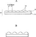
图1是本发明微透镜片一例的断面示意图。Fig. 1 is a schematic cross-sectional view of an example of the microlens sheet of the present invention.
图2是图1微透镜片的平面示意图。FIG. 2 is a schematic plan view of the microlens sheet in FIG. 1 .
图3A是单位透镜为球面形状的情况(现有技术)表示光路的断面图,图3B是表示横球面像差的图表。3A is a cross-sectional view showing an optical path when the unit lens has a spherical shape (conventional technology), and FIG. 3B is a graph showing lateral spherical aberration.
图4A是单位透镜为如本发明规定非球面形状的情况表示光路的断面图,图4B是表示横球面像差的图表。4A is a cross-sectional view showing an optical path when the unit lens has an aspherical shape as defined in the present invention, and FIG. 4B is a graph showing lateral spherical aberration.
图5是本发明中微透镜片一例的断面示意图。Fig. 5 is a schematic cross-sectional view of an example of a microlens sheet in the present invention.
图6是表示本发明中横球面像差少的单位透镜断面形状一例的曲线。Fig. 6 is a graph showing an example of a cross-sectional shape of a unit lens with less lateral spherical aberration in the present invention.
图7是单位透镜为如本发明规定非球面形状的情况,表示BM面暴光分布例的图表。Fig. 7 is a graph showing an example of light distribution on a BM surface when the unit lens has an aspherical shape as specified in the present invention.
图8A、8B是用于本发明投影屏的微透镜片元件透镜的概略图。8A, 8B are schematic diagrams of microlens sheet element lenses used in the projection screen of the present invention.
图9是构成用于本发明投影屏的微透镜陈列片的元件透镜的斜视图。Fig. 9 is a perspective view of element lenses constituting the microlens array used in the projection screen of the present invention.
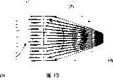
图10是构成用于本发明投影屏的微透镜陈列片的元件透镜的垂直方向断面图。Fig. 10 is a cross-sectional view in the vertical direction of element lenses constituting the microlens array sheet used in the projection screen of the present invention.
图11是构成用于本发明投影屏的微透镜陈列片的元件透镜的水平方向断面图。Fig. 11 is a cross-sectional view in the horizontal direction of element lenses constituting the microlens array used in the projection screen of the present invention.
图12是使用本发明微透镜片的背面型投影机显示装置的例子。Fig. 12 is an example of a rear projector display device using the lenticular sheet of the present invention.
图13是使用本发明微透镜片的投影机显示装置的屏幕构造示意图。FIG. 13 is a schematic diagram of the screen structure of a projector display device using the microlens sheet of the present invention.
具体实施方式 Detailed ways
在对发明实施例说明之前,在这里说明对应于单位透镜形状的聚光特性和横球面像差。Before describing the embodiments of the invention, the condensing characteristics and lateral spherical aberration corresponding to the shape of the unit lens will be described here.
图1是单位透镜为球面形状的情况表示光路的断面图(图3A)和表示横球面像差的图表(图3B)。图4A是单位透镜为如本发明规定非球面形状的情况表示光路的断面图(4A)和表示横球面像差的图表(图4B)。Fig. 1 is a cross-sectional view ( Fig. 3A ) showing an optical path and a graph ( Fig. 3B ) showing a transverse spherical aberration when the unit lens has a spherical shape. 4A is a cross-sectional view (4A) showing an optical path and a graph ( FIG. 4B ) showing lateral spherical aberration when the unit lens has an aspheric shape as prescribed in the present invention.
图3A中,从同图左侧向单位透镜10入射的平行光线入射到球面形状单位透镜表面后受到折射,聚光成在同图右侧汇聚焦点,然后在同图向上下扩散出射。In Fig. 3A, the parallel light rays incident on the
此时根据球面像差,入射到单位透镜中心部的光线焦点长(在同图位于右侧),入射到单位透镜端部的光线焦点短(在同图位于左侧)。这叫做纵球面像差。At this time, due to spherical aberration, the focal point of the light incident on the center of the unit lens is long (right in the figure), and the focal point of light incident on the edge of the unit lens is short (left in the figure). This is called longitudinal spherical aberration.
另一方面,根据球面像差,把单位透镜的中心部记为y=0作为横轴(PY),把出射光线和出射面相交位置离光轴的距离记为Δy(y=0时,Δy=0)作为纵轴(EY)制作曲线,则成为表示横球面像差的图表—图3A。On the other hand, according to the spherical aberration, the central part of the unit lens is marked as y=0 as the horizontal axis (PY), and the distance between the intersection position of the outgoing light and the outgoing surface from the optical axis is marked as Δy (when y=0, Δy =0) If a curve is drawn as the vertical axis (EY), it becomes a graph showing transverse spherical aberration—FIG. 3A.
图4A、4B为球面像差少的单位透镜形状的情况。如图4A所示,从单位透镜的中心部到端部,焦点位置大致一致(纵球面像差少)。对应于此,图4B中EY的变动小,表现出横球面像差少。4A and 4B show the case of a unit lens shape with less spherical aberration. As shown in FIG. 4A , the focal positions of the unit lens are substantially uniform from the center to the end (less longitudinal spherical aberration). Correspondingly, in FIG. 4B , the fluctuation of EY is small, showing little transverse spherical aberration.
图6为表示横球面像差少的本发明单位透镜的断面形状一例的曲线。Fig. 6 is a graph showing an example of the cross-sectional shape of the unit lens of the present invention having less lateral spherical aberration.
本发明中微透镜片的用途并不限定于透过型投影屏,还适用于反射型投影屏,或不是如透过型/反射型投影屏的大尺寸(30英寸以上)的,具备背光等内置光源的显示器中,为了把来自所述光源的照明光在显示画面内控制成均匀的亮度和/或均匀的出射方向的导光体。作用The use of the microlens sheet in the present invention is not limited to the transmissive projection screen, and is also applicable to the reflective projection screen, or is not as large-sized (30 inches or more) as the transmissive/reflective projection screen, and has a backlight, etc. In a display with a built-in light source, a light guide is used to control the illumination light from the light source to a uniform brightness and/or a uniform emission direction within the display screen. effect
根据对应于单位透镜形状的光学特性,控制显示光的出射方向(范围)时,背面型投影屏的情况下,从不依赖光扩散剂来扩展视场,不需要使用多量光扩散剂,不导致屏幕的成本上升等方面来说,优选对光轴(对于屏幕主面的法线方向)扩展。According to the optical characteristics corresponding to the shape of the unit lens, when controlling the outgoing direction (range) of the display light, in the case of the rear type projection screen, it never depends on the light diffusing agent to expand the field of view, does not need to use a large amount of light diffusing agent, and does not cause It is preferable to expand the optical axis (the direction normal to the main surface of the screen) in terms of increasing the cost of the screen.
本发明通过使各个透镜的光线出射角对于光轴为±30°以上,能够得到作为透过型屏幕必要的视角特性,进一步期待如下作用效果。BM率的上升In the present invention, by setting the light emission angle of each lens to be ±30° or more with respect to the optical axis, it is possible to obtain viewing angle characteristics necessary for a transmissive screen, and the following effects are further expected. Increase in BM rate
如上所述,可以用根据自对准方式在微透镜片上的微细透镜入射平行光线时的聚光图案形成BM,但根据具有如本发明横球面像差的微细单位透镜,能够将其开口部面积做得极其小。As mentioned above, it is possible to form BM with the condensing pattern when parallel rays are incident on the microlens on the microlens sheet according to the self-alignment method, but according to the micro unit lens with transverse spherical aberration as in the present invention, the opening area can be reduced Made extremely small.
图7为单位透镜为如本发明规定非球面形状的情况的表示BM面暴光分布例的图表,因聚光部为脉冲波状尖锐的形状,所以聚光部/非聚光部的界限明确,根据自对准方式形成BM时,容易明确基于如上所述感光性粘合剂粘接部/非粘接部的遮光层形成部/非形成部,容易形成鲜明的遮光图案。由此,能够得到具有高遮光率(75%以上)的BM,得到能容易显示高对比度图象的屏幕。Fig. 7 is a graph showing an example of the light distribution on the BM surface when the unit lens has an aspherical shape as specified in the present invention. Since the converging part has a pulse-like sharp shape, the boundary between the converging part and the non-concentrating part is clear. According to When the BM is formed by the self-alignment method, it is easy to clarify the light-shielding layer formed part/non-formed part by the above-mentioned photosensitive adhesive bonded part/non-bonded part, and it is easy to form a clear light-shielding pattern. Thereby, a BM having a high light-shielding ratio (75% or more) can be obtained, and a screen capable of easily displaying high-contrast images can be obtained.
把形成BM的表面(自对准方式的情况为感光材料表面)与透镜片基材的界限定义为“成像面)时,优选通过把横球面像差的变动范围定在单位透镜直径的50%以下,使BM面积率(遮光率)形成为75%以上,但通过进一步把横球面像差的变动范围定在透镜直径的31%以下,能够使BM面积率(遮光率)成90%以上,能够与对比度一起大幅度提高S/N。成品率的提高When defining the boundary between the surface on which the BM is formed (the surface of the photosensitive material in the case of the self-alignment method) and the lens sheet substrate as the "imaging surface), it is preferable to set the variation range of the transverse spherical aberration at 50% of the diameter of the unit lens. Hereinafter, the BM area ratio (light shielding ratio) is set to be 75% or more, but by further setting the range of variation of the lateral spherical aberration to 31% or less of the lens diameter, the BM area ratio (light shielding ratio) can be made 90% or more, S/N can be greatly improved together with the contrast ratio. Improvement of yield
根据自对准方式形成BM时,因球面像差少,所以在焦点的聚光高,因此,暴光部的照度提高,对于外界光(通过单位透镜出射的非平行光)的S/N提高。其结果,能够得到不易被干扰左右的具有正确遮光图案的透镜片。When the BM is formed by the self-alignment method, since the spherical aberration is small, the focus at the focal point is high, so the illuminance of the exposed part is improved, and the S/N of the external light (non-parallel light emitted through the unit lens) is improved. As a result, it is possible to obtain a lens sheet having an accurate light-shielding pattern that is less likely to be affected by noise.
另外,作为感光材料层,通过设置折射率比透镜片低的层,并调节其厚度,能够容易调节BM的精锐度。In addition, by providing a layer having a lower refractive index than the lens sheet as the photosensitive material layer and adjusting its thickness, the sharpness of the BM can be easily adjusted.
下面,参照附图说明本发明实施例。Hereinafter, embodiments of the present invention will be described with reference to the drawings.
实施例1:Example 1:
图12为表示液晶背面型投影机电视的概略构成的断面图。附号各自表示:31为光源灯,32为光学机构部,33为液晶板,34为第一个镜子,35为投射透镜,36为第二个镜子,37为屏幕。图13为对于屏幕37从上方看A-A断面的断面图。图13中,附号各自表示:38为菲涅耳透镜,39为微透镜,40为黑矩阵部,41为保护层,42为硬涂层部。Fig. 12 is a cross-sectional view showing a schematic configuration of a liquid crystal rear projector television. The appended numbers represent respectively: 31 is a light source lamp, 32 is an optical mechanism, 33 is a liquid crystal panel, 34 is a first mirror, 35 is a projection lens, 36 is a second mirror, and 37 is a screen. FIG. 13 is a cross-sectional view of the screen 37 viewed from above along the line A-A. In FIG. 13 , reference numerals indicate respectively: 38 is a Fresnel lens, 39 is a microlens, 40 is a black matrix part, 41 is a protective layer, and 42 is a hard coat part.
图1A、1B为表示微透镜片10的断面图。1A and 1B are cross-sectional views showing a
在基板11的一侧表面聚合粘接了由放射线固化性树脂的反应固化物构成的微透镜陈列部12,微透镜陈列部12为具有非球面形状曲面的单位透镜13以200μm以下(优选100μm以下)间距排列的构成。On one side surface of the
图1A中是邻近单位透镜13之间相连的状态,但也可以是如图1B所示邻近单位透镜13之间相离的状态。In FIG. 1A , the
如果不要求达到以100μm以下间距排列单位透镜13程度的高清晰化时,微透镜陈列部12没必要由放射线固化性树脂的反应固化物形成,可以由向热塑性树脂片表面的冲压成型等形成。If it is not required to achieve high definition by arranging the
图2A~2D为表示图1微透镜片10的平面图。2A to 2D are plan views showing the
单位透镜13是在基板11表面以200μm以下间距大致矩阵状排列,其排列方法没有限制,可以是如图2A所示井然的正方形网眼状(围棋盘网眼状)矩阵排列,也可以是如图2B、2C所示的三角形排列,也可以是如图2D所示根据六角形单位透镜的蜂窝状排列。The
同图中邻近单位透镜区域是表示单位透镜之间边相接的情况。The area adjacent to the unit lens in the same figure indicates that the sides of the unit lenses are connected.
在本发明中规定的单位透镜是,在图2A、2C中为矩形、在图2B中为三角形、在图2D中为六角形,图2A中为在单位透镜内具有用圆形表示透镜部(曲率)的构成,也可以是由矩形、三角形、六角形等形状形成的单位透镜内全体具有透镜部(曲率)的构成。邻近单位透镜在图2中是指单位透镜边相接的情况,单位透镜之间的排列间距是指单位透镜中心的相离距离。The unit lens specified in the present invention is a rectangle in FIGS. 2A and 2C, a triangle in FIG. 2B, and a hexagon in FIG. 2D. In FIG. 2A, the lens portion ( Curvature) may be a configuration in which the entire lens portion (curvature) is provided in a unit lens formed in a shape such as a rectangle, a triangle, or a hexagon. Adjacent unit lenses in FIG. 2 refer to the case where the sides of the unit lenses are connected, and the arrangement distance between the unit lenses refers to the distance between the centers of the unit lenses.
图2A(正方形)、图2B(正三角形)、图2D(正六角形)的情况,邻近单位透镜之间的排列间距为等间隔,但如图2C(长方形)的情况,第n列间的单位透镜陈列间距与第n列和第n+1列间的单位透镜陈列间距则不同。In the case of Fig. 2A (square), Fig. 2B (equal triangle), and Fig. 2D (regular hexagon), the arrangement spacing between adjacent unit lenses is equal intervals, but as in the case of Fig. 2C (rectangle), the units between the n columns The lens arrangement pitch is different from the unit lens arrangement pitch between the nth column and the n+1th column.
图2A所示排列的情况,如在图1所述,有邻近单位透镜13之间相接的情况和相离的情况。In the case of the arrangement shown in FIG. 2A , as described in FIG. 1 , there are cases where
在图2B、2C、2D所示排列中,产生单位透镜13的配置间距(假如100μm)以上精细的周期性(在图2C的例子中,由周期a与周期b组合的新的100μm间距的周期),能够进一步对减少从投影机的与投影像素的间距比引起的莫尔条纹做贡献,具有优越性。In the arrangement shown in FIGS. 2B, 2C, and 2D, a periodicity finer than the arrangement pitch (assuming 100 μm) of the unit lenses 13 (in the example of FIG. 2C, a new period of 100 μm pitch combined by period a and period b ), which can further contribute to the reduction of moiré fringes caused by the pitch ratio of the projector to the projected pixels, which is advantageous.
制作这种微透镜片10时,制作成型用冲压机后,采用冲压成型或挤压成型、或根据2P法(Photo-Polymer法,感光性聚合物法)的成型。When producing such a
上述冲压机为微透镜片10的倒型(即单位透镜部成凹部的表面形状),除了在金属层表面物理性雕刻所述凹部(或化学性腐蚀)等方法外,还使用通过激光加工雕刻所述凹部的方法。The above-mentioned punching machine is an inverted type of the microlens sheet 10 (that is, the surface shape of the unit lens portion is a concave portion). In addition to physically engraving the concave portion (or chemical corrosion) on the surface of the metal layer, it is also used to engrave the concave portion by laser processing. method of the recess.
不管是任何方法,都必须正确加工单位透镜的曲面形状,根据目的(精细度)选择方法。Regardless of the method, it is necessary to correctly process the curved shape of the unit lens, and the method is selected according to the purpose (fineness).
另外,从透镜的顶部到谷底部分的位置(从基材表面的距离)是由单位透镜的曲面形状决定。单位透镜为正方形或正六角形且旋转对称形状的透镜时,从顶部到谷底部分的长度(高度)在单位透镜的周边部将不同。In addition, the position from the top of the lens to the bottom of the valley (distance from the substrate surface) is determined by the shape of the curved surface of the unit lens. When the unit lens is a square or regular hexagonal lens having a rotationally symmetric shape, the length (height) from the top to the bottom of the valley varies around the periphery of the unit lens.
单位透镜的曲面形状可以是球面也可以是非球面,另外,为了能够把水平方向与垂直方向的扩散特性控制得不同,需要严格控制所述凹部的形状。The curved surface shape of the unit lens may be spherical or aspherical. In addition, in order to control the diffusion characteristics in the horizontal direction and the vertical direction to be different, it is necessary to strictly control the shape of the concave portion.
另外,在微透镜片10的成为反透镜部侧的基板11的平坦面形成遮光层时,优选采用通过在所述平坦面整面形成感光层(通过感光粘接性消失的已知材料)后,由微透镜陈列侧暴光,使相当于聚光部部分的感光层变性,在相当于非聚光部部分附着墨水或色剂的方法(所谓根据透镜自身的叫做自对准的公知方法),在正确位置形成遮光层(未图示)。In addition, when forming a light-shielding layer on the flat surface of the
实施例2:Example 2:
图5为表示本发明中微透镜片101的一例的断面图。FIG. 5 is a cross-sectional view showing an example of the microlens sheet 101 in the present invention.
在透明支撑体103的单面由放射线固化性树脂的固化物形成透镜部(单位透镜组)102,在透明支撑体103的相反侧的平坦面,在相当于各单位透镜非聚光部的位置,隔着正型感光性粘接层104形成具有点状开口的遮光图案(BM=黑矩阵)105的构成。On one side of the
透明支撑体103举例有聚对苯二甲酸乙二醇酯(PET)、聚碳酸酯(PC)等。Examples of the
单位透镜直径及其排列间距优选为200μm以下,以作为适合于高清晰图象的观察的屏幕。The diameter of the unit lens and its arrangement pitch are preferably 200 μm or less to serve as a screen suitable for observing high-definition images.
这种精细间距化通过由放射线固化性树脂的固化物以2P法(Photo-Polymer法,感光性聚合物法)成型透镜部而变得可能。Such finer pitches are made possible by molding the lens portion from a cured product of a radiation curable resin by a 2P method (Photo-Polymer method, photopolymer method).
图5的例子中,在折射率1.50,厚度75μm的透明支撑体3的单面,根据2P法,由放射线固化性树脂的固化物形成非球面透镜形状且单位透镜直径为80μm的透镜部。In the example of FIG. 5 , on one side of a
同图的情况,横球面像差的最大幅度为6μm(对于透镜直径为7.5%),能够以92.5%的遮光率形成BM。In the case of the same figure, the maximum width of the transverse spherical aberration is 6 μm (7.5% with respect to the lens diameter), and BM can be formed with a shading ratio of 92.5%.
即使是同一材料与尺寸,当单位透镜形状为球面时,横球面像差的最大幅度为30μm(对于透镜直径为37.5%),能够形成的BM的遮光率最大达到62.5%。Even with the same material and size, when the shape of the unit lens is spherical, the maximum amplitude of the transverse spherical aberration is 30 μm (37.5% for the lens diameter), and the shading rate of the BM that can be formed reaches a maximum of 62.5%.
通过把上述微透镜片接合一片或多片用于画面尺寸30英寸以上的背面投影机式显示装置,能够观察到对比度高,视场宽的图象。By bonding one or more of the above microlens sheets to a rear projector type display device with a screen size of 30 inches or more, images with high contrast and a wide field of view can be observed.
微透镜片的情况,与具有圆柱形透镜组的双凸透镜片相比,透镜片的接合界限不明显,大画面化时弊病少。In the case of a microlens sheet, compared with a lenticular lens sheet having a cylindrical lens group, the bonding boundary of the lens sheet is not clear, and there are fewer disadvantages when enlarging the screen.
另外,在上述情况中,如果在作为图象光源的投影机侧配置菲涅耳透镜片,则在对微透镜片入射平行光时,能够缩短投影机和屏幕之间的距离,不仅能够小型化显示装置的深度,而且能只在必要范围出射亮度高的显示图象光,因此好。In addition, in the above case, if the Fresnel lens sheet is arranged on the side of the projector as the image light source, when parallel light is incident on the microlens sheet, the distance between the projector and the screen can be shortened, and not only the size can be reduced. The depth of the display device and the ability to emit high-brightness display image light only within the necessary range are preferred.
另外,在上述情况中,也可以把分散光扩散剂构成的光扩散层配置于菲涅耳透镜片侧和/或微透镜片侧的任意位置。In addition, in the above case, the light-diffusing layer made of a dispersed light-diffusing agent may be arranged at an arbitrary position on the Fresnel lens sheet side and/or the microlens sheet side.
在这里使用的扩散剂可以使用无机系材料的硅、铝、钙、或含有它们的氧化物的无机质粉末或玻璃珠,或由有机系材料的丙烯酸系树脂、苯乙烯系树脂、聚碳酸酯系树脂、丙烯酸系/苯乙烯系共聚树脂等构成的微粒。The diffusing agent used here can use inorganic materials such as silicon, aluminum, calcium, or inorganic powder or glass beads containing their oxides, or organic materials such as acrylic resin, styrene resin, polycarbonate Microparticles composed of resins, acrylic/styrene copolymer resins, etc.
光扩散剂的选择需要考虑与粘合剂树脂的折射率差等光学性质、表面光泽、成型为光扩散基材或光扩散墨水时的分散性、成型时的脆性等后加入。平均粒径适合为5μm以上,优选5~20μm,更优选5~10μm程度。The selection of the light-diffusing agent needs to be added after considering optical properties such as the difference in refractive index with the binder resin, surface gloss, dispersibility when molded into a light-diffusion base material or light-diffusion ink, and brittleness during molding. The average particle diameter is suitably 5 μm or more, preferably 5 to 20 μm, and more preferably about 5 to 10 μm.
通过光扩散层的拼用,在控制视场时,在与正面有距离的观察方向也能够平滑降低亮度,同时根据微小的透镜陈列的凹凸(粗糙面)成像,从而提高成像图象光的作用。Through the combined use of the light diffusion layer, when controlling the field of view, the brightness can be smoothly reduced in the observation direction with a distance from the front, and at the same time, the image is formed according to the unevenness (rough surface) of the tiny lens array, thereby improving the effect of imaging image light .
单位透镜越微细,微透镜片的透镜部表面越能够起到与粗糙面同样的功能,因此对使用光扩散剂的光扩散层的依赖度降低,但只根据所述透镜部表面的成像及光扩散性不充分时,拼用所述光扩散层。The finer the unit lens is, the more the surface of the lens part of the microlens sheet can perform the same function as a rough surface, so the dependence on the light-diffusing layer using a light-diffusing agent is reduced. When the diffusivity is insufficient, the above-mentioned light-diffusing layer is combined.
另外,作为投影屏,不仅适用于背面投影型,而且通过把上述微透镜片接合一片或多片,还能适用于画面尺寸30英寸以上的正面投影机式显示装置。In addition, as a projection screen, not only a rear projection type but also a front projection type display device with a screen size of 30 inches or more can be applied by joining one or more of the above-mentioned microlens sheets.
作为反射型屏幕使用时,在微透镜片的反透镜部侧整面形成光反射层。When used as a reflective screen, a light reflective layer is formed on the entire surface of the microlens sheet on the reverse lens portion side.
进而,上述微透镜片还能适用于为了把来自光源的照明光在显示画面内控制成均匀的亮度和/或均匀的出射方向的导光体。Furthermore, the above-mentioned microlens sheet can also be applied to a light guide for controlling illumination light from a light source to have uniform luminance and/or a uniform emission direction within a display screen.
这种显示器以具有背光的液晶显示装置(监视器或携带式终端)为代表。Such displays are typified by liquid crystal display devices (monitors or portable terminals) with backlights.
实施例3:Example 3:
下面基于附图详细说明作为本发明一个实施例的投影屏的实施例。Hereinafter, an embodiment of a projection screen as an embodiment of the present invention will be described in detail based on the drawings.
图8A、8B为用于本发明投影屏的微透镜片元件透镜的概略图。图9为构成用于本发明投影屏的微透镜片的元件透镜的斜视图。图10为构成用于本发明投影屏的微透镜片的元件透镜的垂直方向断面图。图11为构成用于本发明投影屏的微透镜片的元件透镜的水平方向断面图。在这里表示的透镜陈列片为实际进行透镜形状设计,并基于此制成的形状图。8A and 8B are schematic diagrams of the lens of the microlens sheet element used in the projection screen of the present invention. Fig. 9 is a perspective view of element lenses constituting the microlens sheet used in the projection screen of the present invention. Fig. 10 is a cross-sectional view in the vertical direction of element lenses constituting the microlens sheet used in the projection screen of the present invention. Fig. 11 is a cross-sectional view in the horizontal direction of element lenses constituting the microlens sheet used in the projection screen of the present invention. The lens display sheet shown here is a shape drawing based on actual lens shape design.
图8B中透镜片的全体厚度(反透镜面的平坦面到透镜顶部的距离)相同,但对于旋转对称形状的复曲面形状的单位透镜的情况,从透镜的顶部到谷底部分的距离即使在同一单位透镜内,也在A-A’断面的D1和B-B’断面的D2会不同。The overall thickness of the lens sheet in FIG. 8B (the distance from the flat surface of the reverse lens surface to the top of the lens) is the same, but in the case of a unit lens with a toric surface shape of a rotationally symmetrical shape, even if the distance from the top of the lens to the bottom of the lens is at the same Also in the unit lens, D1 of the AA' section and D2 of the BB' section are different.
该透镜陈列片的主要特征为构成透镜陈列层的元件透镜的形状。该透镜陈列层是由板状基材层和在其上面设置的透镜层构成。The main feature of the lens display sheet is the shape of the element lenses constituting the lens display layer. The lens display layer is composed of a plate base layer and a lens layer arranged on it.
构成这些透镜陈列的元件透镜为非球面形状,并且具有对于透镜轴为非旋转对称的三维几何形状。其断面形状是根据其断面的取决不仅有球面,而且还有包括椭圆面、抛物面或高次项的所谓非球面形状。The element lenses that make up these lens arrays are aspherical in shape and have a three-dimensional geometry that is not rotationally symmetric about the lens axis. Its cross-sectional shape depends on its cross-section. There are not only spherical surfaces, but also so-called aspherical shapes including ellipsoids, paraboloids, or higher-order terms.
如果使用这种非球面与非旋转对称形状的透镜,可以利用光线射出时的折射角之差,对元件透镜几乎平行入射的入射光(3)在入射面(1)对应于其入射位置折射,其结果对于正交于光轴的平面上的正交坐标轴(对于垂直配置的屏幕则相当于垂直方向和水平方向),能够具有各不相同的光线的折射率,因此,能够得到对应于目的的配光特性(参照图10、11)。If such an aspherical and non-rotationally symmetrical lens is used, the difference in the refraction angle when the light is emitted can be used to refract the incident light (3) that is almost parallel to the element lens on the incident surface (1) corresponding to its incident position, As a result, for the orthogonal coordinate axes on the plane perpendicular to the optical axis (equivalent to the vertical direction and the horizontal direction for a vertically arranged screen), it is possible to have different refractive indices of light rays, and therefore, it is possible to obtain The light distribution characteristics (refer to Figures 10 and 11).
具体来说,如图10、11所示,射出光(4)的聚光位置表现为在厚度方向不同的现象,此时光线的射出角度即相当于配光角度特性。Specifically, as shown in FIGS. 10 and 11 , the condensing position of the emitted light ( 4 ) is different in the thickness direction, and the emitted light angle at this time corresponds to the light distribution angle characteristic.
透镜陈列层的材料可以不做限制地使用玻璃、塑料等透明材料且用于光学用部件的材料,从生产效率等方面考虑优选使用塑料。The material of the lens display layer can be transparent materials such as glass and plastic and materials used for optical components without limitation, and plastic is preferably used in terms of production efficiency and the like.
塑料原材料举例有如聚甲基丙烯酸甲酯等丙烯酸系树脂、聚碳酸酯树脂、丙烯酸-苯乙烯共聚树脂、苯乙烯系树脂、聚氯乙烯树脂等。Examples of plastic raw materials include acrylic resins such as polymethyl methacrylate, polycarbonate resins, acrylic-styrene copolymer resins, styrene resins, and polyvinyl chloride resins.
另外,因能够进行精细间距的微细加工,所以作为透镜层材料优选使用紫外线固化性树脂或电子射线固化性树脂等放射线固化性树脂。放射线固化性树脂可以使用如在聚氨酯(甲基)丙烯酸酯和/或环氧树脂(甲基)丙烯酸酯低聚物中添加反应稀释剂、光聚合引发剂、光敏剂等的组合物等。聚氨酯(甲基)丙烯酸酯低聚物并不是特别限定的物质,可以用如乙二醇、1,4-丁二醇、新戊二醇、聚己内酯聚醇、聚酯聚醇、聚碳酸酯二醇、聚对苯二甲酸乙二醇酯等聚醇类和六甲撑二异氰酸酯、异佛尔酮二异氰酸酯、甲苯撑二异氰酸酯、二甲苯二异氰酸酯等聚异氰酸酯类反应而得到。环氧树脂(甲基)丙烯酸酯低聚物并不是特别限定的物质,可以用如双酚A型环氧树脂、双酚F型环氧树脂、酚醛清漆型环氧树脂、双酚A型环氧丙烷加成物的末端缩水甘油醚、芴环氧树脂等环氧树脂类和(甲基)丙烯酸反应而得到。In addition, since fine-pitch microfabrication is possible, radiation curable resins such as ultraviolet curable resins and electron beam curable resins are preferably used as lens layer materials. As the radiation curable resin, for example, a composition in which a reactive diluent, a photopolymerization initiator, a photosensitizer, etc. are added to urethane (meth)acrylate and/or epoxy resin (meth)acrylate oligomer, etc. can be used. The urethane (meth)acrylate oligomer is not particularly limited, and for example, ethylene glycol, 1,4-butanediol, neopentyl glycol, polycaprolactone polyol, polyester polyol, poly It is obtained by reacting polyalcohols such as carbonate diol and polyethylene terephthalate with polyisocyanates such as hexamethylene diisocyanate, isophorone diisocyanate, tolylene diisocyanate, and xylene diisocyanate. Epoxy resin (meth)acrylate oligomers are not particularly limited substances, such as bisphenol A type epoxy resin, bisphenol F type epoxy resin, novolak type epoxy resin, bisphenol A type epoxy resin, It is obtained by reacting epoxy resins such as terminal glycidyl ethers of oxypropylene adducts and fluorene epoxy resins with (meth)acrylic acid.
透镜陈列层可以用以下方法制造。在由塑料构成的基材层上,以未固化状态涂敷放射线固化性树脂,在其表面压住成型用冲压机进行冲压的同时,照射给定放射线进行固化,以形成透镜层。The lens display layer can be fabricated by the following method. A radiation-curable resin is coated in an uncured state on a base material layer made of plastic, and is cured by irradiating predetermined radiation while pressing its surface against a molding press to form a lens layer.
所述成型用冲压机可以用如下方法形成透镜层。使用光刻蚀法技术的方法是,准备雕刻了元件透镜的断层形状的多个掩模,使用该掩模顺次进行暴光硅片,RIE等各向异性刻蚀,在其深度方向顺次反复雕刻,得到具有给定设计形状的成型用冲压机。The molding press machine can form a lens layer as follows. The method of using photolithography technology is to prepare a plurality of masks in which the tomographic shape of the element lens is engraved, and use the mask to sequentially perform anisotropic etching such as exposure of the silicon wafer, RIE, etc., in the depth direction. Engraving, resulting in a stamping machine for forming with a given design shape.
这样,透镜陈列片层可以用与用于现有双凸透镜制造等的方法相同的方法制造。Thus, the lens display sheet can be produced by the same method as that used for the production of conventional lenticular lenses and the like.
感光性树脂层和遮光层可以用如下方法制造。实际上与作为投影屏使用的状态相同来平行配置菲涅尔透镜,经该菲涅尔透镜从透镜陈列片的透镜层侧照射光线,则透过透镜陈列层暴光部分的感光性树脂层变性,粘接性消失。然后,对该感光性树脂层压紧具备含有碳黑等的黑色转印层的转印膜,则转印层将选择性地转移到具有粘接性的未暴光部分,形成遮光层。The photosensitive resin layer and the light-shielding layer can be manufactured as follows. In fact, the Fresnel lens is arranged in parallel in the same state as the projection screen, and the light is irradiated from the lens layer side of the lens display sheet through the Fresnel lens, and the photosensitive resin layer of the exposed part of the lens display layer is denatured, Adhesiveness disappears. Then, a transfer film provided with a black transfer layer containing carbon black or the like is pressed against the photosensitive resin layer, and the transfer layer is selectively transferred to an adhesive unexposed portion to form a light-shielding layer.
形成遮光层时,对应于由复曲面微透镜聚光光线引起的线段状的成像图案,该成像位置大概反映复曲面微透镜的非点像差,因此在光轴方向(厚度方向)产生最大两处。通过在该两处的焦点(几何光学上称为径向焦点和子午焦点)中,在形成透镜片最适合的位置插入低折射率层进行调节,并在该位置设置黑色遮光层,可以得到更高比率的BM图案。When the light-shielding layer is formed, corresponding to the segment-shaped imaging pattern caused by the light collected by the toric microlens, the imaging position roughly reflects the astigmatic aberration of the toric microlens, so the maximum two angles are generated in the optical axis direction (thickness direction). place. By inserting a low-refractive index layer at the most suitable position for forming a lens sheet among the two focal points (referred to as radial focal point and meridional focal point in geometrical optics), and adjusting a black light-shielding layer at this position, a better lens can be obtained. High ratio of BM patterns.
这里,使用低折射率层是因为,因其折射力弱而能取大的对厚度的公差,从而能够提高其加工性。Here, the low-refractive-index layer is used because it can take a large tolerance in thickness due to its weak refractive power, thereby improving its processability.
然后,通过在该遮光层上根据需要设置粘合剂层、扩散层、及硬涂层层等,制成透镜陈列片。Then, a lens display sheet is produced by providing an adhesive layer, a diffusion layer, a hard coat layer, and the like as necessary on the light-shielding layer.
这样,对于该透镜陈列片,通过适当设计一个复曲面透镜陈列的形状,对透过该透镜陈列层的光线能够控制垂直方向和水平方向两方向的配光特性(视角),尤其通过把其比率设定为2/3以下,能够实现适合于投影屏的垂直/水平配光特性的分配,能够得到作为屏幕良好的特性。In this way, for the lens display sheet, by properly designing the shape of a toric lens display, the light distribution characteristics (viewing angle) in the vertical direction and the horizontal direction can be controlled for the light passing through the lens display layer, especially by making the ratio When it is set to 2/3 or less, distribution suitable for the vertical/horizontal light distribution characteristics of the projection screen can be realized, and good characteristics can be obtained as a screen.
进而,与使用两层透镜陈列层或者在基材层两面形成透镜层的情况相比,能够更低地控制材料成本、加工成本。Furthermore, compared with the case of using two lens display layers or forming lens layers on both sides of the substrate layer, the material cost and processing cost can be lower controlled.
另外,简化扩散层,可以减少扩散层的光吸收或增益降低。其结果能够抑制扩散层引起的白色散射现象,能够实现高S/N比。In addition, the simplification of the diffusion layer can reduce light absorption or decrease in gain of the diffusion layer. As a result, the white scattering phenomenon caused by the diffusion layer can be suppressed, and a high S/N ratio can be realized.
进而,通过加菲涅尔透镜,能缩短自投影机的投射距离,通过与这些功能兼备,能够得到优异的屏幕。Furthermore, the projection distance from the projector can be shortened by the Gafresnel lens, and an excellent screen can be obtained by combining these functions.
对于本发明透镜陈列片的各层厚度、透镜层的间距等不做特别限定,可以根据用途等适当变更。实验例The thickness of each layer of the lens display sheet of the present invention, the pitch of the lens layers, etc. are not particularly limited, and can be appropriately changed according to the application and the like. Experimental example
下面根据实验例进一步具体说明本发明。The present invention will be further described in detail based on experimental examples below.
本实验例中设计参数决定如下,进行其结果的验证实验。设计参数In this experimental example, the design parameters were determined as follows, and a verification experiment of the results was performed. Design Parameters
对于透镜陈列层的基材层,其材料为聚对苯二甲酸乙二醇酯,厚度为0.075mm。对于透镜陈列层的透镜层,其材料为UV感光性树脂,透镜间间距为0.080mm,透镜垂度(透镜的山的高度)的大断面(对应于屏幕左右方向)为椭圆,透镜垂度的小断面为球面,其垂度量比为2∶1的复曲面形状。感光性树脂层使用厚度20微米的クロマリン(cromarin)膜(商品名:杜邦公司制造)。For the substrate layer of the lens display layer, its material is polyethylene terephthalate, and its thickness is 0.075 mm. For the lens layer of the lens display layer, its material is UV photosensitive resin, the distance between the lenses is 0.080mm, the large section (corresponding to the left and right direction of the screen) of the lens sag (the height of the lens mountain) is an ellipse, and the lens sag The small section is a spherical surface, and its sag ratio is a toric surface shape of 2:1. As the photosensitive resin layer, a cromarin film (trade name: manufactured by DuPont) having a thickness of 20 micrometers was used.
对该透镜陈列片的透镜形成面照射平行校正为1~5°程度的平行光进行感光层雕刻,转印厚度2微米的墨箔(碳黑转印箔)作为遮光层,得到具有对应于构成透镜陈列的微透镜的开口的遮光层。The lens forming surface of the lens display sheet is irradiated with parallel light with a parallel correction of 1 to 5° to engrave the photosensitive layer, and transfer an ink foil (carbon black transfer foil) with a thickness of 2 microns as a light-shielding layer to obtain The light-shielding layer of the openings of the microlenses of the lens array.
这样得到的透镜陈列片把透镜陈列面朝向光源侧用于水平垂直方向的光扩散,确认能够个别得到对应于透镜陈列形状的视角。The lens array sheet thus obtained was used for light diffusion in the horizontal and vertical directions with the lens array surface facing the light source side, and it was confirmed that a viewing angle corresponding to the shape of the lens array can be individually obtained.
本发明微透镜片适用于由与菲涅尔透镜片组合的两片透镜片形成的简单构成的背面型投影屏的制造,对能够不感到莫尔条纹而观察到高清晰度画质的图象非常适合。The microlens sheet of the present invention is suitable for the manufacture of a rear projection screen with a simple structure formed by two lens sheets combined with a Fresnel lens sheet, and can observe high-definition image quality without feeling moire fringes very suitable.
根据本发明微透镜片,单位透镜组以200μm以下的高清晰间距并列设置,能够把根据透镜部的显示光的出射方向(范围)控制成宽视场。According to the microlens sheet of the present invention, the unit lens groups are arranged side by side at a high-definition pitch of 200 μm or less, and the emission direction (range) of the display light by the lens portion can be controlled to a wide field of view.
尤其,根据本发明,在所述微透镜片的反透镜部侧形成遮光率高(75%以上)的黑矩阵外,能够容易地形成开口部/遮光部的界限鲜明的高清晰黑矩阵。In particular, according to the present invention, in addition to forming a black matrix with a high light shielding rate (75% or more) on the reverse lens portion side of the microlens sheet, it is possible to easily form a high-definition black matrix with a clear boundary between openings and light shielding portions.
进而,根据用于本发明投影屏的具有微透镜陈列部的微透镜片,对透过透镜陈列层的光线,通过适当变化元件透镜的复曲面形状能够控制垂直方向和水平方向两方向的配光特性(视角)。这表明能够能动性地控制屏幕的光学特性,对缩短开发期、减少费用具有大效果。Furthermore, according to the microlens sheet with the microlens display part used in the projection screen of the present invention, the light distribution in the vertical direction and the horizontal direction can be controlled by appropriately changing the toric shape of the element lens for the light passing through the lens display layer. Features (perspective). This shows that the ability to actively control the optical characteristics of the screen has a great effect on shortening the development period and reducing costs.
另外,能够用一片微透镜片就可以自如设定垂直方向和水平方向独立的视角,因此具有如下效果:1)显著降低加工成本;2)因能够根据现有手头上材料设定扩散剂的量(效果),所以不需要材料的开发/配合;3)因能够最低限度地抑制光线吸收(光量损失),所以能够得到使用微透镜片的容易明亮的投影屏。In addition, independent viewing angles in the vertical and horizontal directions can be freely set with a single microlens sheet, so it has the following effects: 1) Remarkably reduce processing costs; 2) The amount of diffusing agent can be set according to the existing materials on hand (Effect), so there is no need for material development/combination; 3) Since light absorption (light loss) can be suppressed to a minimum, it is possible to obtain a projection screen that is easy to be bright using a microlens sheet.
另外,与现有屏幕相比能减少扩散剂,所以能够抑制外界光的乱散射,透明度提高而增加遮光层的光吸收作用,从而能够得到使用了以往没有的S/N提高的微透镜片的投影屏。In addition, compared with the existing screen, the diffusion agent can be reduced, so the random scattering of external light can be suppressed, the transparency can be improved, and the light absorption effect of the light-shielding layer can be increased, so that it is possible to use a microlens sheet with an improved S/N that has not been achieved before. projection screen.
Claims (27)
Applications Claiming Priority (6)
| Application Number | Priority Date | Filing Date | Title |
|---|---|---|---|
| JP166402/2001 | 2001-06-01 | ||
| JP2001166402AJP2002357869A (en) | 2001-06-01 | 2001-06-01 | Microlens sheet and rear projection screen and display device using the same |
| JP094468/2002 | 2002-03-29 | ||
| JP2002094468AJP2003295324A (en) | 2002-03-29 | 2002-03-29 | Projection screen |
| JP102169/2002 | 2002-04-04 | ||
| JP2002102169AJP2003294913A (en) | 2002-04-04 | 2002-04-04 | Microlens sheet, projection screen and display using the same |
Publications (1)
| Publication Number | Publication Date |
|---|---|
| CN1463388Atrue CN1463388A (en) | 2003-12-24 |
Family
ID=27346847
Family Applications (1)
| Application Number | Title | Priority Date | Filing Date |
|---|---|---|---|
| CN02801972APendingCN1463388A (en) | 2001-06-01 | 2002-06-03 | Microlens sheet and projection screen |
Country Status (6)
| Country | Link |
|---|---|
| US (2) | US6970288B2 (en) |
| EP (1) | EP1394603A1 (en) |
| KR (3) | KR20080094053A (en) |
| CN (1) | CN1463388A (en) |
| CA (1) | CA2417925A1 (en) |
| WO (1) | WO2002099530A1 (en) |
Cited By (11)
| Publication number | Priority date | Publication date | Assignee | Title |
|---|---|---|---|---|
| WO2006056114A1 (en)* | 2004-11-26 | 2006-06-01 | Xiaoling Luo | The rear projection screen of the multilayer microlenses structure and the manufacturing method thereof |
| CN100529839C (en)* | 2005-05-17 | 2009-08-19 | 讯宝科技公司 | Image projection screen with reduced speckle noise |
| CN101950209A (en)* | 2010-09-21 | 2011-01-19 | 凌阳创新科技股份有限公司 | Optical mouse |
| WO2014075362A1 (en)* | 2012-11-13 | 2014-05-22 | 深圳市华星光电技术有限公司 | Light condensing device and repair machine |
| CN104020600A (en)* | 2014-05-27 | 2014-09-03 | 京东方科技集团股份有限公司 | Display panel and display device |
| CN104813098A (en)* | 2012-09-27 | 2015-07-29 | Lg伊诺特有限公司 | Illuminating device and vehicle lamp comprising same |
| CN106796311A (en)* | 2014-09-30 | 2017-05-31 | 株式会社可乐丽 | Diffuser plate and manufacturing method of diffuser plate |
| CN109154681A (en)* | 2016-04-27 | 2019-01-04 | 株式会社可乐丽 | Diffuser plate and projection projecting device |
| WO2021078290A1 (en)* | 2019-10-24 | 2021-04-29 | 深圳市绎立锐光科技开发有限公司 | Light source system |
| CN113602013A (en)* | 2021-08-03 | 2021-11-05 | 宁波舜宇奥来技术有限公司 | Manufacturing method of shading structure and shading structure |
| CN114325900A (en)* | 2015-10-29 | 2022-04-12 | 迪睿合株式会社 | Diffuser plate, design method of diffuser plate, manufacturing method of diffuser plate, display device, projection device and lighting device |
Families Citing this family (40)
| Publication number | Priority date | Publication date | Assignee | Title |
|---|---|---|---|---|
| US20030206342A1 (en)* | 1993-05-12 | 2003-11-06 | Bright View Technologies, Inc. | Micro-lens array based light transmission screen |
| US6788460B2 (en)* | 1998-04-15 | 2004-09-07 | Duke University | Projection screen apparatus |
| US6967779B2 (en)* | 1998-04-15 | 2005-11-22 | Bright View Technologies, Inc. | Micro-lens array with precisely aligned aperture mask and methods of producing same |
| US20020089758A1 (en)* | 2001-01-05 | 2002-07-11 | Nikon Corporation | Optical component thickness adjustment method, optical component, and position adjustment method for optical component |
| JP2003004905A (en)* | 2001-06-18 | 2003-01-08 | Toppan Printing Co Ltd | Double-sided lens sheet and rear projection screen and display device using the same |
| CN100595630C (en) | 2003-03-12 | 2010-03-24 | 艾利丹尼森公司 | Light-transmitting filter and manufacturing method thereof |
| JP4505250B2 (en)* | 2003-06-16 | 2010-07-21 | ハイデルベルガー ドルツクマシーネン アクチエンゲゼルシヤフト | Drawing apparatus for plate and method of arranging optical elements in drawing apparatus |
| EP1491918A3 (en)* | 2003-06-24 | 2005-01-26 | Lg Electronics Inc. | Microlens array sheet of projection screen, and method for manufacturing the same |
| TW200506418A (en)* | 2003-07-01 | 2005-02-16 | Nippon Sheet Glass Co Ltd | Lens plate, its manufacturing method, and image transmitting apparatus |
| US7190387B2 (en)* | 2003-09-11 | 2007-03-13 | Bright View Technologies, Inc. | Systems for fabricating optical microstructures using a cylindrical platform and a rastered radiation beam |
| US7867695B2 (en)* | 2003-09-11 | 2011-01-11 | Bright View Technologies Corporation | Methods for mastering microstructures through a substrate using negative photoresist |
| US7192692B2 (en) | 2003-09-11 | 2007-03-20 | Bright View Technologies, Inc. | Methods for fabricating microstructures by imaging a radiation sensitive layer sandwiched between outer layers |
| KR100629866B1 (en)* | 2003-12-23 | 2006-09-29 | 엘지전자 주식회사 | Method for producing microlens array sheet with controlled aspherical coefficient |
| US20050226590A1 (en)* | 2004-04-07 | 2005-10-13 | Patel Falgun D | Variable optical attenuator based on rare earth doped glass |
| TWM261716U (en)* | 2004-07-09 | 2005-04-11 | Entire Technology Co Ltd | Highly uniformly light-emitting bottom lighting back light module structure |
| JP3900173B2 (en)* | 2004-07-14 | 2007-04-04 | セイコーエプソン株式会社 | Screen and projector |
| KR100623014B1 (en)* | 2004-08-28 | 2006-09-19 | 엘지전자 주식회사 | Micromatrix array sheet with black matrix and manufacturing method |
| US8803028B1 (en) | 2005-04-13 | 2014-08-12 | Genlyte Thomas Group, Llc | Apparatus for etching multiple surfaces of luminaire reflector |
| US7092166B1 (en) | 2005-04-25 | 2006-08-15 | Bright View Technologies, Inc. | Microlens sheets having multiple interspersed anamorphic microlens arrays |
| JP5066333B2 (en)* | 2005-11-02 | 2012-11-07 | シチズン電子株式会社 | LED light emitting device. |
| TWI274900B (en)* | 2006-01-12 | 2007-03-01 | Entire Technology Co Ltd | A light diffusion board for improving light diffusion and enhancing brightness |
| KR20080004802A (en)* | 2006-07-06 | 2008-01-10 | 삼성코닝 주식회사 | Surface plate optical plate and backlight unit having same |
| US20080084611A1 (en)* | 2006-10-05 | 2008-04-10 | Bright View Technologies, Inc. | Methods and Apparatus for Creating Apertures Through Microlens Arrays Using Curved Cradles, and Products Produced Thereby |
| US7835079B2 (en)* | 2007-03-06 | 2010-11-16 | Ostendo Technologies, Inc. | Micro-structure based screen system for use in rear projection array display systems |
| US8177408B1 (en)* | 2008-02-15 | 2012-05-15 | Fusion Optix, Inc. | Light filtering directional control element and light fixture incorporating the same |
| TWI384651B (en)* | 2008-08-20 | 2013-02-01 | Au Optronics Corp | Light-emitting diode structure and manufacturing method thereof |
| EP2309296A1 (en)* | 2009-09-11 | 2011-04-13 | GLP German Light Products GmbH | Support structure for a range of lenses, lens, lens system and optical system |
| EP2519940A4 (en) | 2009-12-30 | 2014-02-12 | 3M Innovative Properties Co | Light directing sign substrate |
| KR101840482B1 (en) | 2009-12-30 | 2018-03-20 | 쓰리엠 이노베이티브 프로퍼티즈 컴파니 | Light directing composite film for energy efficient sign |
| KR20120007944A (en) | 2010-07-15 | 2012-01-25 | 주식회사 엘지화학 | Optical film with improved optical performance and backlight unit including the same |
| WO2012124983A2 (en)* | 2011-03-15 | 2012-09-20 | 주식회사 엘지화학 | Microlens array sheet and backlight unit having same |
| KR101265312B1 (en) | 2011-03-15 | 2013-05-16 | 주식회사 엘지화학 | Micro-lens array sheet and backlight unit comprising the same |
| CN102297383A (en)* | 2011-08-16 | 2011-12-28 | 东莞雷笛克光学有限公司 | Light source diffusion structure |
| US9638836B1 (en)* | 2011-08-17 | 2017-05-02 | Lockheed Martin Corporation | Lenses having astigmatism correcting inside reflective surface |
| TWI475258B (en)* | 2011-08-25 | 2015-03-01 | Ledlink Optics Inc | Light diffusion structure |
| JP5896366B2 (en)* | 2012-01-13 | 2016-03-30 | エルジー・ケム・リミテッド | Microlens array sheet and backlight unit including the same |
| JP5673607B2 (en)* | 2012-05-30 | 2015-02-18 | 株式会社デンソー | Screen member and head-up display device |
| JP6102194B2 (en)* | 2012-11-09 | 2017-03-29 | 船井電機株式会社 | Projector and projection screen |
| CN105607387A (en)* | 2015-12-25 | 2016-05-25 | 深圳乐行天下科技有限公司 | Depth camera lighting system |
| KR102511056B1 (en) | 2017-05-23 | 2023-03-16 | 삼성전자주식회사 | Apparatus for reconstruction of holograms and method thereof |
Family Cites Families (23)
| Publication number | Priority date | Publication date | Assignee | Title |
|---|---|---|---|---|
| DE2519617A1 (en)* | 1975-05-02 | 1976-11-11 | Agfa Gevaert Ag | PROJECTION SCREEN |
| NL8503526A (en)* | 1985-12-20 | 1987-07-16 | Philips Nv | TRANSPARENT PROJECTION SCREEN. |
| ES2122151T3 (en)* | 1989-07-19 | 1998-12-16 | Sharp Kk | VISUAL IMAGE PRESENTATION DEVICE. |
| JP2963526B2 (en)* | 1990-10-30 | 1999-10-18 | 株式会社日立製作所 | Transmissive projection screen, method of manufacturing the same, overhead projector and projection television set |
| US5475533A (en)* | 1993-08-02 | 1995-12-12 | Applied Physics Research, L.P. | Apparatus for enhancing the brightness of an image and method of making the same |
| JP2942129B2 (en) | 1993-12-24 | 1999-08-30 | シャープ株式会社 | Projection type color liquid crystal display |
| US5536455A (en)* | 1994-01-03 | 1996-07-16 | Omron Corporation | Method of manufacturing lens array |
| US5933276A (en)* | 1994-04-13 | 1999-08-03 | Board Of Trustees, University Of Arkansas, N.A. | Aberration-free directional image window sheet |
| US5473469A (en)* | 1994-05-12 | 1995-12-05 | Philips Electronics North America Corporation | Front projection screen with lenticular front surface |
| US5675435A (en)* | 1995-03-16 | 1997-10-07 | Kuraray Co., Ltd. | Rear projection image display device |
| JP3308140B2 (en) | 1995-10-25 | 2002-07-29 | 凸版印刷株式会社 | Lenticular sheet for transmission screen |
| JP3586326B2 (en)* | 1995-10-31 | 2004-11-10 | ソニー株式会社 | Transmissive display |
| JP3268204B2 (en) | 1996-02-02 | 2002-03-25 | 凸版印刷株式会社 | Lenticular sheet for transmission screen and method of manufacturing the same |
| JPH1083029A (en) | 1996-09-09 | 1998-03-31 | Toppan Printing Co Ltd | Lenticular sheet for transmission screen |
| US6227669B1 (en)* | 1998-05-26 | 2001-05-08 | Industrial Technology Research Institute | Illumination device and image projection apparatus comprising the device |
| JP2000111708A (en) | 1998-10-01 | 2000-04-21 | Toppan Printing Co Ltd | Lens array sheet |
| JP2000131506A (en) | 1998-10-26 | 2000-05-12 | Toshiba Corp | Micro lens array sheet |
| US6469830B1 (en)* | 1999-04-01 | 2002-10-22 | Honeywell Inc. | Display screen and method of manufacture therefor |
| JP2001033880A (en) | 1999-07-26 | 2001-02-09 | Toppan Printing Co Ltd | Lens array sheet |
| JP2001201611A (en)* | 2000-01-21 | 2001-07-27 | Hitachi Ltd | Optical functional sheet, planar light source using the same, and image display device |
| JP4994556B2 (en)* | 2000-03-17 | 2012-08-08 | ストラテジック パテント アクイジションズ エルエルシー | High clarity lens system |
| US6301051B1 (en)* | 2000-04-05 | 2001-10-09 | Rockwell Technologies, Llc | High fill-factor microlens array and fabrication method |
| JP2003121609A (en)* | 2001-10-11 | 2003-04-23 | Hitachi Ltd | Optical sheet and display device having the same |
- 2002
- 2002-06-03KRKR1020087019885Apatent/KR20080094053A/ennot_activeCeased
- 2002-06-03WOPCT/JP2002/005434patent/WO2002099530A1/ennot_activeApplication Discontinuation
- 2002-06-03USUS10/343,450patent/US6970288B2/ennot_activeExpired - Fee Related
- 2002-06-03KRKR10-2003-7001008Apatent/KR20030020400A/ennot_activeCeased
- 2002-06-03EPEP02730878Apatent/EP1394603A1/ennot_activeWithdrawn
- 2002-06-03KRKR1020087019886Apatent/KR100972017B1/ennot_activeExpired - Fee Related
- 2002-06-03CACA002417925Apatent/CA2417925A1/ennot_activeAbandoned
- 2002-06-03CNCN02801972Apatent/CN1463388A/enactivePending
- 2005
- 2005-08-30USUS11/213,978patent/US20060001965A1/ennot_activeAbandoned
Cited By (16)
| Publication number | Priority date | Publication date | Assignee | Title |
|---|---|---|---|---|
| WO2006056114A1 (en)* | 2004-11-26 | 2006-06-01 | Xiaoling Luo | The rear projection screen of the multilayer microlenses structure and the manufacturing method thereof |
| CN100529839C (en)* | 2005-05-17 | 2009-08-19 | 讯宝科技公司 | Image projection screen with reduced speckle noise |
| CN101950209A (en)* | 2010-09-21 | 2011-01-19 | 凌阳创新科技股份有限公司 | Optical mouse |
| CN101950209B (en)* | 2010-09-21 | 2012-04-18 | 凌阳创新科技股份有限公司 | Optical mouse |
| CN104813098B (en)* | 2012-09-27 | 2018-05-11 | Lg伊诺特有限公司 | Lighting device and the car light including the lighting device |
| US10030840B2 (en) | 2012-09-27 | 2018-07-24 | Lg Innotek Co., Ltd. | Illuminating device and vehicle lamp comprising same |
| CN104813098A (en)* | 2012-09-27 | 2015-07-29 | Lg伊诺特有限公司 | Illuminating device and vehicle lamp comprising same |
| WO2014075362A1 (en)* | 2012-11-13 | 2014-05-22 | 深圳市华星光电技术有限公司 | Light condensing device and repair machine |
| CN104020600A (en)* | 2014-05-27 | 2014-09-03 | 京东方科技集团股份有限公司 | Display panel and display device |
| CN106796311A (en)* | 2014-09-30 | 2017-05-31 | 株式会社可乐丽 | Diffuser plate and manufacturing method of diffuser plate |
| CN106796311B (en)* | 2014-09-30 | 2019-12-13 | 株式会社可乐丽 | Diffuser plate and method for manufacturing the same |
| CN114325900A (en)* | 2015-10-29 | 2022-04-12 | 迪睿合株式会社 | Diffuser plate, design method of diffuser plate, manufacturing method of diffuser plate, display device, projection device and lighting device |
| CN109154681A (en)* | 2016-04-27 | 2019-01-04 | 株式会社可乐丽 | Diffuser plate and projection projecting device |
| WO2021078290A1 (en)* | 2019-10-24 | 2021-04-29 | 深圳市绎立锐光科技开发有限公司 | Light source system |
| CN113602013A (en)* | 2021-08-03 | 2021-11-05 | 宁波舜宇奥来技术有限公司 | Manufacturing method of shading structure and shading structure |
| CN113602013B (en)* | 2021-08-03 | 2024-03-08 | 宁波舜宇奥来技术有限公司 | Manufacturing method of shading structure and shading structure |
Also Published As
| Publication number | Publication date |
|---|---|
| KR20030020400A (en) | 2003-03-08 |
| CA2417925A1 (en) | 2003-01-30 |
| WO2002099530A1 (en) | 2002-12-12 |
| US6970288B2 (en) | 2005-11-29 |
| US20060001965A1 (en) | 2006-01-05 |
| US20040004770A1 (en) | 2004-01-08 |
| EP1394603A1 (en) | 2004-03-03 |
| KR100972017B1 (en) | 2010-08-02 |
| KR20080094053A (en) | 2008-10-22 |
| KR20080094054A (en) | 2008-10-22 |
Similar Documents
| Publication | Publication Date | Title |
|---|---|---|
| CN1463388A (en) | Microlens sheet and projection screen | |
| CN1463389A (en) | Double-sided lens sheet and projection screen | |
| CN110865509B (en) | Projection screen and manufacturing method thereof | |
| CN1249455C (en) | Method for manufacturing microlens matrix and projection liquid crystal display equipment | |
| CN1873527A (en) | Rear projection type screen | |
| CN1223896C (en) | Biconvex lens | |
| CN1134674C (en) | Lenticular lens sheet | |
| CN111077722B (en) | Projection screen and processing method thereof | |
| WO2009118946A1 (en) | Optical member, illuminating apparatus, display apparatus, television receiving apparatus and method for manufacturing optical member | |
| JP4380795B1 (en) | Lens sheet, optical sheet, and backlight unit and display device using the same | |
| CN1333885A (en) | Fresnel lens for projection screens | |
| CN1862290A (en) | Microlens, and method for manufacturing a microlens, optical plate, diffusing plate | |
| CN1618039A (en) | Transmissive screen and projection display device | |
| JP2009204781A (en) | Lens sheet, optical sheet for display and backlight unit using the same, and display device | |
| JP5003298B2 (en) | Optical sheet, backlight unit using the same, and display device | |
| CN1839347A (en) | Fresnel lens sheet, transmissive screen and rear projection display device | |
| CN1175006A (en) | Backward projecting screen and making method and image display device | |
| CN85109241A (en) | Compact projection lens | |
| CN1867864A (en) | Fresnel lens, transmission screen, and rear projection-type display device using the lens | |
| JP4251033B2 (en) | Lens array sheet and transmissive screen | |
| TW200304579A (en) | Micro-lens sheet and projection screen | |
| JP2005017919A (en) | Transmission screen | |
| JP2002357869A (en) | Microlens sheet and rear projection screen and display device using the same | |
| JP2008282026A (en) | Microlens sheet and display using the same | |
| JP2008287269A (en) | Microlens sheet and display using the same |
Legal Events
| Date | Code | Title | Description |
|---|---|---|---|
| C06 | Publication | ||
| PB01 | Publication | ||
| C10 | Entry into substantive examination | ||
| SE01 | Entry into force of request for substantive examination | ||
| C02 | Deemed withdrawal of patent application after publication (patent law 2001) | ||
| WD01 | Invention patent application deemed withdrawn after publication |