CN1462608A - Bloodletting instrument - Google Patents
Bloodletting instrumentDownload PDFInfo
- Publication number
- CN1462608A CN1462608ACN03123819ACN03123819ACN1462608ACN 1462608 ACN1462608 ACN 1462608ACN 03123819 ACN03123819 ACN 03123819ACN 03123819 ACN03123819 ACN 03123819ACN 1462608 ACN1462608 ACN 1462608A
- Authority
- CN
- China
- Prior art keywords
- lancet
- housing
- lancet holder
- sectioning
- movement
- Prior art date
- Legal status (The legal status is an assumption and is not a legal conclusion. Google has not performed a legal analysis and makes no representation as to the accuracy of the status listed.)
- Granted
Links
- 230000033001locomotionEffects0.000claimsabstractdescription63
- 238000000034methodMethods0.000claimsabstractdescription43
- 230000008569processEffects0.000claimsabstractdescription29
- 238000005520cutting processMethods0.000claimsdescription52
- 238000002224dissectionMethods0.000claimsdescription29
- 230000003993interactionEffects0.000claimsdescription2
- 230000003213activating effectEffects0.000claims1
- 230000002040relaxant effectEffects0.000claims1
- 239000008280bloodSubstances0.000abstractdescription39
- 210000004369bloodAnatomy0.000abstractdescription39
- 230000007246mechanismEffects0.000abstractdescription21
- 238000010276constructionMethods0.000abstractdescription6
- 230000035515penetrationEffects0.000description14
- 238000004519manufacturing processMethods0.000description5
- 230000006378damageEffects0.000description4
- 238000013461designMethods0.000description4
- 230000036512infertilityEffects0.000description4
- NOESYZHRGYRDHS-UHFFFAOYSA-NinsulinChemical compoundN1C(=O)C(NC(=O)C(CCC(N)=O)NC(=O)C(CCC(O)=O)NC(=O)C(C(C)C)NC(=O)C(NC(=O)CN)C(C)CC)CSSCC(C(NC(CO)C(=O)NC(CC(C)C)C(=O)NC(CC=2C=CC(O)=CC=2)C(=O)NC(CCC(N)=O)C(=O)NC(CC(C)C)C(=O)NC(CCC(O)=O)C(=O)NC(CC(N)=O)C(=O)NC(CC=2C=CC(O)=CC=2)C(=O)NC(CSSCC(NC(=O)C(C(C)C)NC(=O)C(CC(C)C)NC(=O)C(CC=2C=CC(O)=CC=2)NC(=O)C(CC(C)C)NC(=O)C(C)NC(=O)C(CCC(O)=O)NC(=O)C(C(C)C)NC(=O)C(CC(C)C)NC(=O)C(CC=2NC=NC=2)NC(=O)C(CO)NC(=O)CNC2=O)C(=O)NCC(=O)NC(CCC(O)=O)C(=O)NC(CCCNC(N)=N)C(=O)NCC(=O)NC(CC=3C=CC=CC=3)C(=O)NC(CC=3C=CC=CC=3)C(=O)NC(CC=3C=CC(O)=CC=3)C(=O)NC(C(C)O)C(=O)N3C(CCC3)C(=O)NC(CCCCN)C(=O)NC(C)C(O)=O)C(=O)NC(CC(N)=O)C(O)=O)=O)NC(=O)C(C(C)CC)NC(=O)C(CO)NC(=O)C(C(C)O)NC(=O)C1CSSCC2NC(=O)C(CC(C)C)NC(=O)C(NC(=O)C(CCC(N)=O)NC(=O)C(CC(N)=O)NC(=O)C(NC(=O)C(N)CC=1C=CC=CC=1)C(C)C)CC1=CN=CN1NOESYZHRGYRDHS-UHFFFAOYSA-N0.000description4
- 239000000463materialSubstances0.000description4
- 230000001960triggered effectEffects0.000description4
- 208000027418Wounds and injuryDiseases0.000description3
- 230000008859changeEffects0.000description3
- 208000014674injuryDiseases0.000description3
- 238000003825pressingMethods0.000description3
- 102000004877InsulinHuman genes0.000description2
- 108090001061InsulinProteins0.000description2
- 230000008901benefitEffects0.000description2
- 230000000694effectsEffects0.000description2
- 229940125396insulinDrugs0.000description2
- 239000002184metalSubstances0.000description2
- 230000001681protective effectEffects0.000description2
- 208000012260Accidental injuryDiseases0.000description1
- 201000004569BlindnessDiseases0.000description1
- 208000031074ReinjuryDiseases0.000description1
- 230000009471actionEffects0.000description1
- 238000002266amputationMethods0.000description1
- 238000000418atomic force spectrumMethods0.000description1
- 230000005540biological transmissionEffects0.000description1
- 238000009534blood testMethods0.000description1
- 238000006243chemical reactionMethods0.000description1
- 230000006835compressionEffects0.000description1
- 238000007906compressionMethods0.000description1
- 238000011109contaminationMethods0.000description1
- 230000000994depressogenic effectEffects0.000description1
- 238000011161developmentMethods0.000description1
- 206010012601diabetes mellitusDiseases0.000description1
- 210000000624ear auricleAnatomy0.000description1
- 238000011156evaluationMethods0.000description1
- 238000002474experimental methodMethods0.000description1
- 230000012953feeding on blood of other organismEffects0.000description1
- 230000037406food intakeEffects0.000description1
- 235000012631food intakeNutrition0.000description1
- 230000036541healthEffects0.000description1
- 230000001788irregularEffects0.000description1
- 208000018769loss of visionDiseases0.000description1
- 231100000864loss of visionToxicity0.000description1
- 238000012544monitoring processMethods0.000description1
- 230000037081physical activityEffects0.000description1
- 238000005381potential energyMethods0.000description1
- 230000002265preventionEffects0.000description1
- 238000000926separation methodMethods0.000description1
- 238000003860storageMethods0.000description1
- 230000004393visual impairmentEffects0.000description1
Images


Classifications
- A—HUMAN NECESSITIES
- A61—MEDICAL OR VETERINARY SCIENCE; HYGIENE
- A61B—DIAGNOSIS; SURGERY; IDENTIFICATION
- A61B5/00—Measuring for diagnostic purposes; Identification of persons
- A61B5/15—Devices for taking samples of blood
- A61B5/151—Devices specially adapted for taking samples of capillary blood, e.g. by lancets, needles or blades
- A61B5/15142—Devices intended for single use, i.e. disposable
- A61B5/15144—Devices intended for single use, i.e. disposable comprising driving means, e.g. a spring, for retracting the piercing unit into the housing
- H—ELECTRICITY
- H04—ELECTRIC COMMUNICATION TECHNIQUE
- H04M—TELEPHONIC COMMUNICATION
- H04M1/00—Substation equipment, e.g. for use by subscribers
- H04M1/02—Constructional features of telephone sets
- H04M1/23—Construction or mounting of dials or of equivalent devices; Means for facilitating the use thereof
- A—HUMAN NECESSITIES
- A61—MEDICAL OR VETERINARY SCIENCE; HYGIENE
- A61B—DIAGNOSIS; SURGERY; IDENTIFICATION
- A61B5/00—Measuring for diagnostic purposes; Identification of persons
- A61B5/15—Devices for taking samples of blood
- A61B5/150007—Details
- A61B5/150015—Source of blood
- A61B5/150022—Source of blood for capillary blood or interstitial fluid
- A—HUMAN NECESSITIES
- A61—MEDICAL OR VETERINARY SCIENCE; HYGIENE
- A61B—DIAGNOSIS; SURGERY; IDENTIFICATION
- A61B5/00—Measuring for diagnostic purposes; Identification of persons
- A61B5/15—Devices for taking samples of blood
- A61B5/150007—Details
- A61B5/150175—Adjustment of penetration depth
- A61B5/150183—Depth adjustment mechanism using end caps mounted at the distal end of the sampling device, i.e. the end-caps are adjustably positioned relative to the piercing device housing for example by rotating or screwing
- A—HUMAN NECESSITIES
- A61—MEDICAL OR VETERINARY SCIENCE; HYGIENE
- A61B—DIAGNOSIS; SURGERY; IDENTIFICATION
- A61B5/00—Measuring for diagnostic purposes; Identification of persons
- A61B5/15—Devices for taking samples of blood
- A61B5/150007—Details
- A61B5/150374—Details of piercing elements or protective means for preventing accidental injuries by such piercing elements
- A61B5/150381—Design of piercing elements
- A61B5/150412—Pointed piercing elements, e.g. needles, lancets for piercing the skin
- A—HUMAN NECESSITIES
- A61—MEDICAL OR VETERINARY SCIENCE; HYGIENE
- A61B—DIAGNOSIS; SURGERY; IDENTIFICATION
- A61B5/00—Measuring for diagnostic purposes; Identification of persons
- A61B5/15—Devices for taking samples of blood
- A61B5/150007—Details
- A61B5/150374—Details of piercing elements or protective means for preventing accidental injuries by such piercing elements
- A61B5/150381—Design of piercing elements
- A61B5/150503—Single-ended needles
- A61B5/150519—Details of construction of hub, i.e. element used to attach the single-ended needle to a piercing device or sampling device
- A—HUMAN NECESSITIES
- A61—MEDICAL OR VETERINARY SCIENCE; HYGIENE
- A61B—DIAGNOSIS; SURGERY; IDENTIFICATION
- A61B5/00—Measuring for diagnostic purposes; Identification of persons
- A61B5/15—Devices for taking samples of blood
- A61B5/150007—Details
- A61B5/150374—Details of piercing elements or protective means for preventing accidental injuries by such piercing elements
- A61B5/150534—Design of protective means for piercing elements for preventing accidental needle sticks, e.g. shields, caps, protectors, axially extensible sleeves, pivotable protective sleeves
- A61B5/150541—Breakable protectors, e.g. caps, shields or sleeves, i.e. protectors separated destructively, e.g. by breaking a connecting area
- A61B5/150549—Protectors removed by rotational movement, e.g. torsion or screwing
- A—HUMAN NECESSITIES
- A61—MEDICAL OR VETERINARY SCIENCE; HYGIENE
- A61B—DIAGNOSIS; SURGERY; IDENTIFICATION
- A61B5/00—Measuring for diagnostic purposes; Identification of persons
- A61B5/15—Devices for taking samples of blood
- A61B5/150007—Details
- A61B5/150374—Details of piercing elements or protective means for preventing accidental injuries by such piercing elements
- A61B5/150534—Design of protective means for piercing elements for preventing accidental needle sticks, e.g. shields, caps, protectors, axially extensible sleeves, pivotable protective sleeves
- A61B5/150694—Procedure for removing protection means at the time of piercing
- A61B5/150717—Procedure for removing protection means at the time of piercing manually removed
- A—HUMAN NECESSITIES
- A61—MEDICAL OR VETERINARY SCIENCE; HYGIENE
- A61B—DIAGNOSIS; SURGERY; IDENTIFICATION
- A61B5/00—Measuring for diagnostic purposes; Identification of persons
- A61B5/15—Devices for taking samples of blood
- A61B5/150007—Details
- A61B5/150885—Preventing re-use
- A—HUMAN NECESSITIES
- A61—MEDICAL OR VETERINARY SCIENCE; HYGIENE
- A61B—DIAGNOSIS; SURGERY; IDENTIFICATION
- A61B5/00—Measuring for diagnostic purposes; Identification of persons
- A61B5/15—Devices for taking samples of blood
- A61B5/151—Devices specially adapted for taking samples of capillary blood, e.g. by lancets, needles or blades
- A61B5/15101—Details
- A61B5/15103—Piercing procedure
- A61B5/15107—Piercing being assisted by a triggering mechanism
- A61B5/15111—Semi-automatically triggered, e.g. at the end of the cocking procedure, for instance by biasing the main drive spring or when reaching sufficient contact pressure, the piercing device is automatically triggered without any deliberate action by the user
- A—HUMAN NECESSITIES
- A61—MEDICAL OR VETERINARY SCIENCE; HYGIENE
- A61B—DIAGNOSIS; SURGERY; IDENTIFICATION
- A61B5/00—Measuring for diagnostic purposes; Identification of persons
- A61B5/15—Devices for taking samples of blood
- A61B5/151—Devices specially adapted for taking samples of capillary blood, e.g. by lancets, needles or blades
- A61B5/15101—Details
- A61B5/15115—Driving means for propelling the piercing element to pierce the skin, e.g. comprising mechanisms based on shape memory alloys, magnetism, solenoids, piezoelectric effect, biased elements, resilient elements, vacuum or compressed fluids
- A61B5/15117—Driving means for propelling the piercing element to pierce the skin, e.g. comprising mechanisms based on shape memory alloys, magnetism, solenoids, piezoelectric effect, biased elements, resilient elements, vacuum or compressed fluids comprising biased elements, resilient elements or a spring, e.g. a helical spring, leaf spring, or elastic strap
- A—HUMAN NECESSITIES
- A61—MEDICAL OR VETERINARY SCIENCE; HYGIENE
- A61B—DIAGNOSIS; SURGERY; IDENTIFICATION
- A61B5/00—Measuring for diagnostic purposes; Identification of persons
- A61B5/15—Devices for taking samples of blood
- A61B5/151—Devices specially adapted for taking samples of capillary blood, e.g. by lancets, needles or blades
- A61B5/15101—Details
- A61B5/15126—Means for controlling the lancing movement, e.g. 2D- or 3D-shaped elements, tooth-shaped elements or sliding guides
- A61B5/1513—Means for controlling the lancing movement, e.g. 2D- or 3D-shaped elements, tooth-shaped elements or sliding guides comprising linear sliding guides
Landscapes
- Health & Medical Sciences (AREA)
- Life Sciences & Earth Sciences (AREA)
- Engineering & Computer Science (AREA)
- Medical Informatics (AREA)
- Surgery (AREA)
- Hematology (AREA)
- Biophysics (AREA)
- Pathology (AREA)
- Biomedical Technology (AREA)
- Heart & Thoracic Surgery (AREA)
- Veterinary Medicine (AREA)
- Molecular Biology (AREA)
- Physics & Mathematics (AREA)
- Animal Behavior & Ethology (AREA)
- General Health & Medical Sciences (AREA)
- Public Health (AREA)
- Dermatology (AREA)
- Signal Processing (AREA)
- Measurement Of The Respiration, Hearing Ability, Form, And Blood Characteristics Of Living Organisms (AREA)
- External Artificial Organs (AREA)
- Medicines Containing Material From Animals Or Micro-Organisms (AREA)
- Apparatus For Radiation Diagnosis (AREA)
- Delivering By Means Of Belts And Rollers (AREA)
Abstract
Description
Translated fromChinese技术领域technical field
本发明涉及为诊断目的而抽取血液的抽血装置。The present invention relates to blood-drawing devices for drawing blood for diagnostic purposes.
背景技术Background technique
刺血针用于本发明的抽血装置中,刺血针被用于刺穿身体的适当部位,以便从身体的一部分取出少量血液,用于分析和诊断目的。该血液通常是从手指或耳垂中抽取的。在医学实践中,用于这种目的的刺血针是由医生或实验员手工或借助于简单的装置插入身体的合适部位的。因此,该刺血针必须锋利并且无菌。除此之外,对于医学实验来说,没有特别严格的要求,因为是以较大的时间间隔从单个患者体内采集血样的,并且穿刺是由经过特殊训练的人员进行的。然而,穿刺过程通常伴随着巨大的痛苦。A lancet is used in the blood drawing device of the present invention, the lancet is used to puncture an appropriate part of the body in order to remove a small amount of blood from a part of the body for analysis and diagnostic purposes. This blood is usually drawn from a finger or earlobe. In medical practice, the lancets used for this purpose are inserted into appropriate parts of the body by a physician or laboratory practitioner manually or with the aid of simple devices. Therefore, the lancet must be sharp and sterile. Beyond that, for medical experiments, there are no particularly stringent requirements, since blood samples are collected from individual patients at large intervals, and punctures are performed by specially trained personnel. However, the piercing procedure is usually accompanied by great pain.
如果该抽血装置适合由患者本人操作的话,这就会对该装置提出更高的要求,特别是在无痛和可靠抽血方面具有更高要求。患者对抽血装置的独立使用,特别适合所谓的家庭监控。在这种情况下,其目的是使得特别危险的患者群能够经常监控其血液的某些分析值。其中,包括适用于糖尿病患者,这类患者通常需要有规律地检查其血糖含量,并且通过注射胰岛素将血糖含量调整到要求水平。对胰岛素的需求取决于多种因素,其中包括食物摄取和体力活动,并且必须尽可能地连续保持在特定极限内。这对于患者的健康和为了避免诸如丧失视力和切除身体部分的严重的再次损伤来说是最重要的。If the blood-drawing device is suitable for operation by the patient himself, this places higher demands on the device, especially with regard to painless and reliable blood draw. The independent use of the blood-drawing device by the patient is particularly suitable for so-called home monitoring. In this case, the aim is to enable a particularly risky group of patients to frequently monitor certain analytical values of their blood. Among them, it is suitable for diabetic patients, who usually need to check their blood sugar level regularly and adjust the blood sugar level to the required level by injecting insulin. The need for insulin depends on several factors, including food intake and physical activity, and must be kept within certain limits as continuously as possible. This is of the utmost importance for the health of the patient and to avoid serious re-injury such as loss of vision and amputation of body parts.
抽血装置的使用已有很长时间,该装置包括剖切装置和相关的刺血针,该刺血针特别适合相应的仪器。一个剖切装置外壳包括一个刺血针驱动装置,由它用刺血针机械剖切皮肤。用弹簧作为剖切运动的驱动部件。在开发这种装置的初期阶段,通常使用非常简单的结构,其中,将刺血针直接连接在安装在长形外壳中的压力弹簧的一端。例如,在专利文献US4469110中披露了这种抽血装置,不过,该装置的应用表明它不能满足较少痛苦地抽血的特定要求。最近,已经开发出小型的,操作简单的,并且价格相对低廉的分析装置,以便减轻剖切的痛苦,该装置通常包括血液测试条和一个相伴的评估仪器。这种现代化的抽血装置可以确保使抽血对于患者来说尽可能地没有痛苦,并且便于操作。因此,在最近的现有技术中,披露了多种不同的抽血装置,这些装置适合产生用于以简单并且较少痛苦的方式采集血液的切口。该抽血装置通常包括一个外壳,该外壳具有用于刺血针的出口,以及用于固定刺血针的刺血针保持器,该保持器可以沿着预定的直的剖切路径相对该外壳运动。该刺血针保持器在剖切期间移动,并且通过刺血针驱动装置作返回运动,它具有一个弹性驱动部件,该部件通常是一个金属弹簧。在第一位置上,该弹性驱动部件处在张紧状态下,该刺血针保持器通常是通过一个锁定装置锁定的。在释放该锁定装置之后,该弹性驱动部件松开,以便将驱动部件的运动转化成刺血针驱动装置的剖切运动,该刺血针驱动装置使由刺血针保持器固定的刺血针沿预定的剖切路径在剖切方向上高速运动,直到刺血针的顶端露出该抽血装置的出口孔。在压迫在该出口孔上的身体部位产生一个创口。在此之后,通常马上通过刺血针驱动装置将该刺血针收回该外壳。现代化的剖切装置的驱动单元由于高的剖切速度而减轻痛苦并且在剖切之后收回刺血针,能确保对于现代化剖切装置来说,抽血对于患者而言是一件相当轻松的事情。Blood-drawing devices have been in use for a long time, comprising dissection devices and associated lancets which are particularly suitable for the corresponding instruments. A dissecting device housing includes a lancet drive, which mechanically dissects the skin with the lancet. A spring is used as the driving part for the sectioning movement. In the early stages of development of such devices, very simple constructions were usually used, in which the lancet was directly connected to one end of a compression spring mounted in an elongated housing. Such a blood-drawing device is disclosed, for example, in patent document US4469110, however, the use of this device has shown that it does not meet the specific requirements of drawing blood less painfully. More recently, small, simple-to-operate, and relatively inexpensive analytical devices have been developed to alleviate the pain of dissection, which typically include blood test strips and an accompanying evaluation instrument. This modern phlebotomy device ensures that drawing blood is as painless and easy for the patient as possible. Therefore, in the recent state of the art, various blood drawing devices are disclosed which are suitable for producing an incision for collecting blood in a simple and less painful manner. The blood-drawing device generally includes a housing having an outlet for a lancet, and a lancet holder for securing the lancet, which can be moved relative to the housing along a predetermined straight cutting path. sports. The lancet holder is moved during sectioning and returned by the lancet drive, which has a resilient drive member, usually a metal spring. In the first position, the elastic drive member is under tension and the lancet holder is normally locked by a locking device. After releasing the locking device, the elastic drive member is released, so that the movement of the drive member is converted into a cutting motion of the lancet drive, which makes the lancet held by the lancet holder Move at high speed in the cutting direction along the predetermined cutting path until the top of the lancet exposes the outlet hole of the blood drawing device. A wound is created in the body part that presses on the exit hole. After this, the lancet is usually retracted into the housing by the lancet drive immediately thereafter. The drive unit of the modern cutting device reduces pain due to the high cutting speed and retracts the lancet after cutting, which ensures that blood drawing is a relatively easy matter for the patient with modern cutting devices .
例如,现有技术的该抽血装置披露于以下专利文献中:US4442836,US4535769和US4924897。在US4924879中所披露的设计中,由一个螺旋驱动弹簧作用在一个轮子上,该轮子的转动通过与该轮连接的杠杆转化成剖切和收缩运动。据说,导致痛苦减轻的因素包括这种运动过程是非常快捷的这一事实。不过,使用精密加工的金属部件的结构是复杂的,并且体积较大。另一个缺陷是,当刺血针露出出口时,刺血针驱动装置是张紧的,这会存在导致伤害用户的危险。For example, prior art blood drawing devices are disclosed in the following patent documents: US4442836, US4535769 and US4924897. In the design disclosed in US4924879, a helical drive spring acts on a wheel, the rotation of which is translated into cutting and retracting motion by a lever connected to the wheel. Factors contributing to the relief of pain are said to include the fact that this movement process is very rapid. However, structures using precision machined metal parts are complex and bulky. Another disadvantage is that when the lancet emerges from the outlet, the lancet drive is tensioned, which presents a risk of injury to the user.
专利EP0582226披露了另一种剖切装置,该装置适合抽取血样。将一个由弹簧装置驱动的活塞可移动地安装在剖切装置内。在该外壳中提供一个在剖切期间从设置在该外壳上的开口中露出的刺血针,刺血针被安装在该活塞的一端。该活塞的外周仅具有有限强度的翼板,它支承在剖切装置的外壳翼板上。在进行剖切过程时,该活塞在该弹簧部件的作用下沿剖切方向运动,以便破坏柱塞的翼板,使它不再能保持在外壳上。Patent EP0582226 discloses another dissection device, which is suitable for taking blood samples. A piston driven by spring means is movably mounted in the cutting device. Provided in the housing is a lancet which emerges from an opening provided in the housing during dissection, the lancet being mounted at one end of the piston. The outer circumference of the piston has only limited-strength wings, which bear on the housing wings of the cutting device. During the cutting process, the piston is moved in the cutting direction under the action of the spring element, so that the wings of the plunger are broken so that it can no longer be held on the housing.
这种现有技术的一个缺陷是,用于驱动该活塞的弹簧部件在该活塞能够沿剖切方向运动之前,首先必须施加足够的力来破坏柱塞的翼板。另外,如果该翼板没有完全破坏的话,当活塞在外壳内沿剖切方向运动时会导致摩擦作用。因此,剖切过程的条件会根据该摩擦作用而改变,因此,在剖切过程期间会出现不确定的力曲线。除了其他影响之外,它还会影响刺血针进入皮肤部分的剖切速度,因此,患者必须期待由该剖切所导致的不同程度的痛苦。A disadvantage of this prior art is that the spring means for driving the piston must first exert sufficient force to break the plunger wings before the piston can move in the cutting direction. In addition, if the flap is not completely broken, frictional effects can result when the piston moves in the cutting direction within the housing. Consequently, the conditions of the sectioning process change according to this frictional effect, and therefore, an indeterminate force curve occurs during the sectioning process. It affects, among other things, the speed at which the section of the lancet enters the skin is cut, so the patient must expect varying degrees of pain from this cut.
另外,该刺血针具有一个无菌保护装置,该装置在使用之前必须从针头顶端除去。不过,该翼板可能会因为强的拉伸运动而损坏,而这样一来,可能意外启动剖切过程。由于所披露的机构仅适合于一次性剖切装置,并且由于活塞翼板的损坏,不可能将刺血针再次张紧,因此,使用过的刺血针必须被丢弃。Additionally, the lancet has a sterile guard which must be removed from the needle tip prior to use. However, the wing can be damaged by strong stretching movements, and in this way the sectioning process can be started unintentionally. Since the disclosed mechanism is only suitable for single-use dissection devices, and since it is impossible to retension the lancet due to damage to the piston wings, the used lancet must be discarded.
另外,US4416279披露了一种抽血装置,其中,刺血针保持器是通过转动该外壳的一个外部部件而沿着一个倾斜的坡道运动的,该坡道位于该外壳内,处在与剖切方向相反的方向上。这种运动张紧了一个弹簧部件,该弹簧部件起着刺血针保持器驱动部件的作用。伸入该外壳内的倾斜的表面具有一个平台,在该外壳部件第一次转动之后,剌血针保持器可以暂时保持在该平台上。在这种状态下,刺血针保持器沿与剖切方向相反的方向后拉,使刺血针可以从刺血针保持器上取下并更换。通过连续转动,该刺血针保持器进一步沿该倾斜表面在与剖切方向相反的方向上运动,进一步紧张该弹簧部件,直到刺血针保持器移动到超出该倾斜表面,并且由该弹簧沿穿刺方向的力驱动。刺血针的顶端露出该外壳。In addition, US4416279 discloses a blood-drawing device, wherein the lancet holder is moved along an inclined ramp by rotating an outer part of the housing, the ramp is located in the housing, in the same section as Cut in the opposite direction. This movement tensions a spring element which acts as a drive element for the lancet holder. The inclined surface protruding into the housing has a platform on which the lancet holder can be temporarily held after the housing part has been rotated for the first time. In this state, the lancet holder is pulled back in the direction opposite to the cutting direction, so that the lancet can be removed from the lancet holder and replaced. By continuous rotation, the lancet holder moves further along the inclined surface in a direction opposite to the cutting direction, further tensioning the spring member until the lancet holder moves beyond the inclined surface and is moved along the inclined surface by the spring. Force drive in piercing direction. The tip of the lancet emerges from the housing.
该现有技术的一个缺陷是,该外壳部件的旋转运动使得用户更难于操纵该抽血装置。为了张紧该抽血装置,并且同时将手指头放在该抽血装置的出口处,患者必须将它的手指放入所提供的保持器内。该保持器还起着将抽血装置固定在手指顶端的位置的作用,同时用户用另一只手转动外壳支架。该抽血装置被证实极其难用,特别是对于老年人来说,操作起来非常困难。A disadvantage of this prior art is that the rotational movement of the housing part makes it more difficult for the user to manipulate the blood drawing device. In order to tension the blood-drawing device and at the same time place a finger on the outlet of the blood-drawing device, the patient has to place his finger in the holder provided. The holder also serves to secure the blood draw device in place on the top of the finger while the user rotates the housing support with the other hand. The blood-drawing device proved to be extremely difficult to use, especially for the elderly.
发明内容Contents of the invention
本发明的目的是提供一种抽血装置和用于抽血的方法,其中,克服了现有技术的所述缺陷。该装置和方法的特征尤其在于能确保操作简单。通过刺血针保持器的快速驱动运动,减轻了由穿刺所导致的疼痛。该抽血装置的结构应当特别可靠并且节省成本。It is an object of the present invention to provide a blood drawing device and a method for drawing blood in which said drawbacks of the prior art are overcome. The device and the method are characterized in particular by ensuring simple handling. Pain caused by puncture is relieved by the fast driven movement of the lancet holder. The construction of the blood withdrawal device should be particularly reliable and cost-effective.
本发明包括一种具有一个外壳的抽血装置,在该外壳中定位有一个开口,以及一个刺血针保持器,该刺血针保持器包括一个可移动地安装在该外壳中的刺血针。该刺血针保持器具有至少一个承载部件。在该外壳内还定位有支承表面,该支承表面是这样定位的:即,该承载部件在该刺血针保持器的第一位置保持在该支承表面上。该抽血装置还包括一个具有释放按钮的触发单元。该触发单元能将该释放按钮的线性运动转化成该承载部件和支承表面相对彼此的旋转运动,由此将该刺血针保持器转移到第二位置,并且从该支承表面上降落。该抽血装置的一个弹簧部件与该刺血针保持器连接,并且通过该承载部件的降落运动从预先张紧的状态转变成至少部分松弛的状态。刺血针保持器相对该外壳运动的结果是,刺血针的顶端从该外壳上的开口露出,以便可以刺穿放置在那里的身体的一部分。The present invention includes a blood withdrawal device having a housing with an opening positioned therein, and a lancet holder including a lancet removably mounted in the housing . The lancet holder has at least one carrier part. Also positioned within the housing is a bearing surface positioned such that the carrier part remains on the bearing surface in the first position of the lancet holder. The blood drawing device also includes a trigger unit having a release button. The trigger unit is capable of converting the linear movement of the release button into a rotational movement of the carrier part and the support surface relative to each other, thereby transferring the lancet holder to the second position and dropping from the support surface. A spring part of the blood drawing device is connected to the lancet holder and is transferred from a pretensioned state into an at least partially relaxed state by the lowering movement of the carrier part. As a result of the movement of the lancet holder relative to the housing, the tip of the lancet emerges from the opening in the housing so that a part of the body placed there can be pierced.
根据本发明的抽血装置的特征是具有简单可靠的结构。对于承载部件或支承表面的形状或材料没有特别要求。在本发明的范围内,有多种设计是可行的,这些设计使得刺血针保持器能够通过该支承表面支承。这使得将被生产的剖切装置可以具有较大的公差,而不会影响该抽血装置的作用。这样简化了该剖切装置的生产工艺,并因此降低了其生产成本。特别是对于大批量生产的一次性剖切装置来说,这是一个决定性的优点。The blood drawing device according to the invention is characterized by a simple and reliable construction. There are no particular requirements regarding the shape or material of the load-bearing parts or bearing surfaces. Within the scope of the invention, various designs are possible which enable the lancet holder to be supported by the support surface. This allows the sectioning device to be produced with greater tolerances without affecting the function of the blood drawing device. This simplifies the production process of the sectioning device and thus reduces its production costs. This is a decisive advantage especially for mass-produced disposable sectioning devices.
上述机构的结果是,刺血针保持器或刺血针的穿刺运动进行得非常快,以致于将穿刺痛苦减到最小。一旦刺血针保持器沿剖切方向从该支承表面上降落,就启动了剖切过程。该装置所储存的势能是最大的。与现有技术不同,例如,现有技术中的剖切过程是通过小钩子的断裂触发的,该装置的力矩的作用力在每一次剖切过程中都是恒定的,因为,例如不会发生通过小钩子不规则的分离所导致的额外的摩擦作用。这样确保了剖切过程是在恒定的、可重复的条件下进行。As a result of the mechanism described above, the piercing movement of the lancet holder or lancet is performed very quickly so that piercing pain is minimized. As soon as the lancet holder is lowered from the support surface in the cutting direction, the cutting process is started. The stored potential energy of the device is maximum. Unlike the prior art, where the sectioning process is triggered, for example, by the breaking of a small hook, the force of the moment of the device is constant during each sectioning process because, for example, no Additional friction caused by irregular separation of small hooks. This ensures that the sectioning process is performed under constant, repeatable conditions.
将释放按钮的线性运动转化成旋转运动,使得该抽血装置的操作对用户特别友好,因为举例来说,患者可以通过按压释放按钮启动该剖切装置,并因此不必实施复杂的操作步骤。The conversion of the linear movement of the release button into a rotary movement makes the operation of the blood-drawing device particularly user-friendly because, for example, the patient can activate the sectioning device by pressing the release button and thus does not have to carry out complicated operating steps.
原则上讲,有多种触发单元的实施方案可用于触发剖切过程,它们能将释放按钮的线性运动转化成承载部件和支承表面的相对转动。例如,释放按钮的线性运动可以转化成刺血针保持器的转动,或者包括这样的实施方案,其中,该支承表面相对该外壳的一部分或相对该刺血针保持器转动。在这种结构中,释放按钮的启动导致了支承表面的旋转运动,这样,举例来说,该支承表面所连接的外壳的一部分也可以转动。In principle, various embodiments of triggering units are available for triggering the sectioning process, which convert the linear movement of the release button into a relative rotation of the carrier part and the bearing surface. For example, linear movement of the release button may translate into rotation of the lancet holder, or include embodiments wherein the bearing surface rotates relative to a portion of the housing or relative to the lancet holder. In this configuration, actuation of the release button results in a rotational movement of the support surface so that, for example, a part of the housing to which the support surface is attached may also rotate.
在一种优选实施方案中,该释放按钮的线性运动垂直于旋转平面进行,以便例如通过沿穿刺方向按压释放按钮来操作该抽血装置。In a preferred embodiment, the linear movement of the release button is performed perpendicular to the plane of rotation in order to operate the blood withdrawal device, for example by pressing the release button in the puncturing direction.
在一种优选实施方案中,还证实使刺血针保持器包括两个承载部件是方便的,这两个承载部件各自保持在该外壳的支承表面上。这样能确保通过简单的外壳结构就能对称地支承刺血针保持器。当然,在一种实施方案中还可以包括两个以上的承载部件和若干个支承表面。原则上讲,承载部件和相应的支承表面的数量没有限制,这样通常可以选择一种结构,其中,刺血针保持器以最佳方式支承,并且能够以低成本生产。In a preferred embodiment, it also proves expedient for the lancet holder to comprise two carrier parts which are each held on a bearing surface of the housing. This ensures a symmetrical support of the lancet holder with a simple housing construction. Of course, more than two bearing parts and several support surfaces may also be included in an embodiment. In principle, there is no limit to the number of carrier parts and corresponding support surfaces, so that a design can generally be selected in which the lancet holder is optimally supported and can be produced at low cost.
为了将线性运动转化成承载部件和支承表面相对彼此的旋转运动,有若干种触发单元设计是可行的。在该触发单元的一种优选实施方案中,它包括一个旋转驱动部件,该部件通过释放按钮的线性运动而压靠在该承载部件上,以便该承载部件从支承表面上降落。例如,该旋转驱动部件具有一个弹性滑块,而该支承表面可以包括一个凹陷,在该凹陷中支承着该刺血针保持器的承载部件。释放按钮的线性运动从上面将弹性滑块压靠在剌血针保持器的承载部件上,并且在此期间使它变形。如果该承载部件位于该支承表面的凹陷内,该滑块还会由于变形而到达该承载部件下面,并将其从支承表面的凹陷内顶出。其结果是,刺血针保持器从支承表面上降落,并且触发了一次剖切过程。不过,作为旋转驱动部件,将滑块延伸到该外壳内部也是可行的。在这种情况下,通过释放按钮的线性运动将该滑块压靠在承载部件上,释放按钮将它从支承表面上推开,并且刺血针保持器作降落运动。In order to convert the linear motion into a rotational motion of the load bearing part and the bearing surface relative to each other, several trigger unit designs are possible. In a preferred embodiment of the triggering unit, it comprises a rotary drive part which is pressed against the carrier part by a linear movement of the release button, so that the carrier part is lowered from the support surface. For example, the rotary drive part has an elastic slide, and the bearing surface can comprise a recess in which the carrier part of the lancet holder is supported. The linear movement of the release button presses the elastic slide from above against the carrier part of the lancet holder and deforms it in the process. If the carrying part is located in the recess of the supporting surface, the slider will also reach under the carrying part due to deformation and push it out of the recess of the supporting surface. As a result, the lancet holder falls off the support surface and a cutting process is triggered. However, it is also possible to extend the slider inside the housing as a rotary drive element. In this case, the slider is pressed against the carrier part by a linear movement of the release button, which pushes it away from the support surface and the lancet holder makes a lowering movement.
由于该承载部件的降落运动以及刺血针保持器的降落运动,该弹簧部件被松开。对于本发明来说,还可以将其理解为一个过程,其中弹簧部件仅仅通过一个松弛状态,并且随后再次转变成张紧状态。Due to the lowering movement of the carrier part and the lowering movement of the lancet holder, the spring part is released. For the purposes of the invention, this is also to be understood as a process in which the spring element only passes through a relaxed state and then passes again into the tensioned state.
例如,刺血针保持器的降落运动可以通过为此设置的止动部件阻挡,以便只有限定部分的刺血针伸出该外壳。该限制止动部件因此能够确定该抽血装置的穿刺深度,在这方面该止动部件优选是为此而提供的一个盖子的部件,它被可移动地安装在该装置的外壳上,或者是该外壳本身的一个部件。可以沿剖切方向或与剖切方向相反的方向将该盖子可移动地连接在该外壳上,以便对于该外壳上的限制止动部件来说,该止动部件和盖子出口之间的距离是可以改变的。如果该止动部件是该盖子的一个部件,可以通过在剖切方向或与剖切方向相反的方向上移动该盖子来改变该止动部件的位置,并因此改变穿刺深度,或者可以通过旋转该盖子来改变,其中,该盖子的轴向位置保持不变。在这样一种实施方案中,该盖子包括若干个处在不同水平上的止动部件,这些止动部件根据该盖子的旋转运动而投入使用,并且确定穿刺深度。例如,这种用于调节穿刺深度的装置披露于文献EP1142534中。For example, the lowering movement of the lancet holder can be blocked by a stop element provided for this purpose, so that only a limited portion of the lancet protrudes out of the housing. The limiting stop member is thus able to determine the puncture depth of the blood-drawing device, and in this respect the stop member is preferably part of a cover provided for this purpose, which is movably mounted on the housing of the device, or is A part of the enclosure itself. The cover may be movably attached to the housing in the direction of cut-away or in a direction opposite to the direction of cut-away so that for a limiting stop on the housing the distance between the stop and the outlet of the cover is Can be changed. If the stop member is a part of the cap, the position of the stop part, and thus the penetration depth, can be changed by moving the cap in the sectioning direction or in the opposite direction to the sectioning direction, or by rotating the cap. The cover is changed, wherein the axial position of the cover remains unchanged. In such an embodiment, the cap comprises several stop members at different levels, which are engaged according to the rotational movement of the cap and determine the penetration depth. Such a device for adjusting the penetration depth is disclosed, for example, in document EP1142534.
在刺血针保持器撞击在止动部件上之后,它通常沿所述相反方向通过回复机构缩回,以便刺血针顶端不再从外壳上的开口突出。After the lancet holder has impacted on the stop part, it is usually retracted in said opposite direction by the return mechanism, so that the lancet tip no longer protrudes from the opening in the housing.
原则上讲,所述装置适用于一次性剖切装置,并且适用于多用途剖切装置。一旦该承载部件保持在支承表面上,该装置优选处在张紧状态下。已经证实这种状态特别适合一次性剖切装置,因为通常不提供用于张紧弹簧部件的装置。这样,一次性剖切装置便以张紧的状态提供给消费者。在这种情况下,消费者只需要操纵释放按钮来启动剖切过程。In principle, the device is suitable for single-use dissection devices as well as for multi-purpose dissection devices. Once the load-bearing part is held on the support surface, the device is preferably in tension. This state has proven to be particularly suitable for disposable dissection devices, since generally no means for tensioning the spring member are provided. In this way, the disposable dissection device is provided to the consumer in a tensioned state. In this case, the consumer only needs to manipulate the release button to start the sectioning process.
为了避免污染,一次性剖切装置的再利用是不理想的,并且通常是要主动避免的。例如,这一目的可以通过使一次性剖切装置中缺少张紧装置而实现,这样就简化了该剖切装置的结构。另一方面,这样一种机构也是可行的,其中,刺血针在使用之后被主动封闭。在这种情况下,举例来说,可以通过在剖切过程之后使弹簧部件从下面将承载部件压靠在支承表面上来阻止不正确的再次张紧。因此,这种实施方案避免了承载部件被放置在支承表面上。一般,有多种实施方案是可行的,这些实施方案都能避免一次性剖切装置被再次张紧。To avoid contamination, reuse of disposable dissection devices is not ideal and is usually actively avoided. This object can be achieved, for example, by the absence of tensioning means in the disposable cutting device, which simplifies the construction of the cutting device. On the other hand, a mechanism is also possible in which the lancet is actively closed after use. In this case, incorrect retensioning can be prevented, for example, by having the spring element press the carrier element from below against the bearing surface after the sectioning process. Thus, this embodiment avoids the bearing part being placed on the support surface. In general, various embodiments are possible which avoid retensioning of the disposable dissection device.
如果该抽血装置要适合反复使用的话,该装置包括一个用于张紧驱动部件的装置,以便剖切装置不必在张紧状态下提供。为了避免不必要的承载部件和支承表面的材料应力,在另一种有利的实施方案中,驱动部件是以松弛状态存在的,或者以至少部分松弛的状态存在,使承载部件保持在支承表面上。然后在启动剌血针保持器和支承表面的相对转动之前,在启动触发单元之前或启动过程中首先以优选方式将该驱动部件张紧。当然,通过使用这种机构还可以避免一次性剖切装置的材料疲劳。不过,可以证实选择承载部件的特别可靠的材料特性是有利的,这样,承载部件可以毫无困难地承受在张紧状态下的负荷。然后可以选择作用在承载部件上的张力,使得它不会导致承载部件的损坏。剖切装置的穿刺速度可以根据该装置中所存在的张力而提高,以便将切入所导致的疼痛减到最小。If the blood-drawing device is to be adapted for repeated use, the device includes a means for tensioning the drive member so that the cutting device need not be provided in a tensioned state. In order to avoid unnecessary material stresses of the carrier part and the bearing surface, in another advantageous embodiment, the drive part is present in a relaxed state, or in an at least partially relaxed state, so that the carrier part remains on the carrier surface . The drive part is then preferably tensioned first, before starting the relative rotation of the lancet holder and the bearing surface, before or during the starting of the triggering unit. Of course, material fatigue of the disposable dissection device can also be avoided by using such a mechanism. However, it may prove to be advantageous to select particularly reliable material properties of the load-bearing part, so that the load-bearing part can withstand the load in the tensioned state without difficulty. The tension acting on the carrier part can then be selected such that it does not cause damage to the carrier part. The penetration speed of the dissection device can be increased according to the tension present in the device in order to minimize the pain caused by the incision.
在制造剖切辅助装置时,另一个重要方面是防止意外触发剖切过程,特别是在去掉无菌保护装置时。有多种机构可用于这一目的,这些机构能确保刺血针保持在外壳中。这样可保护用户以防止因为意外触发剖切装置而受到伤害。另外,这种锁定机构能在剖切过程之前保证刺血针的无菌性。锁定机构的优选实施方案可以包括作为触发单元的一个部件的锁定部件,只要不启动释放按钮,该锁定部件就能阻止承载部件和支承表面相对彼此的转动。不过,这种锁定部件还可以是剖切装置外壳的部件,或者位于可分离的无菌保护装置上,无菌保护装置适用于剌血针的无菌储存。当然,所述特征的组合也是可行的,使得例如在刺血针保持器和外壳上的一个或多个锁定部件的相互作用能阻止意外触发该装置。在这一方面,一种已经披露的实施方案可以被证明是优选的,这取决于该剖切装置的其他功能,如穿刺深度调整。如果该锁定机构是无菌保护装置的一个部件的话,只要该无菌保护装置没有与刺血针分离,承载部件和支承表面的相对转动就受到抑制。例如,在这种情况下,该无菌保护装置包括能阻止刺血针保持器平行于剖切方向运动的倒钩。如果该支承表面优选具有一个凹陷的话,它能阻止承载部件从支承表面上的凹陷中升起。在诸如穿刺深度调整方面,这种实施方案被证明是特别有利的,其中,盖子的轴向位置是固定的,并且不能改变。Another important aspect in the manufacture of dissection aids is the prevention of accidental triggering of the dissection process, especially when the sterile protective device is removed. Various mechanisms are available for this purpose which ensure that the lancet remains within the housing. This protects the user from injury by accidentally triggering the cutting device. Additionally, this locking mechanism ensures the sterility of the lancet prior to the dissection process. A preferred embodiment of the locking mechanism may comprise a locking part as part of the trigger unit which prevents rotation of the carrier part and the bearing surface relative to each other as long as the release button is not actuated. However, such a locking element can also be part of the housing of the dissection device or be located on a detachable sterile protective device which is suitable for sterile storage of the lancet. Of course, combinations of the features described are also possible, such that the interaction of one or more locking features, for example on the lancet holder and the housing, prevents accidental triggering of the device. In this respect, an already disclosed embodiment may prove to be preferred, depending on other functions of the dissection device, such as penetration depth adjustment. If the locking mechanism is a part of the sterile protection device, the relative rotation of the carrier part and the bearing surface is inhibited as long as the sterile protection device is not detached from the lancet. In this case, for example, the sterility protection device comprises barbs which prevent movement of the lancet holder parallel to the cutting direction. If the support surface preferably has a depression, this prevents the carrier part from being lifted out of the depression in the support surface. Such an embodiment has proven to be particularly advantageous with regard to, for example, the adjustment of the puncture depth, wherein the axial position of the cover is fixed and cannot be changed.
本发明的另一个主题是一种用剖切装置触发剖切过程的方法。在这种情况下,首先将刺血针保持器放置在剖切装置外壳内的支承表面上。操作者通过线性运动启动该剖切装置的触发单元。在该过程中,至少一部分触发单元的线性运动被转化成刺血针保持器和支承表面相对彼此的转动,直到刺血针保持器从支承表面降落并做降落运动为止。该降落运动的结果是,该刺血针保持器的刺血针顶端通过外壳上的开口露出,以便完成剖切过程。Another subject of the invention is a method for triggering a sectioning process with a sectioning device. In this case, first the lancet holder is placed on the support surface in the housing of the dissection device. The operator activates the trigger unit of the sectioning device by means of a linear movement. During this process, at least part of the linear movement of the triggering unit is converted into a rotation of the lancet holder and the support surface relative to each other until the lancet holder is lowered from the support surface and makes a lowering movement. As a result of this lowering movement, the lancet tip of the lancet holder emerges through the opening in the housing in order to complete the cutting process.
该方法的优选实施方案是按已经披露的内容产生的。A preferred embodiment of the method follows from what has been disclosed.
附图说明Description of drawings
下面将根据附图中的实施例对本发明进行说明。The invention will be described below with reference to the embodiments shown in the drawings.
图1是抽血装置的侧视图;Fig. 1 is a side view of the blood drawing device;
图2是位于外壳内的刺血针保持器的顶视图;Figure 2 is a top view of the lancet holder within the housing;
图3表示触发一次剖切过程;Figure 3 shows triggering a sectioning process;
图4表示用于调整穿刺深度的机构;以及Figure 4 shows the mechanism for adjusting the penetration depth; and
图5表示用于防止意外剖切过程的锁定机构。Figure 5 shows the locking mechanism used to prevent the accidental sectioning process.
具体实施方式Detailed ways
图1表示在组装之前的抽血装置的部件。该抽血装置设有一个外壳9,将刺血针保持器插入该外壳中。该剌血针保持器可移动地安装在该外壳内,以便它能沿穿刺方向实施剖切过程。为此,该装置还包括驱动部件,该驱动部件与剌血针保持器连接并且作用于刺血针保持器。在所示实施例中,在每一种情况下,该驱动部件都是弹簧(4和8)。如图1所示,在这种情况下,在本发明范围内刺血针保持器可以松动地保持在弹簧部件上,或贴在弹簧部件上,而在弹簧部件和刺血针保持器之间没有永久性连接。对于本发明来说,刺血针保持器和驱动部件之间的连接的特征是,将力从驱动部件传递到刺血针保持器上。不过,这样的实施方案也是可行的,其中,刺血针保持器永久性连接在驱动部件上。另外,刺血针保持器以这种方式定位在该外壳内,以便它能够在剖切过程中,垂直于剖切方向转动,正如下面的附图所表明的。Figure 1 shows the components of the blood drawing device prior to assembly. The blood drawing device is provided with a
刺血针保持器本身具有一个无菌保护装置(7),它放置在刺血针上面,以便在使用之前确保刺血针无菌,并且防止受到刺血针顶端的意外伤害。首先,将弹簧(8)插入外壳(9)。当剖切装置在随后使用时,这能防止刺血针在剖切过程之后被收回外壳内。弹簧(8)又被称为回复弹簧。将刺血针保持器插入弹簧(8)和外壳(9)内。刺血针保持器还设有承载部件(5),它保持在外壳内的为此设置的支承表面(未示出)上。弹簧(4)和弹簧(8)以这种方式与刺血针保持器相互作用,以便当承载部件(5)保持在外壳(9)内的支承表面上时,弹簧(4)(驱动弹簧)是张紧的,而弹簧(8)(回复弹簧)是松弛的。在剖切过程中,驱动弹簧(4)松开,同时对刺血针保持器进行加速。由此执行了一个降落运动,并撞击回复弹簧(8),并因此将回复弹簧张紧。刺血针保持器在外壳内降落到止动部件上。由回复弹簧(8)将刺血针保持器再次拉回,该回复弹簧随后完全张紧。此时,驱动弹簧(4)是松弛的。在穿刺之后,并且在剖切装置可以重新张紧之前,两个弹簧(4和8)都是完全松弛的,并且保持靠在刺血针保持器上。将一个盖子(10)在外壳(9)的下端可移动地安装在该外壳上,以便可以通过旋转该盖子改变刺血针顶端从外壳中露出的程度。可以根据这种可调整的距离为剌血针设定不同的穿刺深度。下面还根据图4对穿刺深度的调整进行了说明。在该外壳的上端,由触发单元(1)封闭该外壳的上部开口。在所示例子中,该触发单元包括一个释放按钮(2)和作为旋转驱动部件的两个小的弹性钩子(3)。当释放按钮(2)沿刺血针的剖切方向运动时,小钩子(3)导致刺血针保持器旋转。The lancet holder itself has a sterility guard (7) which is placed over the lancet in order to ensure the sterility of the lancet before use and to prevent accidental injury from the tip of the lancet. First, insert the spring (8) into the housing (9). This prevents the lancet from being retracted into the housing after the dissection process when the dissection device is subsequently used. Spring (8) is called return spring again. Insert the lancet holder into the spring (8) and housing (9). The lancet holder is also provided with a carrier part (5), which is held in the housing on a bearing surface (not shown) provided for this purpose. The spring (4) and the spring (8) interact with the lancet holder in such a way that when the carrier part (5) is held on the bearing surface inside the housing (9), the spring (4) (drive spring) is tensioned, and spring (8) (return spring) is loose. During sectioning, the drive spring (4) is released and the lancet holder is accelerated at the same time. A lowering movement is thereby performed and impacts the return spring ( 8 ), thereby tensioning the return spring. The lancet holder is lowered within the housing onto the stop member. The lancet holder is drawn back again by the return spring (8), which is then fully tensioned. At this point, the drive spring (4) is relaxed. After piercing, and before the dissection device can be retensioned, both springs (4 and 8) are completely relaxed and remain against the lancet holder. A cover (10) is movably mounted on the housing (9) at its lower end so that the degree to which the lancet tip emerges from the housing can be varied by rotating the cover. Depending on this adjustable distance, different puncture depths can be set for the lancet. The adjustment of the puncture depth is also described below according to FIG. 4 . At the upper end of the housing, the upper opening of the housing is closed by the trigger unit (1). In the example shown, the trigger unit consists of a release button (2) and two small elastic hooks (3) as rotary drive parts. When the release button (2) is moved in the cutting direction of the lancet, the small hook (3) causes the lancet holder to rotate.
图2表示剖切装置的顶视图,其中,剌血针保持器(6)被定位在刺血针外壳(9)中的第一位置上。在所示例子中,刺血针保持器(6)具有两个承载部件(5),这两个部件是保持臂形式的。在该第一位置上,保持臂(5)保持在外壳(9)的支承表面(20)上。剌血针保持器(6)的转动将该承载部件移动到第二位置上(用虚线表示),其中,该承载部件不再保持在该支承表面上。现在,与该承载部件连接的刺血针保持器就可以沿剖切方向运动。穿刺过程是通过刺血针保持器在剖切方向上的运动完成的。Figure 2 shows a top view of the sectioning device with the lancet holder (6) positioned in a first position in the lancet housing (9). In the example shown, the lancet holder ( 6 ) has two carrier parts ( 5 ), which are in the form of holding arms. In this first position, the holding arm (5) is held on the bearing surface (20) of the housing (9). Rotation of the lancet holder (6) moves the carrier part into a second position (indicated by dashed lines), wherein the carrier part is no longer held on the support surface. The lancet holder connected to the carrier part can now be moved in the cutting direction. The puncturing process is accomplished by movement of the lancet holder in the cutting direction.
图3表示触发一种基于剖切装置的剖切过程,正如已经披露过的,该装置具有作为旋转驱动部件的弹性钩子。Figure 3 shows the triggering of a sectioning process based on a sectioning device having, as already disclosed, an elastic hook as a rotational drive element.
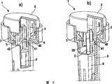
图3a表示该剖切装置的外壳(9),其中,该外壳内部可以通过示意性表示的该外壳壁中的断开部分观察。外壳(9)是通过释放按钮(2)和盖子(10)封闭的。钩子(3)作为旋转驱动部件与释放按钮(2)连接。由弹簧(4)驱动的剌血针保持器(6)位于该外壳内部。刺血针保持器(6)具有一个扭接杆(5)形式的承载部件,通过该部件将刺血针保持器(6)安装在外壳(9)的支承表面(20)上。该外壳的支承表面(20)具有一个凹陷,它有利于承载部件在支承表面上的定位。当承载部件(5)保持在支承表面(20)上时,弹簧(4)是压缩的。此时,旋转驱动部件(3)位于靠近承载部件处。通过沿图3a中箭头所示的剖切方向按压释放按钮(2)来触发剖切过程。在该过程中,当释放按钮被下压并且接合在支承表面(20)的凹陷中时,小的弹性钩子(3)变形,以便刺血针保持器旋转,并且使承载部件(5)从支承表面上降落,如图3b所示。该降落运动导致刺血针保持器(6)沿剖切方向运动,由此松开弹簧(4)。刺血针保持器的降落运动一直持续到在外壳(9)内到达止动部件(30)为止,该止动部件受到承载部件(5)的撞击,并且阻止刺血针保持器的降落运动。其结果是,刺血针顶端(21)从该外壳的开口(未示出)露出。刺血针顶端(21)从外壳中露出的程度可以通过盖子(10)改变,因此,正如已经披露的,该盖子能够调整抽血装置的穿刺深度。通过回复弹簧(8)将刺血针顶端收回该外壳中,以便在刺穿皮肤的一个部位之后,刺血针不再保留在身体部位中。Figure 3a shows the housing (9) of the sectioning device, wherein the interior of the housing can be viewed through a schematically indicated cutout in the housing wall. The housing (9) is closed by the release button (2) and the cover (10). The hook (3) is connected to the release button (2) as a rotary drive part. A lancet holder (6) driven by a spring (4) is located inside the housing. The lancet holder ( 6 ) has a carrier part in the form of a twist rod ( 5 ), by means of which the lancet holder ( 6 ) is mounted on the bearing surface ( 20 ) of the housing ( 9 ). The support surface (20) of the housing has a recess which facilitates the positioning of the carrier part on the support surface. The spring (4) is compressed when the load bearing part (5) is held on the bearing surface (20). At this time, the rotary drive part (3) is located close to the carrying part. The sectioning process is triggered by pressing the release button (2) in the sectioning direction indicated by the arrow in Figure 3a. During this process, when the release button is depressed and engages in the recess of the support surface (20), the small elastic hook (3) is deformed so that the lancet holder rotates and the carrier part (5) is lifted from the support surface (20). landing on the surface, as shown in Figure 3b. This lowering movement causes the lancet holder (6) to move in the cutting direction, thereby releasing the spring (4). The lowering movement of the lancet holder continues until a stop part (30) is reached in the housing (9), which is struck by the carrier part (5) and prevents the lowering movement of the lancet holder. As a result, the lancet tip (21) emerges from an opening (not shown) of the housing. The extent to which the lancet tip (21) emerges from the housing can be varied by means of the cover (10), thus enabling adjustment of the puncture depth of the blood-drawing device, as already disclosed. The lancet tip is retracted into the housing by means of a return spring (8), so that the lancet no longer remains in the body part after piercing a part of the skin.
图4表示具有类似于在图1-3中已经示出的结构的抽血装置。所示出的该装置具有一个侧面开口,以便显示用于调节穿刺深度的机构的例子。图4所示的剖切装置表示这样一种状态,其中,刺血针从外壳(9)的下端突出。在通过释放按钮(2)启动剖切过程之后,刺血针保持器(6)沿剖切方向降落。降落运动一直进行到刺血针保持器(6)撞击在外壳(9)的止动部件(30)上为止,以便阻止该降落运动。在所示出的例子中,被用于将刺血针保持器支承在支承表面(20)上的承载部件(5)还被用作相对止动部件(30)的对接法兰。因此不需要其他结构措施来限定刺血针保持器的降落运动。在所示出的剖切装置中,止动部件(30)是外壳(9)的不可改变的一个部件。在这些条件下,刺血针保持器降落所沿的路径独立于所选择的穿刺深度。这样能确保在每一次穿刺过程中具有恒定的力矩。为了改变穿刺深度,如图4中的箭头(31)所示,可以沿着剖切方向或与之相反的方向移动可移动地安装在外壳(9)上的盖子(10)。因此,通过旋转盖子(10)可以改变外壳(9)的止动部件(30)和盖子(10)的开口之间的距离,剌血针将从该开口中露出。止动部件(30)和该开口之间的距离在图4中用箭头(32)表示。因此,刺血针从该外壳中突出的程度是由该距离限定的。在改变穿刺深度时,可以用若干种方法沿路径(31)对该盖子进行定位。例如,这一目的可以通过相对该外壳旋转该盖子而实现。不过,对于盖子(10)来说,还可以通过沿方向(31)拉动或推动而使它向着或远离止动部件(30)运动。一般,可以用无数种不同的方式或者有限的步骤对盖子(10)进行定位。另外,已经证实对于该剖切装置来说具有锁定部件(未示出)是有利的,由该锁定部件将该盖子保持在预定位置上,以便当盖子(10)被放置在身体部位上时它不会移动。在一种优选实施方案中,所得到的刺血针穿刺深度通过一个刻度尺显示给用户。原则上讲,有多种机构可用于调整穿刺深度。Fig. 4 shows a blood drawing device having a structure similar to that already shown in Figs. 1-3. The device is shown with a side opening to show an example of a mechanism for adjusting the penetration depth. The cutting device shown in Fig. 4 shows a state in which the lancet protrudes from the lower end of the housing (9). After starting the sectioning process by releasing the button (2), the lancet holder (6) is lowered in the sectioning direction. The lowering movement continues until the lancet holder ( 6 ) hits the stop part ( 30 ) of the housing ( 9 ), in order to prevent this lowering movement. In the example shown, the carrier part ( 5 ) used for supporting the lancet holder on the bearing surface ( 20 ) is also used as counter-flange against the stop part ( 30 ). No further structural measures are therefore required to limit the lowering movement of the lancet holder. In the sectioning device shown, the stop element (30) is an unalterable part of the housing (9). Under these conditions, the path along which the lancet holder is lowered is independent of the selected puncture depth. This ensures a constant torque during each penetration. In order to change the penetration depth, the cover (10), which is movably mounted on the housing (9), can be moved in the cutting direction or in the opposite direction, as indicated by the arrow (31) in Figure 4 . Thus, by rotating the cover (10) it is possible to change the distance between the stop part (30) of the casing (9) and the opening of the cover (10) from which the lancet will emerge. The distance between the stop member ( 30 ) and this opening is indicated by arrow ( 32 ) in FIG. 4 . Thus, the extent to which the lancet protrudes from the housing is defined by this distance. The cap can be positioned along the path (31) in several ways while varying the penetration depth. For example, this can be achieved by rotating the cover relative to the housing. However, it is also possible for the lid (10) to be moved towards or away from the stop member (30) by pulling or pushing in direction (31). In general, the lid (10) can be positioned in an infinite number of different ways or in a limited number of steps. In addition, it has proven to be advantageous for the dissection device to have locking means (not shown) which hold the cover in a predetermined position so that when the cover (10) is placed on the body part it will won't move. In a preferred embodiment, the resulting lancet penetration depth is displayed to the user via a scale. In principle, there are various mechanisms for adjusting the penetration depth.
例如,在专利US4895147中披露了一种用于调整穿刺深度的机构。在这种情况下,该抽血装置的穿刺深度是通过沿着剖切装置的剖切方向或与之相反的方向移动刺血针外壳的止动部件而进行调整的。在这种情况下,刺血针保持器与一个控制部件连接,当触发剖切过程时,该控制部件降落在止动部件上,以便阻止刺血针保持器的降落运动。刺血针保持器降落所沿的路径的长度是在该机构中根据可移动止动部件的位置决定的。因此,根据穿刺深度产生了不同的作用力矩。For example, a mechanism for adjusting the puncture depth is disclosed in the patent US4895147. In this case, the piercing depth of the blood drawing device is adjusted by moving the stop part of the lancet housing in the cutting direction of the cutting device or in the opposite direction thereto. In this case, the lancet holder is connected to a control part which, when the cutting process is triggered, falls on the stop part in order to prevent the lowering movement of the lancet holder. The length of the path along which the lancet holder is lowered is determined in the mechanism according to the position of the movable stop. As a result, different acting moments are generated depending on the penetration depth.
专利文献US6056765披露了用于改变抽血装置的穿刺深度的另一种机构。在这种情况下,刺血针可移动地安装在刺血针保持器上。通过将针插入刺血针保持器内不同的距离来改变穿刺深度,而刺血针保持器的止动部件永久定位在该外壳中。Patent document US6056765 discloses another mechanism for changing the puncture depth of a blood drawing device. In this case, the lancet is movably mounted on the lancet holder. The penetration depth is varied by inserting the needle at different distances into the lancet holder, with the stop part of the lancet holder permanently positioned in the housing.
由于该剖切装置的触发机构会表现出对这样的机构的限制,但是因为该抽血装置对于该剖切装置没有提出任何进一步的要求,所以原则上讲,有多种用于调整穿刺深度的方法。Since the triggering mechanism of the cutting device presents a limitation to such a mechanism, but because the blood drawing device does not place any further demands on the cutting device, in principle there are various options for adjusting the puncture depth. method.
图5表示能阻止意外触发剖切过程的锁定机构的例子。图5表示外壳(9)的上部,它起着触发剖切过程的作用。为了防止意外触发,除了释放按钮(2)和旋转驱动部件(3)之外,触发单元(1)还具有一个锁定部件(40)。锁定部件(40)是一个延伸入外壳(9)内部的杆的形式。如果没有启动释放按钮的话,杆(40)就位于外壳(9)和刺血针保持器(6)之间。刺血针保持器(6)具有一个切口(42),锁定部件(40)就接合在该切口中。所述定位阻止了刺血针保持器的旋转。当沿剖切方向按压释放按钮时,锁定部件(40)只压靠在外壳(9)的倾斜表面(41)上。释放按钮上的进一步的压力会引导锁定部件沿斜面(41)移动,并使它向外扩展。锁定部件的侧向拉伸能达到这样的程度,使得该杆不再能接合在刺血针保持器的切口(42)内。与此同时,保持臂(3)压靠在承载部件(5)上并且转动剌血针保持器,此时,刺血针保持器不再受到锁定部件(40)的限制。该转动一直进行到承载部件(5)从外壳的支承表面上降落并且触发剖切过程为止。在这种情况下,正如已经披露的,支承表面(20)具有一个凹陷,该承载部件就定位于该凹陷中。不过,该支承表面上的这种凹陷还可以省略,因为该锁定部件能确保将承载部件可靠地安装在支承表面上。如果省略了支承表面上的这种凹陷,举例来说,这样一来的优点是在生产抽血装置时允许具有更大的公差,因为不再需要使刺血针保持器精确适应该外壳。因此,降低了这种抽血装置的生产成本。Figure 5 shows an example of a locking mechanism that prevents accidental triggering of the sectioning process. Figure 5 shows the upper part of the housing (9), which acts as a trigger for the cutting process. In order to prevent accidental triggering, the triggering unit (1) has a locking part (40) in addition to the release button (2) and the rotary drive part (3). The locking member (40) is in the form of a rod extending into the interior of the housing (9). If the release button is not actuated, the rod (40) is located between the housing (9) and the lancet holder (6). The lancet holder (6) has a cutout (42) in which the locking part (40) engages. Said positioning prevents rotation of the lancet holder. When the release button is pressed in the sectioning direction, the locking part (40) only presses against the inclined surface (41) of the housing (9). Further pressure on the release button will guide the locking member along the ramp (41) and cause it to expand outwards. The lateral stretching of the locking part can reach such an extent that the rod can no longer engage in the cutout (42) of the lancet holder. At the same time, the holding arm (3) presses against the carrying part (5) and turns the lancet holder, at which point the lancet holder is no longer restricted by the locking part (40). This rotation continues until the carrier part ( 5 ) drops from the supporting surface of the housing and triggers the cutting process. In this case, as already disclosed, the support surface ( 20 ) has a recess in which the carrier part is positioned. However, such a recess on the bearing surface can also be omitted, since the locking element ensures a secure mounting of the carrier element on the bearing surface. If such a depression on the bearing surface is omitted, this has the advantage, for example, of allowing greater tolerances in the production of the blood drawing device, since it is no longer necessary to precisely adapt the lancet holder to the housing. Thus, the production costs of such a blood drawing device are reduced.
除了已经披露的锁定装置之外,该锁定机构还表示一种优选实施方案。不过原则上讲,能阻止意外触发剖切过程的任何实施方案都是可行的。这一目的优选是这样实现的:刺血针保持器相对支承表面的旋转运动受到了抑制。In addition to the locking device already disclosed, this locking mechanism also represents a preferred embodiment. In principle, however, any embodiment is possible which prevents accidental triggering of the sectioning process. This object is preferably achieved in that a rotational movement of the lancet holder relative to the bearing surface is prevented.
Claims (23)
Translated fromChineseApplications Claiming Priority (2)
| Application Number | Priority Date | Filing Date | Title |
|---|---|---|---|
| DE10222235.5 | 2002-05-16 | ||
| DE10222235ADE10222235A1 (en) | 2002-05-16 | 2002-05-16 | Blood Collection system |
Publications (2)
| Publication Number | Publication Date |
|---|---|
| CN1462608Atrue CN1462608A (en) | 2003-12-24 |
| CN100401982C CN100401982C (en) | 2008-07-16 |
Family
ID=29285584
Family Applications (1)
| Application Number | Title | Priority Date | Filing Date |
|---|---|---|---|
| CNB03123819XAExpired - LifetimeCN100401982C (en) | 2002-05-16 | 2003-05-16 | blood pumping device |
Country Status (14)
| Country | Link |
|---|---|
| US (1) | US7238192B2 (en) |
| EP (1) | EP1371329B1 (en) |
| JP (2) | JP3993529B2 (en) |
| KR (2) | KR100819399B1 (en) |
| CN (1) | CN100401982C (en) |
| AT (1) | ATE540614T1 (en) |
| AU (1) | AU2003204154B2 (en) |
| BR (1) | BR0301333A (en) |
| CA (1) | CA2428510C (en) |
| DE (1) | DE10222235A1 (en) |
| ES (1) | ES2379064T3 (en) |
| MX (1) | MXPA03004254A (en) |
| PL (1) | PL209556B1 (en) |
| SG (1) | SG120929A1 (en) |
Cited By (4)
| Publication number | Priority date | Publication date | Assignee | Title |
|---|---|---|---|---|
| CN103987318A (en)* | 2011-12-19 | 2014-08-13 | 格雷斯海姆雷根斯堡股份有限公司 | Lancing device for taking blood samples |
| CN108697854A (en)* | 2016-02-29 | 2018-10-23 | 欧弗洛有限公司 | Liquid injection device |
| CN109069726A (en)* | 2016-03-11 | 2018-12-21 | 欧弗洛有限公司 | Chemical fluid injection device |
| CN114229431A (en)* | 2021-11-11 | 2022-03-25 | 奔腾激光(武汉)有限公司 | Laser cutting auxiliary blanking system |
Families Citing this family (111)
| Publication number | Priority date | Publication date | Assignee | Title |
|---|---|---|---|---|
| US6036924A (en) | 1997-12-04 | 2000-03-14 | Hewlett-Packard Company | Cassette of lancet cartridges for sampling blood |
| US6391005B1 (en) | 1998-03-30 | 2002-05-21 | Agilent Technologies, Inc. | Apparatus and method for penetration with shaft having a sensor for sensing penetration depth |
| US8641644B2 (en) | 2000-11-21 | 2014-02-04 | Sanofi-Aventis Deutschland Gmbh | Blood testing apparatus having a rotatable cartridge with multiple lancing elements and testing means |
| US9795747B2 (en) | 2010-06-02 | 2017-10-24 | Sanofi-Aventis Deutschland Gmbh | Methods and apparatus for lancet actuation |
| US7749174B2 (en) | 2001-06-12 | 2010-07-06 | Pelikan Technologies, Inc. | Method and apparatus for lancet launching device intergrated onto a blood-sampling cartridge |
| US8337419B2 (en) | 2002-04-19 | 2012-12-25 | Sanofi-Aventis Deutschland Gmbh | Tissue penetration device |
| WO2002101359A2 (en) | 2001-06-12 | 2002-12-19 | Pelikan Technologies, Inc. | Integrated blood sampling analysis system with multi-use sampling module |
| US7981056B2 (en) | 2002-04-19 | 2011-07-19 | Pelikan Technologies, Inc. | Methods and apparatus for lancet actuation |
| US9226699B2 (en) | 2002-04-19 | 2016-01-05 | Sanofi-Aventis Deutschland Gmbh | Body fluid sampling module with a continuous compression tissue interface surface |
| US7041068B2 (en) | 2001-06-12 | 2006-05-09 | Pelikan Technologies, Inc. | Sampling module device and method |
| EP1395185B1 (en) | 2001-06-12 | 2010-10-27 | Pelikan Technologies Inc. | Electric lancet actuator |
| JP4209767B2 (en) | 2001-06-12 | 2009-01-14 | ペリカン テクノロジーズ インコーポレイテッド | Self-optimized cutting instrument with adaptive means for temporary changes in skin properties |
| AU2002344825A1 (en) | 2001-06-12 | 2002-12-23 | Pelikan Technologies, Inc. | Method and apparatus for improving success rate of blood yield from a fingerstick |
| JP4272051B2 (en) | 2001-06-12 | 2009-06-03 | ペリカン テクノロジーズ インコーポレイテッド | Blood sampling apparatus and method |
| US9427532B2 (en) | 2001-06-12 | 2016-08-30 | Sanofi-Aventis Deutschland Gmbh | Tissue penetration device |
| US7344507B2 (en) | 2002-04-19 | 2008-03-18 | Pelikan Technologies, Inc. | Method and apparatus for lancet actuation |
| US7344894B2 (en) | 2001-10-16 | 2008-03-18 | Agilent Technologies, Inc. | Thermal regulation of fluidic samples within a diagnostic cartridge |
| US7909778B2 (en) | 2002-04-19 | 2011-03-22 | Pelikan Technologies, Inc. | Method and apparatus for penetrating tissue |
| US7901362B2 (en) | 2002-04-19 | 2011-03-08 | Pelikan Technologies, Inc. | Method and apparatus for penetrating tissue |
| US7892183B2 (en) | 2002-04-19 | 2011-02-22 | Pelikan Technologies, Inc. | Method and apparatus for body fluid sampling and analyte sensing |
| US9795334B2 (en) | 2002-04-19 | 2017-10-24 | Sanofi-Aventis Deutschland Gmbh | Method and apparatus for penetrating tissue |
| US7229458B2 (en) | 2002-04-19 | 2007-06-12 | Pelikan Technologies, Inc. | Method and apparatus for penetrating tissue |
| US7297122B2 (en) | 2002-04-19 | 2007-11-20 | Pelikan Technologies, Inc. | Method and apparatus for penetrating tissue |
| US7244265B2 (en) | 2002-04-19 | 2007-07-17 | Pelikan Technologies, Inc. | Method and apparatus for penetrating tissue |
| US7331931B2 (en) | 2002-04-19 | 2008-02-19 | Pelikan Technologies, Inc. | Method and apparatus for penetrating tissue |
| US8372016B2 (en) | 2002-04-19 | 2013-02-12 | Sanofi-Aventis Deutschland Gmbh | Method and apparatus for body fluid sampling and analyte sensing |
| US8579831B2 (en) | 2002-04-19 | 2013-11-12 | Sanofi-Aventis Deutschland Gmbh | Method and apparatus for penetrating tissue |
| US7648468B2 (en) | 2002-04-19 | 2010-01-19 | Pelikon Technologies, Inc. | Method and apparatus for penetrating tissue |
| US7491178B2 (en) | 2002-04-19 | 2009-02-17 | Pelikan Technologies, Inc. | Method and apparatus for penetrating tissue |
| WO2003088824A2 (en) | 2002-04-19 | 2003-10-30 | Pelikan Technologies, Inc. | Device and method for variable speed lancet |
| US8784335B2 (en) | 2002-04-19 | 2014-07-22 | Sanofi-Aventis Deutschland Gmbh | Body fluid sampling device with a capacitive sensor |
| US8267870B2 (en) | 2002-04-19 | 2012-09-18 | Sanofi-Aventis Deutschland Gmbh | Method and apparatus for body fluid sampling with hybrid actuation |
| US7976476B2 (en) | 2002-04-19 | 2011-07-12 | Pelikan Technologies, Inc. | Device and method for variable speed lancet |
| US7374544B2 (en) | 2002-04-19 | 2008-05-20 | Pelikan Technologies, Inc. | Method and apparatus for penetrating tissue |
| US7485128B2 (en) | 2002-04-19 | 2009-02-03 | Pelikan Technologies, Inc. | Method and apparatus for penetrating tissue |
| US8360992B2 (en) | 2002-04-19 | 2013-01-29 | Sanofi-Aventis Deutschland Gmbh | Method and apparatus for penetrating tissue |
| US7232451B2 (en) | 2002-04-19 | 2007-06-19 | Pelikan Technologies, Inc. | Method and apparatus for penetrating tissue |
| US7524293B2 (en) | 2002-04-19 | 2009-04-28 | Pelikan Technologies, Inc. | Method and apparatus for penetrating tissue |
| US9314194B2 (en) | 2002-04-19 | 2016-04-19 | Sanofi-Aventis Deutschland Gmbh | Tissue penetration device |
| US7563232B2 (en) | 2002-04-19 | 2009-07-21 | Pelikan Technologies, Inc. | Method and apparatus for penetrating tissue |
| US8221334B2 (en) | 2002-04-19 | 2012-07-17 | Sanofi-Aventis Deutschland Gmbh | Method and apparatus for penetrating tissue |
| US7717863B2 (en) | 2002-04-19 | 2010-05-18 | Pelikan Technologies, Inc. | Method and apparatus for penetrating tissue |
| US7547287B2 (en) | 2002-04-19 | 2009-06-16 | Pelikan Technologies, Inc. | Method and apparatus for penetrating tissue |
| US7371247B2 (en) | 2002-04-19 | 2008-05-13 | Pelikan Technologies, Inc | Method and apparatus for penetrating tissue |
| US7291117B2 (en) | 2002-04-19 | 2007-11-06 | Pelikan Technologies, Inc. | Method and apparatus for penetrating tissue |
| US8702624B2 (en) | 2006-09-29 | 2014-04-22 | Sanofi-Aventis Deutschland Gmbh | Analyte measurement device with a single shot actuator |
| US9248267B2 (en) | 2002-04-19 | 2016-02-02 | Sanofi-Aventis Deustchland Gmbh | Tissue penetration device |
| US7708701B2 (en) | 2002-04-19 | 2010-05-04 | Pelikan Technologies, Inc. | Method and apparatus for a multi-use body fluid sampling device |
| US7410468B2 (en) | 2002-04-19 | 2008-08-12 | Pelikan Technologies, Inc. | Method and apparatus for penetrating tissue |
| US7141058B2 (en) | 2002-04-19 | 2006-11-28 | Pelikan Technologies, Inc. | Method and apparatus for a body fluid sampling device using illumination |
| US7674232B2 (en) | 2002-04-19 | 2010-03-09 | Pelikan Technologies, Inc. | Method and apparatus for penetrating tissue |
| JP4250695B2 (en)* | 2002-07-02 | 2009-04-08 | アークレイ株式会社 | Method for setting puncture member to puncture device, and puncture device |
| US8574895B2 (en) | 2002-12-30 | 2013-11-05 | Sanofi-Aventis Deutschland Gmbh | Method and apparatus using optical techniques to measure analyte levels |
| DE602004028463D1 (en) | 2003-05-30 | 2010-09-16 | Pelikan Technologies Inc | METHOD AND DEVICE FOR INJECTING LIQUID |
| US7850621B2 (en) | 2003-06-06 | 2010-12-14 | Pelikan Technologies, Inc. | Method and apparatus for body fluid sampling and analyte sensing |
| WO2006001797A1 (en) | 2004-06-14 | 2006-01-05 | Pelikan Technologies, Inc. | Low pain penetrating |
| EP1635700B1 (en) | 2003-06-13 | 2016-03-09 | Sanofi-Aventis Deutschland GmbH | Apparatus for a point of care device |
| US8282576B2 (en) | 2003-09-29 | 2012-10-09 | Sanofi-Aventis Deutschland Gmbh | Method and apparatus for an improved sample capture device |
| EP1680014A4 (en) | 2003-10-14 | 2009-01-21 | Pelikan Technologies Inc | METHOD AND DEVICE FOR A VARIABLE USER INTERFACE |
| US7822454B1 (en) | 2005-01-03 | 2010-10-26 | Pelikan Technologies, Inc. | Fluid sampling device with improved analyte detecting member configuration |
| US8668656B2 (en) | 2003-12-31 | 2014-03-11 | Sanofi-Aventis Deutschland Gmbh | Method and apparatus for improving fluidic flow and sample capture |
| JP2007521122A (en)* | 2004-02-06 | 2007-08-02 | バイエル・ヘルスケア・エルエルシー | Braking and telescopic mechanism for lancing device |
| WO2005089333A2 (en)* | 2004-03-15 | 2005-09-29 | Oakville Hong Kong Company Limited | Lancet device and method of use |
| US9101302B2 (en)* | 2004-05-03 | 2015-08-11 | Abbott Diabetes Care Inc. | Analyte test device |
| US9066688B2 (en) | 2004-05-07 | 2015-06-30 | Becton, Dickinson And Company | Contact activated lancet device |
| US9380975B2 (en) | 2004-05-07 | 2016-07-05 | Becton, Dickinson And Company | Contact activated lancet device |
| CN100528080C (en)* | 2004-05-07 | 2009-08-19 | 贝克顿·迪金森公司 | Rotary actuated medical puncturing device |
| WO2006011062A2 (en) | 2004-05-20 | 2006-02-02 | Albatros Technologies Gmbh & Co. Kg | Printable hydrogel for biosensors |
| US9775553B2 (en) | 2004-06-03 | 2017-10-03 | Sanofi-Aventis Deutschland Gmbh | Method and apparatus for a fluid sampling device |
| WO2005120365A1 (en) | 2004-06-03 | 2005-12-22 | Pelikan Technologies, Inc. | Method and apparatus for a fluid sampling device |
| US7512432B2 (en)* | 2004-07-27 | 2009-03-31 | Abbott Laboratories | Sensor array |
| EP1841359A1 (en)* | 2004-09-09 | 2007-10-10 | Bayer Healthcare, LLC | Damping system for a lancet using compressed air |
| US8652831B2 (en) | 2004-12-30 | 2014-02-18 | Sanofi-Aventis Deutschland Gmbh | Method and apparatus for analyte measurement test time |
| US8784444B2 (en)* | 2005-03-04 | 2014-07-22 | Bayer Healthcare Llc | Lancet release mechanism |
| CN101163446A (en) | 2005-03-04 | 2008-04-16 | 拜尔保健有限公司 | Lancet-release mechanism |
| PL2425776T3 (en)* | 2005-04-07 | 2013-12-31 | Becton Dickinson Co | Lancet device |
| WO2006110573A1 (en)* | 2005-04-07 | 2006-10-19 | Becton, Dickinson And Company | Trigger activated lancet |
| JP4371079B2 (en)* | 2005-05-16 | 2009-11-25 | ソニー株式会社 | Switch mechanism and electronic equipment |
| KR100716015B1 (en)* | 2005-06-08 | 2007-05-08 | 유재천 | Lancet device and blood collection and injection method using the same |
| PL375837A1 (en)* | 2005-06-22 | 2006-12-27 | Htl Strefa Sp Z Oo | Apparatus for puncturing patient's skin |
| EP1903927A2 (en)* | 2005-06-30 | 2008-04-02 | Bayer Healthcare, LLC | Single-puncture lancing system |
| WO2007005665A1 (en)* | 2005-06-30 | 2007-01-11 | Bayer Healthcare Llc | Single-puncture lancing system |
| US8048098B2 (en)* | 2005-07-14 | 2011-11-01 | Bayer Healthcare Llc | Lancing device for one skin puncture |
| US8617195B2 (en)* | 2005-08-04 | 2013-12-31 | Bayer Healthcare Llc | Lancing device |
| US8469984B2 (en)* | 2005-10-25 | 2013-06-25 | Bayer Healthcare Llc | Single use lancing device |
| DE502006001024D1 (en) | 2006-01-10 | 2008-08-14 | Roche Diagnostics Gmbh | Lancing device with reuse protection |
| JPWO2007145204A1 (en)* | 2006-06-13 | 2009-10-29 | 泉株式会社 | Lancet assembly |
| GB2440119A (en)* | 2006-07-18 | 2008-01-23 | Owen Mumford Ltd | Skin Pricking Device |
| DE102006049800B4 (en)* | 2006-10-23 | 2010-12-16 | Amadeus Dr. med. Hornemann | Device for taking blood |
| WO2008064333A2 (en)* | 2006-11-21 | 2008-05-29 | Stat Medical Devices, Inc. | Lancet device utilizing a revolver-type cartridge, revolver-type cartridge, and method of making and/or using the cartridge and the lancet device |
| US8303615B2 (en)* | 2007-03-12 | 2012-11-06 | Bayer Healthcare Llc | Lancet-eject mechanism |
| PL213006B1 (en)* | 2007-04-19 | 2012-12-31 | Htl Strefa Spolka Akcyjna | Device for needling of patient's skin |
| ES2354912T3 (en)* | 2007-05-16 | 2011-03-21 | Roche Diagnostics Gmbh | PUNCTURE SYSTEM |
| US20090099437A1 (en)* | 2007-10-11 | 2009-04-16 | Vadim Yuzhakov | Lancing Depth Adjustment Via Moving Cap |
| EP2265324B1 (en) | 2008-04-11 | 2015-01-28 | Sanofi-Aventis Deutschland GmbH | Integrated analyte measurement system |
| US9375169B2 (en) | 2009-01-30 | 2016-06-28 | Sanofi-Aventis Deutschland Gmbh | Cam drive for managing disposable penetrating member actions with a single motor and motor and control system |
| US8262685B2 (en)* | 2009-03-27 | 2012-09-11 | Nipro Corporation | Disposable lancing device |
| US9044177B2 (en) | 2009-10-07 | 2015-06-02 | Asahi Polyslider Company, Limited | Lancet pricking device |
| US8965476B2 (en) | 2010-04-16 | 2015-02-24 | Sanofi-Aventis Deutschland Gmbh | Tissue penetration device |
| JP5514008B2 (en) | 2010-06-22 | 2014-06-04 | ニプロ株式会社 | Disposable puncture device |
| JP5615125B2 (en)* | 2010-10-15 | 2014-10-29 | 株式会社旭ポリスライダー | Lancet lancing device |
| US20130211289A1 (en) | 2012-01-25 | 2013-08-15 | Tasso, Inc. | Handheld Device for Drawing, Collecting, and Analyzing Bodily Fluid |
| WO2014083783A1 (en) | 2012-11-30 | 2014-06-05 | パナソニックヘルスケア株式会社 | Puncture instrument, puncture needle cartridge mounted in puncture instrument, and method for using puncture instrument and puncture needle cartridge |
| EP2823762B1 (en)* | 2013-07-08 | 2015-08-19 | Roche Diagniostics GmbH | Lancing actuator |
| JP5686215B2 (en)* | 2014-03-28 | 2015-03-18 | ニプロ株式会社 | Disposable puncture device |
| JP6640830B2 (en) | 2014-07-18 | 2020-02-05 | ベクトン・ディキンソン・アンド・カンパニーBecton, Dickinson And Company | Lancet device for removing first droplet |
| CN106999120B (en) | 2014-08-01 | 2021-05-14 | 塔索公司 | Devices, systems, and methods for gravity-enhanced microfluidic collection, handling, and delivery of liquids |
| CA3009328C (en)* | 2015-12-21 | 2024-03-05 | Tasso, Inc. | Devices, systems and methods for actuation and retraction in fluid collection |
| JP7460607B2 (en) | 2018-09-14 | 2024-04-02 | タッソ インコーポレイテッド | Body fluid collection devices and related methods |
| CN109259773B (en)* | 2018-10-19 | 2024-06-11 | 宁波美生医疗器材有限公司 | Push type blood taking needle |
| CN112336345A (en)* | 2020-10-27 | 2021-02-09 | 王�华 | Be applied to portable blood sampling device of blood glucose meter |
Family Cites Families (58)
| Publication number | Priority date | Publication date | Assignee | Title |
|---|---|---|---|---|
| US3030959A (en) | 1959-09-04 | 1962-04-24 | Praemeta | Surgical lancet for blood sampling |
| US3244317A (en) | 1962-10-26 | 1966-04-05 | Philip Morris Inc | Blade dispenser |
| US3696915A (en) | 1970-11-12 | 1972-10-10 | Colgate Palmolive Co | Blade dispenser |
| US3833146A (en) | 1973-02-22 | 1974-09-03 | Philip Morris Inc | Magazine holding razor blade cartridges in floating manner |
| DE2803345C2 (en) | 1978-01-26 | 1980-02-14 | Emil 7507 Pfinztal Eisinger | Blood sampling device |
| DE3011211A1 (en) | 1980-03-22 | 1981-10-01 | Clinicon Mannheim GmbH, 6800 Mannheim | BLOOD PLANT DEVICE FOR TAKING BLOOD FOR DIAGNOSTIC PURPOSES |
| US4535769A (en) | 1981-03-23 | 1985-08-20 | Becton, Dickinson And Company | Automatic retractable lancet assembly |
| US4416279A (en)* | 1981-06-19 | 1983-11-22 | Lindner James A | Capillary blood sampling device |
| FR2508305B1 (en)* | 1981-06-25 | 1986-04-11 | Slama Gerard | DEVICE FOR CAUSING A LITTLE BITE TO COLLECT A BLOOD DROP |
| AU549690B2 (en)* | 1981-06-29 | 1986-02-06 | Sherwood Services Ag | Pin prick device to pierce skin |
| US4653513A (en) | 1985-08-09 | 1987-03-31 | Dombrowski Mitchell P | Blood sampler |
| GB8618578D0 (en) | 1986-07-30 | 1986-09-10 | Turner R C | Lancet device |
| US4821878A (en) | 1986-10-08 | 1989-04-18 | Prd Corporation | Round dispenser for sutures |
| US4794926A (en) | 1986-11-24 | 1989-01-03 | Invictus, Inc. | Lancet cartridge |
| US4735203A (en) | 1986-12-12 | 1988-04-05 | Ryder International Corporation | Retractable lancet |
| DE3710774A1 (en) | 1987-03-31 | 1988-10-13 | Gerhard Arnold | NAILS FOR HANGING IMAGES OR THE LIKE, AND NAILERS FOR DRIVING THE SAME |
| US4998452A (en) | 1988-03-25 | 1991-03-12 | Blum Kurt E | Cartridge and magazine apparatus for storage and automatic feed of screw fasteners |
| US4895147A (en) | 1988-10-28 | 1990-01-23 | Sherwood Medical Company | Lancet injector |
| US5035704A (en) | 1989-03-07 | 1991-07-30 | Lambert Robert D | Blood sampling mechanism |
| US5105823A (en) | 1990-04-05 | 1992-04-21 | Blum Alvin S | Shielded replaceable lancet blade assembly |
| US5152775A (en) | 1990-10-04 | 1992-10-06 | Norbert Ruppert | Automatic lancet device and method of using the same |
| US5578053A (en)* | 1993-06-24 | 1996-11-26 | Yoon; Inbae | Safety needle instrument having a triggered safety member |
| CA2123400A1 (en)* | 1991-11-12 | 1993-05-27 | Urs A. Ramel | Lancet device |
| US5496340A (en) | 1992-01-24 | 1996-03-05 | Leonard Bloom | Combination guarded surgical scalpel and blade stripper |
| DE4212315A1 (en) | 1992-04-13 | 1993-10-14 | Boehringer Mannheim Gmbh | Blood lancet device for drawing blood for diagnostic purposes |
| PL169210B1 (en) | 1992-08-03 | 1996-06-28 | Przed Zagraniczne Htl | Puncturing device |
| US5269800A (en) | 1992-12-10 | 1993-12-14 | Davis Manufacturing Systems Inc. | Blood lancing device |
| KR960005604Y1 (en) | 1992-12-23 | 1996-07-10 | 조영서 | Painless bleeding by momentary operation |
| KR960010241Y1 (en) | 1993-06-02 | 1996-12-04 | 이종홍 | Automatic acupuncture device |
| DE4320463A1 (en) | 1993-06-21 | 1994-12-22 | Boehringer Mannheim Gmbh | Blood lancet device for drawing blood for diagnostic purposes |
| US5464418A (en) | 1993-12-09 | 1995-11-07 | Schraga; Steven | Reusable lancet device |
| KR960010335Y1 (en) | 1993-12-28 | 1996-12-10 | 조영서 | Painless bleeding by momentary operation |
| US5527334A (en) | 1994-05-25 | 1996-06-18 | Ryder International Corporation | Disposable, retractable lancet |
| US5514152A (en) | 1994-08-16 | 1996-05-07 | Specialized Health Products, Inc. | Multiple segment encapsulated medical lancing device |
| US5478345A (en) | 1994-08-19 | 1995-12-26 | United States Surgical Corporation | Mechanism for endoscopic suturing device |
| US5531763A (en) | 1994-10-07 | 1996-07-02 | United States Surgical Corporation | Suture cinching apparatus |
| CA2170560C (en) | 1995-04-17 | 2005-10-25 | Joseph L. Moulton | Means of handling multiple sensors in a glucose monitoring instrument system |
| US5643306A (en) | 1996-03-22 | 1997-07-01 | Stat Medical Devices Inc. | Disposable lancet |
| US5776157A (en) | 1996-10-02 | 1998-07-07 | Specialized Health Products, Inc. | Lancet apparatus and methods |
| US5984940A (en) | 1997-05-29 | 1999-11-16 | Atrion Medical Products, Inc. | Lancet device |
| GB9713077D0 (en)* | 1997-06-21 | 1997-08-27 | Owen Mumford Ltd | Improvements relating to skin prickers |
| US6056765A (en) | 1997-06-24 | 2000-05-02 | Bajaj; Ratan | Lancet device |
| US5868772A (en) | 1997-07-31 | 1999-02-09 | Bayer Corporation | Blood sampling device with anti-twist lancet holder |
| US5829589A (en) | 1997-09-12 | 1998-11-03 | Becton Dickinson And Company | Pen needle magazine dispenser |
| US6036924A (en) | 1997-12-04 | 2000-03-14 | Hewlett-Packard Company | Cassette of lancet cartridges for sampling blood |
| US5908434A (en) | 1998-02-13 | 1999-06-01 | Schraga; Steven | Lancet device |
| US5951582A (en) | 1998-05-22 | 1999-09-14 | Specialized Health Products, Inc. | Lancet apparatus and methods |
| US6346114B1 (en)* | 1998-06-11 | 2002-02-12 | Stat Medical Devices, Inc. | Adjustable length member such as a cap of a lancet device for adjusting penetration depth |
| EP0969443A1 (en)* | 1998-06-29 | 2000-01-05 | Sony Corporation | Image data processing apparatus and methods for image resolution change |
| US7077828B2 (en)* | 1999-03-05 | 2006-07-18 | Roche Diagnostics Gmbh | Device for withdrawing blood for diagnostic applications |
| DE19909602A1 (en)* | 1999-03-05 | 2000-09-07 | Roche Diagnostics Gmbh | Device for drawing blood for diagnostic purposes |
| GB9914355D0 (en) | 1999-06-19 | 1999-08-18 | Owen Mumford Ltd | Improvements relating to blood sampling devices |
| KR200177945Y1 (en)* | 1999-09-17 | 2000-04-15 | 주식회사두이케어 | A disposable sampling device lancets |
| US6358265B1 (en) | 2000-07-18 | 2002-03-19 | Specialized Health Products, Inc. | Single-step disposable safety lancet apparatus and methods |
| AU9682701A (en) | 2000-10-13 | 2002-04-22 | Alza Corp | Microblade array impact applicator |
| US6514270B1 (en)* | 2000-11-10 | 2003-02-04 | Steven Schraga | Single use lancet device |
| EP1408852A4 (en) | 2001-06-13 | 2009-09-09 | Steven Schraga | Single use lancet device |
| US20040039407A1 (en) | 2002-04-29 | 2004-02-26 | Steven Schraga | Lancet device |
- 2002
- 2002-05-16DEDE10222235Apatent/DE10222235A1/ennot_activeCeased
- 2003
- 2003-05-13SGSG200302790Apatent/SG120929A1/enunknown
- 2003-05-13EPEP03010642Apatent/EP1371329B1/ennot_activeExpired - Lifetime
- 2003-05-13ESES03010642Tpatent/ES2379064T3/ennot_activeExpired - Lifetime
- 2003-05-13CACA002428510Apatent/CA2428510C/ennot_activeExpired - Lifetime
- 2003-05-13KRKR1020030030140Apatent/KR100819399B1/ennot_activeExpired - Lifetime
- 2003-05-13AUAU2003204154Apatent/AU2003204154B2/ennot_activeCeased
- 2003-05-13ATAT03010642Tpatent/ATE540614T1/enactive
- 2003-05-13BRBR0301333-2Apatent/BR0301333A/ennot_activeApplication Discontinuation
- 2003-05-14MXMXPA03004254Apatent/MXPA03004254A/enactiveIP Right Grant
- 2003-05-14USUS10/437,717patent/US7238192B2/ennot_activeExpired - Lifetime
- 2003-05-15JPJP2003137847Apatent/JP3993529B2/ennot_activeExpired - Lifetime
- 2003-05-16PLPL360198Apatent/PL209556B1/enunknown
- 2003-05-16CNCNB03123819XApatent/CN100401982C/ennot_activeExpired - Lifetime
- 2005
- 2005-05-12JPJP2005140156Apatent/JP4086859B2/ennot_activeExpired - Lifetime
- 2006
- 2006-02-13KRKR1020060013653Apatent/KR20060023591A/ennot_activeWithdrawn
Cited By (11)
| Publication number | Priority date | Publication date | Assignee | Title |
|---|---|---|---|---|
| CN103987318A (en)* | 2011-12-19 | 2014-08-13 | 格雷斯海姆雷根斯堡股份有限公司 | Lancing device for taking blood samples |
| CN103987318B (en)* | 2011-12-19 | 2016-04-06 | 格雷斯海姆雷根斯堡股份有限公司 | For extracting the blood-taking device of blood sample |
| US9907490B2 (en) | 2011-12-19 | 2018-03-06 | Gerresheimer Regensburg Gmbh | Lancing device for taking blood samples |
| CN108697854A (en)* | 2016-02-29 | 2018-10-23 | 欧弗洛有限公司 | Liquid injection device |
| CN108697854B (en)* | 2016-02-29 | 2021-05-04 | 艺流有限公司 | Liquid injection device |
| CN113082364A (en)* | 2016-02-29 | 2021-07-09 | 艺流有限公司 | Liquid medicine injection device |
| CN109069726A (en)* | 2016-03-11 | 2018-12-21 | 欧弗洛有限公司 | Chemical fluid injection device |
| CN109069726B (en)* | 2016-03-11 | 2021-11-16 | 艺流有限公司 | Chemical fluid injection device |
| CN114082043A (en)* | 2016-03-11 | 2022-02-25 | 艺流有限公司 | Chemical fluid injection device |
| CN114229431A (en)* | 2021-11-11 | 2022-03-25 | 奔腾激光(武汉)有限公司 | Laser cutting auxiliary blanking system |
| CN114229431B (en)* | 2021-11-11 | 2024-03-29 | 奔腾激光(武汉)有限公司 | Auxiliary blanking system for laser cutting |
Also Published As
| Publication number | Publication date |
|---|---|
| KR20030089448A (en) | 2003-11-21 |
| EP1371329B1 (en) | 2012-01-11 |
| BR0301333A (en) | 2004-08-24 |
| JP2003325484A (en) | 2003-11-18 |
| HK1060967A1 (en) | 2004-09-03 |
| JP4086859B2 (en) | 2008-05-14 |
| ATE540614T1 (en) | 2012-01-15 |
| SG120929A1 (en) | 2006-04-26 |
| JP2005261967A (en) | 2005-09-29 |
| EP1371329A1 (en) | 2003-12-17 |
| US7238192B2 (en) | 2007-07-03 |
| CA2428510A1 (en) | 2003-11-16 |
| AU2003204154B2 (en) | 2008-02-07 |
| AU2003204154A1 (en) | 2003-12-04 |
| CN100401982C (en) | 2008-07-16 |
| KR100819399B1 (en) | 2008-04-04 |
| KR20060023591A (en) | 2006-03-14 |
| MXPA03004254A (en) | 2005-11-23 |
| PL360198A1 (en) | 2003-11-17 |
| JP3993529B2 (en) | 2007-10-17 |
| CA2428510C (en) | 2007-07-24 |
| US20030216767A1 (en) | 2003-11-20 |
| DE10222235A1 (en) | 2003-11-27 |
| ES2379064T3 (en) | 2012-04-20 |
| PL209556B1 (en) | 2011-09-30 |
Similar Documents
| Publication | Publication Date | Title |
|---|---|---|
| CN100401982C (en) | blood pumping device | |
| KR101205396B1 (en) | Squeeze-activated medical puncturing device | |
| US9427180B2 (en) | Cam-actuated medical puncturing device and method | |
| WO2005034721A2 (en) | Lancing device end cap with blood-directing contact face | |
| US8221441B2 (en) | Rotary-actuated medical puncturing device | |
| HK1060967B (en) | Blood withdrawal system | |
| US20100036408A1 (en) | Retractable lancet and retraction mechanism for use therewith |
Legal Events
| Date | Code | Title | Description |
|---|---|---|---|
| C06 | Publication | ||
| PB01 | Publication | ||
| C10 | Entry into substantive examination | ||
| SE01 | Entry into force of request for substantive examination | ||
| REG | Reference to a national code | Ref country code:HK Ref legal event code:DE Ref document number:1060967 Country of ref document:HK | |
| C14 | Grant of patent or utility model | ||
| GR01 | Patent grant | ||
| REG | Reference to a national code | Ref country code:HK Ref legal event code:GR Ref document number:1060967 Country of ref document:HK | |
| CX01 | Expiry of patent term | Granted publication date:20080716 | |
| CX01 | Expiry of patent term |