CN1457285A - Heavy-duty tool with rotationally driven disk-shaped hub - Google Patents
Heavy-duty tool with rotationally driven disk-shaped hubDownload PDFInfo
- Publication number
- CN1457285A CN1457285ACN02800301ACN02800301ACN1457285ACN 1457285 ACN1457285 ACN 1457285ACN 02800301 ACN02800301 ACN 02800301ACN 02800301 ACN02800301 ACN 02800301ACN 1457285 ACN1457285 ACN 1457285A
- Authority
- CN
- China
- Prior art keywords
- hub
- plug
- abrasive material
- tool according
- tool
- Prior art date
- Legal status (The legal status is an assumption and is not a legal conclusion. Google has not performed a legal analysis and makes no representation as to the accuracy of the status listed.)
- Granted
Links
- 239000003082abrasive agentSubstances0.000claimsdescription45
- 238000005452bendingMethods0.000claimsdescription17
- 239000000463materialSubstances0.000claimsdescription10
- 238000004519manufacturing processMethods0.000claimsdescription7
- 238000010438heat treatmentMethods0.000claimsdescription4
- 239000002184metalSubstances0.000claimsdescription3
- 239000000853adhesiveSubstances0.000description4
- 230000001070adhesive effectEffects0.000description4
- 238000000034methodMethods0.000description4
- 230000005540biological transmissionEffects0.000description3
- 239000003365glass fiberSubstances0.000description3
- 229910000831SteelInorganic materials0.000description2
- 230000007423decreaseEffects0.000description2
- 230000003247decreasing effectEffects0.000description2
- 230000002787reinforcementEffects0.000description2
- 239000010959steelSubstances0.000description2
- 238000003466weldingMethods0.000description2
- 230000006978adaptationEffects0.000description1
- 238000004026adhesive bondingMethods0.000description1
- 229910010293ceramic materialInorganic materials0.000description1
- 238000005516engineering processMethods0.000description1
- 239000004744fabricSubstances0.000description1
- 230000002349favourable effectEffects0.000description1
- 238000005304joiningMethods0.000description1
- 239000004033plasticSubstances0.000description1
- 229920003023plasticPolymers0.000description1
- 238000004080punchingMethods0.000description1
- 230000007704transitionEffects0.000description1
Images


Classifications
- B—PERFORMING OPERATIONS; TRANSPORTING
- B24—GRINDING; POLISHING
- B24D—TOOLS FOR GRINDING, BUFFING OR SHARPENING
- B24D5/00—Bonded abrasive wheels, or wheels with inserted abrasive blocks, designed for acting only by their periphery; Bushings or mountings therefor
- B24D5/02—Wheels in one piece
- B—PERFORMING OPERATIONS; TRANSPORTING
- B24—GRINDING; POLISHING
- B24D—TOOLS FOR GRINDING, BUFFING OR SHARPENING
- B24D5/00—Bonded abrasive wheels, or wheels with inserted abrasive blocks, designed for acting only by their periphery; Bushings or mountings therefor
- B24D5/16—Bushings; Mountings
Landscapes
- Engineering & Computer Science (AREA)
- Mechanical Engineering (AREA)
- Polishing Bodies And Polishing Tools (AREA)
Abstract
Description
Translated fromChinese现有技术current technology
本发明涉及根据权利要求1前序部分的、具有可被旋转驱动的盘形轮毂的插接式刀具(Einsatzwerkzeug)。The invention relates to an insert tool with a rotationally drivable disk hub according to the preamble of claim 1 .
盘形的插接式刀具、例如用于角磨机的磨削盘或分割盘,通常全部由粘合的磨料组成及具有一个中心圆形缺口,通过缺口插接式刀具借助一个夹紧螺母可在圆周方向构成传力链地及在轴向上形状锁合地被固定在一个角磨机的主轴上。不仅已公知了具有由缺口区域中的金属板组成的增强部分的插接式刀具,而且也公知了无增强部分的插接式刀具。Disc-shaped plug-in tools, such as grinding or dividing discs for angle grinders, generally consist entirely of bonded abrasives and have a central circular recess through which the plug-in tool can be moved with a clamping nut. Forming a force transmission chain in the circumferential direction and form-locking in the axial direction on the spindle of an angle grinder. Not only plug-in knives are known with reinforcements consisting of sheet metal in the region of the cutout, but also plug-in knives without reinforcements.
本发明的优点Advantages of the invention
本发明涉及具有可被旋转驱动的盘形轮毂的插接式刀具,在该轮毂上的径向外部区域上固定一个构成分割盘、磨削盘、粗磨削盘或切割砂轮的磨料。The invention relates to a plug-in tool with a rotatably driven disk-shaped hub, on the radially outer region of which an abrasive material forming a dividing disc, grinding disc, coarse grinding disc or cut-off wheel is fixed.
本发明提出,该磨料及轮毂通过连接装置至少在转动方向上形成形状锁合的连接。这样可形成一种有利的连接,通过该连接可将大的驱动转矩从轮毂可靠地传递到磨料上。除了在转动方向的形状锁合外还可设想在轴向上设置形状锁合,例如通过带弯角和/或弯钩的凸起部分设置。形状锁合设计上简单,无须附加部件,用在轮毂上轴向延伸的、构成连接装置的凸起部分就可实现,这些凸起部分轴向上穿过磨料或插在其中及可有利地在一个冲压工序中与譬如其它孔共同地成型在轮毂上。尤其在薄的磨料上,轴向形状锁合可成本合适地通过穿过该磨料的成型凸起部分或边缘在磨料受压加工时向外或向内的弯曲实现。The invention proposes that the abrasive material and the hub form a form-locking connection at least in the direction of rotation via the connecting device. This results in an advantageous connection by means of which high drive torques can be reliably transmitted from the hub to the abrasive material. In addition to a positive fit in the direction of rotation, it is also conceivable to provide a positive fit in the axial direction, for example by means of an angled and/or hooked projection. The form-locking is simple in design and can be realized without additional parts by means of axially extending projections on the hub that form the connecting device, which pass axially through the abrasive material or are inserted therein and can advantageously be placed in the For example, it is formed jointly with other bores on the hub in one punching operation. Especially with thin abrasive materials, the axial form-fit can be achieved cost-effectively by bending the profiled projections or edges passing through the abrasive material outwards or inwards when the abrasive material is press-worked.
本发明还提出,轮毂被作成在径向上具有变化的抗弯刚度。这样可在磨料及轮毂之间产生有利的过渡,及总体地达到一种协调的弯曲曲线。这可实现磨料及轮毂之间有利的结合,并在将插接式刀具固定到譬如一个角磨机的主轴上时及在工作中能可靠地避免松脱。轴向力及由此产生的弯曲力矩可受到协调的弯曲曲线的可靠支持。The invention also provides that the hub is designed with a radially varying bending stiffness. This produces a favorable transition between the abrasive material and the hub, and overall a harmonious bending curve. This enables an advantageous bond between the abrasive material and the hub and reliably prevents loosening during fastening of the insert tool on the spindle of an angle grinder, for example, and during operation. Axial forces and the resulting bending moments are reliably supported by coordinated bending curves.
抗弯刚度或弯曲曲线可结构简单地通过开设在轮毂径向外区域上的槽合乎要求地适配所需的变化曲线。轮毂的抗弯刚度可有目的地在各个区域中被削弱。槽可具有被专业人员认为有意义的各种形状。这些槽可被作成具有相同的宽度和/或具有径向上向内连续或分级减小的宽度,由此,由于轮毂材料径向上向外地减少使抗弯刚度径向上向外地减小。The bending stiffness or the bending curve can be suitably adapted to the desired curve in a structurally simple manner by means of grooves formed in the radially outer region of the hub. The bending stiffness of the hub can be weakened in various regions in a targeted manner. The slots can have any shape that is considered meaningful by a person skilled in the art. The grooves can be made with the same width and/or with a radially inwardly continuous or stepwise decreasing width, whereby the bending stiffness decreases radially outwardly due to the radially outwardly decreasing hub material.
在本发明的另一构型中提出:至少一个槽在径向内区域上具有比径向外区域上大的宽度,由此在径向外区域中提供有利的大抗弯刚度及在与其邻接的径向内区域上可形成一种弹簧区域。槽可有利地被作成径向上向外敞开的,由此有利地形成了可尽可能彼此无关地偏移的扇段。但原则上槽也可被作成径向上对外闭合的。In a further embodiment of the invention it is provided that at least one groove has a greater width in the radially inner region than in the radially outer region, thereby providing an advantageously high bending stiffness in the radially outer region and adjacent thereto. A spring region may be formed on the radially inner region of the . The grooves can advantageously be designed radially outwardly open, thereby advantageously forming segments which can be displaced as independently as possible of one another. In principle, however, the groove can also be designed radially outwardly closed.
也可用其它的被专业人员认为有意义的达到确定弯曲曲线的结构构型来取代这些槽,例如具有径向地向外增大或减小的材料厚度、不同材料层数、具有不同刚度的不同材料和/或具有加强肋的构型,以调整所需的弯曲曲线。此外可设想使用这样的材料,这些材料径向向外地经受了不同的处理。The grooves can also be replaced by other structural configurations that are considered meaningful by the person skilled in the art to achieve a defined bending curve, for example with a material thickness that increases or decreases radially outwards, a different number of material layers, different material and/or configuration with stiffening ribs to adjust the desired bending curve. Furthermore, it is conceivable to use materials which undergo a different treatment radially outward.
轮毂可有利地、成本合理地及环境友好地由金属板,尤其是用钢板制造。通常很难才能再循环使用的磨料可被完全地消耗及该轮毂可简单地再循环使用。但原则上也可设想使用其它的轮毂材料,例如塑料、陶瓷材料等。The wheel hub can be produced advantageously, cost-effectively and environmentally friendly from sheet metal, in particular from sheet steel. Abrasives, which are normally difficult to recycle, can be completely consumed and the hub can be simply recycled. In principle, however, it is also conceivable to use other hub materials, for example plastics, ceramic materials or the like.
在本发明的另一构型中提出:轮毂在两侧上至少部分地被磨料的至少一个层覆盖,例如由带有磨耗材料的织物层或玻璃纤维垫等覆盖,由此可改善轮毂与磨料之间的连接。这样可在两个轴向上获得形状锁合的连接。In a further configuration of the invention it is provided that the hub is at least partially covered on both sides by at least one layer of abrasive material, for example by a fabric layer with abrasive material or a glass fiber mat or the like, whereby the contact between the hub and the abrasive material can be improved. the connection between. In this way a form-fitting connection is obtained in both axial directions.
轮毂及磨料之间的连接还可进一步地改善,其方式是在磨料的制造过程中,磨料及轮毂共同地至少经受一个热处理工序,和/或磨料与轮毂除构成传力链和/或形状锁合连接外还通过材料接合连接、如尤其是粘接来连接。材料接合连接可在磨料制造过程期间或其后来产生。如果利用磨料的制造过程来连接轮毂及磨料,可节省附加的工作步骤并可实现插接式刀具总体上合理的制造过程。尤其是,粘接过程可简单地集成在磨料的制造过程中,但其中也可设想使用其它的材料接合连接,例如粘焊和/或熔焊等。The connection between the hub and the abrasive material can be further improved in that during the manufacture of the abrasive material the abrasive material and the hub are jointly subjected to at least one heat treatment process and/or the abrasive material and the hub form a force transmission chain and/or form-lock In addition to the joint connection, the connection is also carried out by a material joint connection, such as in particular adhesive bonding. The material bonding connection can be produced during or after the abrasive material manufacturing process. If the manufacturing process of the abrasive material is used to connect the hub and the abrasive material, additional work steps can be saved and an overall rational manufacturing process of the plug-in tool can be achieved. In particular, the bonding process can be easily integrated in the production process of the abrasive material, but it is also conceivable to use other material joining connections, for example adhesive welding and/or welding or the like.
根据本发明的解决方案可使用在通过夹紧螺母固定到主轴上的插接式刀具上,及可特别有利地用于除一个中心孔外还具有用于通过快速夹紧系统固定的槽的轮毂上。在安装到一个主轴上时,在轴向上出现的装配力可通过协调的弯曲曲线被有利地吸收。The solution according to the invention can be used on plug-in tools which are fastened to the spindle by means of a clamping nut, and can be used particularly advantageously on hubs which, in addition to a central hole, have grooves for fastening by means of a quick clamping system superior. When mounting on a spindle, assembly forces occurring in the axial direction can be advantageously absorbed by coordinated bending curves.
附图说明Description of drawings
另外的优点可从下面的附图描述中得到。在附图中表示出本发明的实施例。附图,说明书及权利要求书组合地包括了多个特征。专业人员既可合乎目的地逐个考察其特征,也可有意义地综合成另外的组合。附图为:Additional advantages can be derived from the following description of the figures. Exemplary embodiments of the invention are shown in the drawings. The drawings, the description and the claims comprise several features in combination. A specialist can expediently examine the features individually, or combine them meaningfully into other combinations. Attached are:
图1:一个角磨机的概要俯视图,Figure 1: A schematic top view of an angle grinder,
图2:根据本发明的插接式刀具,Figure 2: Plug-in cutter according to the invention,
图3:不带磨料的轮毂的放大俯视图,Figure 3: Enlarged top view of hub without abrasive,
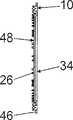
图4:图3中轮毂的侧视图,及Figure 4: Side view of the hub in Figure 3, and
图5:图3中轮毂的一个变型。Figure 5: A variant of the hub in Figure 3.
具体实施方式Detailed ways
图1表示一个角磨机36的俯视图,它具有一个支承在壳体38中的、未示出的电动机。该角磨机36可通过第一手把40及第二手把44操作,第一手把在背离插接式刀具的一侧上与壳体38构成一体并纵向延伸,第二手把在插接式刀具的区域中被固定在一个变速器壳体42上并垂直于纵向地延伸。FIG. 1 shows a plan view of an
图2表示在卸下状态中的插接式刀具。该插接式刀具设有一个由钢板作的、可被旋转驱动的盘形轮毂10,在它的径向外部区域上可固定一个构成磨削盘的磨料14。该磨料14基本上由玻璃纤维垫、磨料及粘接剂组成,它们彼此被压制成一个硬的盘,其中粘接剂在一个热处理工序中被硬化。FIG. 2 shows the plug-in tool in the removed state. The plug-in tool is provided with a rotatably driven disk-
轮毂10被作成在径向上具有变化的抗弯刚度,其中为了适配抗弯刚度,轮毂10的径向外部区域被缝槽式槽16有目的地削弱。槽16被作成径向地向外敞开,由此有利地形成了可尽可能彼此无关地偏移的扇段。槽16具有一个恒定的宽度及在径向上向内一直延伸到一个区域的紧前面,在这一区域中开有孔30,32,这些孔用于通过一个快速夹紧系统使插接式刀具固定到角磨机的主轴上。在轮毂10的中心区域中开有一个圆形孔28,用于插接式刀具的对中。The
轮毂10在两侧上被磨料14的至少一个层22,24覆盖,其中在朝着角磨机36的一侧48上,磨料14基本上用其整个厚度安置在一个环形凹部中,由此轮毂10及磨料14有利地在向角磨机36的方向上终止在一个共同的平面中。在工作中磨料14从轮毂10松下的情况下,该磨料14在背离角磨机36的方向上仍被轮毂10防失落地保持(图2及4)。在背离角磨机36的一侧34上,磨料14的一个由玻璃纤维垫构成的层22径向向内地覆盖着轮毂10。The
磨料14及轮毂10通过连接装置26在转动方向上形状锁合地连接(图4)。连接装置26由轴向上延伸的、成型在轮毂10上的凸起部分构成,它们穿过磨料14或插在其中。构成连接装置26的凸起部分与孔16,28,30,32在一个共同的冲压工序中被成形出。The abrasive material 14 and the
在磨料14的制造过程中,轮毂10及磨料14经受一个共同的热处理工序,其中在磨料14及轮毂10之间的材料接合的连接、确切地说粘接连接被固化。During the production of the abrasive material 14 , the
图5中表示一个变型的轮毂12。实质上相同的组成部分原则上用相同的标号表示。此外对于相同的特征及功能可参考对图2及3中实施例的说明。A modified
轮毂12具有槽18,20,它们被作成径向向外地敞开及在径向上具有不同的宽度。槽18被构造成T形及在径向内区域上具有比径向外区域上大的宽度;而槽20被构造成V形及径向向内地宽度减小。在图5中槽18及20彼此相组合,但也可设想,在轮毂上仅设置一种槽18或20。The
Claims (14)
Translated fromChineseApplications Claiming Priority (2)
| Application Number | Priority Date | Filing Date | Title |
|---|---|---|---|
| DE10106979.0 | 2001-02-15 | ||
| DE10106979ADE10106979A1 (en) | 2001-02-15 | 2001-02-15 | Tool with a rotating, disc-shaped hub |
Publications (2)
| Publication Number | Publication Date |
|---|---|
| CN1457285Atrue CN1457285A (en) | 2003-11-19 |
| CN100431794C CN100431794C (en) | 2008-11-12 |
Family
ID=7674100
Family Applications (1)
| Application Number | Title | Priority Date | Filing Date |
|---|---|---|---|
| CNB028003012AExpired - Fee RelatedCN100431794C (en) | 2001-02-15 | 2002-01-23 | Heavy-duty tool with rotationally driven disk-shaped hub |
Country Status (8)
| Country | Link |
|---|---|
| US (1) | US6902471B2 (en) |
| EP (1) | EP1361935B1 (en) |
| JP (1) | JP2004517749A (en) |
| KR (1) | KR20030014665A (en) |
| CN (1) | CN100431794C (en) |
| DE (2) | DE10106979A1 (en) |
| MY (1) | MY133293A (en) |
| WO (1) | WO2002064316A1 (en) |
Families Citing this family (23)
| Publication number | Priority date | Publication date | Assignee | Title |
|---|---|---|---|---|
| DE10218196B4 (en)* | 2002-04-24 | 2017-06-29 | Robert Bosch Gmbh | Insert tool and quick-release system with a rotating drivable, hub-shaped hub |
| DE10360252A1 (en)* | 2003-12-20 | 2005-07-21 | Robert Bosch Gmbh | tool adapter |
| DE10360246A1 (en)* | 2003-12-20 | 2005-07-28 | Robert Bosch Gmbh | Insert tool for a machine tool |
| USD526553S1 (en)* | 2004-09-21 | 2006-08-15 | Ehwa Diamond Industrial Co., Ltd. | Metal-cutting saw blade |
| USD564321S1 (en)* | 2006-04-12 | 2008-03-18 | Professional Tool Products, Llc | Portion of a housing for a rotary tool |
| USD619152S1 (en) | 2009-12-18 | 2010-07-06 | Techtronic Power Tools Technology Limited | Adapter |
| USD623034S1 (en) | 2009-12-18 | 2010-09-07 | Techtronic Power Tools Technology Limited | Tool arbor |
| USD653523S1 (en) | 2010-09-29 | 2012-02-07 | Milwaukee Electric Tool Corporation | Adapter for a tool |
| USD651062S1 (en) | 2010-09-29 | 2011-12-27 | Milwaukee Electric Tool Corporation | Tool interface for an accessory |
| USD646542S1 (en) | 2010-09-29 | 2011-10-11 | Milwaukee Electric Tool Corporation | Accessory interface for a tool |
| USD651876S1 (en) | 2010-12-14 | 2012-01-10 | Techtronic Power Tools Technology Limited | Universal interface for accessory blades |
| USD651877S1 (en) | 2010-12-14 | 2012-01-10 | Techtronic Power Tools Technology Limited | Universal interface for accessory blades |
| USD652274S1 (en) | 2010-12-14 | 2012-01-17 | Techtronic Power Tools Technology Limited | Universal interface for accessory blades |
| USD651875S1 (en) | 2010-12-14 | 2012-01-10 | Techtronic Power Tools Technology Limited | Universal interface for accessory blades |
| USD651874S1 (en) | 2010-12-14 | 2012-01-10 | Techtronic Power Tools Technology Limited | Universal interface for accessory blades |
| USD651878S1 (en) | 2010-12-14 | 2012-01-10 | Techtronic Power Tools Technology Limited | Universal interface for accessory blades |
| USD694596S1 (en) | 2012-06-25 | 2013-12-03 | Techtronic Power Tools Technology Limited | Universal interface for accessory blades |
| USD694598S1 (en) | 2012-06-25 | 2013-12-03 | Techtronic Power Tools Technology Limited | Universal interface for accessory blades |
| USD694076S1 (en) | 2012-06-25 | 2013-11-26 | Techtronic Power Tools Technology Limited | Universal interface for accessory blades |
| USD694597S1 (en) | 2012-06-25 | 2013-12-03 | Techtronic Power Tools Technology Limited | Universal interface for accessory blades |
| USD694599S1 (en) | 2012-06-25 | 2013-12-03 | Techtronic Power Tools Technology Limited | Universal interface for accessory blades |
| US9555554B2 (en) | 2013-05-06 | 2017-01-31 | Milwaukee Electric Tool Corporation | Oscillating multi-tool system |
| USD717086S1 (en)* | 2014-04-28 | 2014-11-11 | Pendleton Safe Company, Inc. | Shelf |
Family Cites Families (27)
| Publication number | Priority date | Publication date | Assignee | Title |
|---|---|---|---|---|
| US2278301A (en)* | 1941-02-12 | 1942-03-31 | Abrasive Company | Grinding wheel |
| US2652321A (en)* | 1950-09-07 | 1953-09-15 | Norton Co | Grinding wheel |
| US2805530A (en)* | 1955-06-30 | 1957-09-10 | Schaffner Mfg Company Inc | Finishing apparatus |
| US2882139A (en)* | 1957-02-12 | 1959-04-14 | F L & J C Codman Company | Process of manufacture of buffing elements |
| US3191208A (en)* | 1962-04-19 | 1965-06-29 | George R Churchill Company Inc | Buffing wheel |
| US3353306A (en)* | 1964-01-31 | 1967-11-21 | Norton Co | Hub mounting for grinding wheels |
| US3362114A (en)* | 1964-11-04 | 1968-01-09 | Rexall Drug Chemical | Universal driving spindle and wheel assembly |
| US3500592A (en)* | 1968-01-09 | 1970-03-17 | Robert A Harrist | Plastic hub and the application thereof to an abrasive wheel |
| US3667169A (en)* | 1970-04-27 | 1972-06-06 | Norton Co | Abrasive finishing article |
| DE2324616A1 (en)* | 1972-05-17 | 1973-12-06 | S P A M | GRINDING TOOLS |
| US3793783A (en)* | 1972-10-02 | 1974-02-26 | Norton Co | Segmental cut-off grinding wheel |
| US3795078A (en)* | 1972-11-01 | 1974-03-05 | Norton Co | Segmental cut-off wheel |
| US3795077A (en)* | 1972-12-04 | 1974-03-05 | Norton Co | Segmental cut-off grinding wheel |
| US4177611A (en)* | 1978-05-24 | 1979-12-11 | Carr Rollett Derrick | Sanding and buffing attachment for power tools |
| US4251955A (en)* | 1979-01-29 | 1981-02-24 | The Warner & Swasey Company | Hub assembly |
| IT1145270B (en)* | 1979-07-09 | 1986-11-05 | Merit Abrasive Prod | IMPROVEMENT IN ABRASIVE DISCS |
| DE3112773A1 (en)* | 1981-03-31 | 1982-10-07 | Manfred 5860 Iserlohn Siebel | Device for clamping polishing wheels on the drive spindle of a polishing machine |
| US4541205A (en)* | 1983-04-08 | 1985-09-17 | United Abrasives, Inc. | Abrasive wheel assembly |
| US4850158A (en)* | 1987-10-09 | 1989-07-25 | Schaffner William M | Method of making buffing wheel |
| US5138735A (en)* | 1991-03-18 | 1992-08-18 | Safety-Kleen Corporation | Buffing pad and attachment system therefor |
| DE4236964A1 (en)* | 1992-11-02 | 1994-05-05 | Hilti Ag | Disc-shaped tool for angle grinders |
| DE4430229A1 (en) | 1994-08-25 | 1996-02-29 | Eisenblaetter Gerd Gmbh | Overlapping leaf abrasive disc esp. for attachment to grinder or sander |
| DE4432168A1 (en)* | 1994-09-09 | 1996-03-14 | Rueggeberg August | Flap grinding wheel |
| US5806132A (en)* | 1995-05-23 | 1998-09-15 | The Malish Corporation | Locking coupler for floor maintenance pad |
| JPH1199460A (en)* | 1997-09-29 | 1999-04-13 | Yanase Kk | Rotary polishing tool |
| ATE219410T1 (en)* | 1997-10-16 | 2002-07-15 | Rueggeberg August Gmbh & Co | GRINDING DISC |
| US6136143A (en) | 1998-02-23 | 2000-10-24 | 3M Innovative Properties Company | Surface treating article including a hub |
- 2001
- 2001-02-15DEDE10106979Apatent/DE10106979A1/ennot_activeCeased
- 2002
- 2002-01-23DEDE50211041Tpatent/DE50211041D1/ennot_activeExpired - Lifetime
- 2002-01-23WOPCT/DE2002/000202patent/WO2002064316A1/enactiveIP Right Grant
- 2002-01-23EPEP02704602Apatent/EP1361935B1/ennot_activeExpired - Lifetime
- 2002-01-23USUS10/257,349patent/US6902471B2/ennot_activeExpired - Lifetime
- 2002-01-23JPJP2002564090Apatent/JP2004517749A/enactivePending
- 2002-01-23KRKR1020027013561Apatent/KR20030014665A/ennot_activeWithdrawn
- 2002-01-23CNCNB028003012Apatent/CN100431794C/ennot_activeExpired - Fee Related
- 2002-02-11MYMYPI20020475Apatent/MY133293A/enunknown
Also Published As
| Publication number | Publication date |
|---|---|
| KR20030014665A (en) | 2003-02-19 |
| JP2004517749A (en) | 2004-06-17 |
| MY133293A (en) | 2007-11-30 |
| WO2002064316A1 (en) | 2002-08-22 |
| EP1361935A1 (en) | 2003-11-19 |
| DE50211041D1 (en) | 2007-11-22 |
| US20030176153A1 (en) | 2003-09-18 |
| CN100431794C (en) | 2008-11-12 |
| DE10106979A1 (en) | 2002-09-05 |
| EP1361935B1 (en) | 2007-10-10 |
| US6902471B2 (en) | 2005-06-07 |
Similar Documents
| Publication | Publication Date | Title |
|---|---|---|
| CN1457285A (en) | Heavy-duty tool with rotationally driven disk-shaped hub | |
| JP2004518549A (en) | Mounting tool with a disc-shaped hub that can be driven to rotate | |
| EP2345506A2 (en) | An abrasive wheel comprising a fan-like structure | |
| JP4358840B2 (en) | A saw blade with multiple bore sizes | |
| CN100506489C (en) | Attachment and rapid-chucking system, comprising a rotary driven, disc-shaped hub | |
| US6526959B1 (en) | Adhesive sheet for noise and shock absorption, and saw blade making use of it, and manufacturing methods therefor | |
| CN106457520B (en) | Fiber board grinding tool | |
| US7497766B2 (en) | Tool-holding device for an insert tool with at least essentially disk-shaped hub | |
| US6066034A (en) | V-shaped flap disc abrasive tool | |
| KR19990062810A (en) | Cutting device and its manufacturing method | |
| JP2009528174A (en) | Grinding disc and grinding wheel for holding the same | |
| JP4796540B2 (en) | Rotary tool for surface machining | |
| US20020123302A1 (en) | Cutting and grinding wheel for a rotary tool | |
| CA2690596A1 (en) | An abrasive wheel comprising a fan-like structure | |
| JPS60114470A (en) | Rotary grinding/polishing tool | |
| CN213351061U (en) | Multi-piece composite saw blade with polished cutting surface | |
| US7739932B2 (en) | Tool-holding device | |
| KR200311544Y1 (en) | Cutter for stone processing | |
| KR100430676B1 (en) | Method for bonding a steel shank and copper plate of no noise cutter | |
| KR200270828Y1 (en) | Cutter for stone | |
| JP7450864B1 (en) | Metal saw with side blade and manufacturing method and processing method of metal saw with side blade | |
| KR200193826Y1 (en) | A grinding wheel for grinding machine | |
| US20250170687A1 (en) | Secure grinder blade and tapered tool-side locking hub for flush cutting concrete | |
| JP3296981B2 (en) | Super abrasive wheel with resin laminated core | |
| JPS63191573A (en) | Cutting grinding wheel reinforced with perforated metallic sheet |
Legal Events
| Date | Code | Title | Description |
|---|---|---|---|
| C06 | Publication | ||
| PB01 | Publication | ||
| C10 | Entry into substantive examination | ||
| SE01 | Entry into force of request for substantive examination | ||
| C14 | Grant of patent or utility model | ||
| GR01 | Patent grant | ||
| CF01 | Termination of patent right due to non-payment of annual fee | Granted publication date:20081112 Termination date:20210123 | |
| CF01 | Termination of patent right due to non-payment of annual fee |