CN1446323A - glasses holder - Google Patents
glasses holderDownload PDFInfo
- Publication number
- CN1446323A CN1446323ACN01813889.6ACN01813889ACN1446323ACN 1446323 ACN1446323 ACN 1446323ACN 01813889 ACN01813889 ACN 01813889ACN 1446323 ACN1446323 ACN 1446323A
- Authority
- CN
- China
- Prior art keywords
- inches
- supporting
- glasses
- mirror holder
- wearer
- Prior art date
- Legal status (The legal status is an assumption and is not a legal conclusion. Google has not performed a legal analysis and makes no representation as to the accuracy of the status listed.)
- Granted
Links
Images

Classifications
- G—PHYSICS
- G02—OPTICS
- G02B—OPTICAL ELEMENTS, SYSTEMS OR APPARATUS
- G02B27/00—Optical systems or apparatus not provided for by any of the groups G02B1/00 - G02B26/00, G02B30/00
- G02B27/01—Head-up displays
- G02B27/017—Head mounted
- G02B27/0176—Head mounted characterised by mechanical features
- G—PHYSICS
- G02—OPTICS
- G02C—SPECTACLES; SUNGLASSES OR GOGGLES INSOFAR AS THEY HAVE THE SAME FEATURES AS SPECTACLES; CONTACT LENSES
- G02C11/00—Non-optical adjuncts; Attachment thereof
- G02C11/10—Electronic devices other than hearing aids
- G—PHYSICS
- G02—OPTICS
- G02C—SPECTACLES; SUNGLASSES OR GOGGLES INSOFAR AS THEY HAVE THE SAME FEATURES AS SPECTACLES; CONTACT LENSES
- G02C3/00—Special supporting arrangements for lens assemblies or monocles
- G02C3/003—Arrangements for fitting and securing to the head in the position of use
Landscapes
- Physics & Mathematics (AREA)
- General Physics & Mathematics (AREA)
- Optics & Photonics (AREA)
- Health & Medical Sciences (AREA)
- Ophthalmology & Optometry (AREA)
- Acoustics & Sound (AREA)
- General Health & Medical Sciences (AREA)
- Otolaryngology (AREA)
- Eyeglasses (AREA)
Abstract
Description
Translated fromChinese技术领域technical field
本发明总的涉及一种在头上的保持装置以避免与头的横向侧面相接触,同时保持眼镜处在佩戴者的视野内和/或提供一用于支承任何各类可携带的电子装置的平台。The present invention generally relates to a retaining device on the head to avoid contact with the lateral sides of the head while maintaining eyeglasses within the wearer's field of view and/or providing a support for any type of portable electronic device platform.
背景技术Background technique
近年来在眼镜领域内已有非常多类型的改进,特别是关于希望用在剧烈运动中的眼镜或如时髦的太阳镜。例如一些改进已组合在具有一整体镜片的眼镜中例如Blades结构型(Oakley,lnc.),M Frame型,(Dakley,lnc.)和Zere型,也是由Oakley,lnc.制造的。这些眼镜结构型式实现了多种功能优点,例如最大地遮挡了周边光,减小了光学图象畸变和提高了戴者的舒适水平,从而优于先前的剧烈运动眼镜。In recent years there have been many types of improvements in the field of spectacles, especially with regard to spectacles intended for vigorous sports or eg stylish sunglasses. For example, improvements have been incorporated in spectacles having an integral lens such as theBlades® construction type (Oakley, inc.), the MFrame® type, (Dakley, inc.) and theZere® type, also manufactured by Oakley, inc. These eyewear configurations achieve multiple functional advantages, such as maximum peripheral light shielding, reduced optical image distortion, and increased wearer comfort levels, over previous strenuous sports eyeglasses.
镜片几何形状也是各种改进的技术主题。该Blades眼镜的这种整体镜片结合了例如在授予Jannard的美国专利No.4,859,048中揭示的圆片(柱式)几何形状。这种几何形状允许该镜片紧紧地符合于戴者的脸面并遮挡直接来自戴者的正对前面(前面方向)和周边(横向方向)的光、风、灰尘等。也可参见授予Jannard的美国专利No4,867,550的专利文献。Lens geometry is also the technical subject of various improvements. The integral lens of the Blades(R) eyeglass incorporates a disc (cylindrical) geometry such as that disclosed in US Patent No. 4,859,048 to Jannard. This geometry allows the lens to conform tightly to the wearer's face and block light, wind, dust, etc. from directly in front of the wearer (frontal direction) and peripheral (lateral direction). See also the patent literature of US Patent No. 4,867,550 to Jannard.
通过例如这些所有属于Houston等人的美国专利No.5,648,832;5,689,323;5,969,789和6,010,218中揭示的技术已实现了许多精密地对由于扫视(或广角的倾斜)和环顾以及其他光学物体引起的分光移位(prismatic shift)的控制措施。Many finely tuned spectral shifts due to saccade (or wide angle tilt) and look around and other optical objects have been achieved by techniques such as those disclosed in U.S. Patent Nos. 5,648,832; 5,689,323; (prismatic shift) control measures.
近年来也做了许多在眼镜保持装置方面的改进。例如参见Jannard等人的美国专利No.5,137,342(用于双耳撑装置的管状牵拉装置);Jannard的No.5,249,001(适于提供一个通过各种头宽度指向中间偏压的耳撑和镜架);Jannard等人的No.5,760,868(整体无铰链眼镜框)和Houston等人的No.5,805,261(有偏压的眼镜框)。Many improvements in eyeglass retention devices have also been made in recent years. See, for example, U.S. Patent No. 5,137,342 to Jannard et al. (tubular puller for double ear support devices); ); No. 5,760,868 to Jannard et al. (integral hingeless spectacle frames) and No. 5,805,261 to Houston et al. (biased spectacle frames).
所有这些上述的保持装置的改进一般涉及双耳撑结构方案,其中,耳撑或边撑是向后沿着佩戴者的头部延伸的以实现眼镜的保持状态。虽然有这些改进,但仍需要新的眼镜保持方案以能消除在边撑上的侧向压力而且还能提供舒适的眼镜保持作用。All of these above-mentioned retention device improvements generally involve a double ear support arrangement, wherein the ear support or the temple is extended rearwardly along the wearer's head to achieve the holding position of the eyeglasses. Despite these improvements, there remains a need for new eyeglass retention solutions that eliminate lateral pressure on the temples and yet provide comfortable eyeglass retention.
另外,仍有对这样保持装置的需求,即它能够支承和分布来自附加到本保持装置上的载荷重量,例如眼镜镜片,无线通讯装置,头戴显示器电子线路和任何各种其他音频的和/或视频的电子部件。Additionally, there remains a need for a holding device that is capable of supporting and distributing weight from loads attached to the holding device, such as eyeglass lenses, wireless communication devices, head-mounted display electronics, and any of various other audio and/or or video electronics.
发明内容Contents of the invention
按照本发明的一个方面,提供一个眼镜保持装置。该装置包括一眼镜支承其具有一长弧形的镜架。该镜架包括一前边端部和一枕骨端部,它们的尺寸构造成从一佩戴者的脸面延伸横跨该佩戴者的头顶直到该头的后部例如在外部枕骨隆凸的附近。该支承包括一第一部件和一第二部件,它们在前面区域中连接一起并分开间置在前面区域和枕骨区域之间。According to one aspect of the present invention, an eyeglass retaining device is provided. The device includes a frame for supporting glasses having an elongated arc. The frame includes an anterior end and an occipital end sized to extend from a wearer's face across the top of the wearer's head to the back of the head, such as in the vicinity of the outer occipital eminence. The support includes a first part and a second part, which are connected together in the front region and spaced apart between the front region and the occipital region.
该第一和第二部件的至少一部分横向地分开间置一在从约1/2英寸到约6英寸的范围内的距离。作为优选,该第一和第二部件的至少一部分横向地分开一在从约1.5英寸到约3英寸的范围内的距离。在有些实施例中,在第一和第二部件之间的最大间距是在从约2英寸到3英寸的范围内,最好是在沿着头顶的一位置上。At least a portion of the first and second members are laterally spaced apart a distance in the range of from about 1/2 inch to about 6 inches. Preferably, at least a portion of the first and second members are laterally separated by a distance in the range of from about 1.5 inches to about 3 inches. In some embodiments, the maximum spacing between the first and second members is in the range of from about 2 inches to 3 inches, preferably at a location along the crown of the head.
作为优选,至少一镜片设置在镜架的前面端部上。作为变型,设置两个镜片。该支承的前面端部可直接地连接到该镜片边框上或连接到该位于一包含右和左边框的镜架上的鼻梁架上。Preferably, at least one lens is arranged on the front end of the frame. As a variant, two mirrors are provided. The front end of the support may be attached directly to the lens rim or to the bridge on a frame comprising right and left rims.
该镜架具有一从前端到枕骨端的弧形长度,其足以从该镜片或边框延伸到占有希望市场份额的普通佩戴者的外部枕骨隆凸附近(例如成年男性,成年女性,儿童,亚洲人,欧洲人等)。这种从前端到枕骨端的弧形长度一般在从约8英寸到18英寸的范围内,并在大多数成年人具体例子中,在从约14英寸到约16英寸的范围内。The frame has an arcuate length from the front end to the occipital end sufficient to extend from the lens or rim to near the outer occipital prominence of the average wearer with a desired market share (e.g. adult male, adult female, child, Asian, Europeans, etc.). The length of this arc from the front end to the occiput end generally ranges from about 8 inches to 18 inches, and in most adult human embodiments, from about 14 inches to about 16 inches.
作为优选,该第一和第二部件在枕骨端上或其前面连接一起。该镜架的枕骨端可以另外设有一其中含有电子器件的壳体。考虑到的电子器件包括数字或其他存储装置,接收器,发射器,头戴显示器驱动电路,动力源和相关部件。Preferably, the first and second parts are joined together at or in front of the occipital end. The occipital end of the frame may additionally be provided with a housing containing the electronics therein. Electronics considered include digital or other storage devices, receivers, transmitters, head mounted display drive circuits, power sources and related components.
在一实施例中,该镜架还包括一用于静置在一佩戴者鼻子上的鼻托。该鼻托可以和边框一体地形成,或可以作为一单独形成的鼻件连接设置。In one embodiment, the frame further includes a nose pad for resting on a wearer's nose. The nose pads can be integrally formed with the frame, or can be connected as a separately formed nose piece.
一般地,该弧形镜架从前面端部向后地延伸贯穿大于约180度的弧形结构。一参考点可标定在镜架内侧表面上距鼻托中点最大直线距离上。该镜架最好沿着超过参考点至少约2英寸的弧形结构延伸到该枕骨端。一般地,该镜架沿着具有从超过参考点约2英寸到约6英寸的范围内的长度的弧形结构延伸。Typically, the curved frame extends rearwardly from the front end through a curved structure greater than about 180 degrees. A reference point can be calibrated on the maximum linear distance from the inner surface of the frame to the midpoint of the nose pad. The frame preferably extends to the occipital end along an arc at least about 2 inches beyond the reference point. Generally, the frame extends along an arcuate structure having a length ranging from about 2 inches to about 6 inches beyond a reference point.
在鼻托上的中点和镜架枕骨端之间的直线距离当该镜架处在松弛构型时最好是至少约3英寸。一般地,在鼻托上中点和镜架枕骨端之间的该直线距离在从约5英寸到约8英寸的范围内。该镜架的枕骨端部最好定位在位于一通过参考点的后切线前面的从约1.5英寸到约3.5英寸的范围内。Preferably, the linear distance between the midpoint on the nose pads and the occipital end of the frame is at least about 3 inches when the frame is in the relaxed configuration. Generally, this linear distance between the upper midpoint of the nose pads and the occipital end of the frame is in the range of from about 5 inches to about 8 inches. The occipital end of the frame is preferably positioned within a range from about 1.5 inches to about 3.5 inches forward of a posterior tangent passing through the reference point.
按照本发明的其他方面,提供一种将至少一镜片稳定在佩戴人视野中的方法。该方法包括步骤如下:提供一眼镜,其具有一用于向后延伸横跨一佩戴者头顶的弧形镜架;将该镜架置于该佩戴者的头上,然后通过将横向分开间置的一第一和一第二支承沿着该佩戴者头顶的至少一部分上安置而使之稳定。According to other aspects of the invention, a method of stabilizing at least one lens in the field of view of a wearer is provided. The method comprises the steps of: providing spectacles having a curved frame for extending rearwardly across the top of a wearer's head; A first and a second support are positioned along at least a portion of the crown of the wearer's head to stabilize it.
作为优选,该第一和第二支承横向地分开间隔在从约1/2英寸到约6英寸范围内的距离。该第一和第二支承的每个的宽度在从约0.002英寸到约3英寸的范围内。Preferably, the first and second supports are laterally spaced apart by a distance in the range of from about 1/2 inch to about 6 inches. The width of each of the first and second supports ranges from about 0.002 inches to about 3 inches.
按照随后优选实施例的详细描述,并结合附图和权利要求书考虑,本发明另外特征和优点对于本领域熟练技术人员来说将变得显而易见。Additional features and advantages of the present invention will become apparent to those skilled in the art from the ensuing detailed description of the preferred embodiments, considered in conjunction with the accompanying drawings and claims.
附图说明Description of drawings
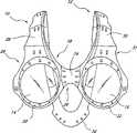
图1是一本发明眼镜保持装置实施例的前正示意图;Fig. 1 is a front schematic view of an embodiment of a glasses holding device of the present invention;
图2是图1的眼镜保持装置的一顶视平面图;Figure 2 is a top plan view of the eyeglass holder of Figure 1;
图3是图1的眼镜保持装置的侧正视图;Figure 3 is a side elevational view of the eyeglass holder of Figure 1;
图4是表明另一可选择结构的如图2所示的顶视平面图。Figure 4 is a top plan view of that shown in Figure 2 illustrating an alternative structure.
具体实施方式Detailed ways
参看图1,其中表示了本发明一包括保持装置12的眼镜10实施例的前正视图。虽然本发明眼镜保持装置下面首先将在双镜片眼镜例如太阳镜、无色透明眼镜的双镜片眼镜中阐述,但本发明可广泛地应用到众多变型的眼镜中,包括一体镜片的眼镜,防护性眼镜或遮光眼罩,电子头顶显示器,或其他按照本文公开内容的观点对于本领域的技术人员来说将是明显的各种产品。Referring to Figure 1, there is shown a front elevational view of an embodiment of
该支承装置12适合于支承任何各种便携式的电子电路或装置,它们在以前由于体积尺寸,重量或其他考虑很难组合在传统的眼镜保持装置中。而本发明镜架12的这种跨过头的结构方案则允许载荷横过该佩戴者头部的分布,以及使相对体积大或沉重的电子器件沿着该支承装置12的长度上定位或者在该支承装置12的例如在枕骨端部34处后面方位上定位。这样就能实现该眼镜保持装置10以流线型的样式承载电子装置,且位于佩戴者的视野之外,同时使重量横过佩戴者头部地分布,因此该眼镜不会导致在其负荷下移位,并且令人不舒服的压力也不会落在佩载者的鼻子、耳朵上或颞部区域上。The
在本发明者所考虑的电子器件中有数字式或其他存储装置和恢复电路例如为了从MP3格式存储器或其他存储器装置再现音乐或其他信息。作为选择,任何各种各样的例如用于音乐,通讯和全球定位的接收机和/或发送机也都可以通过本支承装置12来携带。用于驱动例如液晶显示器或其他小型的显示技术的头戴显示器的驱动器和其他电子装置也可通过支承12携带。通过该支承12还可另外地携带可更换的或可再充电的供电装置和其他电子器件或机械的部件。Among the electronic devices contemplated by the present inventors are digital or other storage means and recovery circuits eg for reproducing music or other information from MP3 format memory or other storage means. Alternatively, any of a variety of receivers and/or transmitters such as those used for music, communication and global positioning can also be carried by the
本发明支承装置12也可以仅仅用于支承任何上述的或其他电子部件或装置,而不用支承在佩戴者视野中的一个或多个镜片。于是,在本文揭示的支承装置12任何实施例中,该镜片边框就可以省去这按照本文公开内容观点对于本领域的技术人员来说是显而易见的。The
在图1中描述绘的眼镜10包括一支承2,其形式为一长弧形弯曲镜架具有一用于定位在佩戴者头部的前面的前端和具有一用于定位在佩戴人头部的后侧面上的枕骨的或后面的端部。在一个实施方案中该支承12延伸通过一弧形结构,该弧形尺寸构造成从鼻子上方的眉间区域一般横跨戴者头顶地延伸到头后部的该外部枕骨隆凸部。The
该支承12从前端到枕骨端的该弧形长度通常在从约8英寸到约18英寸的范围内,而且一般在从约14英寸到约16英寸的范围内以适合于大多数成年人的头部。本文公开的特定尺寸是用于参考的目的,而且任何各种其他特定的尺寸都可以选用以将一具体的商业产品优化来适应所希望的群体。例如可以生产不同尺寸的产品对应于各平均尺码以用于成年男性,成年女性和各种年龄儿童或青少年。另外,成年男性和女性的尺码对于不同的亚洲人,欧洲人和其他销售群体还可以有区别,这是对本领域的技术人员容易理解的。The arc length of the
该支承12最好包括一第一支承部件28和一第二支承部件30并构造得横跨该戴者头的顶部延伸到枕骨端34。一般地,该第一和第二支承部件28和30的后面端部连接在或约在该枕骨端34处,其可以接合在该外部枕骨隆凸上。该第一支承部件28和第二支承部件30的前面端部29、31既可以直接在一起或者通过该眼镜的一部分连接一起,这将在下面描述。The
一般地,第一和第二支承部件28和30按要求具有一足够的弹性或记忆性,以使它们可铰接或弹性变形地装戴到佩戴者的头上并保持一朝向它们原抬构型方向的偏压力从而实现牢固地佩戴在头上。该支承12另外方面的功能要求将在以后描述。Generally, the first and
至少该第一和第二支承部件28和30的接触头的表面横向地沿着该支承12弧形长度的至少一部分上相互间隔分开以给予该眼镜10侧向的稳定性。在第一支承部件28和第二支承部件30之间的这种横向间隔是至少位于从约1/2英寸到约6英寸范围内的某点上,作为优选,该横向间隔在从约1.5英寸到约4英寸的范围内。在某些实施例中,该间隔在沿着头顶的至少某点上在约2英寸和约3英寸之间。At least the contact surfaces of the first and
该第一支承部件28和第二支承部件30每个的宽度可以显著地改变,这取决于通过支承12所希望携带的载荷以及美观的因素。例如在按照本发明适于携带相对轻负载的一种丝框实施方案中(例如只承载轻重量或没有电子部件),该第一和第二支承28和30每个可以由丝材或条带材制造,其具有一在从约0.020英寸到约0.25英寸或更大的范围内的宽度。模制的或挤压成型的聚合物部件可具有一在从约0.125英寸到约4英寸或更大的范围内的宽度。作为优选,一模制的或挤压成型的第一或第二支承部件28或30具有一在从约0.25英寸到约1.5英寸并最好从约0.25英寸到约0.75英寸的范围内的宽度,当然为了沿着支承12包围电子器件而要求一更大宽度的情况除外。The width of each of the
在图3所示的实施例中,该第一和第二支承部件28和30基本相互平行地从佩戴者头的前面延伸到后面。该第一和第二支承部件28和30也可以是彼此相互倾斜的要么使得它们居中地在一向后的方向上倾斜从而该间隔在前面端部处大于该后面端部的间隔,或者它们在朝后面的方向上横向地倾斜使得它们在后面端比前面端部具有一更大的间隔。这个后述的构造可有效地用在如图4所示的支承12连接在眼镜框的例如在鼻梁架24的中间部分上的实施例中。In the embodiment shown in FIG. 3, the first and
在第一和第二支承部件28和30之间的该间隔的长度在本表示的实施例中在从前面到后面的所有路程上或整个头部上延伸。这个长度可以从前面到后面显著缩短。该间隔的前至后的长度一般可以超过该眼镜总的前后尺寸的20%,而且,最好超过该眼镜总的前后尺寸的50%以最佳化本发明的稳定特性。该最大间隔的位置最好在该佩戴者头的顶部,最好定中心在前和后之间的中间部位上或相对于眼镜前和后之间的中点稍稍往前一点处。The length of the distance between the first and the
在图4描述的一实施例中,该第一和第二支承部件28和30约在佩戴者额顶处连接在一起并且一单独延伸部分33向下延伸以横过佩戴者的额部用于连接到一镜架18的鼻梁架区域24上。还可以设计任何其他各种实现本发明载荷分布和平衡的结构方案。In one embodiment depicted in FIG. 4, the first and
该眼镜10优选地支承至少一位于佩戴者视野中的镜片。在本示出的实施例中,该支承12承载一第一镜片14和一第二镜片16。第一镜片14支承在一第一边框20中,而第二镜片16支承在一第二边框22中。在本示出的实施例中,该第一和第二边框20和22通过一鼻梁架24相连接,它们一起形成一镜架18。鼻梁架24与第一和第二边框20、22相组合而形成一鼻位开口26。鼻位开口26可以设有一体形成的鼻托或可拆卸的鼻梁架或鼻托这按照本文揭示的观点对于该领域的技术人员是显而易见的。The
该支承12可以任何方式连接到镜架18上。在本表示的实施例中,该第一部件28连接到第二边框20上和第二支承部件30连接到第二边框22上。参见图1和2,作为优选,该第一和第二支承部件28及30可连接到鼻梁架24上。在其他实施例中,该第一和第二支承部件28和30一起合并成一单个元件33,其延伸以横过眉间区域和额部的至少一部分,然后连接到鼻梁架24上或镜架18的其他部分上,见图4。The
参见图30,其中表示了图1眼镜10的一侧正视图。如从中看到的,该第一和第二支承部件28和30向下和向前凹入地通过一长形弧结构(如所呈现的)以适合于在枕骨端部34接合该外部的枕骨隆凸;并且延伸横跨该佩戴者头的顶部以支承在佩戴者视野前边的镜架18。一水平参考线36表示成在一位于鼻托40之机械中心上的第一接触点38和一位于支承12内表面上并在离开第一接触点38为最大直线距离上的第二接触点42之间延伸。虽然该参考线36为了方便被定义为“水平”,但它没有必要与真实水平有关。Referring to Fig. 30, there is shown a side elevational view of the
位于第一接触点38和第二接触点42之间的松弛时的直线距离一般在从约5英寸或对于小尺寸或高弹性结构为更小些到约8英寸的范围内。在一实施例中该在第一接触点38和第二接触点42之间的直线距离在从约7英寸到英寸的范围内。The relaxed linear distance between the first contact point 38 and the second contact point 42 generally ranges from about 5 inches or less for small size or highly resilient structures to about 8 inches. In one embodiment the linear distance between the first contact point 38 and the second contact point 42 is from about 7 inches to in the range of inches.
一后切线46表示成在支承12的内侧面上通过第二接触点42。一枕骨切线48平行后切线46地延伸并通过枕骨端34。枕骨切线48与水平参考线36形成交叉50。A back tangent 46 is shown passing through the second contact point 42 on the inner side of the
一般地,沿着水平参考线36在枕骨切线48和后切线46之间的直线距离大于约0.5或1英寸并且作为优选在从约
在交点50和枕骨端部34之间的直线距离一般在从约英寸到约4英寸的范围内,并且优选为在从约
从第一接触点38到枕骨端部34在松弛结构时的直线距离一般在从约3英寸到约8英寸的范围内并且典型地在从约5英寸到约7英寸的范围内以适于一成年人。总体上,在第接触点38和枕骨端部34之间的静止距离可以显著变化,这取决于枕骨端34相对于镜架18的移动范围以及支承12的弹性或记忆程度。The linear distance from the first contact point 38 to the
作为优选,支承12可在一广大范围上柔性变形以适应一范围很广的头形尺寸,并且仍然在朝其原始构型的方向上保持一偏压从而在佩戴人的头上提供一保持偏压。该支承12的弹性可以从该第一和第二部件28和30的材料及横截面厚度和结构来实现。作为选择,该第一和第二支承部件28和30可设有一个或多个例如一延伸其中的弹簧丝或条带的弹簧元件以增加该支承12上的接合偏压。任何各种各样的弹簧材料都可定位在第一和第二部件28和30上或其内例如弹簧钢,Nitinol,或其他通过本领域的技术人员借助常规经验可选用的材料。Preferably, the
也可以沿着支承12的长度上设置一个或多个偏压的例如弹簧加载的铰链的铰链以在支承12的枕骨端部34上提供一个径向朝向指向的偏压。参见例如在申请人Houston等人美国专利号No.5,805,261中揭示的偏压铰链,其公开内容结合于此作参考。其中一可压缩的材料定位在两个相邻部件之间以偏压两个部件的定向定位。One or more biased hinges, such as spring loaded hinges, may also be provided along the length of the
该上述的支承12还可进一步改型以通过沿着支承12弧形长度上实现支承12的一个伸长而适于接纳一多种的头形尺寸。例如可以设置一个或多个连接结构52。其中,一第一部件54和一第二部件56可以相互相向地或相对离开地沿着支承12的弧结构移动。可以任何各种方式实现伸缩式连接结构,例如通过在两个相邻部件的一第一个上设置一凸出部分,其可滑动地接纳在该两个相邻部件的第二个上的对应孔中。该佩戴者可以调节支承12的两个相邻部件的相对位置以使佩戴最佳化。在两个例如54和56相邻部件之间的移动可以例如通过一摩擦装配阻止或通过任何各种的锁定结构。按此方式,该支承12的实际弧形长度可缩短或加长以实现眼镜10的调节从而使鼻托40适当地置于佩戴者的鼻子上并且枕骨端部34足够远地间置在支承12的弧形结构沿线上以提供有效地保持作用。The
该眼镜10可以用任何多种技术制造,这按照本文公开的观点对于本领域的技术人员来说可以理解的。例如,第一和第二支承部件28和30可以注射模制成它们最终要求的结构。该边框20和22和鼻梁架24(当采用时)可与第一和第二支承部件28和30模制为一体。作为优选,支承12可与镜架18分开地单独制成然后在一第二制造步骤时固定在一起。The
在一其中包含电子部件的实施例中,可以按希望在沿着镜架长度,镜片或边框的任何地方上设置另外功能的安装结构。例如耳机可以从一个或两个耳机支承件上指向佩戴者的耳朵,该耳机支承件可从眼镜的前面向后延伸,或从支承12的顶部向下延伸或从支承12的后部向前延伸。类似地,一个或多个麦克可以从一个或两个麦克风支承件指向佩戴者的嘴边,而麦克风支承件连接到所述镜架的边框或其他部分上。In an embodiment in which electronic components are incorporated, additional functional mounting structures may be provided anywhere along the length of the frame, lens or rim as desired. For example the earphones may be directed towards the wearer's ears from one or both earphone supports which may extend rearwardly from the front of the glasses, or downwardly from the top of the
虽然本发明已在特定优选实施例中作了说明,但是参照本文包含的公开内容对于本领域的熟练技术人员来说其他实施方案也将变得显而易见。因此,本发明的保护范围决不意味着通过揭示的实施例而受到局限,而是与所附权利要求书的全面保护范围相一致。While the invention has been described in terms of certain preferred embodiments, other embodiments will be apparent to those skilled in the art in view of the disclosure contained herein. Accordingly, the scope of the present invention is in no way intended to be limited by the disclosed embodiments, but is consistent with the full scope of the appended claims.
Claims (25)
Applications Claiming Priority (2)
| Application Number | Priority Date | Filing Date | Title |
|---|---|---|---|
| US09/585,593 | 2000-06-02 | ||
| US09/585,593US6325507B1 (en) | 2000-06-02 | 2000-06-02 | Eyewear retention system extending across the top of a wearer's head |
Related Child Applications (2)
| Application Number | Title | Priority Date | Filing Date |
|---|---|---|---|
| CN200610100589.8ADivisionCN1896805B (en) | 2000-06-02 | 2001-05-31 | Eyeglass with mp3 player |
| CN200510103887.8ADivisionCN100552497C (en) | 2000-06-02 | 2001-05-31 | Glasses capable of storing MP3 |
Publications (2)
| Publication Number | Publication Date |
|---|---|
| CN1446323Atrue CN1446323A (en) | 2003-10-01 |
| CN1227557C CN1227557C (en) | 2005-11-16 |
Family
ID=24342121
Family Applications (3)
| Application Number | Title | Priority Date | Filing Date |
|---|---|---|---|
| CN200610100589.8AExpired - Fee RelatedCN1896805B (en) | 2000-06-02 | 2001-05-31 | Eyeglass with mp3 player |
| CN200510103887.8AExpired - Fee RelatedCN100552497C (en) | 2000-06-02 | 2001-05-31 | Glasses capable of storing MP3 |
| CN01813889.6AExpired - Fee RelatedCN1227557C (en) | 2000-06-02 | 2001-05-31 | glasses holder |
Family Applications Before (2)
| Application Number | Title | Priority Date | Filing Date |
|---|---|---|---|
| CN200610100589.8AExpired - Fee RelatedCN1896805B (en) | 2000-06-02 | 2001-05-31 | Eyeglass with mp3 player |
| CN200510103887.8AExpired - Fee RelatedCN100552497C (en) | 2000-06-02 | 2001-05-31 | Glasses capable of storing MP3 |
Country Status (7)
| Country | Link |
|---|---|
| US (7) | US6325507B1 (en) |
| EP (2) | EP2056154A1 (en) |
| JP (1) | JP4141828B2 (en) |
| CN (3) | CN1896805B (en) |
| AU (1) | AU2001268112A1 (en) |
| TW (1) | TW508468B (en) |
| WO (1) | WO2001095018A1 (en) |
Cited By (3)
| Publication number | Priority date | Publication date | Assignee | Title |
|---|---|---|---|---|
| CN100432744C (en)* | 2005-09-26 | 2008-11-12 | 大学光学科技股份有限公司 | Head-mounted display with adjustable focal length and mobile phone function |
| CN107533224A (en)* | 2015-02-26 | 2018-01-02 | 艾维赛特有限公司 | Wearable optics display system for unobstructed viewing |
| CN113454516A (en)* | 2019-02-22 | 2021-09-28 | 斯库嘉科技有限公司 | Single unit comprising electronics for smart eyewear |
Families Citing this family (115)
| Publication number | Priority date | Publication date | Assignee | Title |
|---|---|---|---|---|
| US20070116318A1 (en)* | 2000-01-10 | 2007-05-24 | Tom Rickards | Hearing protection and communication assembly |
| US8482488B2 (en) | 2004-12-22 | 2013-07-09 | Oakley, Inc. | Data input management system for wearable electronically enabled interface |
| US7278734B2 (en)* | 2000-06-02 | 2007-10-09 | Oakley, Inc. | Wireless interactive headset |
| US20120105740A1 (en) | 2000-06-02 | 2012-05-03 | Oakley, Inc. | Eyewear with detachable adjustable electronics module |
| US6325507B1 (en) | 2000-06-02 | 2001-12-04 | Oakley, Inc. | Eyewear retention system extending across the top of a wearer's head |
| US7461936B2 (en) | 2000-06-02 | 2008-12-09 | Oakley, Inc. | Eyeglasses with detachable adjustable electronics module |
| US7150526B2 (en) | 2000-06-02 | 2006-12-19 | Oakley, Inc. | Wireless interactive headset |
| GB0021238D0 (en)* | 2000-08-31 | 2000-10-18 | Lewis Marcus | Hands-free kit for mobile radio telephone handset |
| GB2369744B (en) | 2000-08-31 | 2002-11-13 | Lightwire Comm Ltd | Hands-free kit for mobile radio-telephone handset |
| US7013009B2 (en) | 2001-06-21 | 2006-03-14 | Oakley, Inc. | Eyeglasses with wireless communication features |
| US7277722B2 (en)* | 2001-06-27 | 2007-10-02 | Intel Corporation | Reducing undesirable audio signals |
| US6691324B1 (en) | 2002-04-16 | 2004-02-17 | Shane Nakamura | Sport protective headgear |
| US6986169B2 (en) | 2002-04-16 | 2006-01-17 | Nakamura Shane H | Sport protective headgear |
| US6910911B2 (en) | 2002-06-27 | 2005-06-28 | Vocollect, Inc. | Break-away electrical connector |
| CN1720763B (en) | 2002-07-26 | 2013-06-12 | 奥克利有限公司 | Glasses |
| AU2003293274A1 (en)* | 2003-01-03 | 2004-07-29 | Jurgen Kress | Hygiene protection for endoscopes |
| USD503188S1 (en)* | 2003-09-09 | 2005-03-22 | Chao-Chyun Lin | Myopia prevention device |
| US7296575B1 (en) | 2003-12-05 | 2007-11-20 | Ric Investments, Llc | Headgear and interface assembly using same |
| US6882897B1 (en)* | 2004-01-05 | 2005-04-19 | Dennis S. Fernandez | Reconfigurable garment definition and production method |
| USD547346S1 (en) | 2004-03-09 | 2007-07-24 | V.I.O., Inc. | Camera |
| US20060055786A1 (en)* | 2004-03-09 | 2006-03-16 | Viosport | Portable camera and wiring harness |
| US20070036376A1 (en)* | 2004-09-10 | 2007-02-15 | Lance Fried | Earphones |
| US20070157457A1 (en)* | 2004-09-10 | 2007-07-12 | Lance Fried | Assembly Method and Machinery for Waterproof Testing of Electronic Devices |
| CN101015130A (en)* | 2004-09-10 | 2007-08-08 | 兰斯·弗里德 | Waterproof and Shockproof Music Player |
| US20060227675A1 (en)* | 2004-09-10 | 2006-10-12 | Lance Fried | Wetsuit with integrated pocket for audio/video device |
| US20060087924A1 (en)* | 2004-10-22 | 2006-04-27 | Lance Fried | Audio/video portable electronic devices providing wireless audio communication and speech and/or voice recognition command operation |
| US20060077339A1 (en)* | 2004-10-12 | 2006-04-13 | Jamie Shahrooz S | Eyeglass frames with lateral supports |
| US20060082723A1 (en)* | 2004-10-19 | 2006-04-20 | Jamie Shahrooz S | Eyeglasses with alternative supports |
| US20060098160A1 (en)* | 2004-11-10 | 2006-05-11 | Jamie Shahrooz S | Eyeglasses with temple arm supports |
| US6986577B1 (en) | 2004-11-18 | 2006-01-17 | Jamie Shahrooz S | Eyeglasses with extension member supports |
| US7665465B2 (en)* | 2005-03-25 | 2010-02-23 | Ric Investments, Llc | Headgear assembly for a respiratory support system |
| US7603078B2 (en)* | 2005-04-12 | 2009-10-13 | Wendy K B Buskop | Ski goggles with digital music player |
| USD523460S1 (en)* | 2005-04-26 | 2006-06-20 | Team Tools, Llc | Headgear |
| US7661817B2 (en)* | 2005-10-28 | 2010-02-16 | Ingram Douglas S | Integrated audio eyewear |
| US7560909B2 (en)* | 2005-11-14 | 2009-07-14 | Asahi Kasei Microsystems Co., Ltd. | Power converter using extrapolative conductance mode control |
| USD549694S1 (en) | 2005-11-15 | 2007-08-28 | Vocollect, Inc. | Headset |
| USD552595S1 (en) | 2005-11-16 | 2007-10-09 | Vocollect, Inc. | Control panel for a headset |
| USD545344S1 (en)* | 2005-12-02 | 2007-06-26 | Shenzhen Seepu Technology Co., Ltd. | Eye glasses with MP3 player |
| USD546866S1 (en)* | 2005-12-02 | 2007-07-17 | Shenzhen Seepu Technology Co., Ltd. | Eye glasses with MP3 player |
| US8417185B2 (en) | 2005-12-16 | 2013-04-09 | Vocollect, Inc. | Wireless headset and method for robust voice data communication |
| US7784935B2 (en)* | 2006-01-20 | 2010-08-31 | Jackson Michael T | Eyewear with removable audio system |
| USD548265S1 (en)* | 2006-02-02 | 2007-08-07 | Dioptics Medical Products, Inc. | Eyeshield |
| USD545345S1 (en)* | 2006-02-03 | 2007-06-26 | Oakley, Inc. | Eyeglass and eyeglass front |
| US7885419B2 (en) | 2006-02-06 | 2011-02-08 | Vocollect, Inc. | Headset terminal with speech functionality |
| US7773767B2 (en) | 2006-02-06 | 2010-08-10 | Vocollect, Inc. | Headset terminal with rear stability strap |
| EP2095178B1 (en) | 2006-12-14 | 2015-08-12 | Oakley, Inc. | Wearable high resolution audio visual interface |
| USD553173S1 (en) | 2006-12-15 | 2007-10-16 | Oakley, Inc. | Eyeglass and eyeglass components |
| CN101632033B (en) | 2007-01-12 | 2013-07-31 | 寇平公司 | Head-mounted monocular display device |
| US9217868B2 (en)* | 2007-01-12 | 2015-12-22 | Kopin Corporation | Monocular display device |
| EP1952756A1 (en)* | 2007-01-31 | 2008-08-06 | F.Hoffmann-La Roche Ag | Data processing device for processing readings from a blood sugar measurement device |
| US9116340B2 (en)* | 2007-05-14 | 2015-08-25 | Kopin Corporation | Mobile wireless display for accessing data from a host and method for controlling |
| US8855719B2 (en)* | 2009-05-08 | 2014-10-07 | Kopin Corporation | Wireless hands-free computing headset with detachable accessories controllable by motion, body gesture and/or vocal commands |
| US8825468B2 (en) | 2007-07-31 | 2014-09-02 | Kopin Corporation | Mobile wireless display providing speech to speech translation and avatar simulating human attributes |
| USD611980S1 (en)* | 2007-10-18 | 2010-03-16 | Leo Chen | Eyeglass |
| USD577370S1 (en) | 2007-11-12 | 2008-09-23 | Lance Fried | MP3 player |
| US8355671B2 (en) | 2008-01-04 | 2013-01-15 | Kopin Corporation | Method and apparatus for transporting video signal over Bluetooth wireless interface |
| WO2009120984A1 (en) | 2008-03-28 | 2009-10-01 | Kopin Corporation | Handheld wireless display device having high-resolution display suitable for use as a mobile internet device |
| USD626949S1 (en) | 2008-02-20 | 2010-11-09 | Vocollect Healthcare Systems, Inc. | Body-worn mobile device |
| US8243973B2 (en)* | 2008-09-09 | 2012-08-14 | Rickards Thomas M | Communication eyewear assembly |
| US8588448B1 (en) | 2008-09-09 | 2013-11-19 | Energy Telecom, Inc. | Communication eyewear assembly |
| USD605629S1 (en) | 2008-09-29 | 2009-12-08 | Vocollect, Inc. | Headset |
| US8386261B2 (en) | 2008-11-14 | 2013-02-26 | Vocollect Healthcare Systems, Inc. | Training/coaching system for a voice-enabled work environment |
| WO2010129679A1 (en) | 2009-05-08 | 2010-11-11 | Kopin Corporation | Remote control of host application using motion and voice commands |
| US8160287B2 (en) | 2009-05-22 | 2012-04-17 | Vocollect, Inc. | Headset with adjustable headband |
| US8438659B2 (en) | 2009-11-05 | 2013-05-07 | Vocollect, Inc. | Portable computing device and headset interface |
| US20110193963A1 (en)* | 2010-02-04 | 2011-08-11 | Hunter Specialties, Inc. | Eyewear for acquiring video imagery |
| US8665177B2 (en)* | 2010-02-05 | 2014-03-04 | Kopin Corporation | Touch sensor for controlling eyewear |
| US8659397B2 (en) | 2010-07-22 | 2014-02-25 | Vocollect, Inc. | Method and system for correctly identifying specific RFID tags |
| USD630669S1 (en)* | 2010-07-27 | 2011-01-11 | Kabushiki Kaisha Toshiba | Glasses for 3-dimensional scenography |
| USD643400S1 (en) | 2010-08-19 | 2011-08-16 | Vocollect Healthcare Systems, Inc. | Body-worn mobile device |
| USD643013S1 (en) | 2010-08-20 | 2011-08-09 | Vocollect Healthcare Systems, Inc. | Body-worn mobile device |
| US10013976B2 (en) | 2010-09-20 | 2018-07-03 | Kopin Corporation | Context sensitive overlays in voice controlled headset computer displays |
| US9377862B2 (en) | 2010-09-20 | 2016-06-28 | Kopin Corporation | Searchlight navigation using headtracker to reveal hidden or extra document data |
| US8706170B2 (en) | 2010-09-20 | 2014-04-22 | Kopin Corporation | Miniature communications gateway for head mounted display |
| US8736516B2 (en) | 2010-09-20 | 2014-05-27 | Kopin Corporation | Bluetooth or other wireless interface with power management for head mounted display |
| US9316827B2 (en) | 2010-09-20 | 2016-04-19 | Kopin Corporation | LifeBoard—series of home pages for head mounted displays (HMD) that respond to head tracking |
| US8862186B2 (en) | 2010-09-21 | 2014-10-14 | Kopin Corporation | Lapel microphone micro-display system incorporating mobile information access system |
| CN102445768B (en) | 2010-10-01 | 2014-10-08 | 奥林巴斯株式会社 | Device-mounting support member |
| EP2461606B1 (en)* | 2010-12-06 | 2017-11-22 | Nxp B.V. | A time division multiplexed access method of operating a near field communication system and a near field communication system operating the same |
| US8543061B2 (en) | 2011-05-03 | 2013-09-24 | Suhami Associates Ltd | Cellphone managed hearing eyeglasses |
| CN109116985A (en) | 2011-05-10 | 2019-01-01 | 寇平公司 | The method that control information is shown |
| US9330499B2 (en)* | 2011-05-20 | 2016-05-03 | Microsoft Technology Licensing, Llc | Event augmentation with real-time information |
| JP2012249097A (en) | 2011-05-27 | 2012-12-13 | Kyocera Corp | Speech output device |
| CA3167661A1 (en) | 2012-01-06 | 2013-07-11 | E-Vision Smart Optics, Inc. | Eyewear docking station and electronic module |
| USD667481S1 (en)* | 2012-02-03 | 2012-09-18 | Whittington Peter C | Bug-eye glasses |
| CN204331191U (en) | 2012-02-17 | 2015-05-13 | 奥克利有限公司 | Glasses and dual attachment members |
| US8929954B2 (en) | 2012-04-25 | 2015-01-06 | Kopin Corporation | Headset computer (HSC) as auxiliary display with ASR and HT input |
| US9442290B2 (en) | 2012-05-10 | 2016-09-13 | Kopin Corporation | Headset computer operation using vehicle sensor feedback for remote control vehicle |
| US9378028B2 (en) | 2012-05-31 | 2016-06-28 | Kopin Corporation | Headset computer (HSC) with docking station and dual personality |
| USD713406S1 (en) | 2012-11-30 | 2014-09-16 | Kopin Corporation | Headset computer with reversible display |
| US8744113B1 (en) | 2012-12-13 | 2014-06-03 | Energy Telecom, Inc. | Communication eyewear assembly with zone of safety capability |
| US9160064B2 (en) | 2012-12-28 | 2015-10-13 | Kopin Corporation | Spatially diverse antennas for a headset computer |
| CN103048804B (en)* | 2012-12-31 | 2015-07-22 | 刘永宏 | Intelligent eye position myoporthosis spectacles |
| JP6423799B2 (en) | 2013-01-04 | 2018-11-14 | コピン コーポレーション | Ad hoc network |
| US9620144B2 (en) | 2013-01-04 | 2017-04-11 | Kopin Corporation | Confirmation of speech commands for control of headset computers |
| US9134793B2 (en) | 2013-01-04 | 2015-09-15 | Kopin Corporation | Headset computer with head tracking input used for inertial control |
| US9301085B2 (en) | 2013-02-20 | 2016-03-29 | Kopin Corporation | Computer headset with detachable 4G radio |
| CN105229737B (en) | 2013-03-13 | 2019-05-17 | 寇平公司 | Noise cancelling microphone device |
| EP2973533A4 (en) | 2013-03-15 | 2016-11-30 | Oakley Inc | ELECTRONIC ORNAMENTATION FOR EYEWEAR |
| CN205691887U (en) | 2013-06-12 | 2016-11-16 | 奥克利有限公司 | Modular communication system and glasses communication system |
| US10448867B2 (en) | 2014-09-05 | 2019-10-22 | Vision Service Plan | Wearable gait monitoring apparatus, systems, and related methods |
| US10617342B2 (en) | 2014-09-05 | 2020-04-14 | Vision Service Plan | Systems, apparatus, and methods for using a wearable device to monitor operator alertness |
| US11918375B2 (en) | 2014-09-05 | 2024-03-05 | Beijing Zitiao Network Technology Co., Ltd. | Wearable environmental pollution monitor computer apparatus, systems, and related methods |
| US10215568B2 (en) | 2015-01-30 | 2019-02-26 | Vision Service Plan | Systems and methods for tracking motion, performance, and other data for an individual such as a winter sports athlete |
| US9535267B2 (en) | 2015-03-15 | 2017-01-03 | iWare LLC | Eyewear providing anatomically stabilized control of an associated electronic device |
| BE1023083B1 (en)* | 2015-08-27 | 2016-11-18 | Pyke S.A. | Glasses for children |
| CN105892065B (en)* | 2016-07-08 | 2018-08-17 | 邹泳峰 | A kind of VR glasses |
| US9910298B1 (en) | 2017-04-17 | 2018-03-06 | Vision Service Plan | Systems and methods for a computerized temple for use with eyewear |
| US10948746B2 (en) | 2017-10-13 | 2021-03-16 | Smith Sport Optics, Inc. | Goggle with replaceable lens |
| USD868878S1 (en) | 2017-10-13 | 2019-12-03 | Smith Optics, Inc. | Goggle |
| US10555071B2 (en) | 2018-01-31 | 2020-02-04 | Bose Corporation | Eyeglass headphones |
| US10722128B2 (en) | 2018-08-01 | 2020-07-28 | Vision Service Plan | Heart rate detection system and method |
| EP3646829B1 (en) | 2018-11-05 | 2025-05-07 | Smith Sport Optics, Inc. | Goggle lens with compound curvature for downward field of view enhancement |
| USD893584S1 (en)* | 2019-02-11 | 2020-08-18 | Michael A. Henry | Glasses |
| US12339521B2 (en) | 2020-10-27 | 2025-06-24 | Skullcandy, Inc. | Eyeglasses with associated true wireless earbuds |
Family Cites Families (138)
| Publication number | Priority date | Publication date | Assignee | Title |
|---|---|---|---|---|
| US130310A (en)* | 1872-08-06 | Improvement in suction-fans | ||
| US392990A (en)* | 1888-11-20 | Organ-stop knob | ||
| US325590A (en)* | 1885-09-01 | jennings | ||
| US229974A (en)* | 1880-07-13 | deklingeb | ||
| US228677A (en)* | 1880-06-08 | John j | ||
| US1026272A (en)* | 1911-10-16 | 1912-05-14 | Cyrilee Leveque | Eyeglasses. |
| US1370806A (en)* | 1920-07-17 | 1921-03-08 | Isaac T Garner | Eyeglass-holder |
| GB497375A (en)* | 1937-06-19 | 1938-12-19 | William Henry Cawdery | Improvements in or relating to eyeglass frames |
| FR929851A (en)* | 1945-02-20 | 1948-01-09 | Eyeglass frame improvements | |
| US2504524A (en)* | 1946-08-21 | 1950-04-18 | Jay W Hayward | Safety spectacle bridge lift |
| GB723981A (en) | 1950-11-20 | 1955-02-16 | Maurice H Hollingsworth | Improvements in or relating to hearing aids |
| DE831747C (en)* | 1950-11-25 | 1952-02-18 | Max Fromm | Sun protection glasses or a sun visor |
| US2688900A (en) | 1951-02-16 | 1954-09-14 | Pioneer Scient Corp | Variable density sunglass |
| US2915598A (en) | 1954-12-14 | 1959-12-01 | J T Weatherly | Spectacle hearing aid mounting |
| US3371979A (en) | 1963-04-15 | 1968-03-05 | William Beaumont General Hospi | Fluid-filled variable density polarizing sunglasses |
| FR1444945A (en)* | 1965-05-25 | 1966-07-08 | Improvements to glasses | |
| FR1456918A (en)* | 1965-09-17 | 1966-07-08 | Eyeglass frame | |
| FR2157260A5 (en)* | 1971-10-14 | 1973-06-01 | Mornet Patrick | |
| US3853393A (en) | 1972-09-22 | 1974-12-10 | Bosch Elektronik Gmbh | Tube means within an injection-molded temple for accommodating electric conductors therein |
| US4006974A (en)* | 1975-09-26 | 1977-02-08 | Resnick Sam L | Eyeglass structure |
| US4149780A (en) | 1977-06-29 | 1979-04-17 | Polaroid Corporation | Variable density sunglasses comprising light polarizing elements |
| FR2522403B1 (en) | 1982-02-26 | 1986-02-21 | Thomson Csf | SIGHTING APPARATUS, PARTICULARLY FOR PRODUCING A HEAD SIGHT |
| US4537612A (en) | 1982-04-01 | 1985-08-27 | Corning Glass Works | Colored photochromic glasses and method |
| AT383428B (en)* | 1984-03-22 | 1987-07-10 | Goerike Rudolf | EYEGLASSES TO IMPROVE NATURAL HEARING |
| USD292986S (en)* | 1984-10-18 | 1987-12-01 | Magestro Terry J | Canine spectacles |
| US4636048A (en)* | 1984-11-13 | 1987-01-13 | Boone Jones | Adjustable eyeglass holder for caps and hats |
| US4859048A (en) | 1985-01-11 | 1989-08-22 | Oakley, Inc. | Cylindrical lens for sunglasses |
| US4867550A (en) | 1985-01-11 | 1989-09-19 | Oakley, Inc. | Toroidal lens for sunglasses |
| US4683587A (en)* | 1985-06-11 | 1987-07-28 | Silverman Michael D | Submersible personal stereo |
| US4803487A (en) | 1987-04-30 | 1989-02-07 | Motorola, Inc. | Portable communications receiver with separate information presentation means |
| US4806011A (en) | 1987-07-06 | 1989-02-21 | Bettinger David S | Spectacle-mounted ocular display apparatus |
| US4856086A (en)* | 1987-11-20 | 1989-08-08 | Mccullough Gene | Radio glasses |
| US4882769A (en)* | 1988-07-05 | 1989-11-21 | Gallimore Bruce A | AM/FM radio with sunglass housing |
| USD325590S (en)* | 1988-08-29 | 1992-04-21 | Elizabeth Galy | Combined eyeglasses and support headband |
| US4902120A (en)* | 1988-11-22 | 1990-02-20 | Weyer Frank M | Eyeglass headphones |
| US5020150A (en)* | 1989-11-07 | 1991-05-28 | John Shannon | Combination radio and eyeglasses |
| US5249001A (en)* | 1989-11-17 | 1993-09-28 | Oakley, Inc. | Earstem for eyeglasses providing retention |
| US5054903A (en)* | 1989-11-20 | 1991-10-08 | Oakley, Inc. | Eyewear traction device |
| CA2059597A1 (en)* | 1991-01-22 | 1992-07-23 | Paul A. Vogt | Radio eyewear |
| US5327178A (en) | 1991-06-17 | 1994-07-05 | Mcmanigal Scott P | Stereo speakers mounted on head |
| US5367345A (en)* | 1992-02-14 | 1994-11-22 | Da Silva Jean Pierre M | Audio-adapted eyeglass retainer |
| US5491651A (en) | 1992-05-15 | 1996-02-13 | Key, Idea Development | Flexible wearable computer |
| CA2071040A1 (en)* | 1992-06-11 | 1993-12-12 | Jacob Gluz | Earphone-type speaker assembly |
| DE4223515C1 (en) | 1992-07-17 | 1994-02-24 | Burkhard Ballein | Glasses with a lens frame |
| US6010216A (en) | 1993-01-19 | 2000-01-04 | Jesiek; Daniel Stephen | "Hear speak" two-way voice radio communications eyeglasses |
| US5394568A (en)* | 1993-01-28 | 1995-03-07 | Minnesota Mining And Manufacturing Company | Molded head harness |
| US5353378A (en)* | 1993-04-16 | 1994-10-04 | Hilco Corporation | Sound and light emitting face apparel |
| JPH06331928A (en)* | 1993-05-24 | 1994-12-02 | Sony Corp | Spectacles type display device |
| US5406340A (en)* | 1993-06-30 | 1995-04-11 | Hoff; Leslie J. | Infant-to-toddler eye wear including head straps |
| US5835185A (en)* | 1993-09-10 | 1998-11-10 | Kallman; William R. | Spring-hinged frame for eyeware |
| US7310072B2 (en)* | 1993-10-22 | 2007-12-18 | Kopin Corporation | Portable communication display device |
| US5815126A (en)* | 1993-10-22 | 1998-09-29 | Kopin Corporation | Monocular portable communication and display system |
| US5483303A (en) | 1994-05-23 | 1996-01-09 | Hudson Optical Corporation | Spectacles having adjustable temples and ear engaging members |
| US5696521A (en)* | 1994-06-22 | 1997-12-09 | Astounding Technologies (M) Sdn. Bhd. | Video headset |
| US5563951A (en) | 1994-07-25 | 1996-10-08 | Interval Research Corporation | Audio interface garment and communication system for use therewith |
| US5903395A (en)* | 1994-08-31 | 1999-05-11 | I-O Display Systems Llc | Personal visual display system |
| US5671037A (en)* | 1994-09-19 | 1997-09-23 | Olympus Optical Co., Ltd. | Head mounted image display having at least four supporting points |
| US6301367B1 (en) | 1995-03-08 | 2001-10-09 | Interval Research Corporation | Wearable audio system with acoustic modules |
| US5617477A (en) | 1995-03-08 | 1997-04-01 | Interval Research Corporation | Personal wearable communication system with enhanced low frequency response |
| US5805261A (en) | 1995-04-04 | 1998-09-08 | Oakley, Inc. | Biased eyeglass frames |
| US5634201A (en)* | 1995-05-30 | 1997-05-27 | Mooring; Jonathon E. | Communications visor |
| US5721783A (en) | 1995-06-07 | 1998-02-24 | Anderson; James C. | Hearing aid with wireless remote processor |
| US5682434A (en) | 1995-06-07 | 1997-10-28 | Interval Research Corporation | Wearable audio system with enhanced performance |
| US5658502A (en) | 1995-10-30 | 1997-08-19 | Vision-Ease Lens, Inc. | Photochromic articles |
| US5648832A (en) | 1995-12-05 | 1997-07-15 | Oakley, Inc. | Decentered noncorrective lens for eyewear |
| US5796374A (en)* | 1996-03-08 | 1998-08-18 | Virtual Vision, Inc. | Support for a head mounted display system |
| US5760868A (en)* | 1996-06-27 | 1998-06-02 | Oakley, Inc. | Unitary hingeless eyeglass frame |
| US6091832A (en) | 1996-08-12 | 2000-07-18 | Interval Research Corporation | Wearable personal audio loop apparatus |
| US6012812A (en) | 1996-09-06 | 2000-01-11 | The Energy Corp. | Industrial safety assembly |
| US6950531B2 (en) | 1997-11-06 | 2005-09-27 | Energy Telecom, Inc. | Industrial hearing protection and communication assembly |
| US5717479A (en)* | 1996-09-06 | 1998-02-10 | Rickards; Tom | Industrial safety assembly including disposable ear protection and earphone |
| US5715323A (en)* | 1996-10-07 | 1998-02-03 | Walker; John D. | Radio attachable to spectacles |
| US6023372A (en) | 1997-10-30 | 2000-02-08 | The Microoptical Corporation | Light weight, compact remountable electronic display device for eyeglasses or other head-borne eyewear frames |
| US6204974B1 (en) | 1996-10-08 | 2001-03-20 | The Microoptical Corporation | Compact image display system for eyeglasses or other head-borne frames |
| US5886822A (en) | 1996-10-08 | 1999-03-23 | The Microoptical Corporation | Image combining system for eyeglasses and face masks |
| FI111674B (en)* | 1996-10-31 | 2003-08-29 | Nokia Corp | User Connection |
| US5703670A (en) | 1996-11-19 | 1997-12-30 | Callard; Shawn R. | Earplugs adapted to eyeglasses and combination thereof |
| US6280838B1 (en) | 1997-01-10 | 2001-08-28 | U. S. Philips Corporation | Optical element, a display device provided with said optical element, and a method of manufacturing the optical element |
| USD392990S (en)* | 1997-02-26 | 1998-03-31 | Cabot Safety Intermediate Corporation | Eyewear having strap attachment |
| US5892564A (en) | 1997-08-19 | 1999-04-06 | Rahn; Henry J. | Eyeglass headphone combination |
| US6006115A (en) | 1997-10-15 | 1999-12-21 | Sony Corporation | Wireless headphones for entertainment and telephonic communication |
| CA2307877C (en) | 1997-10-30 | 2005-08-30 | The Microoptical Corporation | Eyeglass interface system |
| US6211799B1 (en) | 1997-11-06 | 2001-04-03 | Massachusetts Institute Of Technology | Method and apparatus for transbody transmission of power and information |
| JP2001523080A (en) | 1997-11-07 | 2001-11-20 | ヴィーア・インコーポレイテッド | Interactive device and method |
| FR2775894B1 (en) | 1998-03-12 | 2000-06-23 | Soudure Autogene Francaise | INFRARED VISION WELDING HELMET |
| IT1298975B1 (en) | 1998-03-31 | 2000-02-07 | Egidio Renna | FRAME OF EYEWEAR WITH EARPHONES |
| US6311155B1 (en)* | 2000-02-04 | 2001-10-30 | Hearing Enhancement Company Llc | Use of voice-to-remaining audio (VRA) in consumer applications |
| US6239778B1 (en) | 1998-06-24 | 2001-05-29 | Alphamicron, Inc. | Variable light attentuating dichroic dye guest-host device |
| US6314091B1 (en) | 1998-07-02 | 2001-11-06 | Gte Service Corporation | Wireless personal area network with automatic detachment |
| US6351468B1 (en) | 1998-07-02 | 2002-02-26 | Gte Service Corporation | Communications protocol in a wireless personal area network |
| US6181956B1 (en) | 1998-08-03 | 2001-01-30 | Motorola, Inc. | Communication device with selective message transfer to earpiece |
| US6301593B1 (en) | 1998-09-25 | 2001-10-09 | Xybernaut Corp. | Mobile computer with audio interrupt system |
| US6218958B1 (en) | 1998-10-08 | 2001-04-17 | International Business Machines Corporation | Integrated touch-skin notification system for wearable computing devices |
| US6142623A (en)* | 1998-11-17 | 2000-11-07 | Jones; Kenneth E. | Counterpoised cranial support for eyewear |
| US7231439B1 (en)* | 2000-04-02 | 2007-06-12 | Tangis Corporation | Dynamically swapping modules for determining a computer user's context |
| FR2789499B1 (en)* | 1999-02-08 | 2002-07-05 | Francois Delatre | SUPPORT STRUCTURE FOR EYEGLASSES |
| US7124425B1 (en) | 1999-03-08 | 2006-10-17 | Immersion Entertainment, L.L.C. | Audio/video system and method utilizing a head mounted apparatus with noise attenuation |
| US6424820B1 (en)* | 1999-04-02 | 2002-07-23 | Interval Research Corporation | Inductively coupled wireless system and method |
| US6157533A (en) | 1999-04-19 | 2000-12-05 | Xybernaut Corporation | Modular wearable computer |
| HK1046036A1 (en) | 1999-06-21 | 2002-12-20 | The Microoptical Corporation | Eyeglass display lens system employing off-axis optical design |
| US7158096B1 (en)* | 1999-06-21 | 2007-01-02 | The Microoptical Corporation | Compact, head-mountable display device with suspended eyepiece assembly |
| WO2000079329A1 (en) | 1999-06-21 | 2000-12-28 | The Microoptical Corporation | Display device with eyepiece assembly and display on opto-mechanical support |
| US6724354B1 (en) | 1999-06-21 | 2004-04-20 | The Microoptical Corporation | Illumination systems for eyeglass and facemask display systems |
| EP1192601B1 (en)* | 1999-07-06 | 2005-10-19 | Swisscom Mobile AG | Method for checking tickets of users of public passenger vehicles |
| US6312811B1 (en) | 1999-07-08 | 2001-11-06 | Essilor International Compagnie Generale D'optique | Photochromic naphtho [2,1-b]pyran compounds containing bithienyl or terthienyl substituents, process for their manufacture, and photochromic materials and articles obtained |
| WO2001006298A1 (en) | 1999-07-20 | 2001-01-25 | Smartspecs, Llc. | Integrated method and system for communication |
| US6425094B1 (en)* | 1999-08-09 | 2002-07-23 | Sun Microsystems, Inc. | Diagnostic cage for testing redundant system controllers |
| US6212414B1 (en) | 1999-08-24 | 2001-04-03 | Motorola, Inc. | Wrist-carried radiotelephone |
| US6301050B1 (en) | 1999-10-13 | 2001-10-09 | Optics Wireless Led, Inc. | Image enhancement system for scaled viewing at night or under other vision impaired conditions |
| US6431705B1 (en) | 1999-11-10 | 2002-08-13 | Infoeye | Eyewear heart rate monitor |
| US6347095B1 (en) | 1999-11-15 | 2002-02-12 | Pango Networks, Inc. | System, devices and methods for use in proximity-based networking |
| AU2001229591A1 (en) | 2000-01-20 | 2001-07-31 | Starkey Laboratories, Inc. | Hearing aid systems |
| US7097300B2 (en)* | 2000-03-10 | 2006-08-29 | Tristram Himmele | Sports binocular assembly |
| US6392798B1 (en)* | 2000-03-22 | 2002-05-21 | Hevec, L.L.C. | Apparatus for holding viewing devices at eye level |
| US6231181B1 (en) | 2000-03-23 | 2001-05-15 | Qr Spex, Inc. | Exchangeable eyeglass temple pieces utilizing quick-connect attachment |
| SE516509C2 (en) | 2000-05-18 | 2002-01-22 | Ericsson Telefon Ab L M | A communication device with two radio units and an operating method thereof |
| US6650894B1 (en) | 2000-05-30 | 2003-11-18 | International Business Machines Corporation | Method, system and program for conditionally controlling electronic devices |
| US6325507B1 (en)* | 2000-06-02 | 2001-12-04 | Oakley, Inc. | Eyewear retention system extending across the top of a wearer's head |
| US7150526B2 (en) | 2000-06-02 | 2006-12-19 | Oakley, Inc. | Wireless interactive headset |
| US8482488B2 (en)* | 2004-12-22 | 2013-07-09 | Oakley, Inc. | Data input management system for wearable electronically enabled interface |
| US7461936B2 (en) | 2000-06-02 | 2008-12-09 | Oakley, Inc. | Eyeglasses with detachable adjustable electronics module |
| US7278734B2 (en)* | 2000-06-02 | 2007-10-09 | Oakley, Inc. | Wireless interactive headset |
| US6560449B1 (en) | 2000-06-12 | 2003-05-06 | Broadcom Corporation | Image-rejection I/Q demodulators |
| US6350129B1 (en) | 2000-10-11 | 2002-02-26 | The Aerospace Corporation | Wearable electronics conductive garment strap and system |
| US6474816B2 (en) | 2000-12-29 | 2002-11-05 | Intel Corporation | Integrated retinal display |
| US20020098877A1 (en)* | 2001-01-25 | 2002-07-25 | Abraham Glezerman | Boom actuated communication headset |
| US6769767B2 (en) | 2001-04-30 | 2004-08-03 | Qr Spex, Inc. | Eyewear with exchangeable temples housing a transceiver forming ad hoc networks with other devices |
| US20020176330A1 (en) | 2001-05-22 | 2002-11-28 | Gregory Ramonowski | Headset with data disk player and display |
| US7013009B2 (en)* | 2001-06-21 | 2006-03-14 | Oakley, Inc. | Eyeglasses with wireless communication features |
| US20030022690A1 (en)* | 2001-07-27 | 2003-01-30 | Siemens Information And Communication Networks, Inc. | Concealed wireless telephone |
| US6937803B2 (en) | 2001-08-06 | 2005-08-30 | Bayerische Motoren Werke Aktiengesellschaft | Display arrangement for fading optical information into an observer's field of view |
| US6729726B2 (en) | 2001-10-06 | 2004-05-04 | Stryker Corporation | Eyewear for hands-free communication |
| US7313246B2 (en) | 2001-10-06 | 2007-12-25 | Stryker Corporation | Information system using eyewear for communication |
| US20030073460A1 (en) | 2001-10-16 | 2003-04-17 | Koninklijke Philips Electronics N.V. | Modular headset for cellphone or MP3 player |
| US6582075B1 (en) | 2001-10-18 | 2003-06-24 | Qr Spex, Inc. | Eyeglass temple attachment mechanism |
| CN1720763B (en) | 2002-07-26 | 2013-06-12 | 奥克利有限公司 | Glasses |
| US7631968B1 (en) | 2006-11-01 | 2009-12-15 | Motion Research Technologies, Inc. | Cell phone display that clips onto eyeglasses |
| EP2095178B1 (en) | 2006-12-14 | 2015-08-12 | Oakley, Inc. | Wearable high resolution audio visual interface |
- 2000
- 2000-06-02USUS09/585,593patent/US6325507B1/ennot_activeExpired - Fee Related
- 2001
- 2001-05-31CNCN200610100589.8Apatent/CN1896805B/ennot_activeExpired - Fee Related
- 2001-05-31WOPCT/US2001/017540patent/WO2001095018A1/enactiveApplication Filing
- 2001-05-31CNCN200510103887.8Apatent/CN100552497C/ennot_activeExpired - Fee Related
- 2001-05-31AUAU2001268112Apatent/AU2001268112A1/ennot_activeAbandoned
- 2001-05-31JPJP2002502510Apatent/JP4141828B2/ennot_activeExpired - Fee Related
- 2001-05-31CNCN01813889.6Apatent/CN1227557C/ennot_activeExpired - Fee Related
- 2001-05-31EPEP08020604Apatent/EP2056154A1/ennot_activeWithdrawn
- 2001-05-31EPEP01946014Apatent/EP1290487A1/ennot_activeWithdrawn
- 2001-06-19TWTW090113356Apatent/TW508468B/ennot_activeIP Right Cessation
- 2001-12-04USUS10/004,543patent/US6966647B2/ennot_activeExpired - Lifetime
- 2005
- 2005-11-22USUS11/284,476patent/US7219994B2/ennot_activeExpired - Fee Related
- 2006
- 2006-05-03USUS11/418,160patent/US7452073B2/ennot_activeExpired - Fee Related
- 2008
- 2008-11-18USUS12/273,452patent/US7744213B2/ennot_activeExpired - Fee Related
- 2010
- 2010-06-28USUS12/825,284patent/US7967433B2/ennot_activeExpired - Fee Related
- 2011
- 2011-06-27USUS13/170,001patent/US8523352B2/ennot_activeExpired - Fee Related
Cited By (4)
| Publication number | Priority date | Publication date | Assignee | Title |
|---|---|---|---|---|
| CN100432744C (en)* | 2005-09-26 | 2008-11-12 | 大学光学科技股份有限公司 | Head-mounted display with adjustable focal length and mobile phone function |
| CN107533224A (en)* | 2015-02-26 | 2018-01-02 | 艾维赛特有限公司 | Wearable optics display system for unobstructed viewing |
| CN113454516A (en)* | 2019-02-22 | 2021-09-28 | 斯库嘉科技有限公司 | Single unit comprising electronics for smart eyewear |
| CN113454516B (en)* | 2019-02-22 | 2023-07-21 | 斯库嘉科技有限公司 | Single unit including electronics for smart glasses |
Also Published As
| Publication number | Publication date |
|---|---|
| WO2001095018A1 (en) | 2001-12-13 |
| CN1896805B (en) | 2012-12-05 |
| US6325507B1 (en) | 2001-12-04 |
| JP4141828B2 (en) | 2008-08-27 |
| US7744213B2 (en) | 2010-06-29 |
| AU2001268112A1 (en) | 2001-12-17 |
| US7452073B2 (en) | 2008-11-18 |
| HK1088403A1 (en) | 2006-11-03 |
| CN1227557C (en) | 2005-11-16 |
| TW508468B (en) | 2002-11-01 |
| US6966647B2 (en) | 2005-11-22 |
| EP2056154A1 (en) | 2009-05-06 |
| US20060203184A1 (en) | 2006-09-14 |
| US7219994B2 (en) | 2007-05-22 |
| US7967433B2 (en) | 2011-06-28 |
| HK1100232A1 (en) | 2007-09-14 |
| US20060072067A1 (en) | 2006-04-06 |
| CN1896805A (en) | 2007-01-17 |
| US20090066910A1 (en) | 2009-03-12 |
| CN100552497C (en) | 2009-10-21 |
| US8523352B2 (en) | 2013-09-03 |
| US20100265455A1 (en) | 2010-10-21 |
| US20020039170A1 (en) | 2002-04-04 |
| CN1755426A (en) | 2006-04-05 |
| JP2003536101A (en) | 2003-12-02 |
| US20110255050A1 (en) | 2011-10-20 |
| EP1290487A1 (en) | 2003-03-12 |
Similar Documents
| Publication | Publication Date | Title |
|---|---|---|
| CN1227557C (en) | glasses holder | |
| US6502937B2 (en) | Eyewear with prescription lens inserts | |
| JP2017218696A (en) | Mounting mechanism of lens body | |
| AU2009201810A1 (en) | Ear Muffs | |
| US20020093622A1 (en) | Flip-up eyewear | |
| JP5199511B1 (en) | glasses | |
| US11126010B2 (en) | Spectacle frame and temple thereof | |
| JP5697196B2 (en) | Nose padless glasses | |
| HK1088403B (en) | An mp3 storage enabled eyeglass | |
| CN103649820B (en) | Glasses | |
| HK1100232B (en) | Eyeglass with mp3 player | |
| HK1132554A (en) | Eyewear retention system | |
| JPH06175085A (en) | Spectacles | |
| US20250231420A1 (en) | Eyeglass assembly for the mounting of eyeglasses from a cap | |
| US20250231421A1 (en) | Eyeglass assembly for the mounting of eyeglasses from a cap | |
| CN211979353U (en) | Double-lens glasses | |
| AU2009101391A4 (en) | Ear Muffs | |
| KR200367340Y1 (en) | Nose support pad structure of glasses lens | |
| JPH08182701A (en) | Apparatus for mounting correction glasses for goggle |
Legal Events
| Date | Code | Title | Description |
|---|---|---|---|
| C06 | Publication | ||
| PB01 | Publication | ||
| C10 | Entry into substantive examination | ||
| SE01 | Entry into force of request for substantive examination | ||
| C14 | Grant of patent or utility model | ||
| GR01 | Patent grant | ||
| CF01 | Termination of patent right due to non-payment of annual fee | Granted publication date:20051116 Termination date:20190531 | |
| CF01 | Termination of patent right due to non-payment of annual fee |