CN1434557A - Brushless dc motor - Google Patents
Brushless dc motorDownload PDFInfo
- Publication number
- CN1434557A CN1434557ACN02140009ACN02140009ACN1434557ACN 1434557 ACN1434557 ACN 1434557ACN 02140009 ACN02140009 ACN 02140009ACN 02140009 ACN02140009 ACN 02140009ACN 1434557 ACN1434557 ACN 1434557A
- Authority
- CN
- China
- Prior art keywords
- rotor
- electric machine
- stator
- sensor
- container
- Prior art date
- Legal status (The legal status is an assumption and is not a legal conclusion. Google has not performed a legal analysis and makes no representation as to the accuracy of the status listed.)
- Granted
Links
Images


Classifications
- F—MECHANICAL ENGINEERING; LIGHTING; HEATING; WEAPONS; BLASTING
- F02—COMBUSTION ENGINES; HOT-GAS OR COMBUSTION-PRODUCT ENGINE PLANTS
- F02M—SUPPLYING COMBUSTION ENGINES IN GENERAL WITH COMBUSTIBLE MIXTURES OR CONSTITUENTS THEREOF
- F02M37/00—Apparatus or systems for feeding liquid fuel from storage containers to carburettors or fuel-injection apparatus; Arrangements for purifying liquid fuel specially adapted for, or arranged on, internal-combustion engines
- F02M37/04—Feeding by means of driven pumps
- F02M37/08—Feeding by means of driven pumps electrically driven
- H—ELECTRICITY
- H02—GENERATION; CONVERSION OR DISTRIBUTION OF ELECTRIC POWER
- H02K—DYNAMO-ELECTRIC MACHINES
- H02K1/00—Details of the magnetic circuit
- H02K1/06—Details of the magnetic circuit characterised by the shape, form or construction
- H02K1/12—Stationary parts of the magnetic circuit
- H02K1/14—Stator cores with salient poles
- H02K1/146—Stator cores with salient poles consisting of a generally annular yoke with salient poles
- H02K1/148—Sectional cores
- H—ELECTRICITY
- H02—GENERATION; CONVERSION OR DISTRIBUTION OF ELECTRIC POWER
- H02K—DYNAMO-ELECTRIC MACHINES
- H02K1/00—Details of the magnetic circuit
- H02K1/06—Details of the magnetic circuit characterised by the shape, form or construction
- H02K1/22—Rotating parts of the magnetic circuit
- H02K1/27—Rotor cores with permanent magnets
- H02K1/2706—Inner rotors
- H02K1/272—Inner rotors the magnetisation axis of the magnets being perpendicular to the rotor axis
- H02K1/2726—Inner rotors the magnetisation axis of the magnets being perpendicular to the rotor axis the rotor consisting of a single magnet or two or more axially juxtaposed single magnets
- H02K1/2733—Annular magnets
- H—ELECTRICITY
- H02—GENERATION; CONVERSION OR DISTRIBUTION OF ELECTRIC POWER
- H02K—DYNAMO-ELECTRIC MACHINES
- H02K11/00—Structural association of dynamo-electric machines with electric components or with devices for shielding, monitoring or protection
- H02K11/30—Structural association with control circuits or drive circuits
- H02K11/33—Drive circuits, e.g. power electronics
- H—ELECTRICITY
- H02—GENERATION; CONVERSION OR DISTRIBUTION OF ELECTRIC POWER
- H02K—DYNAMO-ELECTRIC MACHINES
- H02K29/00—Motors or generators having non-mechanical commutating devices, e.g. discharge tubes or semiconductor devices
- H02K29/06—Motors or generators having non-mechanical commutating devices, e.g. discharge tubes or semiconductor devices with position sensing devices
- H02K29/08—Motors or generators having non-mechanical commutating devices, e.g. discharge tubes or semiconductor devices with position sensing devices using magnetic effect devices, e.g. Hall-plates, magneto-resistors
- H—ELECTRICITY
- H02—GENERATION; CONVERSION OR DISTRIBUTION OF ELECTRIC POWER
- H02K—DYNAMO-ELECTRIC MACHINES
- H02K3/00—Details of windings
- H02K3/46—Fastening of windings on the stator or rotor structure
- H02K3/48—Fastening of windings on the stator or rotor structure in slots
- H02K3/487—Slot-closing devices
- H02K3/493—Slot-closing devices magnetic
- H—ELECTRICITY
- H02—GENERATION; CONVERSION OR DISTRIBUTION OF ELECTRIC POWER
- H02K—DYNAMO-ELECTRIC MACHINES
- H02K5/00—Casings; Enclosures; Supports
- H02K5/04—Casings or enclosures characterised by the shape, form or construction thereof
- H02K5/12—Casings or enclosures characterised by the shape, form or construction thereof specially adapted for operating in liquid or gas
- F—MECHANICAL ENGINEERING; LIGHTING; HEATING; WEAPONS; BLASTING
- F02—COMBUSTION ENGINES; HOT-GAS OR COMBUSTION-PRODUCT ENGINE PLANTS
- F02M—SUPPLYING COMBUSTION ENGINES IN GENERAL WITH COMBUSTIBLE MIXTURES OR CONSTITUENTS THEREOF
- F02M37/00—Apparatus or systems for feeding liquid fuel from storage containers to carburettors or fuel-injection apparatus; Arrangements for purifying liquid fuel specially adapted for, or arranged on, internal-combustion engines
- F02M37/04—Feeding by means of driven pumps
- F02M37/08—Feeding by means of driven pumps electrically driven
- F02M2037/085—Electric circuits therefor
- H—ELECTRICITY
- H02—GENERATION; CONVERSION OR DISTRIBUTION OF ELECTRIC POWER
- H02K—DYNAMO-ELECTRIC MACHINES
- H02K2203/00—Specific aspects not provided for in the other groups of this subclass relating to the windings
- H02K2203/03—Machines characterised by the wiring boards, i.e. printed circuit boards or similar structures for connecting the winding terminations
- H—ELECTRICITY
- H02—GENERATION; CONVERSION OR DISTRIBUTION OF ELECTRIC POWER
- H02K—DYNAMO-ELECTRIC MACHINES
- H02K3/00—Details of windings
- H02K3/46—Fastening of windings on the stator or rotor structure
- H02K3/52—Fastening salient pole windings or connections thereto
- H02K3/521—Fastening salient pole windings or connections thereto applicable to stators only
- H02K3/522—Fastening salient pole windings or connections thereto applicable to stators only for generally annular cores with salient poles
- Y—GENERAL TAGGING OF NEW TECHNOLOGICAL DEVELOPMENTS; GENERAL TAGGING OF CROSS-SECTIONAL TECHNOLOGIES SPANNING OVER SEVERAL SECTIONS OF THE IPC; TECHNICAL SUBJECTS COVERED BY FORMER USPC CROSS-REFERENCE ART COLLECTIONS [XRACs] AND DIGESTS
- Y10—TECHNICAL SUBJECTS COVERED BY FORMER USPC
- Y10S—TECHNICAL SUBJECTS COVERED BY FORMER USPC CROSS-REFERENCE ART COLLECTIONS [XRACs] AND DIGESTS
- Y10S310/00—Electrical generator or motor structure
- Y10S310/03—Hall effect generators and converters
Landscapes
- Engineering & Computer Science (AREA)
- Power Engineering (AREA)
- Chemical & Material Sciences (AREA)
- Combustion & Propulsion (AREA)
- Mechanical Engineering (AREA)
- General Engineering & Computer Science (AREA)
- Microelectronics & Electronic Packaging (AREA)
- Brushless Motors (AREA)
- Structures Of Non-Positive Displacement Pumps (AREA)
- Iron Core Of Rotating Electric Machines (AREA)
- Connection Of Motors, Electrical Generators, Mechanical Devices, And The Like (AREA)
- Permanent Field Magnets Of Synchronous Machinery (AREA)
- Permanent Magnet Type Synchronous Machine (AREA)
- Glass Compositions (AREA)
- Manufacture Of Motors, Generators (AREA)
- Motor Or Generator Frames (AREA)
- Valve Device For Special Equipments (AREA)
- Transition And Organic Metals Composition Catalysts For Addition Polymerization (AREA)
- Control Of Motors That Do Not Use Commutators (AREA)
Abstract
Description
Translated fromChinese技术领域technical field
本发明涉及一种无刷直流电机,更具体地涉及并非专门与燃油泵一起使用的电机。The present invention relates to a brushless DC motor, and more particularly to a motor not designed for use with fuel pumps.
背景技术Background technique
常规的永磁体直流(PMDC)电机一般设计为相对比较便宜的包括换向器和电刷/叶片系统的换向部分。在许多特殊应用方面,这些电刷类型的电机很重要,尤其是在低端的应用领域。Conventional permanent magnet direct current (PMDC) motors are generally designed as a relatively inexpensive commutation section including a commutator and a brush/vane system. These brush-type motors are important in many special applications, especially at the low end.
另一方面,从不同电压的各种汽车到专门的电力设备,对电子控制系统的依赖性正在增加。同时,长寿命,高效,可靠性强,低电磁干扰和噪声这些参数变得更加重要。On the other hand, from various automobiles with different voltages to specialized electrical equipment, the dependence on electronic control systems is increasing. At the same time, parameters such as long life, high efficiency, high reliability, low electromagnetic interference and noise become more important.
无刷直流(BLDC)电机技术能够满足这些要求。和电刷相关的问题得到消除。利用先进的金属氧化物半导体场效应晶体管(MOSFET)和表面装配技术,使得产生较低的电压降落(由于散热片的减少),较小的体积和价格成下降趋势。Brushless DC (BLDC) motor technology can meet these requirements. Problems associated with brushes are eliminated. Utilizing advanced metal-oxide-semiconductor field-effect transistors (MOSFETs) and surface mount technology, resulting in a lower voltage drop (due to the reduction of heat sinks), smaller size and a downward trend in price.
发明内容Contents of the invention
根据本发明的第一方面,这种无刷直流电机包括一个外壳,位于外壳中的一个定子和一个转子,在所述定子或转子上的线圈,用来感知转子相对于定子位置的传感器,以及根据传感器的输出转换线圈中电流并使得转子相对于定子转动的电路,传感器和至少电路的一部分封装在外壳容器的电绝缘材料中。According to a first aspect of the present invention, the brushless DC motor comprises a housing, a stator and a rotor located in the housing, coils on said stator or rotor, sensors for sensing the position of the rotor relative to the stator, and An electrical circuit that converts current in the coil and causes the rotor to rotate relative to the stator in response to the output of the sensor, the sensor and at least a portion of the electrical circuit being encapsulated in an electrically insulating material of the housing container.
本发明第二方面的优选和/或可选特征在权利要求2~8中列出。Preferred and/or optional features of the second aspect of the invention are set out in claims 2-8.
根据本发明的第二方面,这种无刷直流电机包括了一个缠绕定子和一个永磁体转子,所述转子具有一个叠片铁芯并且由在浇铸后进行磁化的可磁化材料浇铸而成。According to a second aspect of the invention, the brushless DC motor includes a wound stator and a permanent magnet rotor having a laminated iron core cast from a magnetizable material that is magnetized after casting.
本发明第二方面的优选或者可选特征在权利要求9~14中列出。Preferred or optional features of the second aspect of the invention are set out in claims 9-14.
本发明两方面的优选或者可选特征在权利要求15~17中列出。Preferred or optional features of both aspects of the invention are set out in claims 15-17.
附图说明Description of drawings
参照说明书附图通过具体实施例,本发明将会得到进一步描述:By specific embodiment with reference to accompanying drawing of description, the present invention will be further described:
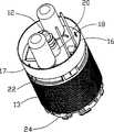
图1是本发明所述的无刷直流电机的一种实施例的透视图,1 is a perspective view of an embodiment of a brushless DC motor according to the present invention,
图2是图1所示电机的剖视图,Fig. 2 is a sectional view of the motor shown in Fig. 1,
图3是用来容纳图1和图2所示电机电子线路的器的分解透视图,Figure 3 is an exploded perspective view of the device used to house the electronic circuitry of the motor shown in Figures 1 and 2,
图4是图3中所示的容器的透视图,它安装在定子上并且容纳了电子线路,Figure 4 is a perspective view of the container shown in Figure 3, mounted on the stator and housing the electronics,
图5是图3所示的容器下方透视图,Fig. 5 is a bottom perspective view of the container shown in Fig. 3,
图6是电机的前绝缘体的透视图,Figure 6 is a perspective view of the front insulator of the motor,
图7是电机的转子的透视图,Figure 7 is a perspective view of the rotor of the motor,
图8是图7所示转子的部分剖视图,Fig. 8 is a partial sectional view of the rotor shown in Fig. 7,
图9是电机转子和定子的叠片结构的平面图,Fig. 9 is a plan view of the lamination structure of the motor rotor and stator,
图10是改进的转子叠片结构第二实施例的平面图,Fig. 10 is a plan view of a second embodiment of an improved rotor lamination structure,
图11是另一种改进的转子叠片结构的平面图,Figure 11 is a plan view of another improved rotor lamination structure,
图12是另一种定子的部分透视图,Fig. 12 is a partial perspective view of another stator,
图13是图11所示增加了磁通部件的定子的透视图。FIG. 13 is a perspective view of the stator shown in FIG. 11 with the addition of flux components.
具体实施方式Detailed ways
参照附图,此无刷直流电机包括一个深拉拔的外壳10,带有一个轴12的转子11,此轴在从外壳10的闭合端凸出部分具有一个平面12a,一个包围着转子11的缠绕定子13,一个闭合外壳10的端盖14,以及一个位于外壳10中用来容纳传感器和电路的容器16。缠绕定子13包括被定子叠片结构30缠绕的定子线圈19。Referring to the accompanying drawings, the brushless DC motor comprises a deep-drawn housing 10, a
这种电机具有和传统永磁体直流电机相似的外观,都具有包括换向器和电刷/叶片系统的换向部分。这种电机特别适用于燃油泵电机,但也具有其他的用途。This motor has a similar appearance to a conventional permanent magnet DC motor, with a commutation section consisting of a commutator and a brush/vane system. This motor is particularly useful as a fuel pump motor, but has other uses as well.
参照图3到5,容器16包括一个圆柱状的碗状物17,它具有一个从碗状物底部凸出的整体的套筒18。容器一般由树脂(POM)制成,它容纳了传感器,传感器一般是霍耳效应传感器,用来感知转子11相对于定子13的位置,容器也容纳了电子线路,它安装在和凸出的套筒18相配合安装的环形印刷电路板20上。理想情况下,霍耳效应传感器水平安置于印刷电路板20上。由于更加易于安装并且在完全封装后能够更加可靠的防油和防震,这样和传统的“直立的”霍耳效应传感器相比具有优势。同时,它也减少了传感器和永磁体转子平的顶部之间的距离。电路通过已知方式相应于传感器的输出来转换定子线圈中的电流,以使转子相对于定子转动。传感器和电路封装在电绝缘材料中,一般是环氧树脂,它充满或者基本上充满于容器16。套筒18是定尺度的以使得转子轴12可以穿过并且使得来自燃油泵的燃油流过。Referring to Figures 3 to 5,
传感器和大部分电子部件,包括所有的导电部分都完全封装。只有例如电子端子和大的电容器这些部件不必完全封装。The sensor and most of the electronics, including all conductive parts, are fully encapsulated. Only components such as electronic terminals and large capacitors do not have to be fully encapsulated.
如图5所示,碗状物17底部下面具有四个绝缘位移连接器21用来直接连接到定子13的线圈。容器16和它的附属物可以预装“插入”电机中。As shown in FIG. 5 , the bottom of the
由于通过套筒18的燃油的冷却作用,封装材料的导热性能并不是很重要。Due to the cooling effect of the fuel passing through the
图6详细地示出了安装在定子上的前部绝缘体22,它具有相同数量的槽23(本例中为四个)用来容纳定子线圈和容器16上的绝缘位移连接器21。FIG. 6 shows in detail the
代替在印刷电路板上安装传感器和电子电路的是,容器16的内部底表面可以印制成导电模板。这可以采取利用热压印机生成热压金属箔的方式。所有的电部件可以自动安装在碗状物的内表面随后进行封装。这种技术的另一个好处就是进一步减少霍耳传感器和转子磁极的平项部之间的距离,使得探测位置时磁场力增加。Instead of mounting the sensors and electronics on a printed circuit board, the inner bottom surface of the
电机也具有一个后部的绝缘体24,它与前部绝缘体22相似但并不完全相同。The motor also has a
端盖14这样连接于外壳10如通过在例如两个位置处卷曲外壳10的边缘到端盖上。这个端盖14支撑或限定了一个转子轴12的轴承,并且也包括了用户燃油泵所需要的整体特征。端盖14提供了终端26用来连接外部供电。The end cap 14 is attached to the housing 10 such as by crimping the edge of the housing 10 onto the end cap at, for example, two locations. This end cap 14 supports or defines a bearing for the
在电机的另一端安置有套筒15。套筒15一般由聚苯撑硫(PPS)制成。这种材料具有高的耐热空间稳定性,低的延伸性能以及特别好的抵抗各种腐蚀性燃油的性能。套筒15支撑或者限定了一个转子轴12的轴承,并且该套筒也用来通过压配到燃油泵外壳上的小孔中从而连接到用户的燃油泵上。通常,套筒15是泵外壳的一部分。现在它是电机的一部分。当它为了竞争目的用来支撑或者限定一个转子轴12的轴承以及充当泵外壳的连接/对准部件时,这种设计就更有优势了,并且它还可以使得电机供应给用户前做完全的测试。A sleeve 15 is arranged at the other end of the motor. The sleeve 15 is generally made of polyphenylene sulfide (PPS). This material has high thermal dimensional stability, low elongation and particularly good resistance to various aggressive fuels. The sleeve 15 supports or defines a bearing for the
和传统的换向器电机相比这种无刷直流电机使得半径和轴向尺寸的减少成为可能。Compared with conventional commutator motors, this brushless DC motor makes it possible to reduce the radial and axial dimensions.
参照附图7到11,转子包括转子轴12和用材料33浇铸而成并在浇铸后进行磁化的叠片铁芯27。Referring to Figures 7 to 11, the rotor comprises a
叠片铁芯27包括许多转子叠片结构29。如图9所示,这些叠片结构通过薄片金属冲压而成并且可以在冲压定子叠片结构30的同时冲压而成,以节省单独生产一个铁芯的成本。转子叠片29具有三个等角度布置的,径向朝内伸展的槽31和一个中心孔32,用来在转子轴12上安装叠片。一叠叠片30都用可磁化材料33浇铸而成,一般为热塑性结合的NdFeB化合物,并且这个(各向同性的)材料33在浇铸后磁化(如图7所示)。整体环34也浇铸而成,它可以象一个编码圆盘一样被装载用来在轴向产生较高的磁场力(对于霍耳传感器是必要的)。The
这种方式形成的转子不需要任何粘结并且易于装配,同时也不需要调整平衡。浇铸材料33也填充在槽31中。Rotors formed in this way do not require any bonding and are easy to assemble and require no balancing adjustments. The casting
图10给出了具有六个孔35的另一种转子叠片。这些孔35等角度布置,并且其中有三个孔比其他的大一些。这减少了转子铁芯27的重量,然而为了避免燃油泵转子冲力的损失(例如由于转子在液体里湍流而产生的损失),端部的叠片最好没有这样的孔35。FIG. 10 shows another rotor lamination with six holes 35 . The holes 35 are arranged at equal angles and three of them are larger than the others. This reduces the weight of the
图11给出了进一步的不具有槽31的转子叠片但是它具有不均匀的滚花外表面和六个相同尺寸的孔35’。Figure 11 shows a further rotor lamination without slots 31 but with a non-uniform knurled outer surface and six holes 35' of equal size.
图9所示的定子叠片30与转子叠片同时冲压而成,并且包括外环36,四个等角度布置沿径向向内伸展的磁极37,磁极37缠绕(图中未示出)了线圈,有四个磁通部件布置在每两个磁极37之间。因为磁极37和磁通部件38之间的小间隙,一叠这样的叠片比较难于缠绕。同时,随后会插入到外环上的环绕磁极外部缠绕线圈不推荐使用到小尺寸电机上去。The stator laminations 30 shown in FIG. 9 are stamped simultaneously with the rotor laminations, and include an outer ring 36, four equiangularly arranged magnetic poles 37 extending radially inward, and the magnetic poles 37 are wound (not shown) coil, with four flux components arranged between every two poles 37 . A stack of such laminations is relatively difficult to wind because of the small gap between the poles 37 and the flux members 38 . Also, the wraparound pole externally wound coil that is then inserted into the outer ring is not recommended for small size motors.
如图12和13所示的本发明的一方面,一种可选择的定子13’,具有In one aspect of the invention shown in Figures 12 and 13, an optional stator 13' having
外环36’,许多成角度布置从外环36’沿径向向内伸展的磁极37’,以及许多位于磁极37’之间的磁通部件38’。磁通部件38’与环36’和磁极37’相分离,并且可以移动进入由磁极37’缠绕线圈之后的外环36’限定的槽39中。这样简化了缠绕过程并且使得磁通部件38成形最佳。An outer ring 36', a plurality of angularly arranged magnetic poles 37' extending radially inwardly from the outer ring 36', and a plurality of flux members 38' between the magnetic poles 37'. The flux member 38' is separate from the ring 36' and the pole 37' and is movable into a slot 39 defined by the outer ring 36' after the pole 37' is wound around the coil. This simplifies the winding process and optimizes the shaping of the flux member 38 .
环36’和磁极37’是整体制成的并且可以由能够保证安装在一起的冲压叠片制成,这些叠片通过例如激光焊,成套冲压或者更多可选方式用可铸造的软磁烧结材料制成整体结构。The ring 36' and the poles 37' are made in one piece and may be made from stamped laminations which are guaranteed to fit together, for example by laser welding, stamping in sets or more alternatively sintered with a castable soft magnetic material to form a monolithic structure.
上述的实施方式仅仅通过具体实施例进行了描述,对本领域技术人员而言其不同的修改均是显而易见的,而不超出本发明附加权利要求所限定的保护范围。例如,转子可以环绕定子,这种情况一般常用作风机马达或者蓄电驱动器。The above implementations are only described through specific examples, and various modifications thereof will be obvious to those skilled in the art, without departing from the scope of protection defined by the appended claims of the present invention. For example, the rotor can surround the stator, which is often used as a fan motor or as an electric storage drive.
Claims (18)
Translated fromChineseApplications Claiming Priority (2)
| Application Number | Priority Date | Filing Date | Title |
|---|---|---|---|
| GB0130602.6 | 2001-12-21 | ||
| GBGB0130602.6AGB0130602D0 (en) | 2001-12-21 | 2001-12-21 | Brushless D.C. motor |
Related Child Applications (1)
| Application Number | Title | Priority Date | Filing Date |
|---|---|---|---|
| CNA2007100886807ADivisionCN101026328A (en) | 2001-12-21 | 2002-12-21 | Brushless DC motor |
Publications (2)
| Publication Number | Publication Date |
|---|---|
| CN1434557Atrue CN1434557A (en) | 2003-08-06 |
| CN100342626C CN100342626C (en) | 2007-10-10 |
Family
ID=9928126
Family Applications (3)
| Application Number | Title | Priority Date | Filing Date |
|---|---|---|---|
| CNB021611017AExpired - Fee RelatedCN100454721C (en) | 2001-12-21 | 2002-12-21 | Electric motor |
| CNB021400091AExpired - Fee RelatedCN100342626C (en) | 2001-12-21 | 2002-12-21 | Brushless dc motor |
| CNA2007100886807APendingCN101026328A (en) | 2001-12-21 | 2002-12-21 | Brushless DC motor |
Family Applications Before (1)
| Application Number | Title | Priority Date | Filing Date |
|---|---|---|---|
| CNB021611017AExpired - Fee RelatedCN100454721C (en) | 2001-12-21 | 2002-12-21 | Electric motor |
Family Applications After (1)
| Application Number | Title | Priority Date | Filing Date |
|---|---|---|---|
| CNA2007100886807APendingCN101026328A (en) | 2001-12-21 | 2002-12-21 | Brushless DC motor |
Country Status (10)
| Country | Link |
|---|---|
| US (3) | US7057318B2 (en) |
| EP (3) | EP1720235A3 (en) |
| JP (3) | JP2003224948A (en) |
| CN (3) | CN100454721C (en) |
| AT (2) | ATE344542T1 (en) |
| BR (2) | BR0205069A (en) |
| DE (2) | DE60215758T2 (en) |
| ES (2) | ES2273977T3 (en) |
| GB (1) | GB0130602D0 (en) |
| MX (3) | MXPA02012633A (en) |
Cited By (16)
| Publication number | Priority date | Publication date | Assignee | Title |
|---|---|---|---|---|
| CN102072168A (en)* | 2009-11-19 | 2011-05-25 | 现代自动车株式会社 | Electric water pump |
| US7956505B2 (en) | 2006-04-25 | 2011-06-07 | Lg Electronics Inc. | Rotor of electric motor for simplifying manufacturing process and electric motor having the same |
| US8292598B2 (en) | 2004-11-23 | 2012-10-23 | Entegris, Inc. | System and method for a variable home position dispense system |
| US8382444B2 (en) | 2005-12-02 | 2013-02-26 | Entegris, Inc. | System and method for monitoring operation of a pump |
| CN101356373B (en)* | 2004-11-23 | 2013-07-17 | 恩特格里公司 | System for position control of a mechanical piston in a pump |
| US8651823B2 (en) | 2005-11-21 | 2014-02-18 | Entegris, Inc. | System and method for a pump with reduced form factor |
| US8678775B2 (en) | 2005-12-02 | 2014-03-25 | Entegris, Inc. | System and method for position control of a mechanical piston in a pump |
| US8753097B2 (en) | 2005-11-21 | 2014-06-17 | Entegris, Inc. | Method and system for high viscosity pump |
| US8839503B2 (en) | 2009-11-19 | 2014-09-23 | Hyundai Motor Company | Method for manufacturing stator for electric water pump |
| US8870548B2 (en) | 2005-12-02 | 2014-10-28 | Entegris, Inc. | System and method for pressure compensation in a pump |
| US8961154B2 (en) | 2009-11-19 | 2015-02-24 | Hyundai Motor Company | Electric water pump |
| CN105071625A (en)* | 2015-07-31 | 2015-11-18 | 常州市昊升电机有限公司 | Novel high-speed brushless motor |
| CN103016324B (en)* | 2005-11-21 | 2016-08-10 | 恩特格里公司 | The system and method for the position control of the mechanical piston in pump |
| US9631611B2 (en) | 2006-11-30 | 2017-04-25 | Entegris, Inc. | System and method for operation of a pump |
| CN108141117A (en)* | 2015-10-20 | 2018-06-08 | 三菱电机株式会社 | The manufacturing method and manufacturing device of the rotor of motor |
| CN109555718A (en)* | 2019-01-24 | 2019-04-02 | 全小华 | High-speed permanent-magnet brushless axial flow blower |
Families Citing this family (135)
| Publication number | Priority date | Publication date | Assignee | Title |
|---|---|---|---|---|
| JP4408674B2 (en)* | 2003-09-29 | 2010-02-03 | 愛三工業株式会社 | Fuel pump |
| GB0327023D0 (en)* | 2003-11-20 | 2003-12-24 | Head Philip | Electric motors for powering downhole tools |
| DE10356078A1 (en) | 2003-12-01 | 2005-06-23 | Siemens Ag | Engine for a fuel pump |
| JP4613596B2 (en)* | 2004-04-02 | 2011-01-19 | 株式会社デンソー | Fuel supply device |
| DE102005015014A1 (en)* | 2004-04-02 | 2005-11-03 | Denso Corp., Kariya | Fuel pump, fuel supply device using the fuel pump and method of manufacturing the fuel pump |
| US7247967B2 (en) | 2004-08-09 | 2007-07-24 | A. O. Smith Corporation | Electric motor having a stator |
| US7737598B2 (en) | 2004-08-09 | 2010-06-15 | A. O. Smith Corporation | Electric motor having a stator |
| JP2006299954A (en)* | 2005-04-21 | 2006-11-02 | Hitachi Ltd | Fuel pump |
| KR100653434B1 (en)* | 2005-04-29 | 2006-12-01 | 영 춘 정 | 2-phase rectifier motor |
| EP1884010B1 (en)* | 2005-05-17 | 2014-04-30 | Carter Fuel Systems, LLC | Bldc motor and pump assembly with encapsulated circuit board |
| KR100664065B1 (en)* | 2005-06-20 | 2007-01-03 | 엘지전자 주식회사 | Magnet fixing structure of electric motor |
| WO2007012370A1 (en)* | 2005-07-26 | 2007-02-01 | Ebm-Papst St. Georgen Gmbh & Co. Kg | Brushless electric motor |
| JP4696855B2 (en)* | 2005-11-02 | 2011-06-08 | 株式会社デンソー | Fuel pump |
| JP2007151314A (en)* | 2005-11-29 | 2007-06-14 | Matsushita Electric Ind Co Ltd | motor |
| WO2007062766A1 (en)* | 2005-12-01 | 2007-06-07 | Emb-Papst St. Georgen Gmbh & Co. Kg | Electric motor |
| US7566999B2 (en)* | 2006-07-19 | 2009-07-28 | Encap Technologies Inc. | Electromagnetic device with composite structure heat transfer flow path |
| US7931448B2 (en) | 2006-08-01 | 2011-04-26 | Federal Mogul World Wide, Inc. | System and method for manufacturing a brushless DC motor fluid pump |
| US20080073986A1 (en)* | 2006-09-26 | 2008-03-27 | Lg Electronics Inc. | Permanent magnet rotor type motor and method for manufacturing the same |
| DE502007005829D1 (en)* | 2007-01-17 | 2011-01-13 | W & H Dentalwerk Buermoos Gmbh | Medical handle |
| US8253285B2 (en)* | 2007-04-27 | 2012-08-28 | Hitachi Koki Co., Ltd. | Power tool |
| JP4974054B2 (en)* | 2007-04-27 | 2012-07-11 | 日立工機株式会社 | Electric tool |
| CN101680403B (en)* | 2007-05-01 | 2013-06-12 | 超级汽车工业和贸易公司 | Novelty in electric fuel pumps for internal combustion engines |
| US7847457B2 (en)* | 2007-05-09 | 2010-12-07 | Federal-Mogul World Wide, Inc | BLDC motor assembly |
| US8033007B2 (en) | 2007-05-11 | 2011-10-11 | Sntech, Inc. | Method of making rotor of brushless motor |
| US8299661B2 (en) | 2007-05-11 | 2012-10-30 | Sntech Inc. | Rotor of brushless motor |
| WO2008146502A1 (en)* | 2007-05-25 | 2008-12-04 | Mitsubishi Electric Corporation | Brushless motor |
| US7874817B2 (en)* | 2007-06-01 | 2011-01-25 | Ti Group Automotive Systems, L.L.C. | Fuel pump assembly with a vapor purge passage arrangement for a fuel pump module |
| US7960931B2 (en)* | 2007-06-15 | 2011-06-14 | Illinois Institute Of Technology | Digital control of motor drives |
| FR2919971B1 (en)* | 2007-08-06 | 2009-10-16 | Leroy Somer Moteurs | ELECTRIC GENERATOR AND INSTALLATION COMPRISING A LIGHTING TOWER SUPPLIED BY SUCH A GENERATOR |
| DE202007018933U1 (en)* | 2007-10-02 | 2009-11-12 | Kolektor Kautt & Bux Gmbh | Winding connection device for an electric motor or generator |
| CN201118414Y (en)* | 2007-10-29 | 2008-09-17 | 深圳航天科技创新研究院 | Square wave three-phase brushless permanent magnet DC motor |
| KR100946719B1 (en)* | 2007-11-28 | 2010-03-12 | 영 춘 정 | Multi-programmable constant flow control device of variable speed non-commutator motor |
| US7795827B2 (en)* | 2008-03-03 | 2010-09-14 | Young-Chun Jeung | Control system for controlling motors for heating, ventilation and air conditioning or pump |
| WO2009126853A2 (en)* | 2008-04-11 | 2009-10-15 | Cooper Standard Automotive, Inc. | Rotor assembly including sintered magnet core assembly |
| US20090284201A1 (en)* | 2008-05-15 | 2009-11-19 | Young-Chun Jeung | Motor with magnetic sensors |
| US8504646B2 (en)* | 2008-06-23 | 2013-08-06 | Sntech, Inc. | Data transfer between motors |
| US8138710B2 (en)* | 2008-08-14 | 2012-03-20 | Sntech Inc. | Power drive of electric motor |
| US20100039055A1 (en)* | 2008-08-14 | 2010-02-18 | Young-Chun Jeung | Temperature control of motor |
| CN101666279B (en)* | 2008-09-03 | 2014-02-19 | 德昌电机(深圳)有限公司 | fuel pump |
| DE102008055731B4 (en)* | 2008-11-04 | 2014-07-31 | Knf Neuberger Gmbh | Brushless DC motor |
| DE102009013374B4 (en)* | 2009-03-07 | 2019-08-14 | Ziehl-Abegg Se | Rotor for electric motors, permanent magnet for such a rotor and electric machine with a rotor |
| DE102009001808A1 (en)* | 2009-03-24 | 2010-09-30 | Robert Bosch Gmbh | electric motor |
| US8232755B2 (en) | 2009-04-02 | 2012-07-31 | Young-Chun Jeung | Motor with circuits for protecting motor from input power outages or surges |
| BRMU8900643Y1 (en)* | 2009-04-17 | 2017-04-25 | Robert Bosch Ltda | housing for the control electronics of a brushless dc motor |
| DE102009024014A1 (en)* | 2009-06-05 | 2010-12-09 | Minebea Co., Ltd., Miyota-machi | Rotor for permanent magnet motor, has shaft and rotor body which is connected with shaft in rotably fixed manner, where anisotropic multipolar drive magnet is formed at rotor body |
| KR101041165B1 (en)* | 2009-07-14 | 2011-06-13 | 엘지이노텍 주식회사 | Stator core of the motor |
| BR112012003841A2 (en)* | 2009-08-19 | 2017-08-08 | Hoffman Enclosures Inc D/Ba Pentair Technical Products | magnetic motor pump assembly with integrated motor |
| KR101098748B1 (en)* | 2009-10-01 | 2011-12-23 | (주) 디에이치홀딩스 | Brushless DC motor for fuel pump |
| JP2011167024A (en)* | 2010-02-15 | 2011-08-25 | Minebea Co Ltd | Dc brushless motor device |
| US8378618B2 (en)* | 2010-02-19 | 2013-02-19 | Sntech, Inc. | Systems and methods for controlling operations of a motor |
| EP2543132A2 (en) | 2010-03-05 | 2013-01-09 | Kappel, Andreas | Electromechanical motor |
| US20110274556A1 (en)* | 2010-05-04 | 2011-11-10 | Adda Corporation | Positioning structure for stator assembly of cooling fan |
| CN102237760A (en)* | 2010-05-07 | 2011-11-09 | 上海宝钢汽车检测修复有限公司 | Motor of electrically-driven coach car |
| JP2011239546A (en)* | 2010-05-10 | 2011-11-24 | Makita Corp | Dc brushless motor |
| KR101115498B1 (en)* | 2010-05-19 | 2012-02-27 | 성장연 | Brushless DC Motor |
| EP2580850B1 (en)* | 2010-06-14 | 2021-11-10 | Black & Decker, Inc. | Control unit for brushless motor in a power tool |
| CN201774430U (en)* | 2010-07-29 | 2011-03-23 | 中山大洋电机制造有限公司 | A new motor mechanism |
| JP5229642B2 (en)* | 2010-08-06 | 2013-07-03 | 株式会社デンソー | Motor and electric power steering apparatus using the same |
| US9138818B2 (en)* | 2010-08-16 | 2015-09-22 | Emerson Electric Co. | Systems and devices for performing powered threading operations |
| DE102011110752A1 (en) | 2010-08-20 | 2012-03-15 | Johnson Electric S.A. | Brushless motor |
| US8581466B2 (en) | 2010-08-27 | 2013-11-12 | Hamilton Sundstrand Corporation | Knurled multiple conductor windings |
| CN101951109B (en)* | 2010-10-12 | 2012-03-28 | 彭希南 | Direct Drive Permanent Magnet Brushless DC Motor |
| DE102010049054A1 (en)* | 2010-10-15 | 2012-04-19 | Ziehl-Abegg Ag | Rotor i.e. internal rotor, for electronically commutated internal electric motor, has permanent magnets arranged one behind other in non-uniform spacings for formation of pole gaps spaced along circumferential direction |
| EP2475075A1 (en)* | 2011-01-05 | 2012-07-11 | Robert Bosch GmbH | Motor construction |
| TW201233005A (en)* | 2011-01-18 | 2012-08-01 | Yen Shen Electric Ind Co Ltd | Motor rotor capable of being separately applied to two magnetic units |
| EP2670031B1 (en)* | 2011-01-26 | 2020-07-01 | Makita Corporation | Brushless motor for power tool |
| CN201947080U (en)* | 2011-01-28 | 2011-08-24 | 中山大洋电机制造有限公司 | A brushless motor rotor structure |
| US20140111045A1 (en) | 2011-05-15 | 2014-04-24 | Andreas Kappel | Rotary drive |
| CN102213151A (en)* | 2011-05-17 | 2011-10-12 | 遵义天义利威机电有限责任公司 | Controller of non-position sensor direct current brushless electric fuel pump for automobile |
| DE102011082577A1 (en)* | 2011-09-13 | 2013-03-14 | Robert Bosch Gmbh | Gear pump and method of manufacturing a gear pump |
| DE102011084702A1 (en)* | 2011-10-18 | 2013-04-18 | Continental Automotive Gmbh | Method of making a BLDC motor |
| US8896169B2 (en) | 2011-10-31 | 2014-11-25 | Regal Beloit America, Inc. | Methods and apparatus for mounting a motor controller on a stator assembly |
| KR200463261Y1 (en) | 2011-11-29 | 2012-10-25 | 금산전자 주식회사 | Connector deveic for brushless motor |
| US20130140938A1 (en)* | 2011-12-05 | 2013-06-06 | GM Global Technology Operations LLC | Balanced rotor core with reduced mass and inertia laminations |
| US8679210B2 (en) | 2012-01-17 | 2014-03-25 | Hamilton Sundstrand Corporation | Shrouded particle separator |
| CN104136779B (en)* | 2012-02-27 | 2016-10-26 | 麦格纳动力系巴德霍姆堡有限责任公司 | Pump installation |
| DE102012209905A1 (en)* | 2012-06-13 | 2013-12-19 | Krones Ag | Capper for containers |
| US20130342041A1 (en)* | 2012-06-15 | 2013-12-26 | Black & Decker Inc. | Stator assembly for a brushless motor in a power tool |
| WO2013190640A1 (en)* | 2012-06-19 | 2013-12-27 | 三菱電機株式会社 | Pump, method for manufacturing pump, and refrigeration cycle device |
| DE102012211183A1 (en)* | 2012-06-28 | 2014-01-02 | Robert Bosch Gmbh | Power tool |
| DE102012213051A1 (en)* | 2012-07-25 | 2014-01-30 | Robert Bosch Gmbh | Hand tool |
| TWI584905B (en)* | 2012-07-27 | 2017-06-01 | 鴻準精密工業股份有限公司 | Method for manufacturing fan impeller |
| JP2014042441A (en)* | 2012-08-22 | 2014-03-06 | Samsung Electro-Mechanics Co Ltd | Switched reluctance motor assembly |
| US9169833B2 (en) | 2012-10-04 | 2015-10-27 | Carter Fuel Systems, Llc | Device for fastening and electrically connecting a circuit board to a motor |
| KR101245176B1 (en) | 2012-10-19 | 2013-03-25 | 송병로 | Moter by using coil winding of etching foil type |
| WO2014071147A1 (en)* | 2012-11-01 | 2014-05-08 | Hypertronics Corporation | Rotary electrical interconnect device |
| US10821591B2 (en) | 2012-11-13 | 2020-11-03 | Milwaukee Electric Tool Corporation | High-power cordless, hand-held power tool including a brushless direct current motor |
| JP2014103721A (en)* | 2012-11-16 | 2014-06-05 | Aisin Seiki Co Ltd | Brushless motor |
| TWI516000B (en)* | 2013-08-20 | 2016-01-01 | 林聖梁 | Motor |
| KR101482939B1 (en) | 2013-08-20 | 2015-01-15 | 박정희 | Hall Sensor Fastening Structure of BLDC Motor |
| US9712002B2 (en)* | 2013-08-23 | 2017-07-18 | Magna Powertrain Bad Homburg GmbH | Interlocked stator yoke and star for electric motor |
| JP6275415B2 (en)* | 2013-08-29 | 2018-02-07 | 東京パーツ工業株式会社 | Brushless motor |
| JP6234128B2 (en)* | 2013-09-11 | 2017-11-22 | 株式会社マキタ | Electric tool |
| CN103590941A (en)* | 2013-10-24 | 2014-02-19 | 安徽工贸职业技术学院 | Anticorrosive fuel pump |
| DE102013222534A1 (en)* | 2013-11-06 | 2015-05-07 | Robert Bosch Gmbh | electric machine |
| US10253676B2 (en) | 2013-12-20 | 2019-04-09 | Magna Powertrain Bad Homburg GmbH | Molded rotor for cooling fan motor |
| CN105099013B (en)* | 2014-04-23 | 2019-05-03 | 德昌电机(深圳)有限公司 | The motor of motor stator component and the application stator module |
| US9759236B2 (en) | 2014-04-25 | 2017-09-12 | Hamilton Sundstrand Corporation | Inlet tube design |
| CN104033351A (en)* | 2014-07-01 | 2014-09-10 | 江苏恒康机电有限公司 | Oil pump motor set for multi-pump hydraulic system |
| EP3168963B1 (en)* | 2014-07-08 | 2022-06-01 | Mitsubishi Electric Corporation | Rotor of electric motor, electric motor, and air conditioner |
| EP2991195A1 (en)* | 2014-09-01 | 2016-03-02 | Siemens Aktiengesellschaft | Permanently excited dynamoelectric machine |
| US10224779B2 (en)* | 2014-10-02 | 2019-03-05 | Regal Beloit America, Inc. | Electric machine, barrier and associated kit |
| EP3197025B1 (en) | 2014-11-25 | 2020-10-28 | Black & Decker Inc. | Brushless motor for a power tool |
| US10693344B2 (en) | 2014-12-18 | 2020-06-23 | Black & Decker Inc. | Packaging of a control module for a brushless motor |
| KR101697704B1 (en)* | 2015-05-27 | 2017-01-19 | 디와이오토 주식회사 | Stator apparatus for brushless motor |
| JP2017017919A (en)* | 2015-07-03 | 2017-01-19 | 株式会社ジェイテクト | Manufacturing method of rotor, and rotor |
| JP2017017920A (en)* | 2015-07-03 | 2017-01-19 | 株式会社ジェイテクト | Rotor manufacturing method and rotor |
| JP6308177B2 (en)* | 2015-06-26 | 2018-04-11 | 株式会社デンソー | Rotor |
| WO2017047264A1 (en) | 2015-09-18 | 2017-03-23 | アイシン・エィ・ダブリュ株式会社 | Rotating electric machine and stator |
| US10500708B2 (en) | 2015-10-14 | 2019-12-10 | Black & Decker Inc. | Power tool |
| US10308307B2 (en)* | 2016-02-16 | 2019-06-04 | Allied Treasure Inc., Limited | Disk-type electric motor, electrically driven vehicle and method for controlling the same |
| EP3436221B1 (en) | 2016-03-30 | 2021-12-15 | Milwaukee Electric Tool Corporation | Brushless motor for a power tool |
| DE102016205252A1 (en)* | 2016-03-30 | 2017-10-05 | Mahle International Gmbh | Bearing arrangement of a motor shaft of an electric motor |
| DE112017001982A5 (en)* | 2016-04-12 | 2018-12-27 | Magna Powertrain Bad Homburg GmbH | DRIVE ARRANGEMENT |
| TWI654370B (en)* | 2016-06-15 | 2019-03-21 | 泓記精密股份有限公司 | Electric fuel pump |
| CN106337824B (en) | 2016-09-28 | 2018-10-23 | 浙江亿利达风机股份有限公司 | A kind of volute casing centrifugal blower fan of novel belt permanent magnetic brushless system |
| CN106194770B (en)* | 2016-09-30 | 2019-05-07 | 克奥兹泵业(深圳)有限公司 | Small Minitype centrifugal water pump |
| DE102017107612A1 (en)* | 2017-04-10 | 2018-10-11 | Valeo Systèmes d'Essuyage | Brushless electric motor and method of manufacturing the electric motor |
| US10840776B2 (en) | 2017-05-27 | 2020-11-17 | Actuator Electric Motors | Self-contained brushless motor and brushless controller |
| DE102017209621A1 (en)* | 2017-06-08 | 2018-12-13 | Robert Bosch Gmbh | Drive unit with an electronically commutated motor and an electronics unit |
| DE102017121215A1 (en)* | 2017-09-13 | 2019-03-14 | Valeo Systèmes d'Essuyage | Brushless electric motor |
| CN109256884A (en)* | 2017-10-13 | 2019-01-22 | 朱卫 | A kind of motor case produced with titanium |
| JP2019106778A (en)* | 2017-12-12 | 2019-06-27 | 東京パーツ工業株式会社 | Motor and actuator unit |
| DE102017223514A1 (en) | 2017-12-21 | 2019-06-27 | Adient Aerospace Llc | Electromechanical drive unit for controlling a moving part of an adjusting unit and adjusting unit |
| US11139722B2 (en) | 2018-03-02 | 2021-10-05 | Black & Decker Inc. | Motor having an external heat sink for a power tool |
| DE102018219359A1 (en)* | 2018-11-13 | 2020-05-14 | Zf Friedrichshafen Ag | Electric drive unit and transmission for a motor vehicle |
| DE102019104706A1 (en) | 2019-02-25 | 2020-08-27 | Nidec Gpm Gmbh | Electrical contacting of stator connections on a printed circuit board by means of horizontally aligned insulation displacement contacts |
| US11462981B2 (en) | 2019-08-28 | 2022-10-04 | Hossam Abdou | Electric motor |
| EP3829041A1 (en)* | 2019-11-29 | 2021-06-02 | Hilti Aktiengesellschaft | Hall board within winding heads |
| DE102020202781A1 (en)* | 2020-03-04 | 2021-09-09 | Siemens Aktiengesellschaft | 8Electric motor with can |
| US12088160B2 (en) | 2020-12-23 | 2024-09-10 | Black & Decker Inc. | Brushless DC motor with circuit board for winding interconnections |
| KR20220118907A (en) | 2021-02-19 | 2022-08-26 | 제이엔씨 주식회사 | Liquid crystal composition and liquid crystal display device |
| US11916447B2 (en)* | 2021-06-07 | 2024-02-27 | Black & Decker Inc. | Overmolded rotor structure |
| US12068639B2 (en) | 2021-06-07 | 2024-08-20 | Black & Decker Inc. | Motor rotor with sleeve for retention of magnet ring |
| CN113241902B (en)* | 2021-06-29 | 2022-08-26 | 中汽创智科技有限公司 | Motor and braking system |
Family Cites Families (81)
| Publication number | Priority date | Publication date | Assignee | Title |
|---|---|---|---|---|
| US3644067A (en)* | 1970-05-25 | 1972-02-22 | Sperry Rand Corp | Power transmission |
| GB1340800A (en)* | 1971-10-18 | 1973-12-12 | Gen Motors Corp | Electric fuel pump assemblies |
| US3873861A (en)* | 1973-06-15 | 1975-03-25 | Richard Halm | Electric motor, especially a squirrel-cage motor |
| DE2628729A1 (en) | 1976-06-25 | 1978-01-05 | Teldix Gmbh | Brushless DC motor with internal stator - has plug connections between machine and electronic control circuits |
| US4186319A (en) | 1977-04-26 | 1980-01-29 | General Electric Company | Dynamoelectric machine end shield |
| JPS57148567A (en)* | 1981-03-09 | 1982-09-13 | Hitachi Metals Ltd | Cylindrical magnet and manufacture thereof |
| DE3126100A1 (en)* | 1981-07-02 | 1983-01-20 | Robert Bosch Gmbh, 7000 Stuttgart | Device for mounting and cooling a power transistor |
| US4508492A (en)* | 1981-12-11 | 1985-04-02 | Nippondenso Co., Ltd. | Motor driven fuel pump |
| US5418416A (en)* | 1983-09-05 | 1995-05-23 | Papst Licensing Gmbh | Brushless three-phase DC motor |
| US4504755A (en) | 1983-11-03 | 1985-03-12 | Kollmorgen Technologies Corporation | Rotor reluctance notch for cogging control |
| JPH0744795B2 (en)* | 1984-03-09 | 1995-05-15 | 松下電器産業株式会社 | Non-commutator motor rotor |
| GB2157766B (en)* | 1984-04-25 | 1988-01-20 | Facet Enterprises | Rotary fuel-pump for an i.c.engine |
| JPS61280752A (en)* | 1985-06-05 | 1986-12-11 | Oopack Kk | Brushless dc rotary electric machine |
| JPH0442559Y2 (en)* | 1985-10-03 | 1992-10-07 | ||
| JPS61210857A (en)* | 1986-03-19 | 1986-09-19 | Hitachi Ltd | permanent magnet synchronous motor |
| JPS62235523A (en)* | 1986-03-19 | 1987-10-15 | Honda Motor Co Ltd | Manufacture of rotational angle sensor |
| EP0267269A4 (en) | 1986-05-12 | 1988-09-28 | Ronald W Henck | Electric motor and method for manufacturing the same. |
| US4789308A (en)* | 1986-10-10 | 1988-12-06 | Walbro Corporation | Self-contained electric fuel pump with output pressure regulation |
| US4737674A (en)* | 1986-10-17 | 1988-04-12 | Shicoh Engineering Co., Ltd. | Single phase brushless motor with a core |
| DE3710658A1 (en)* | 1987-03-31 | 1988-10-13 | Standard Elektrik Lorenz Ag | ELECTRONICALLY COMMUTED, COLLECTORLESS DC MOTOR |
| JPH0828293B2 (en)* | 1987-04-07 | 1996-03-21 | 日立金属株式会社 | Cylindrical permanent magnet, motor using the same, and manufacturing method thereof |
| GB2217924B (en)* | 1988-04-25 | 1992-10-07 | Matsushita Electric Works Ltd | Permanent magnet rotor |
| IT1220410B (en)* | 1988-06-29 | 1990-06-15 | Gd Spa | DEVICE FOR DRILLING PERFORATIONS IN BAR-SHAPED ITEMS |
| US4998865A (en)* | 1988-07-11 | 1991-03-12 | Aisan Kogyo Kabushiki Kaisha | Brushless DC pump with enclosed circuit board |
| US5053664A (en)* | 1989-01-18 | 1991-10-01 | Aisan Kogyo Kabushiki Kaisha | Motor-driven fuel pump |
| JPH02311147A (en)* | 1989-05-25 | 1990-12-26 | Seiko Epson Corp | Composite cylindrical permanent magnet |
| JPH0333494A (en)* | 1989-06-29 | 1991-02-13 | Mitsubishi Electric Corp | In-tank type motor-driven pump |
| SI8912097B (en) | 1989-10-30 | 1999-04-30 | Iskra-Elektromotorji, P.O., | Single-phase direct current motor without brushes with high speed and high power |
| US5145614A (en)* | 1990-02-14 | 1992-09-08 | Canon Kabushiki Kaisha | Process for preparing magnet made of resin |
| EP0464644B2 (en) | 1990-07-06 | 2000-01-05 | Hitachi, Ltd. | Brushless motor incorporating an integrated circuit having a one-chipped peripheral circuit |
| US5356272A (en)* | 1990-09-05 | 1994-10-18 | Nippondenso Co., Ltd. | Fuel supply device and method of assembling same |
| JP3123183B2 (en) | 1991-02-08 | 2001-01-09 | 株式会社デンソー | Vehicle fuel supply system |
| CN2121766U (en)* | 1991-07-16 | 1992-11-11 | 德昌电机股份有限公司 | Motor |
| US5221503A (en)* | 1991-10-28 | 1993-06-22 | General Motors Corporation | Method for manufacturing a dynamoelectric device |
| DE4201401A1 (en)* | 1992-01-21 | 1993-07-22 | Bosch Gmbh Robert | Displacement pump conveying fuel in motor vehicle - has drive motor installed into jar-shaped housing as complete prefabricated component of motor housing |
| JPH05207718A (en) | 1992-01-24 | 1993-08-13 | Nippon Densan Corp | DC motor |
| CN1031439C (en)* | 1992-03-18 | 1996-03-27 | 武昆山 | Three-phase induction motor |
| JPH05284678A (en)* | 1992-03-31 | 1993-10-29 | Mabuchi Motor Co Ltd | Miniature motor |
| US5402024A (en)* | 1992-04-06 | 1995-03-28 | Matsushita Electric Industrial Co., Ltd. | Rotor for a permanent-magnet motor |
| JPH05292689A (en)* | 1992-04-06 | 1993-11-05 | Matsushita Electric Ind Co Ltd | Rotor of permanent magnet motor |
| JPH06280707A (en)* | 1993-03-24 | 1994-10-04 | Aisan Ind Co Ltd | Electric motor-driven fuel pump |
| US5345130A (en)* | 1993-04-28 | 1994-09-06 | General Electric Company | Modable permanent magnet rotor for optimized field shaping |
| AU682393B2 (en)* | 1993-10-13 | 1997-10-02 | Ebara Corporation | Motor stator assembly and full-circumferential flow pump employing such motor stator assembly |
| KR0118819Y1 (en)* | 1993-11-30 | 1998-07-15 | 김광호 | Door opening and closing device of refrigerator |
| JPH07184339A (en)* | 1993-12-24 | 1995-07-21 | Asmo Co Ltd | Motor mounting structure |
| JPH07203645A (en)* | 1993-12-30 | 1995-08-04 | Mabuchi Motor Co Ltd | Manufacturing method of small motor and rotor thereof |
| US5393206A (en)* | 1994-06-29 | 1995-02-28 | General Motors Corporation | Fuel pump for a motor vehicle |
| JPH08126265A (en) | 1994-09-02 | 1996-05-17 | Sankyo Seiki Mfg Co Ltd | Rotating electric machine |
| US5961293A (en)* | 1995-05-19 | 1999-10-05 | Uis, Inc | In-take fuel pump assembly with unitary control unit for internal combustion engines |
| JP3487679B2 (en)* | 1995-06-14 | 2004-01-19 | 三洋電機株式会社 | Small electric motor |
| JPH09215236A (en) | 1996-02-06 | 1997-08-15 | Daikin Ind Ltd | Brushless DC motor |
| BR9601756A (en)* | 1996-05-29 | 1998-09-29 | Brasil Compressores Sa | Electric motor rotor cover |
| US5717268A (en)* | 1996-06-17 | 1998-02-10 | Philips Electronics North America Corp. | Electric motor with tachometer signal generator |
| DE19705974A1 (en)* | 1997-02-17 | 1998-08-20 | Wilo Gmbh | Electric motor for a pump or a fan |
| US6025665A (en)* | 1997-02-21 | 2000-02-15 | Emerson Electric Co. | Rotating machine for use in a pressurized fluid system |
| JPH10285895A (en)* | 1997-03-31 | 1998-10-23 | Kusatsu Denki Kk | Brushless motor rotor |
| KR19980075864A (en)* | 1997-04-02 | 1998-11-16 | 윤종용 | Brushless DC Motor |
| US5898990A (en)* | 1997-04-14 | 1999-05-04 | General Motors Corporation | Method of assembling a magnet ring on a rotor |
| US5920437A (en)* | 1997-05-08 | 1999-07-06 | Sankyo Seiki Mfg. Co., Ltd. | Objective lens driving apparatus |
| BR9702802A (en)* | 1997-08-28 | 2000-02-15 | Brasil Compressores Sa | Rotor for electric motor. |
| JPH11136889A (en)* | 1997-10-28 | 1999-05-21 | Toshiba Corp | Permanent magnet type motor and manufacturing method thereof |
| US5939807A (en)* | 1997-12-16 | 1999-08-17 | Reliance Electric Industrial Company | Cap mounted drive for a brushless DC motor |
| JPH11299207A (en)* | 1998-04-17 | 1999-10-29 | Matsushita Electric Ind Co Ltd | Brushless motor |
| JP3318531B2 (en) | 1998-08-04 | 2002-08-26 | ミネベア株式会社 | Rotating electric machine and its bearing structure |
| DE19836451C2 (en)* | 1998-08-12 | 2000-05-31 | Baermann Max Gmbh | Highly filled plastic part |
| DE19842170A1 (en)* | 1998-09-15 | 2000-03-16 | Wilo Gmbh | Contacting motor windings |
| JP2000102201A (en)* | 1998-09-18 | 2000-04-07 | Toshiba Corp | Permanent magnet rotor and manufacturing method thereof |
| JP2000156963A (en)* | 1998-11-19 | 2000-06-06 | Moriyama Kogyo Kk | Magnetic pole position detecting device for brushless DC motor and annular sheet with thin plate magnet |
| DE19904162C2 (en)* | 1999-02-03 | 2000-11-23 | Pierburg Ag | Fuel electric motor pump |
| JP3881126B2 (en)* | 1999-03-05 | 2007-02-14 | アスモ株式会社 | motor |
| JP2000287430A (en)* | 1999-03-29 | 2000-10-13 | Matsushita Electric Ind Co Ltd | Brushless motor, pump using the same, and method of magnetizing brushless motor magnet |
| US6231318B1 (en)* | 1999-03-29 | 2001-05-15 | Walbro Corporation | In-take fuel pump reservoir |
| JP2000354392A (en)* | 1999-06-09 | 2000-12-19 | Denso Corp | Brushless motor |
| JP2001078382A (en)* | 1999-06-30 | 2001-03-23 | Asmo Co Ltd | Brushless motor and air conditioner for vehicle |
| JP2001037124A (en)* | 1999-07-27 | 2001-02-09 | Hitachi Metals Ltd | Rotor |
| JP2001178040A (en)* | 1999-12-21 | 2001-06-29 | Mitsubishi Electric Corp | Method for manufacturing rotor of permanent magnet type motor for compressor and rotor of permanent magnet type motor for compressor, compressor and refrigeration cycle |
| JP2001204160A (en) | 2000-01-20 | 2001-07-27 | Fujitsu General Ltd | Magnetization method of DC brushless motor |
| DE60123581T2 (en)* | 2000-02-09 | 2007-06-21 | Parker-Hannifin Corp., Cleveland | MOTOR PUMP UNIT |
| KR100334535B1 (en)* | 2000-02-18 | 2002-05-03 | 박종섭 | Multi-bit counter |
| US6734589B2 (en)* | 2001-05-10 | 2004-05-11 | Mitsuba Corporation | Electric motor |
| US6784582B1 (en)* | 2001-11-19 | 2004-08-31 | Valeo Electrical Systems, Inc. | Magnet shaping and pole concentration for reduction of cogging torque in permanent magnet motors |
- 2001
- 2001-12-21GBGBGB0130602.6Apatent/GB0130602D0/ennot_activeCeased
- 2002
- 2002-12-13EPEP06016904Apatent/EP1720235A3/ennot_activeWithdrawn
- 2002-12-13ATAT02258614Tpatent/ATE344542T1/ennot_activeIP Right Cessation
- 2002-12-13ESES02258614Tpatent/ES2273977T3/ennot_activeExpired - Lifetime
- 2002-12-13ESES02258610Tpatent/ES2316527T3/ennot_activeExpired - Lifetime
- 2002-12-13ATAT02258610Tpatent/ATE413008T1/ennot_activeIP Right Cessation
- 2002-12-13EPEP02258610Apatent/EP1324474B1/ennot_activeExpired - Lifetime
- 2002-12-13DEDE60215758Tpatent/DE60215758T2/ennot_activeExpired - Lifetime
- 2002-12-13DEDE60229615Tpatent/DE60229615D1/ennot_activeExpired - Lifetime
- 2002-12-13EPEP02258614Apatent/EP1324465B1/ennot_activeExpired - Lifetime
- 2002-12-18MXMXPA02012633Apatent/MXPA02012633A/enactiveIP Right Grant
- 2002-12-18MXMXPA02012632Apatent/MXPA02012632A/enactiveIP Right Grant
- 2002-12-18BRBR0205069-2Apatent/BR0205069A/ennot_activeIP Right Cessation
- 2002-12-18USUS10/321,368patent/US7057318B2/ennot_activeExpired - Lifetime
- 2002-12-18BRBR0205068-4Apatent/BR0205068A/ennot_activeIP Right Cessation
- 2002-12-19JPJP2002367753Apatent/JP2003224948A/enactivePending
- 2002-12-19JPJP2002367754Apatent/JP4414647B2/ennot_activeExpired - Fee Related
- 2002-12-19USUS10/322,520patent/US7215052B2/ennot_activeExpired - Fee Related
- 2002-12-21CNCNB021611017Apatent/CN100454721C/ennot_activeExpired - Fee Related
- 2002-12-21CNCNB021400091Apatent/CN100342626C/ennot_activeExpired - Fee Related
- 2002-12-21CNCNA2007100886807Apatent/CN101026328A/enactivePending
- 2005
- 2005-05-20USUS11/133,229patent/US7394174B2/ennot_activeExpired - Fee Related
- 2007
- 2007-05-15MXMX2007005803Apatent/MX2007005803A/ennot_activeApplication Discontinuation
- 2008
- 2008-11-12JPJP2008290127Apatent/JP2009033968A/enactivePending
Cited By (25)
| Publication number | Priority date | Publication date | Assignee | Title |
|---|---|---|---|---|
| US9617988B2 (en) | 2004-11-23 | 2017-04-11 | Entegris, Inc. | System and method for variable dispense position |
| US8292598B2 (en) | 2004-11-23 | 2012-10-23 | Entegris, Inc. | System and method for a variable home position dispense system |
| CN101356373B (en)* | 2004-11-23 | 2013-07-17 | 恩特格里公司 | System for position control of a mechanical piston in a pump |
| US8814536B2 (en) | 2004-11-23 | 2014-08-26 | Entegris, Inc. | System and method for a variable home position dispense system |
| US8753097B2 (en) | 2005-11-21 | 2014-06-17 | Entegris, Inc. | Method and system for high viscosity pump |
| CN103016324B (en)* | 2005-11-21 | 2016-08-10 | 恩特格里公司 | The system and method for the position control of the mechanical piston in pump |
| US8651823B2 (en) | 2005-11-21 | 2014-02-18 | Entegris, Inc. | System and method for a pump with reduced form factor |
| US9399989B2 (en) | 2005-11-21 | 2016-07-26 | Entegris, Inc. | System and method for a pump with onboard electronics |
| US8662859B2 (en) | 2005-12-02 | 2014-03-04 | Entegris, Inc. | System and method for monitoring operation of a pump |
| US9309872B2 (en) | 2005-12-02 | 2016-04-12 | Entegris, Inc. | System and method for position control of a mechanical piston in a pump |
| US8678775B2 (en) | 2005-12-02 | 2014-03-25 | Entegris, Inc. | System and method for position control of a mechanical piston in a pump |
| US9816502B2 (en) | 2005-12-02 | 2017-11-14 | Entegris, Inc. | System and method for pressure compensation in a pump |
| US8870548B2 (en) | 2005-12-02 | 2014-10-28 | Entegris, Inc. | System and method for pressure compensation in a pump |
| US8382444B2 (en) | 2005-12-02 | 2013-02-26 | Entegris, Inc. | System and method for monitoring operation of a pump |
| US7956505B2 (en) | 2006-04-25 | 2011-06-07 | Lg Electronics Inc. | Rotor of electric motor for simplifying manufacturing process and electric motor having the same |
| US9631611B2 (en) | 2006-11-30 | 2017-04-25 | Entegris, Inc. | System and method for operation of a pump |
| US8961154B2 (en) | 2009-11-19 | 2015-02-24 | Hyundai Motor Company | Electric water pump |
| CN102072168A (en)* | 2009-11-19 | 2011-05-25 | 现代自动车株式会社 | Electric water pump |
| CN102072168B (en)* | 2009-11-19 | 2015-12-09 | 现代自动车株式会社 | Electric water pump |
| US8747082B2 (en) | 2009-11-19 | 2014-06-10 | Hyundai Motor Company | Electric water pump |
| US8839503B2 (en) | 2009-11-19 | 2014-09-23 | Hyundai Motor Company | Method for manufacturing stator for electric water pump |
| CN105071625A (en)* | 2015-07-31 | 2015-11-18 | 常州市昊升电机有限公司 | Novel high-speed brushless motor |
| CN108141117A (en)* | 2015-10-20 | 2018-06-08 | 三菱电机株式会社 | The manufacturing method and manufacturing device of the rotor of motor |
| US10931180B2 (en) | 2015-10-20 | 2021-02-23 | Mitsubishi Electric Corporation | Method and apparatus for manufacturing rotor of electric motor |
| CN109555718A (en)* | 2019-01-24 | 2019-04-02 | 全小华 | High-speed permanent-magnet brushless axial flow blower |
Also Published As
| Publication number | Publication date |
|---|---|
| US7394174B2 (en) | 2008-07-01 |
| EP1324465A3 (en) | 2005-06-22 |
| EP1324465B1 (en) | 2006-11-02 |
| BR0205068A (en) | 2004-06-29 |
| CN1441531A (en) | 2003-09-10 |
| EP1324474A2 (en) | 2003-07-02 |
| US7215052B2 (en) | 2007-05-08 |
| ATE413008T1 (en) | 2008-11-15 |
| EP1324474B1 (en) | 2008-10-29 |
| ES2273977T3 (en) | 2007-05-16 |
| EP1324474A3 (en) | 2005-09-28 |
| US20030173924A1 (en) | 2003-09-18 |
| JP4414647B2 (en) | 2010-02-10 |
| ATE344542T1 (en) | 2006-11-15 |
| DE60215758D1 (en) | 2006-12-14 |
| JP2003204664A (en) | 2003-07-18 |
| DE60229615D1 (en) | 2008-12-11 |
| EP1324465A2 (en) | 2003-07-02 |
| EP1720235A3 (en) | 2007-05-02 |
| MXPA02012633A (en) | 2004-09-03 |
| BR0205069A (en) | 2004-06-29 |
| CN100342626C (en) | 2007-10-10 |
| US20050212367A1 (en) | 2005-09-29 |
| CN100454721C (en) | 2009-01-21 |
| CN101026328A (en) | 2007-08-29 |
| US7057318B2 (en) | 2006-06-06 |
| GB0130602D0 (en) | 2002-02-06 |
| US20030173925A1 (en) | 2003-09-18 |
| DE60215758T2 (en) | 2007-09-06 |
| MX2007005803A (en) | 2008-12-01 |
| JP2009033968A (en) | 2009-02-12 |
| ES2316527T3 (en) | 2009-04-16 |
| MXPA02012632A (en) | 2004-09-03 |
| EP1720235A2 (en) | 2006-11-08 |
| JP2003224948A (en) | 2003-08-08 |
Similar Documents
| Publication | Publication Date | Title |
|---|---|---|
| CN1434557A (en) | Brushless dc motor | |
| CN1075272C (en) | Electronically commutated reluctance motor | |
| CN101682246B (en) | Brushless motor | |
| US8148860B2 (en) | PMDC motor | |
| JP5856370B2 (en) | Permanent magnet motor | |
| EP0161032A1 (en) | Electric motor | |
| US7157823B2 (en) | Brushless vibration motor | |
| CN104734404A (en) | Inner rotor motor | |
| CN102044934A (en) | Motor drive component | |
| CN104518631A (en) | Brushless motor and fan using the same | |
| JPWO2018008058A1 (en) | Electric motor and air conditioner | |
| JPH11146617A (en) | Brushless dc motor structure | |
| US6861775B2 (en) | Electric motor | |
| JP2003204662A (en) | Motor | |
| JPS589563A (en) | Transistor motor | |
| JP3741091B2 (en) | DC brushless motor and sealless pump using it | |
| WO2024243728A1 (en) | Brushless dc motor | |
| RU28415U1 (en) | Electric motor | |
| CN118476141A (en) | Motor with a motor housing having a motor housing with a motor housing | |
| KR200422825Y1 (en) | Brushless DC Motor | |
| JP2000197333A (en) | Motor | |
| KR20030060532A (en) | Coin motor | |
| KR19990031553U (en) | Motor housing and power connector |
Legal Events
| Date | Code | Title | Description |
|---|---|---|---|
| C06 | Publication | ||
| PB01 | Publication | ||
| C10 | Entry into substantive examination | ||
| SE01 | Entry into force of request for substantive examination | ||
| C14 | Grant of patent or utility model | ||
| GR01 | Patent grant | ||
| CF01 | Termination of patent right due to non-payment of annual fee | Granted publication date:20071010 Termination date:20141221 | |
| EXPY | Termination of patent right or utility model |