CN1429636A - Light irradiation device for photodynamic therapy - Google Patents
Light irradiation device for photodynamic therapyDownload PDFInfo
- Publication number
- CN1429636A CN1429636ACN 01130240CN01130240ACN1429636ACN 1429636 ACN1429636 ACN 1429636ACN 01130240CN01130240CN 01130240CN 01130240 ACN01130240 ACN 01130240ACN 1429636 ACN1429636 ACN 1429636A
- Authority
- CN
- China
- Prior art keywords
- light
- irradiation device
- light irradiation
- mentioned
- emitting elements
- Prior art date
- Legal status (The legal status is an assumption and is not a legal conclusion. Google has not performed a legal analysis and makes no representation as to the accuracy of the status listed.)
- Granted
Links
Images


Landscapes
- Radiation-Therapy Devices (AREA)
- Led Device Packages (AREA)
Abstract
Description
Translated fromChinese技术领域technical field
本发明涉及一种光照射装置;特别涉及使用半导体发光元件产生集中光束且应用于光动力治疗的光照射装置。The invention relates to a light irradiation device; in particular, it relates to a light irradiation device which uses a semiconductor light-emitting element to generate a concentrated light beam and is applied to photodynamic therapy.
背景技术Background technique
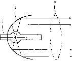
图1概要地显示一种现有的光照射装置。如图1所示,现有的光照射装置包括一灯管1、一反射罩2、灯管1发光后,借由反射罩2将灯管1发射的光束b产生准直光束或汇聚光束。FIG. 1 schematically shows a conventional light irradiation device. As shown in FIG. 1 , the existing light irradiation device includes a
在现有的光照射装置中,灯管一般使用氙气灯管或复金属卤素灯管。然而,此类灯管发光时,会产生大量的热能。进一步,为了解决现有的光照射装置发光时产生的大量热能,一般使用液态冷却装置移除热能。然而,具有液态冷却装置的光照射装置具有大体积的缺点。In the existing light irradiation device, the lamp tube generally uses a xenon lamp tube or a complex metal halide lamp tube. However, when such lamps emit light, a large amount of heat energy is generated. Further, in order to solve the large amount of heat energy generated when the existing light irradiation device emits light, a liquid cooling device is generally used to remove the heat energy. However, a light irradiation device having a liquid cooling device has a disadvantage of being bulky.
此外,氙气灯管以及复金属卤素灯管会发出广波段波长的光。然而,光照射装置使用于光动力治疗时,只需要一既定的狭窄波段波长。因此,现有的光照射装置需要滤光片消除不需要波段的波长。In addition, xenon lamps and complex metal halide lamps emit light at a broad range of wavelengths. However, when the light irradiation device is used in photodynamic therapy, it only needs a predetermined narrow band wavelength. Therefore, the conventional light irradiation device requires a filter to eliminate wavelengths in unnecessary bands.
此外,氙气灯管以及复金属卤素灯管的使用寿命大约数百小时。因此,目前使用于光动力治疗的光照射装置具有需要经常更换灯管的缺点。In addition, the service life of xenon lamps and complex metal halide lamps is about hundreds of hours. Therefore, the light irradiation device currently used for photodynamic therapy has the disadvantage of requiring frequent replacement of the lamp tube.
综合上述,使用于光动力治疗的现有光照射装置具有大体积、高热能以及昂贵等缺点。Based on the above, the existing photoirradiation devices used for photodynamic therapy have disadvantages such as large volume, high heat energy, and high cost.
发明内容Contents of the invention
有鉴于此,为了解决上述的问题,本发明提出一种光照射装置,适用于光动力治疗;其中,光照射装置使用半导体发光元件。在本发明中,使用半导体发光元件的光照射装置不会产生高热。本发明的光照射装置省略使用液态冷却装置,而利用散热器与风扇散去照射装置中的热能。In view of this, in order to solve the above problems, the present invention proposes a light irradiation device suitable for photodynamic therapy; wherein, the light irradiation device uses a semiconductor light emitting element. In the present invention, a light irradiation device using a semiconductor light emitting element does not generate high heat. The light irradiation device of the present invention omits the use of a liquid cooling device, and utilizes a radiator and a fan to dissipate heat energy in the irradiation device.
本发明的一目的在于:提供一种光照射装置,适用于光动力治疗,包括;一支撑基板、设置于上述支撑基板上的数个半导体发光元件、与上述支撑基板黏接的一散热器以及一风扇;其中,设置于上述支撑基板上的数个半导体发光元件排列成半圆球状。当半导体发光元件发光时,散热器与风扇散去该光照射装置内的热能。An object of the present invention is to provide a light irradiation device suitable for photodynamic therapy, comprising: a supporting substrate, several semiconductor light-emitting elements arranged on the supporting substrate, a radiator bonded to the supporting substrate, and A fan; wherein, several semiconductor light-emitting elements arranged on the above-mentioned support substrate are arranged in a hemispherical shape. When the semiconductor light emitting element emits light, the radiator and the fan dissipate the heat energy in the light irradiation device.
本发明的另一目的在于提供一种光照射装置,适用于光动力治疗,包括:一支撑基板、设置于上述支撑基板上的数个半导体发光元件、一正透镜、与上述支撑基板黏接的一散热器以及一风扇;其中,设置于上述支撑基板上的数个半导体发光元件发射出一准直光束,接着借由上述正透镜将上述准直光束形成一汇聚光束。当半导体发光元件发光时,散热器与风扇散去光照射装置内的热能。Another object of the present invention is to provide a light irradiation device suitable for photodynamic therapy, comprising: a supporting substrate, several semiconductor light emitting elements arranged on the supporting substrate, a positive lens, and a lens bonded to the supporting substrate. A heat sink and a fan; wherein, several semiconductor light-emitting elements arranged on the above-mentioned supporting substrate emit a collimated beam, and then the above-mentioned collimated beam is formed into a converging beam by the above-mentioned positive lens. When the semiconductor light emitting element emits light, the radiator and the fan dissipate the heat energy in the light irradiation device.
本发明的一特征在于,设置于上述支撑基板上的数个半导体发光元件排列成半圆球状。当半导体发光元件发光时,产生集中的光束。A feature of the present invention is that a plurality of semiconductor light emitting elements arranged on the above-mentioned support substrate are arranged in a hemispherical shape. When the semiconductor light-emitting element emits light, a concentrated beam of light is produced.
本发明的另一特征在于,设置于上述支撑基板上的数个半导体发光元件发射出一准直光束,接着借由上述正透镜将上述准直光束形成集中的光束。Another feature of the present invention is that several semiconductor light emitting elements disposed on the support substrate emit a collimated light beam, and then the collimated light beam is formed into a concentrated light beam by the positive lens.
本发明的再一特征在于,当半导体发光元件发光时,使用散热器与风扇散去光照射装置产生的热能。Another feature of the present invention is that when the semiconductor light-emitting element emits light, a heat sink and a fan are used to dissipate the heat energy generated by the light-irradiating device.
本发明的一优点在于,上述半导体发光元件具有较长的使用寿命。An advantage of the present invention is that the above-mentioned semiconductor light-emitting element has a long service life.
本发明的另一优点在于,不需要使用液态冷却装置,减少光照射装置的体积与重量。Another advantage of the present invention is that there is no need to use a liquid cooling device, which reduces the volume and weight of the light irradiation device.
本发明的再一优点在于,上述半导体发光元件可发射出同调性的单一波长光束。Another advantage of the present invention is that the above-mentioned semiconductor light-emitting element can emit a coherent single-wavelength light beam.
附图说明Description of drawings
为让本发明的上述目的、特征、和优点能更明显易懂,下文特举一实施例,并配合附图,详细说明如下:In order to make the above objects, features, and advantages of the present invention more comprehensible, an embodiment is specifically cited below, together with the accompanying drawings, and the detailed description is as follows:
图1是概要地显示一种现有的光照射装置;Fig. 1 schematically shows a kind of existing light irradiation device;
图2A是概要地显示使用于本发明的光照射装置的一种半导体发光元件;Fig. 2A schematically shows a semiconductor light-emitting element used in the light irradiation device of the present invention;
图2B是概要地显示使用于本发明的光照射装置的另一种半导体发光元件;Fig. 2B schematically shows another semiconductor light-emitting element used in the light irradiation device of the present invention;
图3是概要地显示本发明的第一实施例的一光照射装置;Fig. 3 schematically shows a light irradiation device of the first embodiment of the present invention;
图4是概要地显示本发明的光照射装置的光强度分布图;Fig. 4 is a diagram schematically showing the light intensity distribution of the light irradiation device of the present invention;
图5是概要地显示本发明的第一实施例的一光照射装置的另一种型态;Fig. 5 schematically shows another type of a light irradiation device of the first embodiment of the present invention;
图6是概要地显示本发明的第二实施例的一光照射装置;Fig. 6 schematically shows a light irradiation device of a second embodiment of the present invention;
图7A至图7C是分别显示本发明的光照射装置的各种范例;7A to 7C show various examples of the light irradiation device of the present invention;
图8是概要地说明PHOTOFRIN药物使用本发明的光照射装置的光动力治疗结果。Fig. 8 schematically illustrates the results of photodynamic therapy of PHOTOFRIN drug using the light irradiation device of the present invention.
具体实施方式Detailed ways
图2A是概要地显示使用于本发明的光照射装置的一种半导体发光元件。如图2A所示,一光发射二极管晶片(LED die)3设置于一杯状导电架(cup-type leadframe)4上,以及光发射二极管晶片3借由导线5与另一导电架6连接;其中,此导电架6与杯状导电架4是平行设置。此杯状导电架4与光发射二极管晶片3之间具有一导电黏接层7,且此导电黏接层7是一银层、金层、铝层或镍层等等。此外,杯状导电架4是以铜、铜合金或铁合金为材料制造的。最后,一第一封装材料8封装此光发射二极管晶片3及对导电架4、6形成一半导体发光元件。FIG. 2A schematically shows a semiconductor light emitting element used in the light irradiation device of the present invention. As shown in Figure 2A, a light-emitting diode chip (LED die) 3 is arranged on a cup-shaped conductive frame (cup-type leadframe) 4, and the light-emitting diode chip 3 is connected to another conductive frame 6 by a wire 5; wherein , the conductive frame 6 is arranged parallel to the cup-shaped conductive frame 4 . There is a conductive adhesive layer 7 between the cup-shaped conductive frame 4 and the LED chip 3, and the conductive adhesive layer 7 is a silver layer, a gold layer, an aluminum layer or a nickel layer and the like. In addition, the cup-shaped conductive frame 4 is made of copper, copper alloy or iron alloy. Finally, a first encapsulation material 8 encapsulates the light-emitting diode chip 3 and forms a semiconductor light-emitting element on the conductive frames 4 and 6 .
图2B是概要地显示使用于本发明的光照射装置的另一种半导体发光元件。如图2B所示,一光发射二极管晶片3设置于具有导电电路的一印刷电路板(prlnted circuit board简称PCB)9上,并且于PCB 9的周围形成包围光发射二极管晶片3的反射侧壁10。此外,通过一导线5将该光发射二极管晶片3与该印刷电路板9的导电电路连接。最后,一第一封装材料8封装此光发射二极管晶片3及此PCB 9形成另一半导体发光元件。FIG. 2B schematically shows another semiconductor light emitting element used in the light irradiation device of the present invention. As shown in Figure 2B, a light-emitting diode chip 3 is arranged on a printed circuit board (prlnted circuit board referred to as PCB) 9 with a conductive circuit, and a reflective side wall 10 surrounding the light-emitting diode chip 3 is formed around the PCB 9 . Furthermore, the LED chip 3 is connected to the conductive circuit of the printed circuit board 9 via a wire 5 . Finally, a first encapsulation material 8 encapsulates the light-emitting diode chip 3 and the PCB 9 to form another semiconductor light-emitting element.
第一实施例first embodiment
图3是概要地显示本发明的第一实施例的一光照射装置。如图3所示,一支撑基板21大体为一半圆球状,且数个半导体发光元件20设置于此支撑基板21上。因此,数个半导体发光元件20集中地朝向半圆球状的支撑基板21的圆心发射光束,且此光束具有一汇聚区域22。FIG. 3 schematically shows a light irradiation device according to a first embodiment of the present invention. As shown in FIG. 3 , a supporting
参考图3,通过一热导胶(thermal conductive paste)23将支撑基板21与一散热器24黏接。一风扇25与散热器24彼此对立地设置。当光照射装置发光时,通过风扇25与散热器24散去数个半导体发光元件20产生的热能。Referring to FIG. 3 , the
参考图3,于本发明的第一实施例中,应用于光动力治疗的光照射装置包括一光导管26,例如一光纤,其一端设置于光束产生的汇聚区域22。因此,当数个半导体发光元件20发光时,大部分的光通过光导管26传递至需要光动力治疗的部位。Referring to FIG. 3 , in the first embodiment of the present invention, the light irradiation device applied to photodynamic therapy includes a
图4是概要地显示本发明的光照射装置的光强度分布图。如图4所示,随着光导管的一端远离光轴位置。光导管发射的光强度逐渐减少。此外,随着光导管的一端与光源距离增加,光导管发射的光强度亦逐渐减少。于本发明的第一实施例中,应用于光动力治疗的光照射装置通过光导管发射出216.9mW/cm2的光强度。Fig. 4 is a diagram schematically showing the light intensity distribution of the light irradiation device of the present invention. As shown in Figure 4, as one end of the light guide is farther away from the optical axis. The light intensity emitted by the light guide gradually decreases. In addition, as the distance between one end of the light guide and the light source increases, the light intensity emitted by the light guide decreases gradually. In the first embodiment of the present invention, the light irradiation device applied to photodynamic therapy emits a light intensity of 216.9 mW/cm2 through the light guide.
图5是概要地显示本发明的第一实施例的一光照射装置的另一种型态。于本发明的第一实施例的支撑基板21可以选择弹性物质、半弹性物质或硬质材料,例如陶瓷、聚合物质或金属材料制造。当支撑基板21选择硬质材料,例如陶瓷,参考图3,数个支撑基板21a、21b、21c构成半圆球状的结构。当支撑材料选择弹性物质,例如聚合物质,参考图5,支撑基板21变形形成半圆球状的结构。FIG. 5 schematically shows another form of a light irradiation device according to the first embodiment of the present invention. The
第二实施例second embodiment
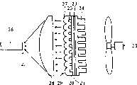
图6是概要地显示本发明的第二实施例的一光照射装置。如图6所示,数个半导体发光元件20形成于平面的一支撑基板21上;其中,每一半导体发光元件20发射出大体准直的光束。于本发明的第二实施倒中,光照射装置更包括一正透镜28。当数个半导体发光元件20发射准直光束后,通过正透镜28将上述准直光束集中且形成一汇聚区域22。FIG. 6 schematically shows a light irradiation device according to a second embodiment of the present invention. As shown in FIG. 6 , several semiconductor
参考图6,通过一热导胶(thermal conductive paste)23将支撑基板21与一散热器24黏接。接着,一风扇25与散热器24彼此对立地设置。当光照射装置发光时,通过风扇25与散热器24散去数个半导体发光元件20产生的热能。Referring to FIG. 6 , the
参考图6,于本发明的第一实施例中,应用于光动力治疗的光照射装置更包括一光导管26,例如一光纤,其一端设置于正透镜28将准直光束形成一汇聚区域22。因此,当数个半导体发光元件20发光时,大部分的光通过光导管26传递至需要光动力治疗的部位。Referring to FIG. 6, in the first embodiment of the present invention, the light irradiation device applied to photodynamic therapy further includes a
于本发明的第一实施例与第二实施例中,数个半导体发光元件20设置于支撑基板21后,再通过第二封装材料27将数个半导体发光元件20与支撑基板21封装。于本发明的第二实施例中,第二封装材料27具有微透镜阵列(micro-lens array)结构29,将数个半导体发光元件20发射的光束转换成较准直的光束。In the first embodiment and the second embodiment of the present invention, after a plurality of semiconductor
图7A至图7C是分别显示本发明的光照射装置的各种范例。如图7A所示,于本发明的光照射装置100中,光导管26具有固定直径。如图7B所示,于本发明的光照射装置100中,光导管26的另一端具有逐渐变细的结构30。图7B所示的光导管发射的光束较图7A所示的光导管发射的光束的截面积更小。7A to 7C respectively show various examples of the light irradiation device of the present invention. As shown in FIG. 7A , in the
此外,于图7A与图7B中,一直流电源供应器31设置于本发明的光照射装置100中。参考图7C,本发明的光照射装置100更可以使用一交流直流转换电源供应器32。因此,通过建筑物的插座为本发明的光照射装置提供电源。In addition, in FIGS. 7A and 7B , a
图8是概要地说明PHOTOFRIN药物使用本发明的光照射装置的光动力治疗结果;其中,本发明的光照射装置的发光波长为630nm。参考图8,横座标是表示本发明的光照射装置照射PHOTORIN药物的时间,而纵座标是表示具有PHOTOFRIN药物的细胞被本发明的光照射装置照射后的存活率。如图8所示,本发明的光照射装置照射具有PHOTOFRIN药物的细胞后,确实可降低此细胞的存活率。Fig. 8 is a schematic illustration of the photodynamic therapy results of PHOTOFRIN drug using the light irradiation device of the present invention; wherein, the light emission wavelength of the light irradiation device of the present invention is 630nm. Referring to FIG. 8, the abscissa represents the time when the photoirradiation device of the present invention irradiates the PHOTORIN drug, and the ordinate represents the survival rate of cells having PHOTOFRIN drug after being irradiated by the photoirradiation device of the present invention. As shown in FIG. 8 , after the photoirradiation device of the present invention irradiates cells with PHOTOFRIN drug, the survival rate of the cells can indeed be reduced.
在本发明中,由于不同药物对于不同波长的反应,因此本发明的光照射装置内可设置不同波长的光发射二极管晶片。In the present invention, since different drugs respond to different wavelengths, light-emitting diode chips with different wavelengths can be arranged in the light irradiation device of the present invention.
虽然本发明已以一较佳实施例揭露如上,然而其并非用以限定本发明,任何熟悉此领域的技术人员,在不脱离本发明的精神和范围,当可作些更动与润饰,因此本发明的保护范围以权利要求所确定的范围为准。Although the present invention has been disclosed as above with a preferred embodiment, it is not intended to limit the present invention. Any person skilled in the art may make some changes and modifications without departing from the spirit and scope of the present invention. Therefore The protection scope of the present invention shall be determined by the claims.
Claims (24)
Priority Applications (1)
| Application Number | Priority Date | Filing Date | Title |
|---|---|---|---|
| CN 01130240CN1267169C (en) | 2001-12-29 | 2001-12-29 | Light irradiation device for photodynamic therapy |
Applications Claiming Priority (1)
| Application Number | Priority Date | Filing Date | Title |
|---|---|---|---|
| CN 01130240CN1267169C (en) | 2001-12-29 | 2001-12-29 | Light irradiation device for photodynamic therapy |
Publications (2)
| Publication Number | Publication Date |
|---|---|
| CN1429636Atrue CN1429636A (en) | 2003-07-16 |
| CN1267169C CN1267169C (en) | 2006-08-02 |
Family
ID=4669838
Family Applications (1)
| Application Number | Title | Priority Date | Filing Date |
|---|---|---|---|
| CN 01130240Expired - Fee RelatedCN1267169C (en) | 2001-12-29 | 2001-12-29 | Light irradiation device for photodynamic therapy |
Country Status (1)
| Country | Link |
|---|---|
| CN (1) | CN1267169C (en) |
Cited By (1)
| Publication number | Priority date | Publication date | Assignee | Title |
|---|---|---|---|---|
| WO2009030109A1 (en)* | 2007-08-28 | 2009-03-12 | Shyh Liang Lou | An induction device for photodynamic therapy and diagnosis |
- 2001
- 2001-12-29CNCN 01130240patent/CN1267169C/ennot_activeExpired - Fee Related
Cited By (1)
| Publication number | Priority date | Publication date | Assignee | Title |
|---|---|---|---|---|
| WO2009030109A1 (en)* | 2007-08-28 | 2009-03-12 | Shyh Liang Lou | An induction device for photodynamic therapy and diagnosis |
Also Published As
| Publication number | Publication date |
|---|---|
| CN1267169C (en) | 2006-08-02 |
Similar Documents
| Publication | Publication Date | Title |
|---|---|---|
| CN206563190U (en) | LED filament and LED bulb lamp using same | |
| US7863641B2 (en) | Method and apparatus for using light emitting diodes for the treatment of biological tissue | |
| CN2811736Y (en) | High power LED lighting device with high heat radiation efficiency | |
| US9360167B2 (en) | LED module and LED lamp employing same | |
| CN1840958B (en) | System-in-package high-power high-efficiency diode bulb | |
| US11268659B2 (en) | Lighting apparatus | |
| CN102160203B (en) | Lighting module | |
| US20050116235A1 (en) | Illumination assembly | |
| JP6206795B2 (en) | Light emitting module and lighting device | |
| JP2012503331A (en) | Lighting module | |
| CN1487605A (en) | light emitting device | |
| CN102160202A (en) | Optical disk for lighting module | |
| JP2012503335A (en) | Optical cup for lighting module | |
| WO2008058446A1 (en) | Light emitting system | |
| CN105529390B (en) | A kind of integrated UVLED modules of the Self-concentration of inorganic encapsulated | |
| US20110122630A1 (en) | Solid State Lamp Having Vapor Chamber | |
| JP5898881B2 (en) | Lighting device | |
| CN102980077A (en) | A tubular structure LED integrated light source | |
| CN103427010B (en) | Ultraviolet lamp and Ultraviolet radiation head | |
| CN1267169C (en) | Light irradiation device for photodynamic therapy | |
| JP2011138777A (en) | Lighting system | |
| CN108461613A (en) | A kind of UV-LED light sources and its lamps and lanterns | |
| CN103633235A (en) | LED module and manufacturing process thereof | |
| CN102954378A (en) | High optical power density light-emitting diode (LED) light source module | |
| KR20120065827A (en) | Transparent led chip package and led light comprising the same |
Legal Events
| Date | Code | Title | Description |
|---|---|---|---|
| C10 | Entry into substantive examination | ||
| SE01 | Entry into force of request for substantive examination | ||
| C06 | Publication | ||
| PB01 | Publication | ||
| C10 | Entry into substantive examination | ||
| SE01 | Entry into force of request for substantive examination | ||
| C14 | Grant of patent or utility model | ||
| GR01 | Patent grant | ||
| CF01 | Termination of patent right due to non-payment of annual fee | Granted publication date:20060802 Termination date:20151229 | |
| EXPY | Termination of patent right or utility model |