CN1429152A - Fluid Applicator - Google Patents
Fluid ApplicatorDownload PDFInfo
- Publication number
- CN1429152A CN1429152ACN01809541ACN01809541ACN1429152ACN 1429152 ACN1429152 ACN 1429152ACN 01809541 ACN01809541 ACN 01809541ACN 01809541 ACN01809541 ACN 01809541ACN 1429152 ACN1429152 ACN 1429152A
- Authority
- CN
- China
- Prior art keywords
- tool
- fluid
- cartridge
- tip
- container
- Prior art date
- Legal status (The legal status is an assumption and is not a legal conclusion. Google has not performed a legal analysis and makes no representation as to the accuracy of the status listed.)
- Granted
Links
Images


Classifications
- B—PERFORMING OPERATIONS; TRANSPORTING
- B43—WRITING OR DRAWING IMPLEMENTS; BUREAU ACCESSORIES
- B43K—IMPLEMENTS FOR WRITING OR DRAWING
- B43K5/00—Pens with ink reservoirs in holders, e.g. fountain-pens
- B43K5/18—Arrangements for feeding the ink to the nibs
- B43K5/1818—Mechanical feeding means, e.g. valves; Pumps
- B43K5/189—Pumps
- B—PERFORMING OPERATIONS; TRANSPORTING
- B43—WRITING OR DRAWING IMPLEMENTS; BUREAU ACCESSORIES
- B43K—IMPLEMENTS FOR WRITING OR DRAWING
- B43K11/00—Filling devices
- B43K11/005—Filling devices for refilling capillary reservoirs
- B—PERFORMING OPERATIONS; TRANSPORTING
- B43—WRITING OR DRAWING IMPLEMENTS; BUREAU ACCESSORIES
- B43K—IMPLEMENTS FOR WRITING OR DRAWING
- B43K5/00—Pens with ink reservoirs in holders, e.g. fountain-pens
- B43K5/18—Arrangements for feeding the ink to the nibs
- B—PERFORMING OPERATIONS; TRANSPORTING
- B43—WRITING OR DRAWING IMPLEMENTS; BUREAU ACCESSORIES
- B43K—IMPLEMENTS FOR WRITING OR DRAWING
- B43K5/00—Pens with ink reservoirs in holders, e.g. fountain-pens
- B43K5/18—Arrangements for feeding the ink to the nibs
- B43K5/1818—Mechanical feeding means, e.g. valves; Pumps
- B43K5/1827—Valves
- B43K5/1836—Valves automatically closing
- B43K5/1863—Valves automatically closing opened by actuation of the rear-side of the pen
- B43K5/1872—Valves automatically closing opened by actuation of the rear-side of the pen mounted on ink-cartridges
- B—PERFORMING OPERATIONS; TRANSPORTING
- B43—WRITING OR DRAWING IMPLEMENTS; BUREAU ACCESSORIES
- B43K—IMPLEMENTS FOR WRITING OR DRAWING
- B43K8/00—Pens with writing-points other than nibs or balls
- B43K8/02—Pens with writing-points other than nibs or balls with writing-points comprising fibres, felt, or similar porous or capillary material
Landscapes
- Engineering & Computer Science (AREA)
- Mechanical Engineering (AREA)
- Containers And Packaging Bodies Having A Special Means To Remove Contents (AREA)
- Coating Apparatus (AREA)
- Pens And Brushes (AREA)
- Media Introduction/Drainage Providing Device (AREA)
- Materials For Medical Uses (AREA)
- Closures For Containers (AREA)
Abstract
Translated fromChinese
Description
Translated fromChinese本发明涉及一种工具,及优选地是一用以将流体涂抹至表面的标记工具,并且特别涉及一书写笔,包含记号笔或刷子、特别是艺术家的刷子,但是非专用于此。亦考虑到其他刷子型式,例如那些用以清洁牙齿或者将漱口药水或香水涂抹至牙齿的刷子。The present invention relates to an implement, and preferably a marking implement for applying a fluid to a surface, and in particular to a writing pen, including a marker or a brush, especially but not exclusively an artist's brush. Other brush types are also contemplated, such as those used to clean teeth or apply mouthwash or perfume to teeth.
已知很多用于各种应用的学校或办公室用的不同型式的笔、绘画刷子及标记器。此工具可在套管中包含一吸收性毛毡,该套管中装有例如墨水的流体,且该流体由于重力流至该工具的尖端。因此,当该工具储存有最上面的该尖端时,该流体由该处流出,并且通常因误信其中的所有墨水已用尽而丢弃此工具,而用力摇动该工具将导致该流体再次流至该尖端。其他工具有可替换的筒,其再次依靠重力使其内容物流至该工具尖端。特别是儿童们所使用的绘画刷子可能难以使用。Many different types of pens, paint brushes and markers for school or office use are known for various applications. The tool may contain an absorbent felt in a sleeve that contains a fluid, such as ink, that flows by gravity to the tip of the tool. Thus, when the tool is stored with the tip uppermost, the fluid exits there, and the tool is usually discarded in the false belief that all ink therein has been used up, and shaking the tool vigorously will cause the fluid to flow again to The tip. Other tools have replaceable cartridges, which again rely on gravity to flow their contents to the tip of the tool. Paint brushes, especially those used by children, can be difficult to use.
本发明的一目的是提供用于将流体涂抹至一表面的工具,例如标记工具,其克服或至少减轻一些与已知流体涂抹工具有关的问题。It is an object of the present invention to provide implements for applying fluid to a surface, such as marking implements, which overcome or at least alleviate some of the problems associated with known fluid application implements.
按照本发明的一方面,已提供一种用于将流体涂抹至一表面的工具,优选地是一标记工具,其包括一流体涂抹尖端;一用于该尖端的保持器;一安装在该保持器内或可连接至该保持器的含有将涂抹的流体的筒,该流体优选地是一液体,例如墨水、颜料或漱口药水、牙齿用香水或清洁剂;以及一可手动操作的喷射泵结构,其用于通过手动压力从该筒重复地配送一预定量的流体至该工具的尖端。According to one aspect of the present invention, there is provided a tool for applying fluid to a surface, preferably a marking tool, comprising a fluid application tip; a holder for the tip; a holder mounted on the holder a cartridge containing a fluid to be applied, preferably a liquid such as ink, paint or mouthwash, dental perfume or cleaner, within the holder or connectable to the holder; and a manually operable jet pump Structure for repeatedly dispensing a predetermined amount of fluid from the barrel to the tip of the tool by manual pressure.
该保持器优选地是可包括一用于该筒的套管及一用于该尖端的外壳,它们装配在一起成为一独立单元,或该保持器可以是一连接到该筒的尖端外壳。因此,本发明的工具具有一优点,即其设置有一可替换的或可再充填的筒,由此当其内流体已用尽时,避免浪费地丢弃用于该筒的套管及该尖端,随同该工具的任何其他部件,例如用于该尖端的外壳。The holder may preferably comprise a sleeve for the barrel and a housing for the tip which fit together as a self-contained unit, or the holder may be a tip housing attached to the barrel. Thus, the tool of the present invention has the advantage that it is provided with a replaceable or refillable cartridge, thereby avoiding wasteful disposal of the sleeve and the tip for the cartridge when the fluid in it has been exhausted, Any other parts that accompany the tool, such as the housing for the tip.
本发明的工具具有另外的优点,即其设置有一可手动操作的喷射泵结构,该喷射泵能吸取该筒中的流体,以便在压力下确实地引导该流体至该工具尖端,而不须对用于该流体的任何容器加压。再者,布置该喷射泵以根据该喷射泵的容量而在每次操作时提供一预定流体量,由此避免该泵结构的连续操作导致用尽该筒的全部内容物和/或由该工具尖端溢出流体的可能性。The tool of the present invention has the additional advantage that it is provided with a manually operable jet pump arrangement which draws fluid in the barrel to positively direct the fluid under pressure to the tool tip without requiring any manipulation of the tool. Pressurize any container of this fluid. Furthermore, the jet pump is arranged to provide a predetermined amount of fluid at each operation according to the capacity of the jet pump, thereby avoiding continuous operation of the pump structure leading to exhaustion of the entire contents of the cartridge and/or loss of fluid by the tool. Possibility of tip spilling fluid.
用于本发明工具的喷射泵结构可为任何用于重复地配送一预定、已计量流体量的合适设计。例如在配送香水中此泵是熟知的。合适泵结构的细节是只通过举例揭示在以下的专利公开文本中,其全部内容是以引用的方式并入本文中作为参考:EP-0126175、US-A-3774849、US-A-4029261、GB-B2252941、EP-A-0930102以及FR-A-2402388。如此,总而言之,该泵的操作需要一最初的行程以从其主体排出空气,以致随后的放开动作将从储存器吸入流体,这是未加压的作用。随后的操作则将经过一运送管配送来自该准备好的泵的流体,用作一次喷射,以及随后的放开则将以来自该储存器的新鲜流体量充装该泵。一般为产生一次喷射,使一喷嘴位于该运送管的出口,但为本发明的目的,通常不需要此喷嘴。The jet pump configuration for the implements of the present invention may be of any suitable design for repeatedly dispensing a predetermined, metered amount of fluid. Such pumps are well known, for example, in dispensing perfumes. Details of suitable pump constructions are disclosed by way of example only in the following patent publications, the entire contents of which are incorporated herein by reference: EP-0126175, US-A-3774849, US-A-4029261, GB - B2252941, EP-A-0930102 and FR-A-2402388. Thus, in summary, the operation of the pump requires an initial stroke to expel air from its body, so that a subsequent release action will draw fluid from the reservoir, which is an unpressurized effect. Subsequent operations would dispense fluid from the primed pump through a delivery tube for one shot, and subsequent releases would prime the pump with a fresh volume of fluid from the reservoir. Typically a nozzle is located at the outlet of the delivery tube to produce a spray, but for the purposes of the present invention this nozzle is generally not required.
本发明的工具将呈有利的细长构形,以及一般将呈笔或标记器、特别是白板标记器或者用于书写或绘画的刷子的形式。该流体通常将是液体,以及可为任何所需颜色的墨水或颜料。包含漱口药水的有香味的或清洁的溶液或分散剂可与本发明的牙刷一起使用。The implement of the invention will be of advantageous elongate configuration and will generally be in the form of a pen or marker, especially a whiteboard marker, or a brush for writing or drawing. The fluid will generally be a liquid, and may be ink or paint of any desired colour. Scented or cleansing solutions or dispersions comprising mouthwashes may be used with the toothbrushes of the present invention.
在优选具体实施例中,该泵结构是朝向该套管的一端部纵向地设置在该工具的尖端附近,以及该筒由该处延伸离开并可在该套管的另一端部进出,使得在该另一端部纵向地施加在该筒上的手动压力可有效地操作该泵结构。In a preferred embodiment, the pump structure is disposed longitudinally towards one end of the cannula near the tip of the tool, and the barrel extends away from there and is accessible at the other end of the cannula such that in Manual pressure exerted by the other end longitudinally on the barrel is effective to operate the pump arrangement.
该泵结构或至少其一部件可纵向地固定在该筒套管内,使得该筒可在其内纵向地移动。在一优选构形中,该泵结构的出口喷嘴是固定地紧固到该套管内,以及包含例如泵主体、入口及出口的泵结构的剩余部件可随同该筒一起移动而作为一独立单元。The pump structure, or at least a component thereof, may be fixed longitudinally within the cartridge casing such that the cartridge may move longitudinally therein. In a preferred configuration, the outlet nozzle of the pump structure is fixedly secured within the sleeve and the remainder of the pump structure including eg the pump body, inlet and outlet is movable with the cartridge as a self-contained unit.
在另外一个实施例中,工具和例如特别是该筒套管布置成这样,即,施加在其上的横向向内的手动压力能使该筒和泵结构或它们的部件彼此相对纵向移动,由此影响所述液体的配送。向内的压力由一可滑动部件提供,该部件具有向工具的纵向轴线倾斜的表面以与泵结构的配合表面配合工作,并因此影响所述相对纵向移动。In another embodiment, the tool and, for example, in particular the cartridge sleeve, are arranged such that laterally inward manual pressure applied thereon can move the cartridge and pump structure or parts thereof longitudinally relative to each other, by This affects the delivery of the liquid. The inward pressure is provided by a slidable member having surfaces inclined towards the longitudinal axis of the tool to co-operate with mating surfaces of the pump structure and thereby effect said relative longitudinal movement.
在再一个实施例中,工具的两部分的相对转动有效地操作该泵结构。应该了解,这样的旋转可以转换为泵结构和该筒之间的相对纵向移动。In yet another embodiment, relative rotation of the two parts of the tool effectively operates the pump structure. It should be appreciated that such rotation may translate into relative longitudinal movement between the pump structure and the cartridge.
还应该清楚的是,泵结构可由工具尖端操作,通过尖端上的手动压力引起其必须的纵向移动。It should also be clear that the pump structure can be operated by the tool tip, causing its necessary longitudinal movement by manual pressure on the tip.
本发明的工具在该筒及该尖端之间可具有一中间腔室,该腔室可具有一外部视窗,以致使用者可确定该泵的下一次操作是否将导致流体配送至该尖端,或在其他方面有效地充满该中间腔室,以及需要该泵结构的一随后操作从该腔室配送该流体至该工具的尖端。The tool of the present invention may have an intermediate chamber between the barrel and the tip, which may have an external viewing window so that the user can determine whether the next operation of the pump will result in fluid being dispensed to the tip, or whether Others effectively fill the intermediate chamber and require a subsequent operation of the pump structure to dispense the fluid from the chamber to the tip of the tool.
该尖端本身一般只具有一小的流体容量,以及因此连接至一在该尖端外壳中的流体储存器,例如一块毛毡或泡沫塑料材料。该泵结构可包含一位于其出口的喷嘴,以帮助分布将配送至该尖端储存器的流体。The tip itself typically has only a small fluid capacity, and is therefore connected to a fluid reservoir, such as a piece of felt or foam, in the tip housing. The pump structure may include a nozzle at its outlet to help distribute the fluid to be delivered to the tip reservoir.
在该泵结构上的手动压力最初将直接或间接地由该处排除空气,及随后的放开则有效地将流体吸入该泵。该泵结构的一随后操作则配送来自该泵的预定的已准备好的流体量,且后续的压力将不会导致配送任何更多的流体。当该液体容器是坚硬的时,则必须以空气取代所配送的液体。该补充的空气是经由一在该喷射泵如一常规喷射泵中的合适开口吸入。例如当倒置该工具时,假如需要防止流体经由该空气开口泄漏,则可使用例如球阀的阀门。在该液体容器不坚硬,但像气球般很柔软的情况下,则不需要将进入的补充空气,且不需要阀门。Manual pressure on the pump structure will initially expel air from there, directly or indirectly, and subsequent release will effectively draw fluid into the pump. A subsequent operation of the pump arrangement then dispenses the predetermined ready volume of fluid from the pump, and subsequent pressures will not result in any more fluid being dispensed. When the liquid container is rigid, it is necessary to replace the dispensed liquid with air. The supplemental air is drawn in through a suitable opening in the jet pump, such as a conventional jet pump. If it is desired to prevent fluid leakage through the air opening, eg when the tool is inverted, a valve such as a ball valve may be used. Where the liquid container is not rigid, but is soft like a balloon, no make-up air will be required and no valves will be required.
按照本发明的另一方面,已为用于将流体涂抹至一表面的工具提供一组件,优选地是一标记工具组件,其包括含有将涂抹的流体的一次性的或可再充填的筒;以及与该筒可操作地关联、优选固定地安装在其上面的一可手动操作的喷射泵结构,用于在压力下从该筒重复地配送一预定流体量。According to another aspect of the present invention, there is provided an assembly for a tool for applying a fluid to a surface, preferably a marking tool assembly, comprising a disposable or refillable cartridge containing the fluid to be applied; and a manually operable jet pump structure operably associated with, preferably fixedly mounted on, the cartridge for repeatedly dispensing a predetermined amount of fluid under pressure from the cartridge.
按照本发明的再一方面,已为本发明的组件及工具提供一次性的或可再充填的筒。According to a further aspect of the present invention, disposable or refillable cartridges have been provided for the assemblies and tools of the present invention.
本发明对于配送相对少量例如0.001-5毫升或更多的流体特别有用,且特别用于一标记工具,但非专用于此。The present invention is particularly useful for dispensing relatively small amounts of fluid, eg, 0.001-5 ml or more, and is particularly useful for a marking tool, but not exclusively.
该可更换或可再充填的筒优选地包含一适用于本发明工具的容器,该容器包括一初级储存器,其用于保持将涂抹的流体及在一端部具有一出口;一流体供给管,其位于该初级储存器内,在使用时,该供给管在一端部连接至该出口以及在其另一端部具有次级储存器,其中当该容器位于第一方位时,一已测量剂量的该标记流体可进入该次级储存器,以及其中当该容器倒置时,该次级储存器将保持用于配送的流体剂量,且其余流体将通过重力移至该容器内的另一位置并被保留住。The replaceable or refillable cartridge preferably comprises a container suitable for use with the tool of the present invention, the container comprising a primary reservoir for holding fluid to be applied and having an outlet at one end; a fluid supply tube, It is located within the primary reservoir, and in use, the supply tube is connected at one end to the outlet and has a secondary reservoir at its other end, wherein a measured dose of the Marking fluid can enter the secondary reservoir, and wherein when the container is inverted, the secondary reservoir will hold a dose of fluid for dispensing and the remaining fluid will move by gravity to another location within the container and be retained live.
当在该颠倒位置时,可通过使用一可手动操作的喷射泵、一弹簧加载式阀门机构或通过挤压该外部容器而经过该供给管运送该次级储存器中的流体。然后继续重复的压力将不会导致配送任何更多的流体。所有这些变化以如在此所使用的通用词句″喷射泵结构″所涵盖,不论排出该运送管的流体是否呈喷射形式。When in the inverted position, the fluid in the secondary reservoir can be conveyed through the supply tube by using a manually operable injection pump, a spring loaded valve mechanism or by squeezing the outer container. Continued repeated pressures will then not cause any more fluid to be dispensed. All such variations are encompassed by the general phrase "jet pump configuration" as used herein, whether or not the fluid exiting the delivery tube is in the form of a jet.
为使用此一容器更换部件,该工具可包含一用于该更换部件的喷射泵结构的作动器以及一毛细管,该毛细管进入该工具的尖端储存器内侧,作为一独立单元,而紧紧地固定在该工具上。To use such a container replacement part, the tool may include an actuator for the jet pump structure of the replacement part and a capillary that enters the inside of the tip reservoir of the tool as a self-contained unit that fits tightly fixed on the tool.
该流体优选地具有相当低的粘度以及不包含任何大的颗粒,以致来自该喷射泵结构的流体喷射不需要过度的手动压力,且该运送管出口不会轻易阻塞。在使用之前,该再充填的筒是在其开口上方覆盖著一隔膜,该隔膜连接至该供给管,可通过该作动器上的一尖锐点刺穿该隔膜,以便只允许保持在该次级储存器中的流体通过。The fluid preferably has a relatively low viscosity and does not contain any large particles so that fluid injection from the injection pump structure does not require excessive manual pressure and the delivery tube outlet does not clog easily. Before use, the refill cartridge is covered over its opening with a septum connected to the supply tube which can be pierced by a sharp point on the actuator to allow only the The fluid in the stage storage passes through.
现在将参考附图以实例叙述按照本发明的每一流体涂抹工具、工具组件、可替换的筒及可再充填的容器的一些具体实施例,其中:Some specific embodiments of each fluid application implement, implement assembly, replaceable cartridge and refillable container according to the present invention will now be described by way of example with reference to the accompanying drawings, wherein:
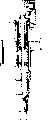
图1是经过一记号笔的第一具体实施例的剖面图;Fig. 1 is a cross-sectional view of a first embodiment of a marking pen;
图2是经过图1的笔盖的一局部剖面图,所示笔盖是位于用作该笔的按钮的一位置中;Figure 2 is a partial cross-sectional view through the pen cap of Figure 1, shown in a position serving as a button for the pen;
图3是经过图1的笔的另一剖面图,其显示该尖端及该泵外壳;Figure 3 is another cross-sectional view through the pen of Figure 1 showing the tip and the pump housing;
图4a及4b分别是图1笔的泵结构的正视图及平面图;Fig. 4a and 4b are respectively the front view and the plan view of the pump structure of Fig. 1 pen;
图4c是可用于图1工具的常规手动喷射泵结构的实例的正视图;Figure 4c is a front view of an example of a conventional hand jet pump configuration that may be used with the tool of Figure 1;
图5是图1工具的套管的一剖面图;Figure 5 is a cross-sectional view of the sleeve of the tool of Figure 1;
图6是图1工具的流体筒的一剖面图;Figure 6 is a cross-sectional view of the fluid cartridge of the tool of Figure 1;
图7a及7b分别是用于图5套管的内盖的剖面图及平面图;Figures 7a and 7b are a sectional view and a plan view, respectively, of the inner cover for the sleeve of Figure 5;
图8a及8b分别是用于图7a及7b盖子的扣环的剖面图及平面图;Figures 8a and 8b are cross-sectional and plan views, respectively, of the buckle for the lid of Figures 7a and 7b;
图9是通过标记笔的第二实施例的剖面图,其中泵结构处于关闭位置;Figure 9 is a cross-sectional view through the second embodiment of the marker pen with the pump structure in the closed position;
图10表示图9所示标记工具绕其纵向轴线旋转90度后的局部剖视图,表示的泵结构处于打开位置;Figure 10 shows a partial cross-sectional view of the marking tool shown in Figure 9 rotated 90 degrees about its longitudinal axis, showing the pump structure in the open position;
图11表示标记笔的第三实施例的正视剖面图,表示泵结构处于关闭位置;Figure 11 shows a front sectional view of a third embodiment of a marker pen showing the pump structure in a closed position;
图12表示图11所示工具的的局部剖视图,绕其纵向轴线旋转了90度;Figure 12 shows a partial cross-sectional view of the tool shown in Figure 11, rotated 90 degrees about its longitudinal axis;
图13和13a是图11和12所示工具的尖端和泵结构分别旋转90度的剖视图和正视图;Figures 13 and 13a are cross-sectional and front views, respectively, of the tip and pump structure of the tool shown in Figures 11 and 12 rotated 90 degrees;
图14和14a是图11和12所示的工具的尖端外壳的外部正视图;图14a包括了工具尖端的毛毡块;Figures 14 and 14a are external elevational views of the tip housing of the tool shown in Figures 11 and 12; Figure 14a includes a felt block for the tool tip;
图15表示标记笔的第四实施例的局部剖视图;Figure 15 shows a partial cross-sectional view of a fourth embodiment of a marking pen;
图15a表示图15中笔帽的局部剖视图,其处于可作为笔的按钮的位置上;Figure 15a shows a partial cross-sectional view of the pen cap in Figure 15, which is in a position that can be used as a button of the pen;
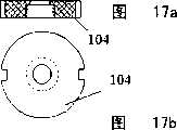
图16表示图15所示笔的尖端和泵外壳的局部剖视图;Figure 16 shows a partial cross-sectional view of the tip of the pen shown in Figure 15 and the pump housing;
图17a和17b分别是用于图15和图16所示笔的泵结构的保持部件的剖视图和平面图;Figures 17a and 17b are cross-sectional and plan views, respectively, of a retaining member for the pump structure of the pen shown in Figures 15 and 16;
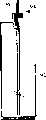
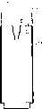
图18表示图15所示的筒和泵结构的整体组件的局部正视图;Figure 18 shows a partial front view of the overall assembly of the cartridge and pump structure shown in Figure 15;
图19表示书写工具的第五实施例的局部剖视正视图,其为刷子形式,所示的其盖处于可作为刷子按钮的位置;Figure 19 shows a partial cutaway front view of a fifth embodiment of a writing instrument in the form of a brush with its cover shown in a position that can serve as a brush button;
图19a表示了图19中刷子的盖;Figure 19a shows the cover of the brush in Figure 19;
图20a和20b分别为图19所示刷子的泵结构保持部件的剖视图和正视图;20a and 20b are respectively a sectional view and a front view of the pump structure holding part of the brush shown in FIG. 19;
图21表示图19所示刷子的筒的局部剖视正视图;Figure 21 shows a partial cutaway front view of the barrel of the brush shown in Figure 19;
图22表示标记工具的第六实施例的正视图;Figure 22 shows a front view of a sixth embodiment of a marking tool;
图23表示呈牙刷形式的工具的局部剖视正视图;Figure 23 shows a partial cutaway front view of an implement in the form of a toothbrush;
图23a表示图23所示牙刷的不同端部配装件的正视图;Figure 23a shows a front view of a different end fitting for the toothbrush shown in Figure 23;
图24表示本发明带有次级储存器的可替换的筒更换部件的剖视图,以及表示了沿线II-II的横断面以下的剖视图;Figure 24 shows a cross-sectional view of the replaceable cartridge replacement part of the present invention with a secondary reservoir, and shows a cross-sectional view below the cross-section along line II-II;
图25表示了图24所示可替换的筒更换部件在使用中处于其正常位置,而流体进入次级储存器;Figure 25 shows the replaceable cartridge replacement part shown in Figure 24 in use in its normal position with fluid entering the secondary reservoir;
图25a表示了图24所示可替换的筒更换部件在使用时旋转180度而处于其倒置位置,此时次级储存器保持了一定量的墨水;Figure 25a shows the replaceable cartridge replacement unit shown in Figure 24 rotated 180 degrees in use in its inverted position with the secondary reservoir holding a certain amount of ink;
图25b表示了图24所示的可替换的筒和内部次级储存器的第二实施例的局部剖视图;Figure 25b shows a partial cross-sectional view of a second embodiment of the alternative cartridge and internal secondary reservoir shown in Figure 24;
图25c表示的剖视图显示了图24所示的筒的第三实施例处于其倒置位置,以及一小块吸收性材料如海绵或毛毡作为次级储存器;Figure 25c represents a cross-sectional view showing the third embodiment of the cartridge shown in Figure 24 in its inverted position, and a small piece of absorbent material such as a sponge or felt as a secondary reservoir;
图26表示图24至25c中表示的可替换的筒的正视图,以及一手动操作的喷射泵结构;Figure 26 shows a front view of the alternative cartridge shown in Figures 24 to 25c, together with a manually operated jet pump arrangement;
图27表示图26所示的可替换的筒插入本发明的标记笔内的剖视图;Figure 27 shows a cross-sectional view of the replaceable cartridge shown in Figure 26 inserted into the marker pen of the present invention;
图28表示配送容器及可手动操作的喷射泵结构的分解正视图,其用作本发明工具的一更换部件;Figure 28 shows an exploded front view of the structure of the dispensing container and manually operable spray pump, which is used as a replacement part of the tool of the present invention;
图29表示图28所示的配送容器位于使流体进入该次级储存器的其正常位置的局部剖视图;Figure 29 shows a partial cross-sectional view of the dispensing container shown in Figure 28 in its normal position for fluid to enter the secondary reservoir;
图29a表示图29的配送容器在其倒置位置的局部剖视图;Figure 29a shows a partial cross-sectional view of the dispensing container of Figure 29 in its inverted position;
图30表示端盖及具有整体式毛细管的作动器的剖视图,其为图31所示记号笔的一部分;Figure 30 shows a cross-sectional view of the end cap and actuator with integral capillary, which is part of the marker pen shown in Figure 31;
图31表示可再充填的记号笔的局部剖视图;Figure 31 shows a partial cross-sectional view of a refillable marker;
图32表示当再充填图31所示的记号笔时,图29所示的配送容器的局部剖视图;Figure 32 shows a partial cross-sectional view of the dispensing container shown in Figure 29 when refilling the marker pen shown in Figure 31;
图33表示本发明工具的带有供给管和喷嘴的次级储存器以及提供将使用的流体的瓶子的剖视图;Figure 33 shows a cross-sectional view of the secondary reservoir with the supply tube and nozzle of the tool of the present invention and the bottle providing the fluid to be used;
图34表示图33的次级储存器和喷嘴的组合紧紧地固定到瓶子的正常位置的剖视图,以及瓶盖的正视图;Figure 34 shows a cross-sectional view of the secondary reservoir and nozzle combination of Figure 33 securely secured to the bottle in its normal position, and a front view of the bottle cap;
图34a表示图34的组合处于其倒置位置以及次级储存器中保持有流体的局部剖面图;Figure 34a shows a partial cross-sectional view of the combination of Figure 34 in its inverted position with fluid held in the secondary reservoir;
图35表示一完整的可再充填型的记号笔的正视图;Figure 35 shows a front view of a complete refillable marker;
图36表示图35所示的笔如何用图34所示的瓶子组合再充填的过程的局部剖视图;Figure 36 shows a partial cross-sectional view of how the pen shown in Figure 35 is refilled with the bottle combination shown in Figure 34;
图37显示一具有止回阀的喷射泵结构的剖面图,其用于图1、9、11、15、19及23的工具;Figure 37 shows a cross-sectional view of a jet pump structure with a check valve for use with the tools of Figures 1, 9, 11, 15, 19 and 23;
图38显示图37的喷射泵结构具有另一止回阀的剖面图;Figure 38 shows a cross-sectional view of the jet pump structure of Figure 37 with another check valve;
图39显示图38的喷射泵结构紧紧地装入一筒更换部件内的剖面图;Figure 39 shows a cross-sectional view of the jet pump structure of Figure 38 tightly packed into a cartridge of replacement parts;
图40显示具有图39的筒更换部件的记号笔保持器的一局部剖面图;Figure 40 shows a partial cross-sectional view of the marker holder with the cartridge replacement part of Figure 39;
图40b是图40的整支记号笔的正视图;Figure 40b is a front view of the entire marker pen of Figure 40;
图41显示具有单一空气开口的已知喷射泵的局部剖面图;以及Figure 41 shows a partial cross-sectional view of a known jet pump with a single air opening; and
图42显示图41的已知喷射泵的局部剖面图,但已修改从而用在本发明的泵结构中。Figure 42 shows a partial cross-sectional view of the known jet pump of Figure 41, but modified for use in the pump configuration of the present invention.
现在叙述本发明具体实施例的十二个实例,其中该箭头″X″指示将施加至该工具的手动压力的方向。Twelve examples of specific embodiments of the invention are now described, wherein the arrow "X" indicates the direction in which manual pressure will be applied to the tool.
实例1Example 1
参考图1至8b,笔2包含一细长圆柱形套管4、一书写尖端6、及一包含喷射泵10的外壳8。该尖端6及外壳8是包容在一封盖12内,该封盖是安装在笔上而贴靠该套管4。一可替换式墨水筒14是安装在该套管4内,及通过在远离该尖端6的端部的一安装构件16固定在适当位置中,当作其一安全结构。该安装构件16(看图7a及7b中的细节)是通过一环状螺纹扣环17(看图8a及8b中的细节)保持在该筒14的端部内。一毛细管18具有一邻接该筒安装构件16的开口端并且延伸朝向一隔膜20,该隔膜封闭该管18邻接该泵10的另一内端部。Referring to FIGS. 1 to 8 b , the pen 2 includes an elongated
通过引导该筒14进入该套管4及在该泵10的主体24上形成一螺纹连接,这造成该泵10的锐利尖端26刺穿该隔膜20,即可实现该筒14的内容物及该泵10之间的流体相通。该泵主体24在其边缘具有一对凹口28,通过该凹口使该泵主体24导入该套管4及保持在其内以通过套管突出部分30克服旋转移动,而允许其在该套管4内纵向地移动。该筒14在其基部设有多个凹口15,以在附接期间可容易旋转。By guiding the
该笔尖端6是安装在一尖端外壳32中,该外壳32是装配到该泵外壳8上并包含一块圆柱形毛毡34以用作该尖端标记墨水的储存器。该喷射泵10的一喷嘴38是通过密封进入一腔室40的基部壁面而固定,以便防止其纵向移动,该喷嘴38突出进入腔室40。The
此种喷射泵是例如图4c所说明的用于一常规的手动喷射器,在箭头X的方向上手动地推压该喷嘴盖子即可造成侧向喷出的喷射。当用在图1的笔中时,不使用该常规喷嘴盖子。Such a spray pump is for example illustrated in Figure 4c for a conventional manual sprayer, manually pushing the nozzle cap in the direction of arrow X to cause a sideways spray. When used in the pen of Figure 1, this conventional nozzle cap is not used.
在操作中,可通过该笔2使用者的拇指或手指在箭头X的方向压按该筒封闭构件16的用作按钮的外部表面36,即可在该套管4内使该墨水筒14与该喷射泵主体24一起相对该喷嘴38有效地纵向移动。此移动排除该喷射泵10内的空气,以致当放开该柱塞36时,来自该筒14内的墨水经过该毛细管18向上吸入该喷射泵主体24。该柱塞36的随后压按则有效地从该喷射泵主体24中配送该墨水,并且使其由该固定式泵喷嘴38喷射入该腔室40。如此由该筒14移走的预定墨水量进入该泵外壳8内的腔室40,以及亦可由该笔尖端6所嵌入的毛毡块34所吸收。应了解,维持压按的柱塞36不会由该筒14配送任何更多的墨水,需要放开及另外压按该柱塞36以便这样做。亦应了解,该笔2的最初使用可能需要该柱塞36的数次操作,以便完全充满该腔室40及装满该毛毡34,以致供给该尖端6充分的墨水以用于书写。该腔室40在其一侧壁具有一窗口42,以致使用者看得见是否在其内含有墨水。In operation, the
补充的空气被允许经过该喷射泵主体中的一止回阀回流进入该喷射泵主体24,如图37及38中所更详细显示的。Supplementary air is allowed to flow back into the
在该笔的使用期间,该封盖12能安装在该套管4上,以便装入该安装构件16及该扣环17之间的环状沟槽,以便能盖住该喷射泵柱塞36,及由此防止来自该筒14的墨水的意外配送。该盖子12是设有用于与该筒14接合的凹口13,以在其内端部旋紧该筒至该喷射泵10上,及设计其内部形状以装配在该尖端6及其外壳32上方。如图1及2所示,该盖子12可颠倒及通过与该筒14的柱塞36的接合用作一按钮。During use of the pen, the cover 12 can be mounted on the
实例2Example 2
根据图9和10,书写笔50具有筒14,其安装在圆柱状套管54内。如图1所示的实施例中,筒14的内端部通过螺纹接合固定在喷射泵体56上,形成流体可流过的通路。喷射泵体56通常为截头锥形状,具有较大的朝向笔50的尖端6的横断表面。一对径向向内引导的弹簧加载的柱塞60安装在笔套管54的侧壁内,并具有与喷射泵体56的截头锥表面形状相配合的内表面。如前所述,泵结构的喷嘴62牢固地保持在喷射泵壳64的横断壁内。According to FIGS. 9 and 10 , the writing pen 50 has a
在操作笔50时,施加在柱塞60上的沿箭头X方向的向内压力有效地使截头锥配合表面彼此滑动,以使喷射泵体56带着筒14朝固定的喷嘴62向上移动。当空气在最初就被排出后,这将导致吸入筒14盛装的墨水,并配送该墨水和通过喷射泵壳64内的喷嘴62喷出。如前所述,墨水也被导入位于尖端外壳32内的圆柱状毛毡块34,并从这到达笔尖端6。When pen 50 is operated, inward pressure on plunger 60 in the direction of arrow X effectively slides the frustoconical mating surfaces against each other to move jet pump body 56 with
实例3Example 3
图11和12所示的笔70有与图9和10所示的笔50相同的操作原理,但是在这个实施例中,泵结构的截头锥体72被倒置,以使它的直径在朝向笔端6的方向上减少。结果是,安装在笔套管76上的一对柱塞74的相应的配合滑动表面在远离笔端6的方向上不断的向外延伸。仍如本实施例中所示,穿过喷射泵主体74延伸的配送通道78与毛毡块80直接相通。因此,在笔70内,在即将从筒14配送的墨水和被毛毡块80吸收的墨水之间不用提供任何的中间腔室,并且也不用提供喷射头作为泵结构的出口。The
图13和13a表示的细节展示了尖端6的安装件82,与喷射泵的可移动部分72一起形成的毛毡壳84,和泵结构的与筒接合的部分86。The details shown in Figures 13 and 13a show the
前述的本实施例中,应该注意笔的泵结构将永久固定到笔套管,并且唯有筒是可更换零件,当筒用空了时,可以更换一个充满的筒,或者再充满它。In the foregoing present embodiment, it should be noted that the pump structure of the pen will be permanently fixed to the pen sleeve, and that only the barrel is a replaceable part, and when the barrel is used up, it can be replaced with a full barrel, or refilled.
实例4Example 4
图15,15a,16,17a,17b及18的具体实施例揭示一如先前包括套管4及尖端6的笔90,但其中一筒92是与该泵结构94的部件一体成形,一弹簧加载式喷嘴96由该部件突出。如能够在图15及16中看出,该喷嘴96的尖端与一喷射头98接合及固定地安装在一通至该毛毡块34的中间喷射室100的横向壁面上。The embodiment of Figures 15, 15a, 16, 17a, 17b and 18 discloses a pen 90 as previously comprising a
如此,加在该筒92基部102上的手动压力向上推动该筒及该泵结构94,如此配送该预定的液体量进入该腔室100及配送至该毛毡34上。以沿著该外壳4的朝内突出部分106移动的凹槽式泵主体104引导此纵向移动,而限制住旋转式移动。As such, manual pressure on the base 102 of the
实例5Example 5
图19至21显示一具有尖端110的刷子形式的书写工具,并由安装在一套管114内的筒112内部供给颜料至该尖端。一泵结构116是通过圆形垫圈120定位在一泵外壳118内,该垫圈120支承抵住该泵外壳118的一指向内侧的突出部分122。在本具体实施例中,该泵结构116的配送通道124终止成与该刷子110直接接触。当不使用时,该刷子的尖端110是保护在一封盖126内。通过在其基部上的压力在该箭头X的方向上进行该筒112的纵向移动(图19)。在本具体实施例中亦将看出该筒112不具有先前具体实施例的选择性内部毛细管。19 to 21 show a writing implement in the form of a brush having a
实例6Example 6
图22所示的笔130由两部分套管132和134形成,它们沿其纵向轴向延伸。套管部分132和134是可绕笔130的纵向轴线相对彼此旋转的,如箭头Y和Z所示。相对旋转可操作笔130的泵结构(未显示),以从安装在其内的可更换的筒(未显示)配送预定量的墨水到笔端6。The
实例7Example 7
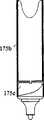
图23显示一具有中空把手136及刷头137的牙刷。在该把手136内的是一包含液体牙齿清洁剂、漱口药水或香水的筒135,其附接至先前所述型式的可手动操作的喷射泵结构139。该泵的出口是通过一导管138连接至该刷头137的基部,以便运送所需的液体至刷头。一止回阀140结合入该喷射泵的主体,以当操作该刷子时防止液体的泄漏。对施加在牙齿上的牙刷端部,该常规刷头137的变化是显示在图23a中。一与该把手136的轴线呈一直线的直刷头是显示在图23a的第一变型中,而一直角喷嘴及刷头是分别显示在该第二及第三变型137b及137c中。该端部是可替换的。FIG. 23 shows a toothbrush with a
实例8Example 8
参考图24至27,图24的可替换式墨水筒更换部件141是显示具有一用于附接的螺纹145、次级储存器144、及一防止墨水在使用前泄漏的隔膜143。Referring to Figures 24 to 27, the replaceable ink
根据图26,当在该可替换式墨水筒更换部件141的内侧和以可手动操作的喷射泵封闭时,导致该泵147的锐利尖端150刺穿该隔膜143及允许释放墨水。根据图25,当该筒处在该正常位置时,该标记流体能经过小孔149进入该内部的次级储存器144及在其内盛装少量的墨水。如图25a所示,当倒置该筒更换部件时,该次级储存器将保留该少量的标记流体,且其它的标记流体通过重力落至该筒141的另一端部,在此保留该其它的标记流体。然后可配送该少量的墨水。According to FIG. 26 , when closed inside the replaceable ink
如图27所示,当该可替换式筒位于该记号笔内侧时,通过在该方向X上的压按,该泵结构的一随后操作即配送该小的次级储存器144中的已准备好的预定流体量。持续的重复压力将不会导致配送任何更多的流体。As shown in FIG. 27, a subsequent operation of the pump mechanism dispenses the prepared liquid in the small
实例9Example 9
本实例如同实例24,但如图25c所示,该可替换式筒包括一小块毛毡或海绵144c以代替该次级储存器。当该筒处在图26的正常位置时,该海绵通过吸收一些流体墨水而用作次级储存器。当该筒旋转180度时,该海绵将保有一些标记流体及其它的标记流体将通过重力落至该筒的另一端部,如图25c所示。然后该泵结构的一随后操作可配送已在该海绵中的预定的少量流体。This example is like Example 24, but as shown in Figure 25c, the replaceable cartridge includes a small piece of felt or sponge 144c in place of the secondary reservoir. When the cartridge is in the normal position of Figure 26, the sponge acts as a secondary reservoir by absorbing some of the fluid ink. When the barrel is rotated 180 degrees, the sponge will hold some marking fluid and other marking fluid will fall by gravity to the other end of the barrel, as shown in Figure 25c. A subsequent operation of the pump structure can then dispense the predetermined small amount of fluid already in the sponge.
实例10Example 10
参考图28至32,该记号笔包括一作动器155、毛细管161、尾部柱塞156、毛毡160、尖端166b及主体165。Referring to FIGS. 28 to 32 , the marker pen includes an actuator 155 , capillary 161 , tail plunger 156 , felt 160 , tip 166 b and body 165 .
在从该记号笔移去该尾部柱塞156之后,该使用者将该喷嘴(该喷射泵的上柄)158插入该作动器155,该作动器是该笔165的一部分。为再次充填,该笔165的使用者的拇指或手指压按该配送容器151的基部,这可相对该喷嘴158以该泵主体157有效地纵向移动该配送容器。此在方向X的移动由该泵157内排除空气,以致当松开该容器151时,来自该次级储存器154内的墨水是经过该毛细管152向上吸入该泵157。然后该容器151基部的随后压按可从该泵157有效地配送墨水,以造成该墨水作为一射流153由该泵喷嘴158经过该作动器的一部分的毛细管161喷入该毛毡160。该毛细管161的长度大约是该毛毡长度的三分之一或更长,以便可轻易及迅速地经过该毛毡分布该流体墨水。亦应了解,可能需要数次压按该容器151的基部,以便完全排空该储存器154及装满该毛毡160。然后封闭该尾部柱塞156。After removing the tail plunger 156 from the marker, the user inserts the nozzle (upper handle of the jet pump) 158 into the actuator 155 , which is part of the pen 165 . To refill, the thumb or finger of the user of the pen 165 presses against the base of the dispensing container 151 , which effectively moves the dispensing container longitudinally with the pump body 157 relative to the nozzle 158 . This movement in direction X removes air from within the pump 157, so that when the container 151 is released, ink from the secondary reservoir 154 is drawn up through the capillary 152 into the pump 157. Subsequent pressing of the base of the container 151 can then effectively dispense ink from the pump 157 to cause the ink to be sprayed into the felt 160 as a jet 153 from the pump nozzle 158 through the capillary 161 that is part of the actuator. The length of the capillary 161 is about one third of the length of the felt or longer so that the fluid ink can be easily and quickly distributed through the felt. It should also be appreciated that it may be necessary to depress the base of the container 151 several times in order to completely empty the reservoir 154 and fill the felt 160 . The tail plunger 156 is then closed.
实例11Example 11
根据图33和36所示,塑料瓶170带有螺纹瓶颈180,用于关闭盖子166c,并包括带有供给管162和喷嘴168的次级储存器164以用于盛装标记流体。根据图34所示,在正常位置充满流体墨水的瓶170,带有供给管162和喷嘴168的次级储存器164都一起紧紧的固定到瓶170上。在这个位置,墨水将通过孔169进入储存器164。As shown in Figures 33 and 36, a plastic bottle 170 has a threaded neck 180 for closing the cap 166c and includes a secondary reservoir 164 with a supply tube 162 and nozzle 168 for containing marking fluid. According to FIG. 34, the bottle 170 filled with fluid ink in the normal position, the secondary reservoir 164 with the supply tube 162 and the nozzle 168 are all tightly secured to the bottle 170 together. In this position ink will enter reservoir 164 through aperture 169 .
根据图34a所示,当容器170被倒置,储存器164装有一定量墨水时,我们需要将笔再充满,其他液体将由于重力运动到另外一个方向。随后根据图36所示,塑料瓶170被沿箭头X方向挤压以通过供给管162配送仅在次级储存器164中的墨水作为滴175,滴入笔167的毛毡169内。According to Fig. 34a, when the container 170 is turned upside down and the reservoir 164 is filled with a certain amount of ink, we need to refill the pen, and the other liquid will move to another direction due to gravity. Subsequently according to FIG. 36 , the plastic bottle 170 is squeezed in the direction of arrow X to dispense the ink only in the secondary reservoir 164 through the supply tube 162 as
实例12Example 12
参考图37至42,其显示四种常规喷射泵结构的变型。在图37的第一及第二变型中显示两个止回阀171的实例。在每一实例中,该泵是在其壁面中具有一小的纵向止回阀171,以致当施加手动压力时空气能由该泵的主体173排出,及该液体是经过管子172由该泵主体173喷出。Referring to Figures 37 to 42, there are shown four variations of conventional jet pump configurations. An example of two
然而当倒置例如图41所示的常规泵时,液体可漏出该通气孔176。在图38所示的第三变型中,一小球阀174是设置在一引导远离该对流通气孔171的直角管177中,以当倒置该筒时封闭该通道及防止液体泄漏。当开始吸入时,该球174退后及该通道打开以便吸入液体及释放空气至该筒内侧。However, when a conventional pump such as that shown in FIG. 41 is inverted, liquid can leak out of the
图39显示的图38的泵结构是在该筒175的顶部紧紧地固定在适当位置。当倒置时,图39的筒以其尖端装入该记号笔的保持器175b,其方式如图26及27。当操作该泵时,该泵173的喷嘴172将该笔的标记流体喷入该毛毡175c。FIG. 39 shows the pump structure of FIG. 38 tightly held in place at the top of the
图40b显示整支笔,其中该笔盖是可转动的及用作该筒175的一按钮,以操作该泵。图41及42显示该EP-A-0126175的喷射泵,但在图42中已修改该喷射泵供用在本发明中。Figure 40b shows the complete pen where the cap is rotatable and acts as a button for the
如图42所示,已修改该通气孔176来包含图38所示的球阀178型式。在两种情况中,当施加手动压力时,在方向179上经过孔176推出空气。当倒置该喷射泵时,该球阀阻止墨水漏出该喷射泵。As shown in FIG. 42 , the
应了解所述每一具体实施例的筒基本上是相同的。可以理解,为明确或方便的缘故,亦可能在单一具体实施例中以任何组合提供在分开具体实施例的上下文中所述的本发明各种特征。反言之,为简明或其他缘故,亦可分开地或以任何合适的组合提供在单一具体实施例的上下文中所述的本发明各种特征。It should be understood that the cartridges of each of the embodiments described are substantially the same. It is to be understood that various features of the invention which are described in the context of separate embodiments may also be provided in any combination in a single embodiment, for reasons of clarity or convenience. Conversely, various features of the invention that are described in the context of a single particular embodiment, for brevity or otherwise, may also be provided separately or in any suitable combination.
Claims (34)
Translated fromChineseApplications Claiming Priority (6)
| Application Number | Priority Date | Filing Date | Title |
|---|---|---|---|
| GB0011689.7 | 2000-05-15 | ||
| GB0011689AGB2362354A (en) | 2000-05-15 | 2000-05-15 | Pump operated marker pen or brush |
| GB0023063.1 | 2000-09-20 | ||
| GB0023063AGB2367036B (en) | 2000-09-20 | 2000-09-20 | A marking instrument |
| GB0030949.2 | 2000-12-19 | ||
| GB0030949AGB2363096B (en) | 2000-05-15 | 2000-12-19 | Liquid-dispensing container for a marking instrument |
Related Child Applications (1)
| Application Number | Title | Priority Date | Filing Date |
|---|---|---|---|
| CNB2004100686544ADivisionCN1313283C (en) | 2000-05-15 | 2001-05-09 | Cartridge for a marking instrument which can be inverted to provide a metered supply of fluid |
Publications (2)
| Publication Number | Publication Date |
|---|---|
| CN1429152Atrue CN1429152A (en) | 2003-07-09 |
| CN1222426C CN1222426C (en) | 2005-10-12 |
Family
ID=27255718
Family Applications (2)
| Application Number | Title | Priority Date | Filing Date |
|---|---|---|---|
| CNB018095410AExpired - Fee RelatedCN1222426C (en) | 2000-05-15 | 2001-05-09 | Fluid Applicator |
| CNB2004100686544AExpired - Fee RelatedCN1313283C (en) | 2000-05-15 | 2001-05-09 | Cartridge for a marking instrument which can be inverted to provide a metered supply of fluid |
Family Applications After (1)
| Application Number | Title | Priority Date | Filing Date |
|---|---|---|---|
| CNB2004100686544AExpired - Fee RelatedCN1313283C (en) | 2000-05-15 | 2001-05-09 | Cartridge for a marking instrument which can be inverted to provide a metered supply of fluid |
Country Status (9)
| Country | Link |
|---|---|
| US (2) | US6986620B2 (en) |
| EP (2) | EP1289775B1 (en) |
| CN (2) | CN1222426C (en) |
| AT (1) | ATE315483T1 (en) |
| AU (1) | AU2001254954A1 (en) |
| DE (1) | DE60116617T2 (en) |
| DK (1) | DK1289775T3 (en) |
| ES (1) | ES2258082T3 (en) |
| WO (1) | WO2001087641A2 (en) |
Cited By (6)
| Publication number | Priority date | Publication date | Assignee | Title |
|---|---|---|---|---|
| CN101945595B (en)* | 2007-12-19 | 2012-11-21 | 克里斯托弗.赫特曼尼奥克 | Perfume bottle |
| CN102971157A (en)* | 2010-03-31 | 2013-03-13 | 汇美环球有限公司 | Refill system and method |
| CN103906449A (en)* | 2011-10-12 | 2014-07-02 | 株式会社衍宇 | Pump-type ampoule container capable of being refilled |
| CN106420332A (en)* | 2016-11-30 | 2017-02-22 | 邹彤昕 | A massage system integrating quantitative application of massage liquid and multiple massage methods |
| CN107074005A (en)* | 2014-10-16 | 2017-08-18 | 株式会社吴竹 | Ink packing tool |
| CN108081806A (en)* | 2017-02-28 | 2018-05-29 | 朱郎平 | A kind of application method for the liquid pens that supine position can be continuing with |
Families Citing this family (39)
| Publication number | Priority date | Publication date | Assignee | Title |
|---|---|---|---|---|
| CN1222426C (en)* | 2000-05-15 | 2005-10-12 | 阿什拉夫·马赫福兹·阿巴斯 | Fluid Applicator |
| USD529817S1 (en) | 2003-12-24 | 2006-10-10 | Expac Corporation | Fluid dispenser |
| US7467908B2 (en)* | 2003-12-24 | 2008-12-23 | Lucas Publications, Inc. | Fluid dispenser assembly |
| EP1547694B1 (en) | 2003-12-24 | 2012-02-08 | Lucas Packaging Group, Inc. | Fluid dispenser assembly |
| US20050239019A1 (en)* | 2004-04-21 | 2005-10-27 | Hall Teena V | Method of applying an antiseptic to an oral appliance |
| DE102005020426B4 (en)* | 2005-04-29 | 2017-05-04 | Leica Biosystems Nussloch Gmbh | Coverslipper |
| US20070039109A1 (en)* | 2005-08-11 | 2007-02-22 | Puneet Nanda | Toothbrush |
| US8517728B2 (en)* | 2007-01-24 | 2013-08-27 | Colgate-Palmolive Company | Oral care implement having fluid delivery system |
| US8276538B2 (en) | 2007-03-14 | 2012-10-02 | Depingo, Llc | Painting apparatuses and methods |
| US8408157B2 (en)* | 2007-03-14 | 2013-04-02 | Depingo, Llc | Painting apparatuses and methods |
| US9833296B2 (en) | 2007-04-27 | 2017-12-05 | Viscot Medical, Llc | Surgical marker |
| US20090142128A1 (en)* | 2007-11-29 | 2009-06-04 | Kurtis Johnson | Dry erase marker renewal device |
| WO2009105067A1 (en)* | 2008-02-19 | 2009-08-27 | Sossy Baghdoian | Artist's painting brush and method for using same |
| USD636668S1 (en) | 2008-03-24 | 2011-04-26 | Mary Kay Inc. | Dip tubes |
| US8376192B2 (en)* | 2008-03-24 | 2013-02-19 | Mary Kay Inc. | Apparatus for dispensing fluids using a press-fit diptube |
| USD588925S1 (en) | 2008-04-02 | 2009-03-24 | Mary Kay Inc. | Container |
| USD588916S1 (en) | 2008-04-02 | 2009-03-24 | Mary Kay Inc. | Container |
| US9789502B2 (en) | 2008-06-05 | 2017-10-17 | Mary Kay Inc. | Apparatus for dispensing fluids using a removable bottle |
| KR200452913Y1 (en) | 2008-08-14 | 2011-03-31 | 이소정 | Multifunctional brush |
| US8177452B2 (en)* | 2009-04-08 | 2012-05-15 | Yi Li Tsai | Nail polish container |
| US8092108B2 (en)* | 2009-12-30 | 2012-01-10 | Harry Bainbridge | Porous tip liquid applicator having draw fill mechanism |
| EP3300627B1 (en) | 2010-02-26 | 2020-09-30 | Colgate-Palmolive Company | Fluid delivery system for an oral care implement |
| US8398326B2 (en) | 2010-03-04 | 2013-03-19 | Colgate-Palmolive Company | Fluid dispensing oral care implement |
| US8668401B2 (en) | 2010-04-05 | 2014-03-11 | Frank Francavilla | Mascara dispensing device |
| WO2012121720A1 (en) | 2011-03-09 | 2012-09-13 | Colgate-Palmolive Company | Interdental cleaning device |
| EP2688684A2 (en)* | 2011-03-21 | 2014-01-29 | Breathable Foods, Inc. | Dispensing apparatus |
| CN102259714B (en) | 2011-07-26 | 2012-08-22 | 东莞怡信磁碟有限公司 | Portable emulsifiable paste charging bottle |
| WO2014066021A2 (en) | 2012-10-26 | 2014-05-01 | Colgate-Palmolive Company | Oral care implement |
| FR3008901B1 (en)* | 2013-07-26 | 2017-07-07 | Techniplast | LIQUID DISPENSING SYSTEM SUCH AS PERFUME AND RESERVOIR |
| US9686976B2 (en) | 2015-03-02 | 2017-06-27 | Bayer Cropscience Lp | Variable metered airless applicator with cartridge |
| MX2018015628A (en) | 2016-07-21 | 2019-04-11 | Philip Morris Products Sa | Dry powder inhaler. |
| JP6699440B2 (en)* | 2016-08-12 | 2020-05-27 | シヤチハタ株式会社 | Ink replenishing device |
| JP6699441B2 (en)* | 2016-08-12 | 2020-05-27 | シヤチハタ株式会社 | Ink replenishing device |
| WO2018191300A1 (en) | 2017-04-10 | 2018-10-18 | Sage Products, Llc | Twist seal oral fluid delivery device |
| US10730338B2 (en)* | 2017-04-26 | 2020-08-04 | Hayden R Murphy | Fluid applicator refill system |
| US10532376B2 (en) | 2017-07-19 | 2020-01-14 | Derik (JiangSu) Industrial Co., LTD | Dispenser for storing and advancing a liquid |
| WO2019133317A1 (en)* | 2017-12-29 | 2019-07-04 | Colgate-Palmolive Company | Dispenser system |
| EP3922477A1 (en)* | 2020-06-12 | 2021-12-15 | Société BIC | Pen with multiple colors |
| EP4112328A1 (en) | 2021-06-30 | 2023-01-04 | BIC Violex Single Member S.A. | Variable color shade marker |
Family Cites Families (25)
| Publication number | Priority date | Publication date | Assignee | Title |
|---|---|---|---|---|
| US3089465A (en)* | 1960-03-04 | 1963-05-14 | Hunt Mfg Co | Lettering instrument |
| US3420610A (en)* | 1966-08-08 | 1969-01-07 | Paper Mate Mfg Co | Writing instruments and self-pressurizing assemblies therefor |
| FR2149669A5 (en) | 1971-08-19 | 1973-03-30 | Step | |
| US3792932A (en)* | 1972-05-16 | 1974-02-19 | E Henriksen | Ink feed for ball point pens |
| US4029261A (en) | 1976-04-30 | 1977-06-14 | Jaime Olegnowicz | Piston displacement liquid spray pumps |
| IT7722113U1 (en) | 1977-09-06 | 1979-03-06 | Ruscitti Tomaso | HAND PUMP FOR DISPENSING MICRONIZED LIQUIDS AT PRESET PRESSURE |
| US4472462A (en)* | 1981-04-21 | 1984-09-18 | Mark-Tex Corporation | Paint applying method using marking device |
| DK315483A (en)* | 1982-07-17 | 1984-01-18 | Lingner & Fischer Gmbh | DISPENSES FOR LIQUID ADHESIVES |
| DE3374278D1 (en) | 1983-05-20 | 1987-12-10 | Yoshino Kogyosho Co Ltd | Manually-operated sprayer |
| IT1204879B (en)* | 1985-05-29 | 1989-03-10 | Mitsubishi Pencil Co | WRITING OR PAINTING TOOL |
| JPH0615278B2 (en)* | 1986-04-03 | 1994-03-02 | 三菱鉛筆株式会社 | Liquid applicator such as writing implements or cosmetics |
| JPS6382481U (en)* | 1986-11-17 | 1988-05-30 | ||
| US4966483A (en)* | 1987-11-12 | 1990-10-30 | Ancos Co., Ltd. | Valve operating mechanism |
| JPH0295576U (en)* | 1989-01-09 | 1990-07-30 | ||
| JPH084883Y2 (en)* | 1990-02-10 | 1996-02-14 | 三菱鉛筆株式会社 | Liquid applicator |
| ES1016723Y (en) | 1991-01-29 | 1992-08-01 | Sanchez Sotos Jose Manuel | IMPROVED PEN-SPRAYER. |
| DE4411355A1 (en)* | 1994-03-31 | 1995-11-30 | Ahrens Hans Joachim Dipl Phys | Refill bottle for marker, printer cartridge and cassette |
| JP3210181B2 (en)* | 1994-06-22 | 2001-09-17 | 三菱鉛筆株式会社 | Writing implement |
| CN2222074Y (en)* | 1994-12-01 | 1996-03-13 | 刘宏生 | Compression type ink bottle and tail-absorbing type pen |
| CN2244347Y (en)* | 1995-12-13 | 1997-01-08 | 贺思检 | Washing brush |
| AU718986B2 (en) | 1997-08-13 | 2000-05-04 | Yoshino Kogyosho Co., Ltd. | Manually operated spray device for liquid |
| CN2365069Y (en)* | 1999-04-01 | 2000-02-23 | 陈文广 | Pressing ink type pen and its ink-pressing-in device |
| US6224284B1 (en)* | 1999-10-12 | 2001-05-01 | Dri Mark Products Incorporated | Metallic ink composition for wick type writing instruments |
| CN1222426C (en)* | 2000-05-15 | 2005-10-12 | 阿什拉夫·马赫福兹·阿巴斯 | Fluid Applicator |
| US6592282B2 (en)* | 2000-12-11 | 2003-07-15 | Revlon Consumer Products Corporation | Cosmetic applicator for fluid material |
- 2001
- 2001-05-09CNCNB018095410Apatent/CN1222426C/ennot_activeExpired - Fee Related
- 2001-05-09DKDK01928088Tpatent/DK1289775T3/enactive
- 2001-05-09ATAT01928088Tpatent/ATE315483T1/ennot_activeIP Right Cessation
- 2001-05-09EPEP01928088Apatent/EP1289775B1/ennot_activeExpired - Lifetime
- 2001-05-09EPEP04078045Apatent/EP1557289A1/ennot_activeWithdrawn
- 2001-05-09DEDE60116617Tpatent/DE60116617T2/ennot_activeExpired - Fee Related
- 2001-05-09CNCNB2004100686544Apatent/CN1313283C/ennot_activeExpired - Fee Related
- 2001-05-09AUAU2001254954Apatent/AU2001254954A1/ennot_activeAbandoned
- 2001-05-09USUS10/276,216patent/US6986620B2/ennot_activeExpired - Fee Related
- 2001-05-09WOPCT/GB2001/002031patent/WO2001087641A2/enactiveIP Right Grant
- 2001-05-09ESES01928088Tpatent/ES2258082T3/ennot_activeExpired - Lifetime
- 2005
- 2005-12-30USUS11/323,797patent/US20070020032A1/ennot_activeAbandoned
Cited By (9)
| Publication number | Priority date | Publication date | Assignee | Title |
|---|---|---|---|---|
| CN101945595B (en)* | 2007-12-19 | 2012-11-21 | 克里斯托弗.赫特曼尼奥克 | Perfume bottle |
| CN102971157A (en)* | 2010-03-31 | 2013-03-13 | 汇美环球有限公司 | Refill system and method |
| CN102971157B (en)* | 2010-03-31 | 2015-11-25 | 汇美环球有限公司 | Refill system and method |
| CN103906449A (en)* | 2011-10-12 | 2014-07-02 | 株式会社衍宇 | Pump-type ampoule container capable of being refilled |
| CN107074005A (en)* | 2014-10-16 | 2017-08-18 | 株式会社吴竹 | Ink packing tool |
| US10081216B2 (en) | 2014-10-16 | 2018-09-25 | Kuretake Co., Ltd. | Ink filling tool |
| CN106420332A (en)* | 2016-11-30 | 2017-02-22 | 邹彤昕 | A massage system integrating quantitative application of massage liquid and multiple massage methods |
| CN106420332B (en)* | 2016-11-30 | 2019-01-11 | 安徽誉望之子科技有限公司 | A massage system integrating quantitative application of massage liquid and various massage methods |
| CN108081806A (en)* | 2017-02-28 | 2018-05-29 | 朱郎平 | A kind of application method for the liquid pens that supine position can be continuing with |
Also Published As
| Publication number | Publication date |
|---|---|
| US20070020032A1 (en) | 2007-01-25 |
| DK1289775T3 (en) | 2006-05-22 |
| DE60116617D1 (en) | 2006-04-06 |
| DE60116617T2 (en) | 2006-09-14 |
| EP1289775B1 (en) | 2006-01-11 |
| WO2001087641B1 (en) | 2002-03-14 |
| ES2258082T3 (en) | 2006-08-16 |
| US6986620B2 (en) | 2006-01-17 |
| WO2001087641A3 (en) | 2002-01-31 |
| EP1289775A2 (en) | 2003-03-12 |
| AU2001254954A1 (en) | 2001-11-26 |
| ATE315483T1 (en) | 2006-02-15 |
| WO2001087641A2 (en) | 2001-11-22 |
| CN1600563A (en) | 2005-03-30 |
| US20030123921A1 (en) | 2003-07-03 |
| CN1313283C (en) | 2007-05-02 |
| EP1557289A1 (en) | 2005-07-27 |
| CN1222426C (en) | 2005-10-12 |
Similar Documents
| Publication | Publication Date | Title |
|---|---|---|
| CN1429152A (en) | Fluid Applicator | |
| CN102971157B (en) | Refill system and method | |
| US8087843B2 (en) | Liquid dentifrice dispensing toothbrush | |
| EP0599834B1 (en) | Toothbrush and paste dispenser | |
| US3256894A (en) | Dispensing-type toothbrush | |
| US4244525A (en) | Writing instrument with refillable scent dispenser | |
| US7244073B2 (en) | Travel toothbrush assembly | |
| US8177452B2 (en) | Nail polish container | |
| US20070041779A1 (en) | Manual and electrical pump toothbrushes for dispensing liquid and paste dentifrices | |
| CN103079969A (en) | Knocking-type discharge container | |
| CN1642698A (en) | Hair removal device with lotion applicator | |
| CA2867154A1 (en) | Precision liquid applicator | |
| US9930957B2 (en) | Dental devices with liquid applicator | |
| US6719471B1 (en) | Toothbrush incorporating a toothpaste reservoir | |
| US20020082545A1 (en) | Mouth cavity irrigation unit | |
| HK1076071A (en) | Cartridge for a marking instrument invertable to provide closed fluid supply | |
| TWI262857B (en) | A fluid applicator instrument | |
| GB2330523A (en) | Reservoir toothbrush | |
| JPH07144168A (en) | Applicator | |
| US20200253458A1 (en) | Stemware cleaning device | |
| JP2024092575A (en) | Transfer-filling member and transfer-filling system | |
| GB2363096A (en) | Replaceable cartridge for a marking implement invertable to provide dosed fluid supply | |
| JP2023154285A (en) | Liquid injection device and closed container into which liquid is injected using the same | |
| JP2005230595A (en) | Sprayer | |
| KR20180040860A (en) | Toothbrush with toothpaste therein |
Legal Events
| Date | Code | Title | Description |
|---|---|---|---|
| C06 | Publication | ||
| PB01 | Publication | ||
| C10 | Entry into substantive examination | ||
| SE01 | Entry into force of request for substantive examination | ||
| C14 | Grant of patent or utility model | ||
| GR01 | Patent grant | ||
| C17 | Cessation of patent right | ||
| CF01 | Termination of patent right due to non-payment of annual fee | Granted publication date:20051012 Termination date:20110509 |