CN1428710A - Multifunctional electronic peripheral card - Google Patents
Multifunctional electronic peripheral cardDownload PDFInfo
- Publication number
- CN1428710A CN1428710ACN01144890ACN01144890ACN1428710ACN 1428710 ACN1428710 ACN 1428710ACN 01144890 ACN01144890 ACN 01144890ACN 01144890 ACN01144890 ACN 01144890ACN 1428710 ACN1428710 ACN 1428710A
- Authority
- CN
- China
- Prior art keywords
- interrupt
- functional device
- host
- queue
- status register
- Prior art date
- Legal status (The legal status is an assumption and is not a legal conclusion. Google has not performed a legal analysis and makes no representation as to the accuracy of the status listed.)
- Pending
Links
Images

Classifications
- G—PHYSICS
- G06—COMPUTING OR CALCULATING; COUNTING
- G06K—GRAPHICAL DATA READING; PRESENTATION OF DATA; RECORD CARRIERS; HANDLING RECORD CARRIERS
- G06K19/00—Record carriers for use with machines and with at least a part designed to carry digital markings
- G06K19/06—Record carriers for use with machines and with at least a part designed to carry digital markings characterised by the kind of the digital marking, e.g. shape, nature, code
- G06K19/067—Record carriers with conductive marks, printed circuits or semiconductor circuit elements, e.g. credit or identity cards also with resonating or responding marks without active components
- G06K19/07—Record carriers with conductive marks, printed circuits or semiconductor circuit elements, e.g. credit or identity cards also with resonating or responding marks without active components with integrated circuit chips
- G06K19/0719—Record carriers with conductive marks, printed circuits or semiconductor circuit elements, e.g. credit or identity cards also with resonating or responding marks without active components with integrated circuit chips at least one of the integrated circuit chips comprising an arrangement for application selection, e.g. an acceleration sensor or a set of radio buttons
- G—PHYSICS
- G06—COMPUTING OR CALCULATING; COUNTING
- G06K—GRAPHICAL DATA READING; PRESENTATION OF DATA; RECORD CARRIERS; HANDLING RECORD CARRIERS
- G06K19/00—Record carriers for use with machines and with at least a part designed to carry digital markings
- G06K19/06—Record carriers for use with machines and with at least a part designed to carry digital markings characterised by the kind of the digital marking, e.g. shape, nature, code
- G06K19/067—Record carriers with conductive marks, printed circuits or semiconductor circuit elements, e.g. credit or identity cards also with resonating or responding marks without active components
- G06K19/07—Record carriers with conductive marks, printed circuits or semiconductor circuit elements, e.g. credit or identity cards also with resonating or responding marks without active components with integrated circuit chips
Landscapes
- Engineering & Computer Science (AREA)
- Computer Hardware Design (AREA)
- Microelectronics & Electronic Packaging (AREA)
- Physics & Mathematics (AREA)
- General Physics & Mathematics (AREA)
- Theoretical Computer Science (AREA)
- Bus Control (AREA)
- Computer And Data Communications (AREA)
Abstract
Description
Translated fromChinese技术领域technical field
本发明是有关一种电子周边卡,尤指一种多功能电子周边卡。The invention relates to an electronic peripheral card, especially a multifunctional electronic peripheral card.
背景技术Background technique
在现今的电脑系统架构中,有许多使用单一介面而提供两种或两种以上功能的电子周边卡,以现有的PCMCIA/CF介面而言,便有区域网路/数据机卡(LAN+Modem PC Card)、整合服务数字网路/数据机卡(ISDN+Modem PC card)、双序列接口卡(Dual serial port PC card)等等,图1便显示可支援n个功能装置的PCMCIA/CF卡,由其多功能控制器11,使得n个功能装置12可与主机系统连接,而依据PCMCIA/CF的规格,在该多功能控制器11需内建有n组功能组态暂存器(FCR),因此,该多功能控制器11亦包含有n组组态状态暂存器(CSR),而每一CSR即对应一功能装置12,其提供主机系统有关所对应的功能装置的控制及状态资料,例如,CSR的比特I(D1)是为一中断状态比特,亦即,当有一功能装置12提出中断要求(IRQ)时,则所对应的CSR的比特1将被设定为1。In today's computer system architecture, there are many electronic peripheral cards that use a single interface and provide two or more functions. For the existing PCMCIA/CF interface, there are local area network/modem cards (LAN+ Modem PC Card), integrated services digital network/data machine card (ISDN+Modem PC card), dual serial interface card (Dual serial port PC card), etc. Figure 1 shows the PCMCIA/CF that can support n functional devices Card, by its multi-function controller 11, makes n functional devices 12 can be connected with host computer system, and according to the specification of PCMCIA/CF, in this multi-function controller 11 need built-in n groups of function configuration registers ( FCR), therefore, the multi-function controller 11 also includes n groups of configuration status registers (CSR), and each CSR corresponds to a functional device 12, which provides the control and control of the corresponding functional device of the host system. Status data, for example, bit 1 (D1) of the CSR is an interrupt status bit, that is, when a functional device 12 issues an interrupt request (IRQ), the
如该n个功能装置中有p个装置发出中断要求给该多功能控制器11,在传统的作法上,如图2所示,首先,功能装置A发出第1个中断要求IRO,故功能装置A的CSR的D1被设为1,同时其他功能装置亦发出中断要求IRO,而对应的CSR的D1亦被设为1,于是将多功能控制器11对应主机的总线的Host IREO#信号线拉下,透过主机的总线而通知主机有中断要求,而中断服务常式(ISR)便开始检查该多功能控制器11,得知所有内建的CSR有P组的D1被设为1,因此CSR将记录此P组IRO资料于一中断项目表(Interrupt entry table)中,然后清除所有CSR的D1为0,并开始依照记录于中断项目表的内容,先服务功能装置A并设定功能装置A的CSR的D1为1,当服务完毕之后,发出中断结束(EOI)命令并清除功能装置A的CSR的D1为0,此时,此P组所有CSR的D1亦为0,于是ISR再次依据中断项目表的记录,决定服务第2个功能装置B,故设定功能装置B的CSR的D1为1,直到服务完毕后,执行EOI命令以清除功能装置B的CSR的D1为0,依此方式执行服务常式,直至服务完第p个功能装置,其IRO的时序图如图3所示。If there are p devices among the n functional devices to send an interrupt request to the multi-function controller 11, in the traditional way, as shown in Figure 2, at first, the functional device A sends the first interrupt request IRO, so the functional device D1 of the CSR of A is set to 1, and other functional devices also send an interrupt request IRO at the same time, and D1 of the corresponding CSR is also set to 1, so the host IREO# signal line of the multi-function controller 11 corresponding to the bus of the host is pulled Next, the host computer is notified that there is an interrupt request through the bus of the host computer, and the interrupt service routine (ISR) starts to check the multi-function controller 11, knowing that all built-in CSRs have D1 of the P group set to 1, so The CSR will record the P-group IRO data in an Interrupt entry table, then clear the D1 of all CSRs to 0, and start to serve the functional device A and set the functional device according to the content recorded in the interrupt entry table D1 of A’s CSR is 1. After the service is completed, issue an end-of-interrupt (EOI) command and clear the function. Interrupt the record of the item table and decide to serve the second functional device B, so set D1 of the CSR of functional device B to 1 until the service is completed, execute the EOI command to clear D1 of the CSR of functional device B to 0, and so on Execute the service routine in this way until the pth functional device is serviced. The timing diagram of its IRO is shown in Figure 3.
由以上的示例可知,在已知的多功能电子周边卡中,当服务多个IRO时,由于主机端需不断地设定及清除多功能控制器11的CSR的D1,故而造成主机端极大的负担,进而导致处理功能装置时间的延迟,并且无法有效管理及支援功能装置,因此,前述已知的多功能电子周边卡实有予以改进的必要。From the above examples, it can be seen that in the known multi-function electronic peripheral card, when multiple IROs are served, the host needs to constantly set and clear D1 of the CSR of the multi-function controller 11, so the host end is extremely large. The burden of processing the functional device further leads to a delay in processing the functional device, and it is impossible to effectively manage and support the functional device. Therefore, it is necessary to improve the aforementioned known multifunctional electronic peripheral card.
创作人爰因于此,本于积极创新的精神,亟思一种可以解决上述问题的,几经研究实验终至完成此项新颖进步的创作。Because of this, the creators, in the spirit of active innovation, eagerly thought of a way to solve the above problems, and finally completed this novel and progressive creation after several researches and experiments.
发明内容Contents of the invention
本发明的目的是在提供一种多功能电子周边卡,以便解决已知技术的缺点,而具有主机端的负担小,处理功能装置的时间短,并可有效管理及支援功能装置。The object of the present invention is to provide a multifunctional electronic peripheral card to solve the disadvantages of the known technology, which has a small burden on the host side, a short time for processing functional devices, and can effectively manage and support functional devices.
为达前述的目的,本发明的多功能电子周边卡主要包括一用以与主机连接的主机界面、一多功能控制器、以及多个功能装置,每一个功能装置是由向该多功能控制器发出中断要求,而可透过主机界面与主机连接,该多功能控制器具有一中断队列(Interrupt Queue)及一中断状态暂存器,该中断状态暂存器的每一比特对应一功能装置,以当有一功能装置发出中断要求时,将代表该功能装置的编号存入中断队列,并在中断状态暂存器的所有比特D1均为0时,才将该中断状态暂存器的对应比特设为1,以便可向主机发出中断要求,且在主机服务完该功能装置后,更新该功能装置中断队列及清除该功能装置中断状态暂存器。For reaching the aforementioned purpose, the multifunctional electronic peripheral card of the present invention mainly includes a host interface for being connected with the host, a multifunctional controller, and a plurality of functional devices, each functional device is connected to the multifunctional controller. Send an interrupt request, and can be connected to the host through the host interface. The multi-function controller has an interrupt queue (Interrupt Queue) and an interrupt status register. Each bit of the interrupt status register corresponds to a functional device, so as to When a functional device sends an interrupt request, the number representing the functional device is stored in the interrupt queue, and when all bits D1 of the interrupt status register are 0, the corresponding bit of the interrupt status register is set to 1, so as to send an interrupt request to the host, and after the host finishes servicing the functional device, update the interrupt queue of the functional device and clear the interrupt status register of the functional device.
其中该中断状态暂存器具有复数比特,且当某一比特被设为1时,即表示该比特所对应的功能装置需要中断服务。The interrupt status register has a plurality of bits, and when a certain bit is set to 1, it means that the functional device corresponding to the bit needs interrupt service.
其中该中断队列具有复数个项目,以便供以先进先出的方式,存放需要中断服务的功能装置的编号,且该中断队列并以第一指标及第二指标分别指向队列的起始及结束项目。Wherein the interrupt queue has a plurality of items, so as to store the number of the functional device requiring interrupt service in a first-in-first-out manner, and the interrupt queue points to the start and end items of the queue with the first pointer and the second pointer respectively .
其中当主机收到中断要求后,是依据中断队列的第一指标所指的内容而服务对应的功能装置。Wherein, when the host receives the interrupt request, it serves the corresponding functional device according to the content indicated by the first index of the interrupt queue.
其中该主机界面是为PCMCIA/CF界面。Wherein the host interface is a PCMCIA/CF interface.
其中该中断状态暂存器是代表PCMCIA/CF规格所定义的CSR比特1的集合。The interrupt status register represents a set of
由于本发明构造新颖,能提供产业上利用,且确有增进功效,故依法申请专利。Because the present invention has a novel structure, can provide industrial application, and has indeed enhanced effects, it applies for a patent according to law.
附图说明Description of drawings
为使审查员能进一步了解本发明的结构、特征及其目的,以下结合附图及较佳具体实施例的详细说明如后,其中:In order to enable the examiner to further understand the structure, features and purpose of the present invention, the following detailed description in conjunction with the drawings and preferred specific embodiments is as follows, wherein:
图1是为一可支援n个功能装置的PCMCIA/CF卡的架构图;Fig. 1 is a structural diagram of a PCMCIA/CF card that can support n functional devices;
图2是显示在图1的n个功能装置中有p个装置发出中断要求的示意图;Fig. 2 is a schematic diagram showing that p devices among the n functional devices of Fig. 1 send interrupt requests;
图3是显示图1的架构的IRO时序图;FIG. 3 is an IRO timing diagram showing the architecture of FIG. 1;
图4是为本发明的多功能电子周边卡的架构图;Fig. 4 is the frame diagram of the multifunctional electronic peripheral card of the present invention;
图5是为本发明的多功能电子周边卡的操作流程图;Fig. 5 is the operation flowchart of the multifunctional electronic peripheral card of the present invention;
图6是显示本发明的多功能电子周边卡的一实际操作范例。FIG. 6 shows an example of actual operation of the multifunctional electronic peripheral card of the present invention.
具体实施方式Detailed ways
有关本发明的多功能电子周边卡的一较佳实施例,请先参照图4所示,其包括有多个功能装置42、多功能控制器41及主机界面43,其中,每一个功能装置42是由向该多功能控制器41发出中断要求(IRO),而可透过主机界面43与主机系统连接,该主机界面43是较佳地为PCMCIA/CF界面。Regarding a preferred embodiment of the multifunctional electronic peripheral card of the present invention, please first refer to shown in Figure 4, which includes a plurality of functional devices 42, a multifunctional controller 41 and a host interface 43, wherein each functional device 42 By sending an interrupt request (IRO) to the multi-function controller 41, it can be connected with the host system through the host interface 43, and the host interface 43 is preferably a PCMCIA/CF interface.
前述多功能控制器41具有一控制单元411、一中断队列412及一中断状态暂存器413,该中断状态暂存器413具有复数中断状态比特,每一中断状态比特对应一功能装置42,亦即,当某一中断状态比特被设为1时,即表示该比特所对应的功能装置42需要中断服务。于本较佳实施例中,是以该多功能电子周边卡具有编号0至7的8个功能装置42为例说明,而该中断状态暂存器413则具有8比特。该中断队列412具有复数个项目,共计8个中断状态比特,以便供以先进先出的方式,存放需要中断服务的功能装置42的编号,该中断队列412并以第一指标P1及第二指标P2分别指向队列的起始及结束项目。该中断状态暂存器413是代表PCMCIA/CF规格所定义的CSR比特1的集合。The aforementioned multifunctional controller 41 has a control unit 411, an interrupt queue 412, and an interrupt status register 413. The interrupt status register 413 has a plurality of interrupt status bits, and each interrupt status bit corresponds to a functional device 42, also That is, when a certain interrupt status bit is set to 1, it means that the functional device 42 corresponding to the bit needs interrupt service. In this preferred embodiment, the multifunctional electronic peripheral card has 8 functional devices 42 numbered 0 to 7 as an example, and the interrupt status register 413 has 8 bits. The interrupt queue 412 has a plurality of items, a total of 8 interrupt status bits, in order to store the number of the functional device 42 that needs interrupt service in a first-in-first-out manner. The interrupt queue 412 uses the first index P1 and the second index P2 points to the start and end items of the queue respectively. The interrupt status register 413 represents a set of
前述控制单元411是用以依据该等功能装置42所发出的IRO来分配中断服务的规则,参照图5的流程所示,当有一编号为x的功能装置42发出中断要求时,首先,于步骤S501中,将编号x存入中断队列412并更新指标P1及P2,步骤S502判断该中断状态暂存器413的所有比特是否均为0,如是,则表示的前均未有其他功能装置提出中断要求,因此,将该中断状态暂存器413的第x个比特设为1(步骤8503),如此,便可向主机发出中断要求(步骤S504)。另,如步骤S502判断该中断状态暂存器413已有比特被设为1,则表示的前已有其他功能装置提出中断要求,而不再设定该中断状态暂存器413的比特值。The aforementioned control unit 411 is used for distributing interrupt service rules according to the IROs issued by these functional devices 42. As shown in the flow chart of FIG. In S501, the number x is stored in the interrupt queue 412 and the indicators P1 and P2 are updated. Step S502 judges whether all the bits of the interrupt status register 413 are 0. If so, no other functional devices have proposed an interrupt before the representation. Therefore, the xth bit of the interrupt status register 413 is set to 1 (step 8503), so that an interrupt request can be sent to the host (step S504). In addition, if the step S502 judges that the interrupt state register 413 has a bit set to 1, it means that other functional devices have made an interrupt request before, and the bit value of the interrupt state register 413 is no longer set.
而当主机收到中断要求后,便依据中断队列412的指标P1所指的内容(编号x)而服务编号x的功能装置(步骤S505),之后,更新该中断队列412及清除中断状态暂存器413(步骤S506),并检查该中断队列412是否为空(步骤S507),如是,则表示已完成所有功能装置的中断服务,否则,需再依据指标P1所指的内容,而将中断状态暂存器413相应的比特设为1(步骤S503),如此重复执行直至中断队列412为空。And after main frame receives interrupt request, just according to the content (number x) indicated by the index P1 of interrupt queue 412 and the functional device of service number x (step S505), afterward, update this interrupt queue 412 and clear interrupt status temporary storage device 413 (step S506), and check whether the interrupt queue 412 is empty (step S507), if so, it means that the interrupt service of all functional devices has been completed, otherwise, the interrupt status needs to be changed according to the content indicated by the index P1 The corresponding bit of the temporary register 413 is set to 1 (step S503 ), and this is repeated until the interrupt queue 412 is empty.
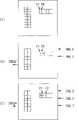
举例而言,当系统初始化之后,没有任何中断要求,中断队列412没有任何项目,中断状态暂存器413的比特值全为0,如图6(A)所示,指标P1及P2全指向中断队列412的第0位置。之后,当功能装置0发出中断要求IRO0,则此IRO0被存入中断队列412,并检查得知中断状态暂存器413的比特值均为0,于是将对应于功能装置0的比特0设为1。在此同时,功能装置2亦发出中断要求IRO2,则此IRO2被存入中断队列412的第1位置,同时指标P2指向该位置,如图6(B)所示。For example, after the system is initialized, there is no interrupt request, the interrupt queue 412 does not have any items, and the bit values of the interrupt status register 413 are all 0, as shown in FIG. 6(A), indicators P1 and P2 all point to interrupts
由于此时在中断状态暂存器413的比特0已被设为1,因此,不再设定比特2。另IRO0亦由主机总线发出IREO#信号通知主机,当主机收到IREO#后,中断服务常式便开始检查多功能控制器中,对应的CSR的中断比特D1已被设为1,而得知先服务IRO0的功能装置0,且检查指标P1及P2地址,亦得知另有功能装置2有一IRO2被伫存于中断队列412中,为下一个继续服务的对象。Since
若功能装置7亦也发出中断要求IRO7,则指标P2再往后移动,如图6(C)所示,此时,由于已服务完IRO0,对应的CSR的中断比特D1将自动回复为0,无须主机系统来清除。故中断状态暂存器413的比特2被设为1而对主机发出中断要求。而中断服务常式则检查对应的CSR的中断比特D1已被设为1,而开始服务IRO2的功能装置2,之后,亦以同的机制服务功能装置7。If the
由以上的说明可知,本发明是由中断队列拦住功能装置所发出的中断要求,并控制在仅当中断状态暂存器全为0时,才处理一功能装置的中断要求,以将该中断状态暂存器对应于该功能装置的比特设为1,以便对主机发出中断要求,如此,可使多个功能装置的中断要求依序被主机服务,而主机端无须不断地设定及清除中断状态暂存器,故不会造成主机端的负担。As can be seen from the above description, the present invention blocks the interrupt request sent by the functional device by the interrupt queue, and controls the interrupt request of a functional device only when the interrupt status register is all 0, so that the interrupt status The bit of the temporary register corresponding to the functional device is set to 1 in order to send an interrupt request to the host. In this way, the interrupt requests of multiple functional devices can be served by the host in sequence, and the host does not need to constantly set and clear the interrupt status. scratchpad, so it will not cause a burden on the host side.
综上所述,本发明无论就目的、手段及功效,在在均显示其迥异于已知技术的特征,实为一极具实用价值的创作。惟应注意的是,上述诸多实施例仅是为了便于说明而举例而已,本发明所主张的权利范围自应以申请权利要求范围所述为准,而非仅限于上述实施例。To sum up, no matter the purpose, means and effect of the present invention, it shows its characteristics that are very different from the known technology, and it is a creation with great practical value. However, it should be noted that the above-mentioned embodiments are examples only for the convenience of description, and the scope of rights claimed by the present invention should be determined by the scope of claims in the application, rather than limited to the above-mentioned embodiments.
Claims (6)
Translated fromChinesePriority Applications (3)
| Application Number | Priority Date | Filing Date | Title |
|---|---|---|---|
| CN01144890ACN1428710A (en) | 2001-12-28 | 2001-12-28 | Multifunctional electronic peripheral card |
| JP2002012543AJP4014876B2 (en) | 2001-12-28 | 2002-01-22 | Multifunctional electronic peripheral card |
| US10/151,926US6764017B2 (en) | 2001-12-28 | 2002-05-22 | Multi-function electronic card |
Applications Claiming Priority (3)
| Application Number | Priority Date | Filing Date | Title |
|---|---|---|---|
| CN01144890ACN1428710A (en) | 2001-12-28 | 2001-12-28 | Multifunctional electronic peripheral card |
| JP2002012543AJP4014876B2 (en) | 2001-12-28 | 2002-01-22 | Multifunctional electronic peripheral card |
| US10/151,926US6764017B2 (en) | 2001-12-28 | 2002-05-22 | Multi-function electronic card |
Publications (1)
| Publication Number | Publication Date |
|---|---|
| CN1428710Atrue CN1428710A (en) | 2003-07-09 |
Family
ID=32045507
Family Applications (1)
| Application Number | Title | Priority Date | Filing Date |
|---|---|---|---|
| CN01144890APendingCN1428710A (en) | 2001-12-28 | 2001-12-28 | Multifunctional electronic peripheral card |
Country Status (3)
| Country | Link |
|---|---|
| US (1) | US6764017B2 (en) |
| JP (1) | JP4014876B2 (en) |
| CN (1) | CN1428710A (en) |
Cited By (2)
| Publication number | Priority date | Publication date | Assignee | Title |
|---|---|---|---|---|
| CN102193056A (en)* | 2010-01-25 | 2011-09-21 | 爱德万测试株式会社 | Test apparatus and test method |
| CN108304334A (en)* | 2017-01-13 | 2018-07-20 | 三星电子株式会社 | Application processor and integrated circuit including interrupt control unit |
Families Citing this family (12)
| Publication number | Priority date | Publication date | Assignee | Title |
|---|---|---|---|---|
| US7107378B1 (en) | 2000-09-01 | 2006-09-12 | Sandisk Corporation | Cooperative interconnection and operation of a non-volatile memory card and an input-output card |
| US7822672B2 (en)* | 2001-04-20 | 2010-10-26 | Bloomberg L.P. | Price change of orders from reserve in an electronic trading system |
| US7440774B2 (en)* | 2002-04-08 | 2008-10-21 | Socket Mobile, Inc. | Wireless enabled memory module |
| US7367503B2 (en) | 2002-11-13 | 2008-05-06 | Sandisk Corporation | Universal non-volatile memory card used with various different standard cards containing a memory controller |
| US8037229B2 (en)* | 2002-11-21 | 2011-10-11 | Sandisk Technologies Inc. | Combination non-volatile memory and input-output card with direct memory access |
| US20050055479A1 (en)* | 2002-11-21 | 2005-03-10 | Aviad Zer | Multi-module circuit card with inter-module direct memory access |
| US7305535B2 (en)* | 2003-04-17 | 2007-12-04 | Sandisk Corporation | Memory cards including a standard security function |
| WO2005048176A1 (en) | 2003-11-12 | 2005-05-26 | Matsushita Electric Industrial Co., Ltd. | Electronic device and control method thereof |
| US7209995B2 (en)* | 2003-12-09 | 2007-04-24 | Sandisk Corporation | Efficient connection between modules of removable electronic circuit cards |
| TWI506621B (en)* | 2005-12-22 | 2015-11-01 | Kao Corp | Polishing liquid composition for hard disk substrate |
| CN104111866A (en)* | 2013-04-18 | 2014-10-22 | 鸿富锦精密工业(深圳)有限公司 | Interrupt control system and interrupt control method |
| GB2521121A (en)* | 2013-11-07 | 2015-06-17 | St Microelectronics Res & Dev | A method and apparatus use with interrupts |
Family Cites Families (5)
| Publication number | Priority date | Publication date | Assignee | Title |
|---|---|---|---|---|
| US5794014A (en)* | 1994-06-27 | 1998-08-11 | Cirrus Logic, Inc. | Method and apparatus for interfacing between peripherals of multiple formats and a single system bus |
| US5805929A (en)* | 1996-01-29 | 1998-09-08 | International Business Machines Corporation | Multiple independent I/O functions on a PCMCIA card share a single interrupt request signal using an AND gate for triggering a delayed RESET signal |
| US6006301A (en)* | 1997-09-30 | 1999-12-21 | Intel Corporation | Multi-delivery scheme interrupt router |
| US6081867A (en)* | 1998-05-20 | 2000-06-27 | Sony Corporation | Software configurable technique for prioritizing interrupts in a microprocessor-based system |
| GB2345992B (en)* | 1999-03-10 | 2001-01-24 | Elan Digital Systems Ltd | Apparatus and method for handling peripheral device interrupts |
- 2001
- 2001-12-28CNCN01144890Apatent/CN1428710A/enactivePending
- 2002
- 2002-01-22JPJP2002012543Apatent/JP4014876B2/ennot_activeExpired - Fee Related
- 2002-05-22USUS10/151,926patent/US6764017B2/ennot_activeExpired - Fee Related
Cited By (3)
| Publication number | Priority date | Publication date | Assignee | Title |
|---|---|---|---|---|
| CN102193056A (en)* | 2010-01-25 | 2011-09-21 | 爱德万测试株式会社 | Test apparatus and test method |
| CN108304334A (en)* | 2017-01-13 | 2018-07-20 | 三星电子株式会社 | Application processor and integrated circuit including interrupt control unit |
| CN108304334B (en)* | 2017-01-13 | 2023-09-19 | 三星电子株式会社 | Application processor and integrated circuit including interrupt controller |
Also Published As
| Publication number | Publication date |
|---|---|
| US20030218071A1 (en) | 2003-11-27 |
| US6764017B2 (en) | 2004-07-20 |
| JP2003216909A (en) | 2003-07-31 |
| JP4014876B2 (en) | 2007-11-28 |
Similar Documents
| Publication | Publication Date | Title |
|---|---|---|
| CN1428710A (en) | Multifunctional electronic peripheral card | |
| US7328300B2 (en) | Method and system for keeping two independent busses coherent | |
| US6061687A (en) | Linked lists of transfer descriptors scheduled at intervals | |
| CN1308858C (en) | Low overhead processor device connection | |
| CN101946242B (en) | A method and system for providing indirect data addressing | |
| US20160224490A1 (en) | Command queue for communication bus | |
| US20080133787A1 (en) | Method and apparatus for host messaging unit for peripheral component interconnect busmaster devices | |
| EP0690388A2 (en) | Multiple protocol device interface | |
| US8694688B2 (en) | Disk controller for implementing efficient disk I/O for a computer system | |
| SK31194A3 (en) | Multi-media signal processor computer system | |
| WO1999041670A1 (en) | System for dynamically changing draining priority of a receive fifo | |
| US20040107306A1 (en) | Ordering rule controlled command storage | |
| US20010047439A1 (en) | Efficient implementation of first-in-first-out memories for multi-processor systems | |
| US6941407B2 (en) | Method and apparatus for ordering interconnect transactions in a computer system | |
| CN1969270A (en) | Bus controller for handling split transactions | |
| US6484218B1 (en) | Method for improving direct memory access performance | |
| CN1097778C (en) | Timing mode selection apparatus for use in DMA transmission system | |
| US7162565B1 (en) | Universal serial bus interface to mass storage device | |
| CN1922591A (en) | Intelligent pci bridging consisting of prefetching all data prior to sending data to requesting service | |
| CN1258362A (en) | Communication DMA Device | |
| CN117707994A (en) | Request buffer, system, component, device and transmission method | |
| CN1153217C (en) | Asynchronous FIFO Controller | |
| US7634587B2 (en) | I/O descriptor cache for bus mastering I/O controllers | |
| CN1304970C (en) | Universal serial bus device with dual functions of host/hub and control method thereof | |
| JP2000215154A (en) | DMA controller |
Legal Events
| Date | Code | Title | Description |
|---|---|---|---|
| C06 | Publication | ||
| PB01 | Publication | ||
| C10 | Entry into substantive examination | ||
| SE01 | Entry into force of request for substantive examination | ||
| AD01 | Patent right deemed abandoned | ||
| C20 | Patent right or utility model deemed to be abandoned or is abandoned |