CN1410948A - Real time light tracing method of non linear refraction and reflection on plane and spherical surfaces - Google Patents
Real time light tracing method of non linear refraction and reflection on plane and spherical surfacesDownload PDFInfo
- Publication number
- CN1410948A CN1410948ACN 02130945CN02130945ACN1410948ACN 1410948 ACN1410948 ACN 1410948ACN 02130945CN02130945CN 02130945CN 02130945 ACN02130945 ACN 02130945ACN 1410948 ACN1410948 ACN 1410948A
- Authority
- CN
- China
- Prior art keywords
- mrow
- virtual
- msup
- point
- scene
- Prior art date
- Legal status (The legal status is an assumption and is not a legal conclusion. Google has not performed a legal analysis and makes no representation as to the accuracy of the status listed.)
- Pending
Links
Images

Landscapes
- Image Generation (AREA)
Abstract
Translated fromChinese
Description
Translated fromChinese技术领域technical field
平面和球面非线性折射和反射的实时光线跟踪方法属于计算机图形技术领域。A real-time ray-tracing method for planar and spherical nonlinear refraction and reflection belongs to the technical field of computer graphics.
背景技术Background technique
光线跟踪算法是生成三维真实感图形的最常用的算法之一,它是T.Whitted于1980年在国际杂志Comm.ACM,Vol.23,No.6上发表的论文“An improved Illumination Model forShaded Display”中提出来的一种真实感图形生成方法。它能够生成高质量的真实感图形,但是其计算速度比较慢,不能应用于实时交互的应用系统。为了提高光线跟踪的速度,多种改进方法应运而生。1984年P.S.Heckbert和P.Hanrahan等人在《Computer Graphics》上发表论文,首次提出了光束跟踪的方法。光束跟踪作为传统光线跟踪的一种改进,被用来提高渲染速度,处理走样问题,改善渲染质量及效率等等。但光束跟踪只能处理平面反射体的镜面反射,对于象厚玻璃一类的非线性折射问题以及曲面反射问题等等则不能处理,只能作线性近似。The ray tracing algorithm is one of the most commonly used algorithms for generating three-dimensional realistic graphics. It is the paper "An improved Illumination Model for Shaded Display" published by T. Whitted in the international journal Comm. A photorealistic graphics generation method proposed in ". It can generate high-quality realistic graphics, but its calculation speed is relatively slow, so it cannot be applied to real-time interactive application systems. In order to increase the speed of ray tracing, various improvement methods came into being. In 1984, P.S. Heckbert and P. Hanrahan published a paper on "Computer Graphics", and proposed the beam tracking method for the first time. As an improvement of traditional ray tracing, beam tracing is used to increase rendering speed, deal with aliasing problems, improve rendering quality and efficiency, and so on. However, beam tracing can only deal with specular reflection of plane reflectors, and cannot deal with nonlinear refraction problems such as thick glass and curved surface reflection problems, etc., and can only make linear approximations.
1996年,M.Levoy和P.Hanrahan.等人在SIGGRAPH上发表论文,提出了用4维光场来实现图形、图像的绘制的方法。在预处理中用多维光场计算图像的映像,然后当实时显示时,在每一帧中重新使用映像结果。但光场方法中仍有图像信息存储、走样和快速查找等问题有待进一步解决。In 1996, M.Levoy and P.Hanrahan. et al. published a paper on SIGGRAPH, and proposed a method of using 4-dimensional light field to realize the drawing of graphics and images. Compute the mapping of the image with the multidimensional light field in preprocessing, and then reuse the mapping result in each frame when displayed in real time. However, there are still problems such as image information storage, aliasing and fast search in the light field method to be further solved.
视点无关的环境映射的方法是W.Heidrich等人在1998年提出来的。利用环境映射,通过硬件的支持来实现真实感图形的显示,能达到交互的速率,但是却不能达到实时。它一般多用于处理反射现象,并且常常存在明显的误差。The method of viewpoint-independent environment mapping was proposed by W.Heidrich et al. in 1998. The use of environment mapping and the support of hardware to realize the display of realistic graphics can achieve the speed of interaction, but it cannot achieve real-time. It is generally used to deal with reflection phenomena, and there are often obvious errors.
1998年Ofek和Rappoport提出了利用反射虚物体和扩张映射(explosion map)来实现曲面反射的光线跟踪效果,它针对反射体将所有可能处在反射区域内的顶点进行变换,生成虚物体,然后同真实物体一样进行统一处理;但是他们不能处理折射问题,且扩张映射的误差较大,在递归过程中误差的累积和传播十分严重,生成的结果图像质量不高。虽然他们采用插值方法加以改进,但效果有限,却增加了不少计算量。In 1998, Ofek and Rappoport proposed the use of reflective virtual objects and expansion maps (explosion map) to achieve the ray tracing effect of surface reflection. It transforms all vertices that may be in the reflection area for the reflector to generate virtual objects, and then simultaneously Real objects are processed uniformly; but they cannot deal with the refraction problem, and the error of the expansion map is large, the accumulation and propagation of the error in the recursive process is very serious, and the resulting image quality is not high. Although they use interpolation method to improve, but the effect is limited, but it increases a lot of calculation.
目前有许多交互式图形系统利用硬件,每秒钟能处理大量的三维面片,但基本上都只能提供深度缓存(Z-Buffer)算法的绘制效果,不能处理反射和折射场景的实时真实感图形问题。At present, there are many interactive graphics systems that use hardware to process a large number of 3D patches per second, but basically they can only provide the rendering effect of the depth buffer (Z-Buffer) algorithm, and cannot handle the real-time realism of reflection and refraction scenes. Graphics problem.
发明内容Contents of the invention
本发明的目的在于提供既能统一解决非线性反射和折射问题,又能提高算法效率的平面和球面非线性折射和反射的实时光线跟踪方法。The purpose of the present invention is to provide a real-time ray tracing method of plane and spherical nonlinear refraction and reflection, which can not only solve the problem of nonlinear reflection and refraction uniformly, but also improve the algorithm efficiency.
本发明的特征在于:The present invention is characterized in that:
对于被折射或反射的多面体,首先计算出该多面体各个顶点的虚顶点,然后根据该多面体原有的点和面之间的拓扑关系依次把所有虚顶点连接成由许多虚面构成且最终形成反射或折射的光学映射虚物体,简称为虚物体;在显示图形时,把该虚物体用递归算法递归地投射到反射或折射表面上,从而得到与光线跟踪类似的图像效果;其中,虚顶点P′可表达为:
其中V为视点,l为光线L经过折射或反射到达与该虚顶点对应的一个场景中的点P时所经过的路径的长度总和;B为投影平面上的一个采样点。Where V is the viewpoint, l is the sum of the lengths of the paths that light L passes through when it reaches a point P in a scene corresponding to the virtual vertex after refraction or reflection; B is a sampling point on the projection plane.
对于场景在折射体外的平面折射体而言,它依次含有如下步骤:For a plane refractor whose scene is outside the refractor, it contains the following steps in sequence:
(1)计算各虚顶点P′:
l=|V-I1|+|I1-I2|+|I2-P|,
Q=V-w1N,
其中,l为光线经过折射到达场景中的点P时所经过的路径的长度总和;w1为视点V与折射体的水平距离;d为点I1与视点V的垂直距离;Q为折射体入射面下端与视点V处于同一个水平位置上的一点;U为线VP与折射体入射面的交点,折射体入射面的方程设为C0x+C1y+C2z+C3=0,并记C=(C0,C1,C2)T;I1、I2分别为光线L与平面折射体投影平面即入、出两个折射面的交点,N为点I1处的单位法向矢量。Among them, l is the sum of the lengths of the paths that the light passes through when reaching the point P in the scene through refraction; w1 is the horizontal distance between the viewpoint V and the refraction body; d is the vertical distance between the point I1 and the viewpoint V; Q is the refraction body A point at the same horizontal position as the lower end of the incident surface and the viewpoint V; U is the intersection point between the line VP and the incident surface of the refractor, and the equation of the incident surface of the refractor is set as C0 x+C1 y+C2 z+C3 = 0, and record C=(C0 , C1 , C2 )T ; I1 and I2 are respectively the intersection points of the light L and the projection plane of the plane refractor, that is, the entry and exit two refraction surfaces, and N is the point I1 The unit normal vector of .
对于场景在折射体内的平面折射体而言,它依次含有如下步骤:For a planar refractor with the scene inside the refractor, it contains the following steps in order:
(1)计算各虚顶点P′:
l=|V-I|+|I-P|,
Q=V-w1N,
其中,I为光线L与平面折射体的入射面的交点,该入射面的方程设为C0x+C1y+C2z+C3=0,并记C=(C0,C1,C2)T;N为点I处的单位法向矢量;d为点I1与视点V的垂直距离;Q为折射体入射面下端与视点V处于同一个水平位置上的一点;U为线VP与折射体入射面的交点;Wherein, I is the intersection point of light L and the incident surface of the plane refractor, the equation of the incident surface is set as C0 x+C1 y+C2 z+C3 =0, and C=(C0 , C1 , C2 )T ; N is the unit normal vector at point I; d is the vertical distance between point I1 and viewpoint V; Q is a point at the same horizontal position between the lower end of the incident surface of the refractor and viewpoint V; U is The intersection of the line VP and the incident surface of the refractor;
对于折射面相互垂直的三维平面折射而言,它依次含有如下步骤:For three-dimensional plane refraction where the refraction surfaces are perpendicular to each other, it contains the following steps in sequence:
(1)计算各虚顶点P′:
d=|V-I1|+|I1-I2|+|I2-P|,d=|VI1 |+|I1 -I2 |+|I2 -P|,
I1=V+dx+dy+dz,I1 =V+dx+dy+dz,
dx=xex,dy=yey,dz=zez,dx=xex , dy=yey , dz=zez ,
ey=N2,ez=-N1,ey叉乘ez再单位化得到ex,ey =N2 , ez =-N1 , ey is cross-multiplied by ez and reunited to get ex ,
其中,P是场景中即物体上的点,V是视点,N1是入射面外法向量,N2是出射面外法向量,入射面与出射面垂直,N1、N2是单位向量,ex,ey,ez是局部坐标系下的基,x,y,z是局部坐标系下的坐标,dx,dy,dz是I1点相对于视点的偏移量;
I为光线L照到球面时的反射点,它可表达为:I=T·LI,其中,LI=[LIx,LIy,Pz,1]T,它是球面上点I在局部坐标系下的坐标;;T为从局部坐标系到世界坐标系的变换矩阵:
其中wx=Nx,wy=Ny,wz=Nz;N=(Nx,Ny,Nz)T为视点V、球面的球心O和场景中的点P组成的平面VPO的法向量;以O为原点,以N为z轴,以OP为y轴,以OP×N为x轴,建立局部坐标系;Where wx = Nx , wy = Ny , wz = Nz ; N = (Nx , Ny , Nz )T is the plane composed of the viewpoint V, the center O of the sphere and the point P in the scene The normal vector of VPO; with O as the origin, N as the z-axis, OP as the y-axis, and OP×N as the x-axis, establish a local coordinate system;
ux=vywz-wyvz,uy=wxvz-vxwz,uz=vxwy-wxvy;ux =vy wz -wy vz , uy =wx vz -vx wz , uz =vx wy -wx vy ;
vx、vy和vz分别是单位矢量(P-O)/|P-O|的三个坐标分量;vx , vy and vz are the three coordinate components of the unit vector (PO)/|PO| respectively;
x,y分别为球面上的点I到视点V和场景中的点P之间的距离:x=|V-I|,y=|I-P|;应用公式I=T·LI便可把LI局部坐标系变换为世界坐标系。x and y are respectively the distances from point I on the sphere to the viewpoint V and the point P in the scene: x=|VI|, y=|IP|; apply the formula I=T LI to localize LI The coordinate system is transformed into the world coordinate system.
对于球面折射体而言,它依次含有如下步骤:For spherical refractors, it contains the following steps in sequence:
(1)计算各虚顶点P′:
其中,I1、I2分别是光线射到球面折射体的入射点和出射点,用公式I=T·LI,把I1、I2的局部坐标变换成世界坐标系的坐标;x,y分别为视点V到入射点I1,以及出射点I2到场景中的一点P的距离,即x=|V-I1|,y=|I2-P|;T为从局部坐标系到世界坐标系的变换矩阵:
ux=vywz-wyvz,uy=wxvz-vxwz,uz=vxwy-wxvy;ux =vy wz -wy vz , uy =wx vz -vx wz , uz =vx wy -wx vy ;
vx、vy和vz分别是单位矢量(P-O)/|P-O|的三个坐标分量;vx , vy and vz are the three coordinate components of the unit vector (PO)/|PO| respectively;
wx=Nx,wy=Ny,wz=Nz;wx = Nx , wy = Ny , wz = Nz ;
N=(Nx,Ny,N2)T为视点V、球面的球心O和场景中的点P组成的平面VPO的法向量;以O为坐标原点,以N为z轴,以OP为y轴,以OP×N为x轴,建立局部坐标系;N=(Nx , Ny , N2 )T is the normal vector of the plane VPO composed of the viewpoint V, the center O of the sphere and the point P in the scene; take O as the coordinate origin, take N as the z-axis, and take OP is the y-axis, takes OP×N as the x-axis, and establishes a local coordinate system;
所述的用递归算法来显示图形的过程,含有如下步骤:The process of displaying graphics with a recursive algorithm comprises the following steps:
算法1预处理Algorithm 1 preprocessing
第1步,对场景中的物体构造二叉空间剖分(BSP)树,如果场景中含有球形反射或折射体,则用紧密包容该球的正方体的6个面代替该球参与构造BSP树;The first step is to construct a binary space partition (BSP) tree for the objects in the scene. If the scene contains a spherical reflection or refraction body, replace the sphere with 6 faces of a cube that tightly contains the sphere to participate in the construction of the BSP tree;
第2步,收集场景中各种反射和折射体,并形成反射和折射体对象表;Step 2, collect various reflection and refraction objects in the scene, and form a reflection and refraction object table;
第3步,根据当前的视点,确定反射、折射体表中的各反射、折射体的先后顺序;由于BSP树与视点无关,因而能很快的得到反射、折射体的顺序;Step 3, according to the current viewpoint, determine the order of each reflection and refraction body in the reflection and refraction body table; since the BSP tree has nothing to do with the viewpoint, the order of reflection and refraction bodies can be quickly obtained;
第4步,计算虚顶点并生成所有的虚物体,产生虚场景;Step 4, calculate virtual vertices and generate all virtual objects, and generate virtual scenes;
算法2为折射体或反射体产生虚场景:Algorithm 2 generates virtual scenes for refractors or reflectors:
i)是否到达最大的递归层次?是则返回;i) Is the maximum level of recursion reached? is returned;
ii)如果为反射体,计算反射虚场景;如果为折射体,计算折射虚场景;ii) If it is a reflector, calculate the reflection virtual scene; if it is a refraction body, calculate the refraction virtual scene;
iii)根据视点对虚场景中的反射和折射体进行排序;iii) Sort the reflection and refraction volumes in the virtual scene according to the viewpoint;
iv)如果虚场景中还存在反射或折射体,则对虚场景中的反射、折射体递归调用本算法,转i);否则转v);iv) If there is still a reflection or refraction body in the virtual scene, then call this algorithm recursively for the reflection or refraction body in the virtual scene, and turn to i); otherwise, turn to v);
v)返回;v) return;
算法2有以下特点:Algorithm 2 has the following characteristics:
(1)上面的算法是一个递归算法,递归主要是针对场景中的反射、折射体进行的;(1) The above algorithm is a recursive algorithm, and the recursion is mainly for the reflection and refraction objects in the scene;
(2)对于反射体和折射体是统一处理的;(2) The reflector and refractor are treated uniformly;
(3)对于反射体,生成虚场景使用的是反射公式,对应的面片的顶点顺序要改变,即反射虚物体面片的顶点顺序与原来的顺序相反,以便确保平面的外法矢指向正确的方向;(3) For reflectors, the reflection formula is used to generate the virtual scene, and the order of vertices of the corresponding facets needs to be changed, that is, the order of vertices of the facets of the reflection virtual object is reversed from the original order, so as to ensure that the outer normal vector of the plane points correctly the direction of
(4)在任一虚场景中,都要根据视点和BSP树重新确定其中的反射和折射体的顺序,以便后面能够正确地实时显示;(4) In any virtual scene, the order of reflection and refraction bodies in it must be re-determined according to the viewpoint and BSP tree, so that it can be displayed correctly in real time later;
(5)如果场景中的反射或折射体的个数大于1算法的终止条件是递归深度不大于所给定的最大递归深度值;(5) If the number of reflection or refraction objects in the scene is greater than 1, the termination condition of the algorithm is that the recursion depth is not greater than the given maximum recursion depth value;
如果视点发生变化,对于纯反射虚场景,是不用重算的;但对于任意一个折射体及其以后的递归过程中出现的虚场景必须重新计算;下面是视点发生变化时重新计算虚场景的算法:If the viewpoint changes, there is no need to recalculate the pure reflection virtual scene; but for any refraction body and the virtual scene that appears in the subsequent recursive process, it must be recalculated; the following is the algorithm for recalculating the virtual scene when the viewpoint changes :
算法3视点位置改变时重新计算虚场景Algorithm 3 Recalculate the virtual scene when the viewpoint position changes
i)是否是折射体?i) Is it a refractor?
ii)是,调用算法2;ii) Yes, call Algorithm 2;
iii)否则,则递归调用本算法;iii) otherwise, then call this algorithm recursively;
要实现实时绘制场景,可以采用支持OpenGL编程(OpenGL-compatible)的三维图形加速卡进行硬件加速的办法;这时,我们要用到图形硬件的软件接口——OpenGL图形系统;前面的虚物体的生成,为我们实时绘制打下了基础;下面是我们使用的实时绘制算法;To achieve real-time rendering of scenes, a three-dimensional graphics accelerator card that supports OpenGL programming (OpenGL-compatible) can be used for hardware acceleration; at this time, we need to use the software interface of the graphics hardware——OpenGL graphics system; Generated, laying the foundation for our real-time rendering; the following is the real-time rendering algorithm we use;
算法4实时绘制和显示(本算法是针对真实场景中的某个反射体或折射体的)Algorithm 4 Real-time rendering and display (this algorithm is for a reflector or refractor in the real scene)
x)设置OpenGL的绘制参数(禁止颜色缓存写,禁止深度缓存写,禁止深度比较,禁止使用Alpha混合,使所绘制的模版缓冲区的值+1);x) Set the drawing parameters of OpenGL (prohibit color buffer writing, prohibit depth buffer writing, prohibit depth comparison, prohibit using Alpha blending, and make the value of the drawn stencil buffer +1);
xi)绘制反射、折射体本身;xi) Draw reflection, refraction body itself;
xii)如果其虚场景中含有反射或折射体,则转i),递归地绘制虚场景中的反射、折射体;xii) If the virtual scene contains reflection or refraction bodies, then turn to i), recursively draw the reflection and refraction bodies in the virtual scene;
xiii)设置OpenGL的绘制参数(使所绘制的模版缓冲区的值不变,颜色缓存可写,深度缓存可写,深度比较生效,其他的绘制参数不变);xiii) Set the drawing parameters of OpenGL (keep the value of the drawn stencil buffer unchanged, the color buffer can be written, the depth buffer can be written, the depth comparison takes effect, and other drawing parameters remain unchanged);
xiv)在当前模板缓冲区中绘制当前虚场景中的其它虚物体;xiv) Draw other virtual objects in the current virtual scene in the current stencil buffer;
xv)设置OpenGL的绘制参数(颜色缓存可写,深度缓存可写,深度比较生效,Alpha混合生效,使所绘制的模版缓冲区的值-1);xv) Set the drawing parameters of OpenGL (the color buffer can be written, the depth buffer can be written, the depth comparison is valid, the Alpha mixing is valid, and the value of the drawn template buffer is -1);
xvi)绘制反射、折射体本身;xvi) Draw the reflection and refraction body itself;
xvii)设置OpenGL的绘制参数(恢复深度缓存可写,颜色缓存可写,禁止Alpha混合,禁止摸板操作);xvii) Set the drawing parameters of OpenGL (restore the depth buffer to be writable, the color buffer to be writable, prohibit Alpha blending, and prohibit touch panel operation);
xviii)返回。xviii) Return.
实验证明:它达到了预期目的。The experiment proves that it has achieved the expected purpose.
附图说明Description of drawings
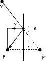
图1利用光线跟踪计算虚顶点的示意图。Figure 1 is a schematic diagram of computing virtual vertices using ray tracing.
图2任意平面反射的示意图。Figure 2. Schematic diagram of arbitrary plane reflection.
图3折射第一种情况--场景在折射体外的示意图。Figure 3 The first case of refraction—a schematic diagram of the scene outside the refractor.
图4折射第二种情况--场景在折射体内的示意图。Figure 4 shows the second case of refraction—a schematic diagram of the scene inside the refractor.
图5折射面相互垂直的三维折射光路图。Figure 5 is a three-dimensional refraction light path diagram in which the refraction planes are perpendicular to each other.
图6球面反射的光路示意图。Figure 6 Schematic diagram of the optical path of spherical reflection.
图7球面折射的光路示意图。Figure 7 Schematic diagram of the optical path of spherical refraction.
图8确定球面的入射点和出射点示意图。Fig. 8 is a schematic diagram of determining the incident point and the outgoing point of the spherical surface.
图9方盒子(a)及其虚物体(b)示意图。Figure 9 is a schematic diagram of a square box (a) and its virtual object (b).
图10为算法1预处理框图。Figure 10 is a block diagram of Algorithm 1 preprocessing.
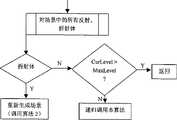
图11为算法2平面折射体或反射体产生虚场景的程序流程框图。Fig. 11 is a block diagram of the procedure for generating a virtual scene by a planar refractor or reflector in Algorithm 2.
图12为算法3视点位置改变时重新计算虚场景的程序流程框图。Fig. 12 is a flow chart of the procedure for recalculating the virtual scene when the viewpoint position of Algorithm 3 changes.
图13为算法4实时绘制和显示的程序流程框图。Fig. 13 is a program flow diagram of real-time drawing and display of Algorithm 4.
具体实施方式Detailed ways
1、基本思想1. Basic idea
如图1所示,光线L从视点A出发,经过折射和反射后到达V点,这是光线跟踪的基本思路。然而给定任意一点V,要准确地得到从视点A出发经过折射到达V点的光线L’,在理论上却是很难计算的,因为折射问题一般是非线性的。As shown in Figure 1, light L starts from viewpoint A and reaches point V after refraction and reflection. This is the basic idea of ray tracing. However, given any point V, it is theoretically difficult to accurately obtain the ray L' from the viewpoint A to the point V through refraction, because the refraction problem is generally nonlinear.
当一条L经过若干次反射或折射,与某一物体的平面M相交于V点时,与传统光线跟踪算法不同,我们不是利用光照模型计算对应象素点的颜色值,而是计算点V的光学映射虚顶点V’。假设光线L经过若干次反射或折射到达V时,经过的路径的长度总和为:d=d1+d2+Λ+d5When a piece of L passes through several reflections or refractions and intersects the plane M of an object at point V, unlike the traditional ray tracing algorithm, we do not use the illumination model to calculate the color value of the corresponding pixel point, but calculate the color value of the point V Optically map the virtual vertex V'. Assume that when the ray L reaches V after several reflections or refractions, the sum of the lengths of the paths passed is: d=d1 +d2 +Λ+d5
则虚顶点V’的计算公式为:
对于被反射或折射的多面体,我们首先计算出每个顶点的虚顶点,然后根据拓扑关系依次将虚顶点连接成虚物体的边,最终形成反射或折射的光学映射虚物体(简称虚物体)。例如一个方盒子,见图9(a),其顶点P1,P2,...,P8的虚顶点依次为P′1,p′2,...,P′8,则我们可以得到该方盒子对应的虚物体,如图9(b)所示。在显示图形时,将这些虚物体投影到反射或折射表面上。这个过程可以递归地进行,从而得到与光线跟踪类似的图像效果。为了得到高质量的真实感图像,被反射或折射的平面的尺寸不能太大,否则应当将平面细分成更小的矩形或三角形。对于场景中被反射或折射的曲面物体,则应当先将曲面离散成若干小平面,用多面体近似表示曲面物体。For the reflected or refracted polyhedron, we first calculate the virtual vertex of each vertex, and then connect the virtual vertices to form the edges of the virtual object in turn according to the topological relationship, and finally form a reflective or refracted optically mapped virtual object (virtual object for short). For example, a square box, see Fig. 9(a), the virtual vertices of its vertices P1 , P2 , ..., P8 are P′1 , p′2 , ..., P′8 in sequence, then we can Get the virtual object corresponding to the square box, as shown in Figure 9(b). Project these virtual objects onto reflective or refractive surfaces when displaying graphics. This process can be done recursively, resulting in image effects similar to ray tracing. In order to obtain high-quality realistic images, the size of the reflected or refracted plane should not be too large, otherwise the plane should be subdivided into smaller rectangles or triangles. For the surface object that is reflected or refracted in the scene, the surface should be discretized into several small planes first, and the surface object should be approximated by a polyhedron.
2、虚顶点的计算公式2. Calculation formula of virtual vertices
对于平面反射问题,我们可以采用类似光束跟踪算法的思想计算各个顶点的虚顶点:For the plane reflection problem, we can use an idea similar to the beam tracing algorithm to calculate the virtual vertices of each vertex:
假设有一个过点R=[Vx,Vy,Vz,1]T的平面,如图2所示,其单位法矢量为N=[a,b,c,0]T,NTN=1,其平面方程为Suppose there is a plane passing through the point R=[Vx , Vy , Vz , 1]T , as shown in Figure 2, its unit normal vector is N=[a, b, c, 0]T , NT N =1, its plane equation is
ax+by+cz+d=0ax+by+cz+d=0
其中,d=-NT R,V为视点。Among them, d=-NT R, V is the viewpoint.
三维场景中的任意一个点P=[Px,Py,Pz,1]T相对于该平面作反射变换后到达P′=[P′x,P′y,P′z,1]T。根据几何关系,可以得到:Any point P=[Px , Py , Pz , 1]T in the three-dimensional scene reaches P′=[P′x , P′y , P′z , 1]T after reflection transformation relative to the plane . According to the geometric relationship, we can get:
P′=TmPP'=Tm P
其中,
P′是P点的反射虚顶点。P' is the reflection virtual vertex of point P.
折射问题比平面反射问题要复杂得多。平面折射体的非线性折射有两种情况:物体在折射体外(如图3所示)和物体在折射体内(见图4)两种。下面我们分别予以讨论。Refraction problems are much more complicated than planar reflection problems. There are two cases of nonlinear refraction of a plane refractor: the object is outside the refractor (as shown in Figure 3) and the object is inside the refractor (see Figure 4). Let's discuss them separately below.
1)二维平面折射1) Two-dimensional plane refraction
(a)物体在折射体外(a) The object is outside the refractor
如图3所示,V是视点,P是场景中任意选取的一点,它在折射体的外面,P′是与P对应的虚顶点。求其虚物体的公式推导如下:As shown in Figure 3, V is the viewpoint, P is an arbitrarily selected point in the scene, which is outside the refractor, and P′ is the virtual vertex corresponding to P. The formula for finding its virtual object is derived as follows:
已知:w1,w2,w3,h,令η=Sinα/Sinβ=η2/η1,ξ=1+w3/w1,根据几何关系,可得Given: w1 , w2 , w3 , h, let η=Sinα/Sinβ=η2 /η1 , ξ=1+w3 /w1 , according to the geometric relationship, we can get
Ad4+Bd3+Cd2+Dd+E=0 (1)Ad4 +Bd3 +Cd2 +Dd+E=0 (1)
其中,in,
A=(1-η2)ξ2,A=(1-η2 )ξ2 ,
B=2η2hξ-2hξ,B=2η2 hξ-2hξ,
C=h2+w22-η2h2-w12η2ξ2,C=h2 +w22 -η2 h2 -w12 η2 ξ2 ,
D=2η2hξw12,D=2η2 hξw12 ,
E=-w12η2h2。E=-w12 η2 h2 .
从(1)式中可以解出d。根据d的值,然后可以计算出折射光线和折射平面的交点I1和I2,从而求出虚顶点P′。From (1) formula can solve d. From the value of d, the intersection points I1 and I2 of the refracted ray and the refracted plane can then be calculated, thereby finding the virtual vertex P'.
虚顶点P′求解过程如下:The solution process of the virtual vertex P' is as follows:
(1)连接V和P,求出VP与平面的交点U:
其中,该平面的方程为C0x+C1y+C2z+C3=0,另外,C=(C0,C1,C2)T;Wherein, the equation of the plane is C0 x+C1 y+C2 z+C3 =0, in addition, C=(C0 , C1 , C2 )T ;
(2)Q=V-w1N;
同理,可以求出I2。Similarly, I2 can be calculated.
令l=|V-I1|+|I1-I2|+|I2-P|,则P点的虚顶点
我们用光线跟踪的方法产生了两组点,然后用上面的公式,反算I1,显然,如果I1相同,则I2也相同,具体的结果如下表所示。
(b)物体在折射体内(b) The object is inside the refractor
如鱼缸中的鱼,物体(鱼)是在折射体(鱼缸)内面。这种情况的计算公式应该与第一钟情况是不同的。如图4所示,图中V是视点,P是场景中任意选取的点,它在折射体内部,P′是P对应的虚顶点。类似地,我们可以根据几何关系得到如下一元四次方程:Like the fish in the fish tank, the object (fish) is inside the refracting body (fish tank). The calculation formula for this case should be different from the first case. As shown in Figure 4, V in the figure is the viewpoint, P is an arbitrarily selected point in the scene, which is inside the refractor, and P′ is the virtual vertex corresponding to P. Similarly, we can get the following one-variable quartic equation according to the geometric relationship:
Ad4+Bd3+Cd2+Dd+E=0 (2)Ad4 +Bd3 +Cd2 +Dd+E=0 (2)
其中,in,
A=η2-1,A=η2 -1,
B=-2hA,B=-2hA,
C=h2A+η2w12-w22,C=h2 A+η2 w12 -w22 ,
D=-2η2hw12,D=-2η2 hw12 ,
E=w12η2h2。E=w12 η2 h2 .
从(2)式中可以解出d,然后便可以计算出折射光线和折射平面的交点I,从而求出虚顶点P′。虚顶点P′求解过程如下:From formula (2), d can be solved, and then the intersection point I of the refracted ray and the refracted plane can be calculated, so as to obtain the virtual vertex P'. The solution process of the virtual vertex P' is as follows:
(1)连接V和P,VP与镜平面相交于U,U可照搬前面的公式得到;(1) Connect V and P, VP intersects the mirror plane at U, and U can be obtained by copying the previous formula;
(2)Q=V-w1N;
我们用光线跟踪的方法产生了两组点,然后用上面的公式,反算出交点I。具体的结果如下表所示。
(c)解的选取(c) Selection of solutions
显然,(1)式和(2)式都是多解的方程,它们都至多有4个实根。因此,解方程后,将要对解的结果进行选择。根据光学的原理,光在介质中从一点到达另一点时,将选择最短路径传播。这样,我们连接视点V和场景中的点P,得到一条直线,离该直线最近的解,就是我们所求的点。Obviously, both equations (1) and (2) are multi-solution equations, and they both have at most 4 real roots. Therefore, after solving the equation, a selection will be made on the result of the solution. According to the principle of optics, when light travels from one point to another in a medium, it will choose the shortest path to propagate. In this way, we connect the viewpoint V and the point P in the scene to get a straight line, and the solution closest to the straight line is the point we are looking for.
2)三维平面折射2) Three-dimensional plane refraction
如图5,已知:视点V,场景中任意选取的点P,折射率η,AD=a,VA=z,PF=b,
由Snell折射定律和几何关系,我们就可以得到下面的两个方程:From Snell's law of refraction and geometric relations, we can get the following two equations:
根据上面的两个方程可以求出x和y,然后由x、y以及z和折射率η的值就可以依次算出I1和I2的三维坐标,从而得到P的虚顶点P’的位置。According to the above two equations, x and y can be obtained, and then the three-dimensional coordinates of I1 and I2 can be calculated sequentially from the values of x, y, z and the refractive index η, so as to obtain the position of the virtual vertex P' of P.
(3)和(4)式是一个二元4次非线性方程组,为了提高计算速度,我们采用下面的方法进行近似处理:(3) and (4) are a binary quadruple nonlinear equation system, in order to improve the calculation speed, we use the following method for approximate processing:
首先,用下式计算出d:f0+f1d+f2d2+f3d3+f4d4=0,忽略d的高阶(>2)项,得First, use the following formula to calculate d: f0 +f1 d+f2 d2 +f3 d3 +f4 d4 =0, ignoring the high-order (>2) terms of d, we get
f0+f1d+f2d2=0,f0 +f1 d+f2 d2 =0,
其中,
在上面的3个式子当中,
然后将d代入下式,便可以计算出当x=0时y的值,我们把它记为y0,即Then substituting d into the following formula can calculate the value of y when x=0, we record it as y0 , that is
y0=a-(0.5+d)。y0 =a-(0.5+d).
通常d是一个很小的量,|d|≤0.5;在上面的计算中,我们忽略了d的高阶(≥3)项,如果保留d的更高阶(3、4阶)项,可以提高计算精度,但是这也会使计算量略有增加。将(4)式在x=0点展开并作线性近似:Usually d is a very small quantity, |d|≤0.5; in the above calculation, we ignore the higher-order (≥3) items of d, if we keep the higher-order (3, 4th) items of d, we can Improve calculation accuracy, but this will also slightly increase the amount of calculation. Expand the formula (4) at x=0 and make a linear approximation:
y=y0+y1x,y=y0 +y1 x,
其中,
将y=y0+y1x代入(3)式,得
从上式中求出x,并将x的值代入式(4)并求解一个关于y的四次方程,该方程经过整理为:Find x from the above formula, and substitute the value of x into formula (4) and solve a quartic equation about y, which is organized as:
H4y4+H3y3+H2y2+H1y+H0=0,H4 y4 +H3 y3 +H2 y2 +H1 y+H0 =0,
其中,in,
H4=e2(2-η2),H4 =e2 (2-η2 ),
H3=-2aex(2-η2),H3 =-2aex(2-η2 ),
H2=a2x2(2-η2)+e2(1-η2)(x2+z2)-b2x2,H2 =a2 x2 (2-η2 )+e2 (1-η2 )(x2 +z2 )-b2 x2 ,
H1=-2aex(1-η2)(x2+z2),H1 =-2aex(1-η2 )(x2 +z2 ),
H0=a2x2(1-η2)(x2+z2)。H0 =a2 x2 (1-η2 )(x2 +z2 ).
再由x、y和z以及η可以计算出点I1和I2的三维坐标,从而求出虚顶点P′。Then the three-dimensional coordinates of points I1 and I2 can be calculated from x, y, z and η, so as to obtain the virtual vertex P'.
由式(3)和式(4)组成的方程组来求解x和y的时候,还有另一种方案:在前面得到y0后,将(3)式在x=0点展开并作线性近似,得到:When solving x and y by the equation system composed of formula (3) and formula (4), there is another scheme: after obtaining y0 in the front, expand the formula (3) at x=0 and make a linear Approximately, we get:
y=y0+y1x,y=y0 +y1 x,
其中,
然后,将y=y0+y1x代入(4)式,整理得到Then, substituting y=y0 +y1 x into the formula (4), we get
T4x4+T3x3+T2x2+T1x+T0=0,T4 x4 +T3 x3 +T2 x2 +T1 x+T0 = 0,
其中

在后面的计算实验中采用的是前一种方案。The former scheme is adopted in the subsequent calculation experiments.
具体计算I1、I2及虚顶点P’的过程如下::The specific calculation process of I1 , I2 and virtual vertex P' is as follows:
a).求I1a). Find I1
设物体上的点是P,视点是V,入射面外法向量n1,出射面外法向量n2,入射面与出射面垂直,n1,n2是单位向量。局部坐标系的基是ex,ey,ez,其中ey=nz,ex=-n1,ey叉乘ez,再单位化可得ex。Suppose the point on the object is P, the viewpoint is V, the normal vector outside the incident plane n1 , the normal vector outside the exit plane n2 , the incident plane is perpendicular to the exit plane, n1 and n2 are unit vectors. The basis of the local coordinate system is ex , ey , ez , where ey = nz , ex = -n1 , ey is cross-multiplied by ez , and then unitized to obtain ex .
计算出的x,y,z是局部坐标系下的坐标。设dx,dy,dz是I1点相对于视点的偏移量,有:The calculated x, y, z are the coordinates in the local coordinate system. Let dx, dy, dz be the offset of point I1 relative to the viewpoint, there are:
dx=xex,dx=xex ,
dy=yey,dy=yey ,
dz=zez,dz=zez ,
则I1=V+dx+dy+dz。Then I1 =V+dx+dy+dz.
b).求I2b). Find I2
已知入射光线方向矢量IN=I1-V,折射面法矢量n1,折射率η,可计算折射光线方向矢量OUT。由折射光线上一点I1以及其方向,和出射面法向量n2及面上一点,可以求出折射光线与出射平面的交点I2。我们可以给出I2的公式如下:
其中
c).求P’c). Find P'
从视点到物点,光线走过的距离是d=‖V-I1‖I1-I2‖+‖I2-P‖,于可以得到虚顶点P’的计算公式:
我们用光线跟踪的方法产生了两组点,然后用上面的公式,反算I1,显然,如果I1相近,则I2也相近。具体的结果如下表所示,其中ε为相对误差,即:用近似公式反算的虚顶点P’到精确的虚顶点p’的距离与视点到虚顶点的距离之比We use ray tracing to generate two sets of points, and then use the above formula to inversely calculate I1 . Obviously, if I1 is similar, then I2 is also similar. The specific results are shown in the following table, where ε is the relative error, that is, the ratio of the distance from the virtual vertex P' to the exact virtual vertex p' calculated by the approximate formula and the distance from the viewpoint to the virtual vertex
ε=|P′-p′|/|V-p′|。
3)球面反射和折射3) Spherical reflection and refraction
(1)球面反射(1) spherical reflection
已知:视点V,场景中任意选取的点P,设反射球的半径为r,球心在0点,如图6所示。令a=|V-P|,b=|V-O|,c=|O-P|。It is known: the viewpoint V, the point P randomly selected in the scene, the radius of the reflective sphere is r, and the center of the sphere is at point 0, as shown in Figure 6. Let a=|V-P|, b=|V-O|, c=|O-P|.
根据几何光学原理可以得到:According to the principle of geometric optics, we can get:
2bcxyzcos(α+β)=bcxysin2(α+β)-b2y2z-c2x2z (5)2bcxyzcos(α+β)=bcxysin2 (α+β)-b2 y2 zc2 x2 z (5)
x(r2+y2-c2)=y(x2+r2-b2) (6)x(r2 +y2 -c2 )=y(x2 +r2 -b2 ) (6)
其中,z=(a2-(x-y)2)/(4abc)。Wherein, z=(a2 −(xy)2 )/(4abc).
取视点V为坐标原点,视点到球心0的距离为单位长度。从(6)式可以解出y,它可以看成是x的函数。将y在x=b-r处作泰勒展开,并取线性近似Take the viewpoint V as the coordinate origin, and the distance from the viewpoint to the center of the sphere 0 as the unit length. From (6) formula can solve y, it can regard as the function of x. Take Taylor expansion of y at x=b-r and take a linear approximation
y=A+Bx, (7)y=A+Bx,
其中,
将(7)代入(5)式,可以得到如下四次方程:Substituting (7) into (5), the following quartic equation can be obtained:
x(A+Bx)[a2-(x-A-Bx)2]cos(α+β)=x(A+Bx)[a2 -(xA-Bx)2 ]cos(α+β)=
2bcx(A+Bx)sin2(α+β)-[b2(A+Bx)2+c2x2][(a2-(x-A-Bx)2]/(2bc),(8)2bcx(A+Bx)sin2 (α+β)-[b2 (A+Bx)2 +c2 x2 ][(a2 -(xA-Bx)2 ]/(2bc), (8)
解出x,然后代入(7)可以求出y,从而计算出虚顶点P’。Solve x, and then substitute into (7) to find y, so as to calculate the virtual vertex P'.
下面介绍如何计算虚顶点P’:The following describes how to calculate the virtual vertex P':
I.由于V,0,P三点在一个平面上,我们以0点为原点,平面VP0的法向量N=[Nx,Ny,Nz]T为z轴,以0P为y轴,0P×N为x轴,建立局部坐标系。这样我们可以得到从世界坐标系到局部坐标系的转换矩阵:
其中,wx=Nx,wy=Ny,wz=Nz;Among them, wx =Nx , wy =Ny , wz =Nz ;
ux=vywz-wyvz,uy=wxvz-vxwz,uz=vxwy-wxvy;ux =vy wz -wy vz , uy =wx vz -vx wz , uz =vx wy -wx vy ;
vx、vy和vz分别是单位矢量(P-O)/|P-O|的三个坐标分量;vx , vy and vz are the three coordinate components of the unit vector (PO)/|PO| respectively;
x,y分别为球面上的点I到视点V和场景中的点P之间的距离:x=|V-I|,y=|I-P|;应用公式I=T.LI便可把LI从局部坐标系变换为世界坐标系下的坐标。x and y are respectively the distances from point I on the sphere to the viewpoint V and the point P in the scene: x=|VI|, y=|IP|; applying the formula I=TLI can transform LI from the local coordinates system into coordinates in the world coordinate system.
II.在局部坐标系中,分别以0,V,P为圆心,R(球的半径),x,y为半径做三个圆,分别记为c1,c2,c3。II. In the local coordinate system, make three circles with 0, V, and P as the centers, R (the radius of the ball), x, and y as the radii, and record them as c1 , c2 , and c3 .
III.求出c1和c2的两个交点p1,p3,c1和c3的两个交点p3,p4。分别计算p1p3,p1p4,p2p3和p2P4的距离,取距离最小的一对点坐标的平均值,即为球面上点I在局部坐标系上的坐标,记为LI[LIx,LIy,Pz,1]T。应用公式I=T·LI将LI的局部坐标变换成世界坐标系下的坐标,结果记为I。IV.计算
我们用光线跟踪的方法产生了两组点,然后用上面的公式,反算I1和I2。具体的结果如下表所示。
(2)球面折射(2) spherical refraction
如图7所示,球的半径为r,根据几何光学可以得到:
Q2=-A-2BC0;Q2 =-A-2BC0 ;
Q3=-B;Q3 =-B;
U0=Q0C02;U0 =Q0 C02 ;
U1=2Q0C0+Q1C02;U1 =2Q0 C0 +Q1 C02 ;
U2=Q0+2Q1C0+Q2C02;U2 =Q0 +2Q1 C0 +Q2 C02 ;
U3=Q1+2Q2C0+Q3C02;U3 =Q1 +2Q2 C0 +Q3 C02 ;
U4=Q2+2Q3C0;U4 =Q2 +2Q3 C0 ;
R0=Q0U0;R0 =Q0 U0 ;
R1=Q0U1+Q1U0;R1 =Q0 U1 +Q1 U0 ;
R2=Q0U2+Q1U1+Q2U0;R2 =Q0 U2 +Q1 U1 +Q2 U0 ;
R3=Q0U3+Q1U2+Q2U1+Q3U0;R3 =Q0 U3 +Q1 U2 +Q2 U1 +Q3 U0 ;
R4=Q0U4+Q1U3+Q2U2+Q3U1;R4 =Q0 U4 +Q1 U3 +Q2 U2 +Q3 U1 ;
P0=(a2+r2-C02)(b2+r2-A2);P0 =(a2 +r2 -C02 )(b2 +r2 -A2 );
P1=-2AB(a2+r2-C02)-2C0(b2+r2-A2);P1 =-2AB(a2 +r2 -C02 )-2C0 (b2 +r2 -A2 );
P2=-B2(a2+r2-C02)+4C0AB-(b2+r2-A2);P2 =-B2 (a2 +r2 -C02 )+4C0 AB-(b2 +r2 -A2 );
P3=2C0B2+2AB;P3 =2C0 B2 +2AB;
P4=BB;P4 =BB;
T0=C3C02P0-C5S0+C02;T0 =C3 C02 P0 -C5 S0 +C02 ;
T1=C3(C02P1+2C0P0)-C5S1-C6S0+2C0;T1 =C3 (C02 P1 +2C0 P0 )-C5 S1 -C6 S0 +2C0 ;
T2=C3(C02P2+2C0P1+P0)-C5S2-C6S1-C7S0+1;T2 =C3 (C02 P2 +2C0 P1 +P0 )-C5 S2 -C6 S1 -C7 S0 +1;
T3=C3(C02P3+2C0P2+P1)-C5S3-C6S2-C7S1;T3 =C3 (C02 P3 +2C0 P2 +P1 )-C5 S3 -C6 S2 -C7 S1 ;
T4=C3(C02P4+2C0P3+P2)-C5S4-C6S3-C7S2;T4 =C3 (C02 P4 +2C0 P3 +P2 )-C5 S4 -C6 S3 -C7 S2 ;
从(13)式可以计算出t,将t代入(11)和(12)式即可分别求出x和y,这样就可以求出虚顶点P’。t can be calculated from formula (13), and x and y can be obtained by substituting t into formulas (11) and (12), so that the virtual vertex P' can be obtained.
确定I1和I2的方法:Method to determine I1 and I2 :
得到x和y后,分别以V和P为圆心,x和y为半径画圆,在折射平面里和球面分别交于I1′,I1″和I2′,I2″,见图8。球面的入射点I1取自I1′和I1″中的某一个,出射点I2取自I2′和I2″中的某一个。也就是说,I1和I2有四种可能的取法。此时,我们将应用折射定律,选取出我们所要的那一种可能情况。注意到,如果I1和I2是精确的入射点和出射点,则
最小的那一组I1I2。The smallest set I1 I2 .
下面介绍如何计算虚顶点P’:The following describes how to calculate the virtual vertex P':
I.由于V,O,P,I1,I2五点在一个平面上,我们以O点为原点,平面VPO的法向量N=[Nx,Ny,Nz]T为z轴,以OP为y轴,N×OP为x轴,建立局部坐标系。这样我们可以得到从局部坐标系到世界坐标系的变换矩阵:
其中,in,
wx=Nx,wy=Ny,wz=Nz;wx = Nx , wy = Ny , wz = Nz ;
uz=vywz-wyvz,uy=wxvz-vxwz,uz=vxwy-wxvy;uz =vy wz -wy vz , uy =wx vz -vx wz , uz =vx wy -wx vy ;
vx、vy和vz分别是单位矢量的三个坐标分量。vx , vy and vz are unit vectors The three coordinate components of .
II.应用公式I=T·LI将I1和I2的局部坐标转换成世界坐标系的坐标,结果仍然用I1和I2表示。II. Apply the formula I=T·LI to transform the local coordinates of I1 and I2 into the coordinates of the world coordinate system, and the result is still represented by I1 and I2 .
III.计算
我们用光线跟踪的方法产生了两组点,然后用上面的公式,反算I1和I2。具体的结果如下表所示。
3、算法实现3. Algorithm implementation
算法1:预处理,如图10所示。Algorithm 1: Preprocessing, as shown in Figure 10.
第1步,对场景中的物体构造二叉空间剖分(BSP)树,如果场景中含有球形反射或折射体,则用紧密包容该球的正方体的6个面代替该球参与构造BSP树;The first step is to construct a binary space partition (BSP) tree for the objects in the scene. If the scene contains a spherical reflection or refraction body, replace the sphere with 6 faces of a cube that tightly contains the sphere to participate in the construction of the BSP tree;
第2步,收集场景中所有的反射和折射体,并形成反射和折射体对象表;Step 2, collect all reflection and refraction bodies in the scene, and form a reflection and refraction body object table;
第3步,根据当前的视点,确定反射、折射体表中的各反射、折射体的先后顺序;由于BSP树与视点无关,因而能很快的得到反射、折射体的顺序;Step 3, according to the current viewpoint, determine the order of each reflection and refraction body in the reflection and refraction body table; since the BSP tree has nothing to do with the viewpoint, the order of reflection and refraction bodies can be quickly obtained;
第4步,计算虚顶点并生成所有的虚物体,产生虚场景。Step 4: Calculate virtual vertices and generate all virtual objects to generate a virtual scene.
算法2为平面折射体或反射体产生虚场景,如图11所示。有以下特点:Algorithm 2 generates virtual scenes for plane refractors or reflectors, as shown in Figure 11. Has the following characteristics:
(1)上面的算法是一个递归算法,递归主要是针对场景中的反射、折射体进行的;(1) The above algorithm is a recursive algorithm, and the recursion is mainly for the reflection and refraction objects in the scene;
(2)对于反射体和折射体是统一处理的;(2) The reflector and refractor are treated uniformly;
(3)对于反射体,生成虚场景使用的是反射公式,对应的面片的顶点顺序要改变,即反射虚物体面片的顶点顺序与原来的顺序相反,以便确保平面的外法矢指向正确的方向;(3) For reflectors, the reflection formula is used to generate the virtual scene, and the order of vertices of the corresponding facets needs to be changed, that is, the order of vertices of the facets of the reflection virtual object is reversed from the original order, so as to ensure that the outer normal vector of the plane points correctly the direction of
(4)在任一虚场景中,都要根据视点和BSP树重新确定其中的反射和折射体的顺序,以便后面能够正确地实时显示;(4) In any virtual scene, the order of reflection and refraction bodies in it must be re-determined according to the viewpoint and BSP tree, so that it can be displayed correctly in real time later;
(5)如果场景中的反射或折射体的个数大于1算法的终止条件是递归深度不大于所给定的最大递归深度值;(5) If the number of reflection or refraction objects in the scene is greater than 1, the termination condition of the algorithm is that the recursion depth is not greater than the given maximum recursion depth value;
如果视点发生变化,对于纯反射虚场景,是不用重算的;但对于任意一个折射体及其以后的递归过程中出现的虚场景必须重新计算;下面是视点发生变化时重新计算虚场景的算法:If the viewpoint changes, there is no need to recalculate the pure reflection virtual scene; but for any refraction body and the virtual scene that appears in the subsequent recursive process, it must be recalculated; the following is the algorithm for recalculating the virtual scene when the viewpoint changes :
算法3为视点位置改变时重新计算虚场景,如图12所示。Algorithm 3 recalculates the virtual scene when the viewpoint position changes, as shown in Figure 12.
要实现实时绘制场景,就必须采用硬件加速的办法。这时,我们要用到图形硬件的公用的软件接口OpenGL。前面的虚物体的生成,为我们实时绘制打下了基础。下面是我们使用的实时绘制算法。To achieve real-time rendering of scenes, hardware acceleration must be adopted. At this time, we need to use the common software interface OpenGL of the graphics hardware. The generation of the previous virtual objects laid the foundation for our real-time rendering. Below is the real-time rendering algorithm we use.
算法4为实时绘制和显示,如图13所示。Algorithm 4 is real-time rendering and display, as shown in Figure 13.
Claims (6)
Priority Applications (1)
| Application Number | Priority Date | Filing Date | Title |
|---|---|---|---|
| CN 02130945CN1410948A (en) | 2002-09-23 | 2002-09-23 | Real time light tracing method of non linear refraction and reflection on plane and spherical surfaces |
Applications Claiming Priority (1)
| Application Number | Priority Date | Filing Date | Title |
|---|---|---|---|
| CN 02130945CN1410948A (en) | 2002-09-23 | 2002-09-23 | Real time light tracing method of non linear refraction and reflection on plane and spherical surfaces |
Publications (1)
| Publication Number | Publication Date |
|---|---|
| CN1410948Atrue CN1410948A (en) | 2003-04-16 |
Family
ID=4746520
Family Applications (1)
| Application Number | Title | Priority Date | Filing Date |
|---|---|---|---|
| CN 02130945PendingCN1410948A (en) | 2002-09-23 | 2002-09-23 | Real time light tracing method of non linear refraction and reflection on plane and spherical surfaces |
Country Status (1)
| Country | Link |
|---|---|
| CN (1) | CN1410948A (en) |
Cited By (14)
| Publication number | Priority date | Publication date | Assignee | Title |
|---|---|---|---|---|
| CN101297325A (en)* | 2005-12-29 | 2008-10-29 | 英特尔公司 | Application of interval algorithm for reducing computation time in ray tracking problems |
| CN101359404A (en)* | 2007-07-31 | 2009-02-04 | 英特尔公司 | Real-time luminosity dependent subdivision |
| CN100557638C (en)* | 2006-11-28 | 2009-11-04 | 国际商业机器公司 | Carry out the method and system of ray tracing |
| CN100557637C (en)* | 2006-11-28 | 2009-11-04 | 国际商业机器公司 | Carry out the method and system of ray tracing |
| CN100565471C (en)* | 2007-08-29 | 2009-12-02 | 威盛电子股份有限公司 | Method for recording and playing function call of open graphic library |
| CN100570638C (en)* | 2006-11-28 | 2009-12-16 | 国际商业机器公司 | The method of dispensing work load and image processing system |
| CN101165721B (en)* | 2006-10-17 | 2010-06-02 | 国际商业机器公司 | Ray tracking method and system |
| CN101894390A (en)* | 2010-06-29 | 2010-11-24 | 浙江大学 | A Ray Tracing Method in Non-constant Refractive Index Media |
| CN101918769A (en)* | 2007-10-24 | 2010-12-15 | 伊苏勒有限公司 | Heliostat calibration in a kind of central tower receiver solar power plant and tracking control |
| CN101982838A (en)* | 2010-11-02 | 2011-03-02 | 长春理工大学 | 3D virtual set ray tracking method for accelerating back light source irradiation |
| CN102074041A (en)* | 2010-12-21 | 2011-05-25 | 长春理工大学 | Method for drawing planar caustic effect of 3D virtual scene produced by specular reflection |
| CN101276479B (en)* | 2007-03-29 | 2011-08-31 | 国际商业机器公司 | Image process method and system |
| CN102282591A (en)* | 2008-09-10 | 2011-12-14 | 柯斯提克绘图有限公司 | Ray Tracing System Architecture and Methodology |
| CN101506847B (en)* | 2006-08-22 | 2012-03-28 | 国际商业机器公司 | Methods and systems for partitioning a spatial index |
- 2002
- 2002-09-23CNCN 02130945patent/CN1410948A/enactivePending
Cited By (18)
| Publication number | Priority date | Publication date | Assignee | Title |
|---|---|---|---|---|
| CN101297325B (en)* | 2005-12-29 | 2013-04-24 | 英特尔公司 | Method and device for radio tracking |
| CN101297325A (en)* | 2005-12-29 | 2008-10-29 | 英特尔公司 | Application of interval algorithm for reducing computation time in ray tracking problems |
| CN101506847B (en)* | 2006-08-22 | 2012-03-28 | 国际商业机器公司 | Methods and systems for partitioning a spatial index |
| CN101165721B (en)* | 2006-10-17 | 2010-06-02 | 国际商业机器公司 | Ray tracking method and system |
| CN100557638C (en)* | 2006-11-28 | 2009-11-04 | 国际商业机器公司 | Carry out the method and system of ray tracing |
| CN100557637C (en)* | 2006-11-28 | 2009-11-04 | 国际商业机器公司 | Carry out the method and system of ray tracing |
| CN100570638C (en)* | 2006-11-28 | 2009-12-16 | 国际商业机器公司 | The method of dispensing work load and image processing system |
| CN101276479B (en)* | 2007-03-29 | 2011-08-31 | 国际商业机器公司 | Image process method and system |
| CN101359404A (en)* | 2007-07-31 | 2009-02-04 | 英特尔公司 | Real-time luminosity dependent subdivision |
| CN100565471C (en)* | 2007-08-29 | 2009-12-02 | 威盛电子股份有限公司 | Method for recording and playing function call of open graphic library |
| CN101918769A (en)* | 2007-10-24 | 2010-12-15 | 伊苏勒有限公司 | Heliostat calibration in a kind of central tower receiver solar power plant and tracking control |
| CN101918769B (en)* | 2007-10-24 | 2013-01-16 | 伊苏勒有限公司 | Calibration and tracking control of heliostats in a central tower receiver solar power plant |
| CN102282591A (en)* | 2008-09-10 | 2011-12-14 | 柯斯提克绘图有限公司 | Ray Tracing System Architecture and Methodology |
| CN101894390B (en)* | 2010-06-29 | 2012-07-04 | 浙江大学 | Ray tracing method for non-constant refractive index medium |
| CN101894390A (en)* | 2010-06-29 | 2010-11-24 | 浙江大学 | A Ray Tracing Method in Non-constant Refractive Index Media |
| CN101982838A (en)* | 2010-11-02 | 2011-03-02 | 长春理工大学 | 3D virtual set ray tracking method for accelerating back light source irradiation |
| CN102074041A (en)* | 2010-12-21 | 2011-05-25 | 长春理工大学 | Method for drawing planar caustic effect of 3D virtual scene produced by specular reflection |
| CN102074041B (en)* | 2010-12-21 | 2012-10-10 | 长春理工大学 | Method for drawing planar caustic effect of 3D virtual scene produced by specular reflection |
Similar Documents
| Publication | Publication Date | Title |
|---|---|---|
| CN1410948A (en) | Real time light tracing method of non linear refraction and reflection on plane and spherical surfaces | |
| CN1264122C (en) | Image processing device, method and equipment | |
| CN1343343A (en) | Method and apparatus for processing images | |
| CN1924931A (en) | Video rendering apparatus and method | |
| CN1297945C (en) | Map display system, map data processing apparatus, map display apparatus, and map display method | |
| CN1849608A (en) | Method and program for generating volume data from data represented by boundaries | |
| CN1131495C (en) | Characteristic Information Assignment Method and Device | |
| CN1146805C (en) | Method for communicating and generating computer graphics, animation data, and recording media | |
| CN1404016A (en) | Establishing method of human face 3D model by fusing multiple-visual angle and multiple-thread 2D information | |
| CN100338632C (en) | Marker placement information estimating method and information processing device | |
| CN1855150A (en) | Image processing device, method, program and recording medium | |
| CN101044507A (en) | Image processing method, image processing device and image processing program | |
| CN1491403A (en) | Image processing device, image processing method, storage medium and computer program for non-planar images | |
| CN1272933A (en) | Image processing apparatus and image processing method, program providing medium, and data providing medium | |
| CN1835022A (en) | Generating a 2d model using 3D transition | |
| CN1146244A (en) | Head-mount display and optical system used for the same | |
| CN100341031C (en) | Curve image processor and its processing method | |
| CN1910619A (en) | Three-dimensional video game system | |
| CN1233030A (en) | The method and apparatus of adaptive phong shading | |
| CN1115454A (en) | Image processing device and system using same | |
| CN1598644A (en) | Stereoscopic image display device | |
| CN1747559A (en) | 3D geometric modeling system and method | |
| CN1526098A (en) | Method and system for outputting data related to two-dimensional or three-dimensional geometric entities | |
| CN101046892A (en) | Graphics-rendering apparatus | |
| CN1618087A (en) | Three-dimensional shape display program, three-dimensional shape display method, and three-dimensional shape display device |
Legal Events
| Date | Code | Title | Description |
|---|---|---|---|
| C06 | Publication | ||
| PB01 | Publication | ||
| C10 | Entry into substantive examination | ||
| SE01 | Entry into force of request for substantive examination | ||
| C12 | Rejection of a patent application after its publication | ||
| RJ01 | Rejection of invention patent application after publication |