CN1410216A - Friction welding method - Google Patents
Friction welding methodDownload PDFInfo
- Publication number
- CN1410216A CN1410216ACN01111802ACN01111802ACN1410216ACN 1410216 ACN1410216 ACN 1410216ACN 01111802 ACN01111802 ACN 01111802ACN 01111802 ACN01111802 ACN 01111802ACN 1410216 ACN1410216 ACN 1410216A
- Authority
- CN
- China
- Prior art keywords
- plate
- friction welding
- butt joint
- abutting
- rotary tool
- Prior art date
- Legal status (The legal status is an assumption and is not a legal conclusion. Google has not performed a legal analysis and makes no representation as to the accuracy of the status listed.)
- Granted
Links
Images


Classifications
- B—PERFORMING OPERATIONS; TRANSPORTING
- B61—RAILWAYS
- B61D—BODY DETAILS OR KINDS OF RAILWAY VEHICLES
- B61D17/00—Construction details of vehicle bodies
- B61D17/04—Construction details of vehicle bodies with bodies of metal; with composite, e.g. metal and wood body structures
- B61D17/043—Construction details of vehicle bodies with bodies of metal; with composite, e.g. metal and wood body structures connections between superstructure sub-units
- B—PERFORMING OPERATIONS; TRANSPORTING
- B23—MACHINE TOOLS; METAL-WORKING NOT OTHERWISE PROVIDED FOR
- B23K—SOLDERING OR UNSOLDERING; WELDING; CLADDING OR PLATING BY SOLDERING OR WELDING; CUTTING BY APPLYING HEAT LOCALLY, e.g. FLAME CUTTING; WORKING BY LASER BEAM
- B23K20/00—Non-electric welding by applying impact or other pressure, with or without the application of heat, e.g. cladding or plating
- B23K20/12—Non-electric welding by applying impact or other pressure, with or without the application of heat, e.g. cladding or plating the heat being generated by friction; Friction welding
- B23K20/122—Non-electric welding by applying impact or other pressure, with or without the application of heat, e.g. cladding or plating the heat being generated by friction; Friction welding using a non-consumable tool, e.g. friction stir welding
- B23K20/123—Controlling or monitoring the welding process
- B—PERFORMING OPERATIONS; TRANSPORTING
- B23—MACHINE TOOLS; METAL-WORKING NOT OTHERWISE PROVIDED FOR
- B23K—SOLDERING OR UNSOLDERING; WELDING; CLADDING OR PLATING BY SOLDERING OR WELDING; CUTTING BY APPLYING HEAT LOCALLY, e.g. FLAME CUTTING; WORKING BY LASER BEAM
- B23K20/00—Non-electric welding by applying impact or other pressure, with or without the application of heat, e.g. cladding or plating
- B23K20/12—Non-electric welding by applying impact or other pressure, with or without the application of heat, e.g. cladding or plating the heat being generated by friction; Friction welding
- B23K20/122—Non-electric welding by applying impact or other pressure, with or without the application of heat, e.g. cladding or plating the heat being generated by friction; Friction welding using a non-consumable tool, e.g. friction stir welding
- B23K20/1245—Non-electric welding by applying impact or other pressure, with or without the application of heat, e.g. cladding or plating the heat being generated by friction; Friction welding using a non-consumable tool, e.g. friction stir welding characterised by the apparatus
- B23K20/126—Workpiece support, i.e. backing or clamping
- B—PERFORMING OPERATIONS; TRANSPORTING
- B23—MACHINE TOOLS; METAL-WORKING NOT OTHERWISE PROVIDED FOR
- B23K—SOLDERING OR UNSOLDERING; WELDING; CLADDING OR PLATING BY SOLDERING OR WELDING; CUTTING BY APPLYING HEAT LOCALLY, e.g. FLAME CUTTING; WORKING BY LASER BEAM
- B23K33/00—Specially-profiled edge portions of workpieces for making soldering or welding connections; Filling the seams formed thereby
- B23K33/004—Filling of continuous seams
- E—FIXED CONSTRUCTIONS
- E04—BUILDING
- E04C—STRUCTURAL ELEMENTS; BUILDING MATERIALS
- E04C2/00—Building elements of relatively thin form for the construction of parts of buildings, e.g. sheet materials, slabs, or panels
- E04C2/02—Building elements of relatively thin form for the construction of parts of buildings, e.g. sheet materials, slabs, or panels characterised by specified materials
- E04C2/08—Building elements of relatively thin form for the construction of parts of buildings, e.g. sheet materials, slabs, or panels characterised by specified materials of metal, e.g. sheet metal
- E—FIXED CONSTRUCTIONS
- E04—BUILDING
- E04C—STRUCTURAL ELEMENTS; BUILDING MATERIALS
- E04C2/00—Building elements of relatively thin form for the construction of parts of buildings, e.g. sheet materials, slabs, or panels
- E04C2/30—Building elements of relatively thin form for the construction of parts of buildings, e.g. sheet materials, slabs, or panels characterised by the shape or structure
- E04C2/34—Building elements of relatively thin form for the construction of parts of buildings, e.g. sheet materials, slabs, or panels characterised by the shape or structure composed of two or more spaced sheet-like parts
- E04C2/36—Building elements of relatively thin form for the construction of parts of buildings, e.g. sheet materials, slabs, or panels characterised by the shape or structure composed of two or more spaced sheet-like parts spaced apart by transversely-placed strip material, e.g. honeycomb panels
- E—FIXED CONSTRUCTIONS
- E04—BUILDING
- E04C—STRUCTURAL ELEMENTS; BUILDING MATERIALS
- E04C2/00—Building elements of relatively thin form for the construction of parts of buildings, e.g. sheet materials, slabs, or panels
- E04C2/54—Slab-like translucent elements
- E04C2/543—Hollow multi-walled panels with integrated webs
- B—PERFORMING OPERATIONS; TRANSPORTING
- B23—MACHINE TOOLS; METAL-WORKING NOT OTHERWISE PROVIDED FOR
- B23K—SOLDERING OR UNSOLDERING; WELDING; CLADDING OR PLATING BY SOLDERING OR WELDING; CUTTING BY APPLYING HEAT LOCALLY, e.g. FLAME CUTTING; WORKING BY LASER BEAM
- B23K2101/00—Articles made by soldering, welding or cutting
- B23K2101/04—Tubular or hollow articles
- B23K2101/045—Hollow panels
- Y—GENERAL TAGGING OF NEW TECHNOLOGICAL DEVELOPMENTS; GENERAL TAGGING OF CROSS-SECTIONAL TECHNOLOGIES SPANNING OVER SEVERAL SECTIONS OF THE IPC; TECHNICAL SUBJECTS COVERED BY FORMER USPC CROSS-REFERENCE ART COLLECTIONS [XRACs] AND DIGESTS
- Y10—TECHNICAL SUBJECTS COVERED BY FORMER USPC
- Y10T—TECHNICAL SUBJECTS COVERED BY FORMER US CLASSIFICATION
- Y10T428/00—Stock material or miscellaneous articles
- Y10T428/12—All metal or with adjacent metals
- Y10T428/1234—Honeycomb, or with grain orientation or elongated elements in defined angular relationship in respective components [e.g., parallel, inter- secting, etc.]
- Y—GENERAL TAGGING OF NEW TECHNOLOGICAL DEVELOPMENTS; GENERAL TAGGING OF CROSS-SECTIONAL TECHNOLOGIES SPANNING OVER SEVERAL SECTIONS OF THE IPC; TECHNICAL SUBJECTS COVERED BY FORMER USPC CROSS-REFERENCE ART COLLECTIONS [XRACs] AND DIGESTS
- Y10—TECHNICAL SUBJECTS COVERED BY FORMER USPC
- Y10T—TECHNICAL SUBJECTS COVERED BY FORMER US CLASSIFICATION
- Y10T428/00—Stock material or miscellaneous articles
- Y10T428/12—All metal or with adjacent metals
- Y10T428/12375—All metal or with adjacent metals having member which crosses the plane of another member [e.g., T or X cross section, etc.]
- Y—GENERAL TAGGING OF NEW TECHNOLOGICAL DEVELOPMENTS; GENERAL TAGGING OF CROSS-SECTIONAL TECHNOLOGIES SPANNING OVER SEVERAL SECTIONS OF THE IPC; TECHNICAL SUBJECTS COVERED BY FORMER USPC CROSS-REFERENCE ART COLLECTIONS [XRACs] AND DIGESTS
- Y10—TECHNICAL SUBJECTS COVERED BY FORMER USPC
- Y10T—TECHNICAL SUBJECTS COVERED BY FORMER US CLASSIFICATION
- Y10T428/00—Stock material or miscellaneous articles
- Y10T428/12—All metal or with adjacent metals
- Y10T428/12382—Defined configuration of both thickness and nonthickness surface or angle therebetween [e.g., rounded corners, etc.]
- Y—GENERAL TAGGING OF NEW TECHNOLOGICAL DEVELOPMENTS; GENERAL TAGGING OF CROSS-SECTIONAL TECHNOLOGIES SPANNING OVER SEVERAL SECTIONS OF THE IPC; TECHNICAL SUBJECTS COVERED BY FORMER USPC CROSS-REFERENCE ART COLLECTIONS [XRACs] AND DIGESTS
- Y10—TECHNICAL SUBJECTS COVERED BY FORMER USPC
- Y10T—TECHNICAL SUBJECTS COVERED BY FORMER US CLASSIFICATION
- Y10T428/00—Stock material or miscellaneous articles
- Y10T428/12—All metal or with adjacent metals
- Y10T428/12493—Composite; i.e., plural, adjacent, spatially distinct metal components [e.g., layers, joint, etc.]
- Y—GENERAL TAGGING OF NEW TECHNOLOGICAL DEVELOPMENTS; GENERAL TAGGING OF CROSS-SECTIONAL TECHNOLOGIES SPANNING OVER SEVERAL SECTIONS OF THE IPC; TECHNICAL SUBJECTS COVERED BY FORMER USPC CROSS-REFERENCE ART COLLECTIONS [XRACs] AND DIGESTS
- Y10—TECHNICAL SUBJECTS COVERED BY FORMER USPC
- Y10T—TECHNICAL SUBJECTS COVERED BY FORMER US CLASSIFICATION
- Y10T428/00—Stock material or miscellaneous articles
- Y10T428/19—Sheets or webs edge spliced or joined
- Y10T428/192—Sheets or webs coplanar
- Y—GENERAL TAGGING OF NEW TECHNOLOGICAL DEVELOPMENTS; GENERAL TAGGING OF CROSS-SECTIONAL TECHNOLOGIES SPANNING OVER SEVERAL SECTIONS OF THE IPC; TECHNICAL SUBJECTS COVERED BY FORMER USPC CROSS-REFERENCE ART COLLECTIONS [XRACs] AND DIGESTS
- Y10—TECHNICAL SUBJECTS COVERED BY FORMER USPC
- Y10T—TECHNICAL SUBJECTS COVERED BY FORMER US CLASSIFICATION
- Y10T428/00—Stock material or miscellaneous articles
- Y10T428/24—Structurally defined web or sheet [e.g., overall dimension, etc.]
- Y10T428/24777—Edge feature
Landscapes
- Engineering & Computer Science (AREA)
- Mechanical Engineering (AREA)
- Architecture (AREA)
- Civil Engineering (AREA)
- Structural Engineering (AREA)
- Life Sciences & Earth Sciences (AREA)
- Wood Science & Technology (AREA)
- Pressure Welding/Diffusion-Bonding (AREA)
- Standing Axle, Rod, Or Tube Structures Coupled By Welding, Adhesion, Or Deposition (AREA)
- Laminated Bodies (AREA)
- Connection Of Plates (AREA)
Abstract
Description
Translated fromChinese本发明涉及一种摩擦焊接方法,该方法适用于铝合金有轨机动车及房屋等场合所用镶板的焊接。The invention relates to a friction welding method, which is suitable for welding panels used in aluminum alloy rail vehicles, houses and other occasions.
日本公开专利说明书246863/1990公开了一种采用中空构件的有轨机动车用双表面结构板(镶板),而日本公开专利说明书106661/1994则公开了一种采用蜂窝型镶板一类层状镶板的方案。Japanese Laid-Open Patent Specification 246863/1990 discloses a double-surface structural panel (panel) for rail vehicles using hollow members, while Japanese Laid-Open Patent Specification 106661/1994 discloses a type of layer using a honeycomb panel Shaped paneling scheme.
摩擦焊接是通过旋转某一插入接头区域中的圆杆而实现的,圆杆的旋转可以加热接头区域并使之塑化,从而达到焊接的目的。这种焊接方法适用于对接接头及搭接接头。该工艺在WO 93/10935(同于WO 0615480B1,也同于外国PCT专利申请指定日本而公开的专利文献No.505090/1995号)和期刊(Welding & Metal Fabrication,January1995,pp.13-16)中已有介绍。本发明将解决的问题Friction welding is achieved by rotating a round rod inserted into the joint area. The rotation of the round rod can heat and plasticize the joint area, so as to achieve the purpose of welding. This welding method is suitable for butt joints and lap joints. This process is described in WO 93/10935 (the same as WO 0615480B1, also the same as the patent document No. 505090/1995 published by foreign PCT patent application designating Japan) and periodicals (Welding & Metal Fabrication, January 1995, pp.13-16) has been introduced. Problems to be solved by the present invention
在摩擦焊接中,直接从焊接工具(圆杆)之下挤出的塑化金属会在焊接过程中冲击焊接表面,因而有一下驱力作用在接头区域上。这样,在将该焊接方法运用于双表面结构板(镶板)时,该下驱力将使接头区域的焊接材料向下流动并使接头区域变形。如此便不可能获得满意的焊接质量。In friction welding, the plasticized metal extruded directly under the welding tool (round rod) impacts the welding surface during the welding process, so there is a driving force acting on the joint area. Thus, when the welding method is applied to double-surface structural panels (panels), the downward driving force will cause the welding material in the joint area to flow downward and deform the joint area. This makes it impossible to obtain satisfactory welding quality.
双表面结构板(镶板)包含由挤压铝合金制成的中空构件以及蜂窝型镶板。这类镶板的连接可以由MIG焊接法及TIG焊接法实现。而用摩擦焊接进行这类连接则可能使接头区域向下弯曲,或者使接头区域内的材料因焊接过程中产生的下驱力而被迫向下流动。Double-faced structural panels (panels) consist of hollow members made of extruded aluminum alloys and honeycomb-type panels. The joining of such panels can be achieved by MIG welding as well as TIG welding. Making these types of connections with friction welding may cause the joint area to bend downwards, or material within the joint area to be forced to flow downward due to the downward driving force generated during the welding process.
本发明人通过大量试验发现了上述问题。The present inventors discovered the above-mentioned problems through extensive experiments.
本发明的目的是,在对中空构件进行摩擦焊时,能抑制连接部位的变形并获得良好的焊接。It is an object of the present invention to obtain good welding while suppressing deformation of a connection portion during friction welding of a hollow member.
为实现上述目的,按本发明提供了这样一种一种摩擦焊接方法,其中:使一个第二构件的端部分别与一第一构件的两个角部的切口部分对接,以形成两个对接部分,上述切口部分朝沿所述第一构件厚度方向的外侧和第一构件的端部侧张开;以及,在所述第一构件和第二构件在所述对接部分之一位置处受到支承的情况下,通过把一个旋转工具从所述外侧插在另一个所述对接部分处,对上述前一个对接部分进行摩擦焊。In order to achieve the above object, the present invention provides such a friction welding method, wherein: the end of a second member is respectively abutted with the cutout portions of the two corners of a first member to form two butt joints. part, the above-mentioned notch part is opened toward the outer side in the thickness direction of the first member and the end side of the first member; and, the first member and the second member are supported at a position of one of the butted parts In the case of , friction welding is performed on the aforementioned one butted portion by inserting a rotary tool at the other said butted portion from the outer side.
图1是本发明某一实施例的垂直截面。Fig. 1 is a vertical section of an embodiment of the present invention.
图2是图1在摩擦焊之后的垂直截面。Figure 2 is a vertical section of Figure 1 after friction welding.
图3是本发明另一实施例的垂直截面。Fig. 3 is a vertical section of another embodiment of the present invention.
图4是图3在摩擦焊之后的垂直截面。Figure 4 is a vertical section of Figure 3 after friction welding.
图5是本发明又一实施例的垂直截面。Fig. 5 is a vertical section of yet another embodiment of the present invention.
图6是图5的摩擦焊之后的垂直截面。FIG. 6 is a vertical section after friction welding of FIG. 5 .
图7是本发明再一实施例的垂直截面。Fig. 7 is a vertical section of another embodiment of the present invention.
图8是图7在摩擦焊之后的垂直截面。Figure 8 is a vertical section of Figure 7 after friction welding.
图9是表示如本发明又一实施例所述摩擦焊过程的垂直截面。Fig. 9 is a vertical section showing a friction welding process according to yet another embodiment of the present invention.
图10是本发明又一实施例的垂直截面。Fig. 10 is a vertical section of yet another embodiment of the present invention.
图11是本发明又一实施例的垂直截面。Fig. 11 is a vertical section of yet another embodiment of the present invention.
图12是本发明又一实施例的垂直截面。Fig. 12 is a vertical section of yet another embodiment of the present invention.
图13是本发明又一实施例的垂直截面。Fig. 13 is a vertical section of yet another embodiment of the present invention.
图14是本发明又一实施例的垂直截面。Fig. 14 is a vertical section of yet another embodiment of the present invention.
图15是有轨机动车的车身透视图。Fig. 15 is a perspective view of the body of the rail vehicle.
在图1所示实施例中,作为镶板的中空构件31,32之间具有对接式的接头结构。中空构件31、32宽度方向的端部设有垂直板36,36。垂直板36,36在焊接之前被直接置于旋转工具50的下方。垂直板36,36彼此面对面接触。即便彼此分离,二者间的距离也很小并大约为1mm。凸部52的中心轴线位于二垂直板36,36之间界面的延伸面上。垂直板36,36的刚度足以承受前面提及的下驱力。垂直板36垂直于另外两块板件33,34。中空构件31,32由铝合金挤压成形。中空构件31的上表面和下表面与中空构件32上对应的上表面及下表面齐平。亦即中空构件31和32具有相等的厚度。下文所述的实施例也是如此。在摩擦焊接中,旋转工具50大径部分51与小径凸部52之间的边缘53位于中空构件31,32上表面的上方。标识符35表示用来连接两块板件33,34并以桁架结构形式设置的若干个构件。两个中空构件31,32都具有两边对称的端部。中空构件31,32被装在某一底架(图中未加表示)上并被固死。底架也位于垂直板36,36下方。In the embodiment shown in FIG. 1 , there is a butt joint structure between the
摩擦焊接的实施方式是:使工具50旋转,将凸部52插入中空构件31,32的接头区域并使凸部52沿接头区域移动。凸部52的转动中心轴线位于两个垂直板36,36之间。The embodiment of friction welding is that the
图2表示两个经过摩擦焊接之后的镶板。标识符45表示焊接后形成的焊道。焊道45的宽度中心位于垂直板36,36接合线的延长线上。焊道45位于垂直板36,36厚度范围内的某一区域内。焊道45深度取决于旋转工具50底端凸部52插入接头区域中的高度。Figure 2 shows two panels after friction welding.
在这种结构中,垂直于板件33,34的垂直板36,36支承着摩擦焊接过程中产生的垂向力,所以接头区域不会发生弯曲,由此可获得图2所示的令人满意的接头。制做垂直板36时应使之尽可能地垂直于板33,34。In this structure, the
垂直板36上可以打孔,以减轻重量,下文所述实施例也是如此。The
焊接中空构件底侧时可将其上下翻转。Hollow components can be turned upside down when welding the underside.
在图3所示实施例中,某一中空构件31的端部设有垂直板36,而另一中空构件32的对应端部却没有。在中空构件31的垂直板36上,其垂直方向上的角部被做出切口,由此可嵌接中空构件32上突出体38,38的端部。该切口部分沿中空构件31的厚度方向及厚度的垂直方向(朝向中空构件32一侧)张开。当突出体38被放置(嵌套)于切口部分中时,二者之间留有一定的间隙,尽管在图中看来是彼此相接触的。这些构件的前端之间(即突出体38,38与角边33a,34a之间)也留有间隙。两个中空构件31,32及垂直板36上表面一侧的对接接头部分直接位于旋转工具50中心轴线的下方。焊接工具50凸部52的旋转中心轴线位于垂直板36厚度中心线的延长线中。也就是说,板件33(34)和板件34(33)的接头区域位于垂直板36厚度中心线的延长线上。从板件33,34延伸至切口部分的角边33b,34b位于垂直板36厚度中心线的延长线上。考虑到角边33b,34b与突出体38之间的间隙,角边33b,34b位置应稍稍偏向垂直板36厚度中心线延长线的左侧。垂直板36的刚度应足以承受下驱力。突出体38前端与中空构件31之间的水平间隙同于图1所示情形。焊接工具50凸部52的高度与突出体38的厚度大致相等。塑性流动区域在突出体38下侧扩展,逐渐形成大于凸部25直径的区域,由此完成两个中空构件31,32的摩擦焊接。对于突出体38下侧与垂直板36间的接触区域来说,其下侧也必须分布着按上述方式形成的摩擦焊缝。In the embodiment shown in FIG. 3 , the end of one
图4表示焊接后的接头状况。焊道45的成形特点在于:其宽度中心位于垂直板36,36厚度中心线的延长线上。Figure 4 shows the condition of the joint after welding. The forming feature of the
为了能承受垂向力,必须使工具50的旋转中心轴线位于垂直板36,36厚度中心线的延长线上。为使左右中空构件31,32的接合量相同,角边33b,34b也必须位于垂直板36,36厚度中心线的延长线上。作为优选方案,工具50的凸部52位于垂直板36厚度延长线的范围内,而垂直板36的厚度又取决于垂向力的大小、凸部52的位置以及垂直板36的强度。因此,垂直板36厚度小于凸部52直径的情况是存在的。鉴于旋转工具50及角边33b,34b可能存在的位置误差,应使角边33b,34b定位于垂直板36厚度延长线的范围内,而且凸部52也应至少有一部分位于该范围内。这种设置可使垂直板36至少承担一部分垂向力,从而基本实现对接头变形的结构性预防。如此便可获得满意的焊接效果。就焊道45来说,即使其尺寸略大于凸部52,上述结论仍然是有效的。对于其它实施例来说也同样如此。In order to be able to bear the vertical force, the center axis of rotation of the
与图1所示的情形相比,这种接头结构即使在突出体38与中空构件31之间间隙较大时,也能够使接头区域的表面凹陷减至最低程度。这一特点可以使该接头获得较好的外观质量,并可减少喷漆时的腻子用量。其原因在于,两个构件之间的间隙终止于与突出体38厚度相等的深度位置上。还需要指出:这种接头结构可以减轻重量。此外,由于两个中空构件彼此嵌接,所以二者在高度方向上的定位也易于实现。Compared with the situation shown in FIG. 1, this joint structure can minimize the surface depression in the joint area even when the gap between the
中空构件31的端部具有两边对称的形状。中空构件32也是两边对称的。另外,中空构件31的一端可以是图3所示形状,而其另一端则可做成图3所示中空构件32端部的形状。The end portion of the
在图5所示实施例中,中空构件31上切口部分的角边33b,34b下侧实际上并没有直接设置垂直板36。垂直板36的右端位于角边33b,34b的延伸部分上。工具50的旋转中心轴线对准该延伸部分。中空构件31的端部应具有足以承受垂向力的刚度,为此,可以增厚接头处的下侧突出体37并增大从突出体37的前端部至垂直板36的过渡圆角尺寸。象以上图3所示的实施例一样,另一中空构件32的突出体38可嵌入突出体37的切口部分中。第二个中空构件32的突出体38附近设有用来连接上侧板件33和下侧板件34的垂直板36。对于这种设置来说,即使切口部分的角边正下方没有垂直板36,接头区域中也不会出现缺陷。不过需要指出,焊道45下侧设有板件31的垂直板36。图6表示了焊接之后的状况。In the embodiment shown in FIG. 5 , the lower sides of the
在图5所示实施例中,中空构件32的板件36是可以去除的。In the embodiment shown in Figure 5, the
图7表示作为图5所示实施例之改型的另一个实施例,其中,两个中空构件31,32的接头区域设有向外伸出的凸出部分37a,38a。这可以使接头区域增厚。两个凸出部分37a,38a的高度是相等的。除垂直板36和凸部37稍薄以外,该结构的其它部分同于图5所示结构。FIG. 7 shows another embodiment as a modification of the embodiment shown in FIG. 5, in which the joint region of the two
对这种结构来说,如果两个凸出部分37a,38a之间在焊接前存在间隙,那么在焊接时就需要用凸出部分37a,38a的材料填充该间隙,由此可改进外观质量并降低腻子用量。For this structure, if there is a gap between the two protruding
在普通焊缝中,下驱力使材料41向下流动,焊道中的凹陷部分便对应着材料41流失所形成的空隙。在图7所示接头结构中,旋转工具使突出部分37a,38a塑化并迫使其弥补材料41的流失空隙。这样便避免了形成凹陷,从而获得满意的焊接头。图8表示焊接后的焊道45形状。焊接之后如果存在多余部分,可如图所示将其切除。In a common weld, the downward driving force causes the material 41 to flow downward, and the concave portion in the weld bead corresponds to the void formed by the loss of the material 41 . In the joint configuration shown in FIG. 7 , the rotating tool plasticizes the
设置凸出部分37a,38a的做法也适用于图1,3,5及下文所述的各实施例。The method of providing the protruding
图9表示另一实施例,该实施例只允许从一侧对在上下表面进行焊接。中空构件31,32底侧的端部设有突出体34a,34a,该突出体与下侧板件34,34齐平并显著地伸向对面的中空构件一侧。两个突出体34a,34a的前端彼此大致相接触。上侧板件33,33的前端比下侧板件34,34的前端靠后一些。上侧板件33,33的前端通过垂直板36,36与下侧板件34,34相接。垂直板36,36接在下侧板件34的中部。垂直板36,36的顶部设有可容纳某一连接件60的切口部分39,39。当连接件60被装在切口部分39,39上时,其上表面可与上侧板件33,33的上表面齐平。两个垂直板36,36间的距离应尽可能小,但也应足以保证旋转工具50的插入。垂直板36,36与切口部分39间的关系同于对图5和图7所示实施例的描述。Figure 9 shows another embodiment which only allows welding on the upper and lower surfaces from one side only. The ends of the bottom sides of the
以下介绍焊接过程。在图9(A)所示状态下,用旋转工具50焊接下侧板件的前端。此时,包含板件34,34之接头区域在内的中空构件31,32被装在底架上。底架的上表面(即焊道背后)为平面。旋转工具50之凸部52的高度小于板件34,34的厚度。这种设计可保证底面在焊接后仍然平整。因此,底面一侧无疑可以作为有轨机动车或房屋结构的外表面(该外表面是指未装装饰板的表面)。通常,摩擦焊接区的上表面(在边缘部分51)是不易于平整的。The welding process is described below. In the state shown in FIG. 9(A), the front end of the lower plate is welded with the
此后,如图9(B)所示,将连接件60装在两个中空构件31,32之间,连接件60具有T形垂直截面。当连接件60的两端被装在切口部分39,39上时,垂直部分61的底端与下侧板件上的焊道之间将形成一定的间隙。垂直部分61可被省去。Thereafter, as shown in FIG. 9(B), a connecting
接着,如图9(C)所示,用旋转工具50对连接件60与中空构件31之间的接头部分进行摩擦焊接。旋转工具50无需与图9(A)中所用的工具相同。Next, as shown in FIG. 9(C), the joint portion between the
然后,如图9(D)所示,用旋转工具50对连接件60与中空构件32之间的接头部分进行摩擦焊接。Then, as shown in FIG. 9(D), the joint portion between the
上述方法允许从一侧进行焊接,因而除去了翻转操作。除去翻转操作的优点在于省去了翻转及定位操作所需的工时,并省去了翻转装置,而且装配精度也进而得以改善。The method described above allows welding from one side, thus eliminating the flipping operation. The advantage of eliminating the overturning operation is that man-hours required for the overturning and positioning operations are saved, and the overturning device is eliminated, and the assembly accuracy is further improved.
图10表示另一实施例,其中采用了对中空构件51,52的上下两侧同时进行摩擦焊接的方法。用于下侧的旋转工具50a在上侧所用焊接工具50的垂直下方布置。第二个焊接工具50a的凸部52朝向上方。两个彼此相向的焊接工具50,50a在进行摩擦焊接时以相同的速度运动。标识符70,70表示底架(台面)。工具50和50a的旋转中心轴线位于同一条直线上,中空构件31,32的接头区域也在该直线上。Fig. 10 shows another embodiment in which a method of simultaneously friction welding the upper and lower sides of the
采用这种布置可以使第二工具50a的旋转中心轴线定位于第一工具50旋转中心轴线的延长线上,二者间的力学平衡有助于在较短的时间内比较小的变形完成接头的焊接。此外,由于无需翻转中空构件31,32,焊接过程将在短时间内完成,而且接头的变形也比较小。With this arrangement, the rotation center axis of the
该实施例也适用于其它实施例。This embodiment is also applicable to other embodiments.
上述各实施例以中空构件为待焊接的镶板。下文的实施例将介绍适用于蜂窝型镶板的摩擦焊接方法。如图11所示,蜂窝型镶板80a,80b包括以下部分:两块表面板件81,82;具有蜂窝状内腔的芯骨构件83;以及沿表面板件81,82边缘布置的边缘构件84,其中,芯骨构件83和边缘构件84被纤焊在表面板件81,82上,从而形成一个整体结构。表面板件81,82,芯骨构件83及边缘构件84均由铝合金制成。边缘构件84为挤压成形件并具有矩形截面。该矩形截面上每一条边的厚度都大于表面板件81,82的厚度。类似于图1所示情形,对于相互接触的两个边缘构件84,84来说,二者垂直边的厚度是相等的。两个蜂窝型镶板80a,80b具有相等的厚度。In the above-mentioned embodiments, the hollow member is used as the panel to be welded. The following examples will describe a friction welding method suitable for honeycomb type panels. As shown in Figure 11, the
图11所示实施例对应于图1所示实施例。旋转工具50凸部52的高度大于表面板件81,82的厚度。这样便于对表面板件81,82和边缘构件84,84进行焊接。加在镶板80a,80b上的载荷主要通过边缘构件84传递。对已完工的镶板80a,80b可进行装配及摩擦焊接。The embodiment shown in FIG. 11 corresponds to the embodiment shown in FIG. 1 . The height of the
图12所示实施例对应于图3所示实施例。蜂窝型镶板80a的边缘构件84具有大致为矩形的截面,且角边处设有切口。而蜂窝型镶板80b的边缘构件84则象一个开口朝向蜂窝型镶板80a的管道。边缘构件84的开口端被接在蜂窝型镶板80a之边缘构件84的切口部分上。The embodiment shown in FIG. 12 corresponds to the embodiment shown in FIG. 3 . The
对应于图5的蜂窝型镶板可按同样方法制造。Honeycomb panels corresponding to Figure 5 can be produced in the same way.
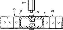
图13表示对应于图7的又一个实施例。在装配好两个蜂窝型镶板80a,80b之后,将板件86放在表面板件81,81上并临时性地将其焊在表面板件81,81上。板件86可对塑化并流出的材料加以补偿。图12所示蜂窝型镶板80a之边缘构件的垂直部分被去掉了,垂向力被边缘构件84的水平部分及其周围其它部分承受。FIG. 13 shows yet another embodiment corresponding to FIG. 7 . After the two
图14表示本发明的另一个实施例。在图13及其之前的各实施例中,镶板具有两个表面(表面板件),而图14所示实施例中的镶板91,92实际上只有一个表面(表面板件94,94)。摩擦焊接在镶板91,92毗连端的两个位置上进行,即具有表面板件94的外侧以及没有表面板件的内侧。因此,内侧的接头部分设有较窄的表面板件(表面板件93,93)。较窄的表面板件93,93由垂直板96,96支承。在该例中,垂直板96也大体垂直于表面板件93,94。与图7所示情形类似,表面板件93,94上也设有凸出部分37a,38a。表面板件94,94具有若干个以一定间距分布的加强肋(板件)95,95。这些加强肋95的截面为T形。加强肋95的顶面与接头部分的表面板件93的顶面齐平。可在顶面焊上加固构件(如支柱),也可将顶面作为物体的安装座。此外,顶面93,93也可以充当控制焊接工具50高度的基准座。工具50的移动载体可以沿着表面板件93,93运动。由于表面板件93和94的存在,可以说镶板91,92也是一个双表面结构。镶板91,92是挤压成形构件。Fig. 14 shows another embodiment of the present invention. In Fig. 13 and its previous embodiments, the panels had two surfaces (surface panels), whereas the
图14表示了彼此相对的两个镶板91及92在其接头部分处的垂直板96,96,其结构类似于图1,不过对此也可以采取图3,5及7所示的方式,亦即将垂直板彼此装配起来。Figure 14 shows the
图15表示该实施例在有轨机动车车身结构上的应用实例。该车身结构具有侧部车身101,车顶结构102,底板结构103以及外于纵向端部的角形结构104。侧部车身101和车顶结构102使用了长边指向车辆纵向的镶板31,32,80a,80b,91,92。侧部车身101与车顶结构102之间以及侧部车身101与底板结构103之间的接合由MIG焊接法实现。车顶结构102及侧部车身101一般做成弧形截面。当用镶板91,92做侧部车身101时,具有垂直板96和加强肋96的一侧朝向车辆内侧,而且支柱由加固构件构成。Fig. 15 shows the application example of this embodiment on the rail vehicle body structure. The body structure has a
图9所示镶板31和32可以以镜像布置方式配合使用。将各镶板之伸出板件34的端部置于另一镶板上板件33的切口部分39处。这样将无需使用连接件60,而且可以对上下两侧的接头区域同时进行摩擦焊接。如图7所示,镶板33,34上可设置凸出部分。The
Claims (23)
Translated fromChineseApplications Claiming Priority (2)
| Application Number | Priority Date | Filing Date | Title |
|---|---|---|---|
| JP6249196 | 1996-03-19 | ||
| JP62491/1996 | 1996-03-19 |
Related Parent Applications (1)
| Application Number | Title | Priority Date | Filing Date |
|---|---|---|---|
| CNB971034974ADivisionCN1203954C (en) | 1996-03-19 | 1997-03-18 | Friction Stir Welding Method |
Related Child Applications (2)
| Application Number | Title | Priority Date | Filing Date |
|---|---|---|---|
| CNB2004101046719ADivisionCN1322242C (en) | 1996-03-19 | 1997-03-18 | Structure for friction welding |
| CNB2004101046013ADivisionCN1322241C (en) | 1996-03-19 | 1997-03-18 | Friction welding method and structure body formed by friction welding |
Publications (2)
| Publication Number | Publication Date |
|---|---|
| CN1410216Atrue CN1410216A (en) | 2003-04-16 |
| CN1203957C CN1203957C (en) | 2005-06-01 |
Family
ID=13201704
Family Applications (20)
| Application Number | Title | Priority Date | Filing Date |
|---|---|---|---|
| CNB011114983AExpired - Fee RelatedCN1165403C (en) | 1996-03-19 | 1997-03-18 | Components for friction welding |
| CNB2004101046013AExpired - Fee RelatedCN1322241C (en) | 1996-03-19 | 1997-03-18 | Friction welding method and structure body formed by friction welding |
| CNB2006100943947AExpired - Fee RelatedCN100441935C (en) | 1996-03-19 | 1997-03-18 | panel structure |
| CNB2004101046719AExpired - Fee RelatedCN1322242C (en) | 1996-03-19 | 1997-03-18 | Structure for friction welding |
| CNB2006100998206AExpired - Fee RelatedCN100475411C (en) | 1996-03-19 | 1997-03-18 | Friction welding method and structure using the friction welding method |
| CNB2006100943932AExpired - Fee RelatedCN100531997C (en) | 1996-03-19 | 1997-03-18 | Panel Construct |
| CN2006100943928AExpired - Fee RelatedCN1880002B (en) | 1996-03-19 | 1997-03-18 | Friction Stir Welding Method |
| CNB971034974AExpired - Fee RelatedCN1203954C (en) | 1996-03-19 | 1997-03-18 | Friction Stir Welding Method |
| CNB2004100949164AExpired - Fee RelatedCN1310732C (en) | 1996-03-19 | 1997-03-18 | Friction welding method |
| CNB991084934AExpired - Fee RelatedCN1208165C (en) | 1996-03-19 | 1999-06-18 | Structure and vehicle manufacturing method |
| CNB011118059AExpired - Fee RelatedCN1208166C (en) | 1996-03-19 | 2001-03-16 | Structural body mfg. method and structural body |
| CNB011118024AExpired - Fee RelatedCN1203957C (en) | 1996-03-19 | 2001-03-16 | Friction welding method and structure using the friction welding method |
| CNB011118075AExpired - Fee RelatedCN1199756C (en) | 1996-03-19 | 2001-03-16 | Structural member for friction welding |
| CNB011118032AExpired - Fee RelatedCN1211180C (en) | 1996-03-19 | 2001-03-16 | Hollow structural member for friction welding |
| CNB011118016AExpired - Fee RelatedCN1203956C (en) | 1996-03-19 | 2001-03-16 | Friction welding method |
| CNB011114967AExpired - Fee RelatedCN1192847C (en) | 1996-03-19 | 2001-03-16 | Friction welding method and structural body |
| CNB011118067AExpired - Fee RelatedCN1208167C (en) | 1996-03-19 | 2001-03-16 | Structural member for friction welding |
| CN01111497APendingCN1322650A (en) | 1996-03-19 | 2001-03-16 | Structural body of railway stock |
| CN011118040AExpired - Fee RelatedCN1216713C (en) | 1996-03-19 | 2001-03-16 | Friction welding method |
| CNB011114991AExpired - Fee RelatedCN1192848C (en) | 1996-03-19 | 2001-03-16 | Method of friction welding and structural body |
Family Applications Before (11)
| Application Number | Title | Priority Date | Filing Date |
|---|---|---|---|
| CNB011114983AExpired - Fee RelatedCN1165403C (en) | 1996-03-19 | 1997-03-18 | Components for friction welding |
| CNB2004101046013AExpired - Fee RelatedCN1322241C (en) | 1996-03-19 | 1997-03-18 | Friction welding method and structure body formed by friction welding |
| CNB2006100943947AExpired - Fee RelatedCN100441935C (en) | 1996-03-19 | 1997-03-18 | panel structure |
| CNB2004101046719AExpired - Fee RelatedCN1322242C (en) | 1996-03-19 | 1997-03-18 | Structure for friction welding |
| CNB2006100998206AExpired - Fee RelatedCN100475411C (en) | 1996-03-19 | 1997-03-18 | Friction welding method and structure using the friction welding method |
| CNB2006100943932AExpired - Fee RelatedCN100531997C (en) | 1996-03-19 | 1997-03-18 | Panel Construct |
| CN2006100943928AExpired - Fee RelatedCN1880002B (en) | 1996-03-19 | 1997-03-18 | Friction Stir Welding Method |
| CNB971034974AExpired - Fee RelatedCN1203954C (en) | 1996-03-19 | 1997-03-18 | Friction Stir Welding Method |
| CNB2004100949164AExpired - Fee RelatedCN1310732C (en) | 1996-03-19 | 1997-03-18 | Friction welding method |
| CNB991084934AExpired - Fee RelatedCN1208165C (en) | 1996-03-19 | 1999-06-18 | Structure and vehicle manufacturing method |
| CNB011118059AExpired - Fee RelatedCN1208166C (en) | 1996-03-19 | 2001-03-16 | Structural body mfg. method and structural body |
Family Applications After (8)
| Application Number | Title | Priority Date | Filing Date |
|---|---|---|---|
| CNB011118075AExpired - Fee RelatedCN1199756C (en) | 1996-03-19 | 2001-03-16 | Structural member for friction welding |
| CNB011118032AExpired - Fee RelatedCN1211180C (en) | 1996-03-19 | 2001-03-16 | Hollow structural member for friction welding |
| CNB011118016AExpired - Fee RelatedCN1203956C (en) | 1996-03-19 | 2001-03-16 | Friction welding method |
| CNB011114967AExpired - Fee RelatedCN1192847C (en) | 1996-03-19 | 2001-03-16 | Friction welding method and structural body |
| CNB011118067AExpired - Fee RelatedCN1208167C (en) | 1996-03-19 | 2001-03-16 | Structural member for friction welding |
| CN01111497APendingCN1322650A (en) | 1996-03-19 | 2001-03-16 | Structural body of railway stock |
| CN011118040AExpired - Fee RelatedCN1216713C (en) | 1996-03-19 | 2001-03-16 | Friction welding method |
| CNB011114991AExpired - Fee RelatedCN1192848C (en) | 1996-03-19 | 2001-03-16 | Method of friction welding and structural body |
Country Status (6)
| Country | Link |
|---|---|
| US (24) | US6581819B1 (en) |
| EP (18) | EP0797043B1 (en) |
| JP (7) | JP2000202652A (en) |
| KR (13) | KR100445140B1 (en) |
| CN (20) | CN1165403C (en) |
| DE (17) | DE69739569D1 (en) |
Cited By (2)
| Publication number | Priority date | Publication date | Assignee | Title |
|---|---|---|---|---|
| CN101032784B (en)* | 2006-03-08 | 2011-05-11 | 萨帕铝型材股份公司 | Adjustable overlap joint and structure produced thereby |
| CN111692172A (en)* | 2020-06-19 | 2020-09-22 | 中车唐山机车车辆有限公司 | Connecting piece, headwall and carriage |
Families Citing this family (180)
| Publication number | Priority date | Publication date | Assignee | Title |
|---|---|---|---|---|
| CN1165403C (en)* | 1996-03-19 | 2004-09-08 | 株式会社日立制作所 | Components for friction welding |
| JP3897391B2 (en)* | 1997-03-25 | 2007-03-22 | 昭和電工株式会社 | Friction stir welding method for metal joining members |
| GB9713209D0 (en)* | 1997-06-20 | 1997-08-27 | British Aerospace | Friction welding metal components |
| JP3070735B2 (en) | 1997-07-23 | 2000-07-31 | 株式会社日立製作所 | Friction stir welding method |
| JP3589863B2 (en) | 1997-07-23 | 2004-11-17 | 株式会社日立製作所 | Structure and friction stir welding method |
| SE9704800D0 (en)* | 1997-12-19 | 1997-12-19 | Esab Ab | Device for welding |
| US6051325A (en)* | 1997-12-23 | 2000-04-18 | Mcdonnell Douglas Corporation | Joining of machined sandwich assemblies by friction stir welding |
| US6745929B1 (en)* | 1998-06-16 | 2004-06-08 | Hitachi, Ltd. | Method of manufacturing structural body and structural body |
| JP3420502B2 (en)* | 1998-06-16 | 2003-06-23 | 株式会社日立製作所 | Structure |
| US6045028A (en) | 1998-07-17 | 2000-04-04 | Mcdonnell Douglas Corporation | Integral corrosion protection of friction-welded joints |
| AU733140B2 (en)* | 1998-09-29 | 2001-05-10 | Hitachi Limited | A friction stir welding method |
| JP3459193B2 (en) | 1999-05-26 | 2003-10-20 | 株式会社日立製作所 | Method of repairing friction stir welding and method of manufacturing railway vehicle |
| TW460346B (en)* | 1999-05-28 | 2001-10-21 | Hitachi Ltd | A manufacturing method of a structure body and a manufacturing apparatus of a structure body |
| TW464576B (en) | 1999-05-28 | 2001-11-21 | Hitachi Ltd | A structure body and a manufacturing method of a structure body |
| JP3481501B2 (en) | 1999-05-28 | 2003-12-22 | 株式会社日立製作所 | Structure and method of manufacturing the same |
| JP2000343245A (en)* | 1999-05-31 | 2000-12-12 | Hitachi Ltd | How to make a structure |
| TW449519B (en) | 1999-05-31 | 2001-08-11 | Hitachi Ltd | A manufacturing method of a structure body |
| DE19948441A1 (en)* | 1999-10-08 | 2001-04-12 | Abb Research Ltd | Device for joining metal sheets, working with heat generating rotating ceramic pin |
| JP3459210B2 (en) | 1999-11-24 | 2003-10-20 | 株式会社日立製作所 | Friction stir welding method |
| JP3538357B2 (en)* | 2000-01-24 | 2004-06-14 | 株式会社日立製作所 | Friction stir welding method |
| AU757401B2 (en)* | 2000-01-27 | 2003-02-20 | Hitachi Limited | Structure body |
| JP3552978B2 (en) | 2000-01-27 | 2004-08-11 | 株式会社日立製作所 | Hollow profile |
| JP3571601B2 (en)* | 2000-02-21 | 2004-09-29 | 株式会社日立製作所 | Friction stir welding method |
| JP3589930B2 (en)* | 2000-02-25 | 2004-11-17 | 株式会社日立製作所 | Friction stir welding method |
| JP3575748B2 (en) | 2000-03-06 | 2004-10-13 | 株式会社日立製作所 | Friction stir welding method |
| MXPA02010936A (en) | 2000-05-08 | 2004-09-06 | Univ Brigham Young | Friction stir weldin of metal matrix composites, ferrous alloys, non ferrous alloys, and superalloys using a superabrasive tool. |
| JP3781099B2 (en)* | 2000-06-02 | 2006-05-31 | トヨタ自動車株式会社 | Hollow product, fluid processing system, and method for joining hollow members |
| US6352193B1 (en) | 2000-08-01 | 2002-03-05 | General Electric Company | Apparatus for joining electrically conductive materials |
| JP2002086281A (en)* | 2000-09-13 | 2002-03-26 | Hitachi Ltd | Friction stir welding method |
| JP3818084B2 (en)* | 2000-12-22 | 2006-09-06 | 日立電線株式会社 | Cooling plate and manufacturing method thereof, and sputtering target and manufacturing method thereof |
| JP3761786B2 (en) | 2001-01-17 | 2006-03-29 | 株式会社日立製作所 | Friction stir welding method and apparatus |
| JP3751215B2 (en)* | 2001-04-16 | 2006-03-01 | 株式会社日立製作所 | Friction stir welding method |
| JP3725043B2 (en)* | 2001-04-25 | 2005-12-07 | 株式会社日立製作所 | Rail vehicle |
| US6732901B2 (en) | 2001-06-12 | 2004-05-11 | Brigham Young University Technology Transfer Office | Anvil for friction stir welding high temperature materials |
| US7152909B2 (en)* | 2001-06-22 | 2006-12-26 | East Manufacturing Corporation | Trailer and trailer body construction and extruded panel for same |
| JP2003095097A (en) | 2001-09-25 | 2003-04-03 | Hitachi Ltd | Rail vehicle |
| JP3725057B2 (en) | 2001-09-25 | 2005-12-07 | 株式会社日立製作所 | Rail vehicle |
| DE20200646U1 (en)* | 2002-01-17 | 2003-06-05 | Horst Witte Entwicklungs- und Vertriebs-KG, 21369 Nahrendorf | Sandwich panel for making workpiece clamping devices, comprises hollow profiles joined together by friction welding |
| DE20202108U1 (en)* | 2002-02-13 | 2003-06-26 | Horst Witte Entwicklungs- und Vertriebs-KG, 21369 Nahrendorf | Sandwich panel to build up workpiece fixtures |
| DE10226526A1 (en)* | 2002-06-14 | 2003-08-07 | Daimler Chrysler Ag | Running gear frame has interconnected frame sections with at least one frame section seam as a friction stir welded seam which extends three-dimensionally, and at least two frame sections are differently constructed |
| JP4647179B2 (en)* | 2002-09-11 | 2011-03-09 | 株式会社日立製作所 | Processing method |
| JP2006518671A (en) | 2003-01-30 | 2006-08-17 | スミス インターナショナル、インコーポレテッド | Out-of-position friction stir welding of high melting point materials |
| US7430888B2 (en)* | 2003-04-25 | 2008-10-07 | Showa Denko K.K. | Tubular metal body, method of producing same, liner for pressure vessel and method of producing same |
| WO2004101205A2 (en) | 2003-05-05 | 2004-11-25 | Smith International, Inc. | Applications of friction stir welding using a superabrasive tool |
| US6893594B2 (en)* | 2003-06-20 | 2005-05-17 | Kuei Yung Wang Chen | Extruded window and door composite frames |
| US6933057B2 (en)* | 2003-07-17 | 2005-08-23 | The Boeing Company | Friction stir welded assembly and method of forming a friction stir welded assembly |
| US7225968B2 (en) | 2003-08-04 | 2007-06-05 | Sii Megadiamond, Inc. | Crack repair using friction stir welding on materials including metal matrix composites, ferrous alloys, non-ferrous alloys, and superalloys |
| US7494040B2 (en)* | 2003-09-25 | 2009-02-24 | Sii Megadiamond, Inc. | Friction stir welding improvements for metal matrix composites, ferrous alloys, non-ferrous alloys, and superalloys using a superabrasive tool |
| US7225967B2 (en) | 2003-12-16 | 2007-06-05 | The Boeing Company | Structural assemblies and preforms therefor formed by linear friction welding |
| US7398911B2 (en)* | 2003-12-16 | 2008-07-15 | The Boeing Company | Structural assemblies and preforms therefor formed by friction welding |
| GB0329898D0 (en)* | 2003-12-23 | 2004-01-28 | Airbus Uk Ltd | Welding process for large structures |
| KR100608712B1 (en)* | 2004-01-06 | 2006-08-03 | 삼성전자주식회사 | Image data display device and display method |
| CA2492185A1 (en)* | 2004-01-08 | 2005-07-08 | Tecton Products | Pultruded building product |
| US20050166516A1 (en)* | 2004-01-13 | 2005-08-04 | Valinge Aluminium Ab | Floor covering and locking systems |
| US20050199372A1 (en)* | 2004-03-08 | 2005-09-15 | Frazer James T. | Cold plate and method of making the same |
| US20050210820A1 (en)* | 2004-03-24 | 2005-09-29 | Shinmaywa Industries, Ltd. | Frame and method for fabricating the same |
| US8186561B2 (en) | 2004-03-24 | 2012-05-29 | Megastir Technologies, LLC | Solid state processing of hand-held knife blades to improve blade performance |
| JP4485846B2 (en)* | 2004-05-11 | 2010-06-23 | 株式会社日立製作所 | Structure block manufacturing method and manufacturing apparatus |
| US7520099B2 (en)* | 2004-05-17 | 2009-04-21 | Tecton Products | Pultruded building product and system |
| US20050262791A1 (en)* | 2004-05-17 | 2005-12-01 | Todd Pringle | Siding and building product |
| US20060049234A1 (en)* | 2004-05-21 | 2006-03-09 | Flak Richard A | Friction stirring and its application to drill bits, oil field and mining tools, and components in other industrial applications |
| US20100078224A1 (en) | 2004-05-21 | 2010-04-01 | Smith International, Inc. | Ball hole welding using the friction stir welding (fsw) process |
| US7188686B2 (en)* | 2004-06-07 | 2007-03-13 | Varco I/P, Inc. | Top drive systems |
| JP4695355B2 (en)* | 2004-07-15 | 2011-06-08 | 新日本製鐵株式会社 | Boom / arm member for construction machine with excellent weld fatigue strength and method for manufacturing the same |
| US7841504B2 (en)* | 2004-09-21 | 2010-11-30 | The Boeing Company | Apparatus and system for welding self-fixtured preforms and associated method |
| CN100584510C (en)* | 2004-10-05 | 2010-01-27 | Sii米加钻石公司 | Expandable mandrel for use in friction stir welding and method of providing the mandrel |
| FR2879548B1 (en)* | 2004-12-17 | 2007-02-16 | Alstom Transport Sa | PANEL ASSEMBLY FOR THE CONSTRUCTION OF A RAIL VEHICLE BOX AND METHOD THEREOF |
| KR100780019B1 (en)* | 2005-02-01 | 2007-11-27 | 가부시끼가이샤 히다치 세이사꾸쇼 | Friction Stir Welding |
| US7473475B1 (en)* | 2005-05-13 | 2009-01-06 | Florida Turbine Technologies, Inc. | Blind weld configuration for a rotor disc assembly |
| JP5010117B2 (en)* | 2005-07-20 | 2012-08-29 | 株式会社神戸製鋼所 | Aluminum extruded hollow panel for automobile and manufacturing method thereof |
| BRPI0520507A2 (en)* | 2005-08-19 | 2009-05-12 | Airbus Espana Sl | composite material beams with bulb |
| US9266191B2 (en) | 2013-12-18 | 2016-02-23 | Aeroprobe Corporation | Fabrication of monolithic stiffening ribs on metallic sheets |
| US9511445B2 (en) | 2014-12-17 | 2016-12-06 | Aeroprobe Corporation | Solid state joining using additive friction stir processing |
| US9511446B2 (en) | 2014-12-17 | 2016-12-06 | Aeroprobe Corporation | In-situ interlocking of metals using additive friction stir processing |
| US8632850B2 (en) | 2005-09-26 | 2014-01-21 | Schultz-Creehan Holdings, Inc. | Friction fabrication tools |
| US8550326B2 (en) | 2005-10-05 | 2013-10-08 | Megastir Technologies Llc | Expandable mandrel for use in friction stir welding |
| US8056797B2 (en) | 2005-10-05 | 2011-11-15 | Megastir Technologies | Expandable mandrel for use in friction stir welding |
| DE102005048001B4 (en)* | 2005-10-06 | 2007-06-14 | Euro-Composites S.A., Zone Industrielle | connecting element |
| JP4531671B2 (en)* | 2005-10-12 | 2010-08-25 | 株式会社神戸製鋼所 | Hollow panel and manufacturing method thereof |
| US7353978B2 (en)* | 2005-10-13 | 2008-04-08 | The Boeing Company | Method of making tailored blanks using linear friction welding |
| JP4266024B2 (en)* | 2006-03-28 | 2009-05-20 | 株式会社日立製作所 | Rail vehicle, manufacturing method thereof, and hollow shape material used therefor |
| GB0616324D0 (en)* | 2006-08-16 | 2006-09-27 | Airbus Uk Ltd | A cover panel for an aircraft wing and a method of forming thereof |
| US20080047222A1 (en)* | 2006-08-23 | 2008-02-28 | Lockheed Martin Corporation | Friction stir welding process having enhanced corrosion performance |
| FR2907040B1 (en) | 2006-10-13 | 2009-06-26 | Alstom Transport Sa | METHOD FOR ASSEMBLING A STRUCTURE COMPRISING AN EXTERIOR AND AN INTERIOR CONSISTING OF A PLURALITY OF DOUBLE-SKIN ELEMENTS, SUCH AS A RAILWAY VEHICLE CASE, AND STRUCTURE OBTAINED |
| JP4882004B2 (en)* | 2006-11-03 | 2012-02-22 | 株式会社東洋鋼鐵 | Manufacturing apparatus and manufacturing method for reinforcing frame for display panel using aluminum alloy extruded material |
| KR100832241B1 (en)* | 2006-11-03 | 2008-05-28 | 주식회사동양강철 | Reinforcement frame for display panel using aluminum alloy extrusion and its manufacturing method |
| JP5094140B2 (en)* | 2006-11-09 | 2012-12-12 | 日野自動車株式会社 | Member joint structure |
| JP4972417B2 (en)* | 2006-12-15 | 2012-07-11 | 日野自動車株式会社 | Member joining method and structure |
| FR2912490B1 (en) | 2007-02-09 | 2010-10-29 | Alcan Rhenalu | METAL COMPOSITE PANEL AND METHOD OF MANUFACTURE |
| DE102007010262A1 (en)* | 2007-03-02 | 2008-09-04 | Siemens Ag | Lightweight structures, for use in e.g. vehicle bodywork, comprise sandwich panel with heat-sensitive core between two outer sheets, connectors at either end of the panel being welded to it using friction stir welding |
| US20080230584A1 (en)* | 2007-03-19 | 2008-09-25 | The Boeing Company | Method for Manufacturing a Workpiece by Friction Welding to Reduce the Occurrence of Abnormal Grain Growth |
| CN103722288B (en)* | 2007-06-14 | 2016-03-16 | 日本轻金属株式会社 | Bonding method |
| US20080311421A1 (en)* | 2007-06-15 | 2008-12-18 | United Technologies Corporation | Friction stir welded structures derived from AL-RE-TM alloys |
| US7624907B2 (en)* | 2007-06-15 | 2009-12-01 | Cyril Bath Company | Linear friction welding apparatus and method |
| US20080308197A1 (en)* | 2007-06-15 | 2008-12-18 | United Technologies Corporation | Secondary processing of structures derived from AL-RE-TM alloys |
| US20080308610A1 (en)* | 2007-06-15 | 2008-12-18 | United Technologies Corporation | Hollow structures formed with friction stir welding |
| US20100068550A1 (en)* | 2007-06-15 | 2010-03-18 | United Technologies Corporation | Hollow structures formed with friction stir welding |
| CN101772395B (en)* | 2007-08-10 | 2013-01-16 | 日本轻金属株式会社 | Joining method and method for manufacturing joined structure |
| WO2009022507A1 (en)* | 2007-08-10 | 2009-02-19 | Nippon Light Metal Company, Ltd. | Joining method and method of manufacturing joint structure |
| US7856790B2 (en)* | 2007-10-10 | 2010-12-28 | Tecton Products, Llc | Pultruded building product |
| US8376453B2 (en)* | 2007-11-30 | 2013-02-19 | Kyoraku Co., Ltd. | Hollow double-walled panel and interior panel for vehicle made using same |
| US8079126B2 (en)* | 2008-01-25 | 2011-12-20 | Pratt & Whitney Rocketdyne, Inc. | Friction stir welded bladder fuel tank |
| US20090223957A1 (en) | 2008-03-06 | 2009-09-10 | Hmt,Inc. | Welded full contact floating roof and method |
| US20090235608A1 (en)* | 2008-03-19 | 2009-09-24 | Jan Kosny | Support structures formed from triangular elements |
| US7762447B2 (en) | 2008-03-20 | 2010-07-27 | Ut-Battelle, Llc | Multiple pass and multiple layer friction stir welding and material enhancement processes |
| US8100316B2 (en)* | 2008-05-29 | 2012-01-24 | Airbus Operations Gmbh | Method for joining aircraft fuselage elements by friction stir welding (fsw) |
| US10252376B2 (en)* | 2009-03-03 | 2019-04-09 | U-Haul International, Inc. | Welded lap joint with corrosive-protective structure |
| DE202009003080U1 (en)* | 2009-03-04 | 2009-04-30 | Dy-Pack Verpackungen Gustav Dyckerhoff Gmbh | paper bags |
| KR101072373B1 (en) | 2009-04-13 | 2011-10-11 | 한국철도기술연구원 | Body for railway vehicles |
| FR2950017B1 (en)* | 2009-09-16 | 2017-07-07 | Alstom Transport Sa | METHOD OF MOUNTING A RAILWAY VEHICLE AND RAILWAY VEHICLE OBTAINED BY SAID METHOD |
| US20110079446A1 (en)* | 2009-10-05 | 2011-04-07 | Baker Hughes Incorporated | Earth-boring tools and components thereof and methods of attaching components of an earth-boring tool |
| KR101548792B1 (en) | 2009-11-02 | 2015-08-31 | 메가스터 테크놀로지스, 엘엘씨 | Out of position friction stir welding of casing and small diameter tubing or pipe |
| WO2011082311A2 (en)* | 2009-12-31 | 2011-07-07 | L.B. Foster Company | Conductor rail |
| US20110215614A1 (en)* | 2010-02-25 | 2011-09-08 | Ayyakannu Mani | Lightweight cross-car beam and method of constructing a structural member |
| NO331928B1 (en)* | 2010-03-31 | 2012-05-07 | Aker Engineering & Technology | Extruded elements |
| CN101804523B (en)* | 2010-04-23 | 2011-08-31 | 唐山轨道客车有限责任公司 | Welding method of butted section bars |
| US8881964B2 (en) | 2010-09-21 | 2014-11-11 | Ut-Battelle, Llc | Friction stir welding and processing of oxide dispersion strengthened (ODS) alloys |
| JP5237355B2 (en)* | 2010-11-26 | 2013-07-17 | 三菱重工業株式会社 | Method for manufacturing panel structure |
| CN103459081B (en)* | 2011-01-19 | 2016-05-25 | 日本轻金属株式会社 | Rotary tool unit, friction stir welding method, assembly of double-layer panels, and friction stir welding method of double-layer panels |
| CN103909343B (en)* | 2011-01-19 | 2016-04-27 | 日本轻金属株式会社 | Friction stirring connecting method |
| US20140103685A1 (en)* | 2011-02-23 | 2014-04-17 | Ayyakannu Mani | Lightweight Cross-Car Beam and Method of Construction |
| US8403390B2 (en)* | 2011-03-10 | 2013-03-26 | Shiloh Industries, Inc. | Vehicle panel assembly and method of attaching the same |
| KR101307294B1 (en)* | 2011-03-24 | 2013-09-12 | 주식회사동양강철 | Profile member for LNG storage tank of LNG carrier |
| KR101307295B1 (en)* | 2011-03-24 | 2013-09-12 | 주식회사동양강철 | Profile member assembly for LNG storage tank of LNG carrier |
| JP5575035B2 (en)* | 2011-03-29 | 2014-08-20 | 株式会社神戸製鋼所 | Car battery frame structure |
| JP5320439B2 (en)* | 2011-06-14 | 2013-10-23 | 株式会社日立製作所 | High corrosion resistance plant equipment |
| US8590767B2 (en)* | 2011-06-21 | 2013-11-26 | Research Institute Of Industrial Science & Technology | Method for welding hollow structure |
| WO2012175127A1 (en) | 2011-06-22 | 2012-12-27 | Sapa Ab | Friction stir welding tool with shoulders having different areas methods using such tool; product welded with such tool |
| US9468990B2 (en) | 2011-06-22 | 2016-10-18 | Sapa Ab | Friction stir welding tool with shoulders having different areas; methods using such tool; product welded with such tool |
| DE102011051728A1 (en)* | 2011-07-11 | 2013-01-17 | Thyssenkrupp Lasertechnik Gmbh | Method and device for producing tailor-made sheet-metal strips |
| JP5567530B2 (en)* | 2011-08-19 | 2014-08-06 | 日立オートモティブシステムズ株式会社 | Friction stir welding structure and power semiconductor device |
| US8561877B2 (en)* | 2011-10-27 | 2013-10-22 | GM Global Technology Operations LLC | Structural integrity welded assembly |
| US20130256060A1 (en)* | 2012-03-29 | 2013-10-03 | Safway Services, Llc | Scaffold Plank Structure |
| JP6047951B2 (en)* | 2012-06-29 | 2016-12-21 | スズキ株式会社 | Friction stir welding method of metal material and metal material joined body |
| RU2507113C1 (en)* | 2012-07-24 | 2014-02-20 | Федеральное государственное бюджетное образовательное учреждение высшего профессионального образования "Казанский национальный исследовательский технический университет им. А.Н. Туполева-КАИ" (КНИТУ-КАИ) | Honeycomb |
| CN103775136B (en)* | 2012-10-23 | 2015-06-10 | 中航商用航空发动机有限责任公司 | Vane |
| CN103047287B (en)* | 2012-12-31 | 2015-06-17 | 浙江工业大学 | Cone-shaped friction-free rotary air supply air floatation device |
| US20140255620A1 (en)* | 2013-03-06 | 2014-09-11 | Rolls-Royce Corporation | Sonic grain refinement of laser deposits |
| CN104235589A (en)* | 2013-06-16 | 2014-12-24 | 江苏新丽源南亚新材料有限公司 | Clamping groove type cellular board and manufacturing technology thereof |
| CN103406681A (en)* | 2013-08-09 | 2013-11-27 | 中国航空工业集团公司北京航空制造工程研究所 | Self-locking side-parting-resisting connector for stirring friction welding |
| US20180361501A1 (en)* | 2013-12-18 | 2018-12-20 | MELD Manufacturing Corporation | Meld solid-state joining of different features to cast parts |
| JP6248790B2 (en)* | 2014-05-08 | 2017-12-20 | 日本軽金属株式会社 | Friction stir welding method |
| JP6287751B2 (en)* | 2014-10-17 | 2018-03-07 | 日本軽金属株式会社 | Friction stir welding method |
| ES2809725T3 (en)* | 2015-02-24 | 2021-03-05 | Alumabridge Llc | Modular bridge deck system consisting of hollow extruded aluminum elements |
| CN107921575A (en)* | 2015-08-26 | 2018-04-17 | 日本轻金属株式会社 | Joint method, the manufacture method of liquid-cooled jacket cylinder and liquid-cooled jacket cylinder |
| CN105081596A (en)* | 2015-09-06 | 2015-11-25 | 唐山轨道客车有限责任公司 | Welding joint for friction stir welding |
| US9915046B2 (en)* | 2015-12-15 | 2018-03-13 | HFW Solutions, Inc. | Self alignment structure for applications joining extruded members |
| SE539953C2 (en)* | 2016-02-08 | 2018-02-06 | Nitiu Ab | A sandwich construction element comprising an open core structure of close packed asymmetric tetrahedrons |
| DE102016110572A1 (en)* | 2016-06-08 | 2017-12-14 | B. Braun Melsungen Ag | Medical-technical treatment chamber in lightweight construction |
| GB2552343A (en)* | 2016-07-19 | 2018-01-24 | Airbus Operations Ltd | Method of manufacturing a multi-alloy aerospace component |
| US10087618B2 (en)* | 2016-07-22 | 2018-10-02 | HFW Solutions, Inc. | System and method for interlocking structural members |
| US10549795B2 (en) | 2016-08-31 | 2020-02-04 | Wabash National L.P. | Floor assembly and floor securing apparatus |
| CN106735975B (en)* | 2016-12-19 | 2018-10-09 | 中车长春轨道客车股份有限公司 | Inboard width control method when aluminium alloy ground iron car welding of underframe |
| CA3039566C (en) | 2016-12-20 | 2021-04-13 | Michael Kloepfer | Cylindrical semi-trailer |
| CA3066401C (en) | 2016-12-20 | 2023-05-02 | Titan Trailers Inc. | Cylindrical cargo container construction |
| CN106801473B (en)* | 2017-03-24 | 2023-01-31 | 广东铝遊家科技有限公司 | Aluminum alloy structure house |
| JP2019025490A (en)* | 2017-07-25 | 2019-02-21 | 日本軽金属株式会社 | Joining method |
| US10759009B2 (en)* | 2017-09-11 | 2020-09-01 | Hitachi Automotive Systems Americas, Inc. | Friction stir welding flash and burr control |
| AU2018338411B2 (en) | 2017-09-22 | 2022-11-10 | Titan Trailers Inc. | Quasi-cylindrical cargo container and construction |
| CN107503439A (en)* | 2017-10-11 | 2017-12-22 | 广东铝遊家科技有限公司 | Aluminium alloy structure mobile house |
| JP7089034B2 (en) | 2017-10-31 | 2022-06-21 | メルド マニファクチャリング コーポレーション | Solid-state laminated modeling system as well as material composition and structural background |
| CN107989277B (en)* | 2017-12-30 | 2024-01-23 | 贵阳铝镁设计研究院有限公司 | Novel aluminum alloy structure wide goose plate |
| JP6681941B2 (en)* | 2018-05-31 | 2020-04-15 | 株式会社Uacj | Shock absorber |
| CN108644602A (en)* | 2018-06-28 | 2018-10-12 | 太仓新浏精密五金有限公司 | Die casting plank |
| DE102018211574B4 (en)* | 2018-07-12 | 2022-06-30 | Thyssenkrupp Ag | workpiece group |
| CN108723578B (en)* | 2018-07-18 | 2021-01-22 | 中车长春轨道客车股份有限公司 | Friction stir welding method for hollow aluminum profile splicing arc plate |
| USD880006S1 (en)* | 2018-08-17 | 2020-03-31 | Stage FX, Inc. | Truss |
| CN109296927B (en)* | 2018-10-31 | 2021-11-23 | 河北金维重工有限公司 | Integral sweep with high welding precision |
| CN109797905A (en)* | 2019-01-04 | 2019-05-24 | 中国华冶科工集团有限公司 | A kind of tube truss structure primary and secondary truss mutually passes through installation method |
| CN109835359B (en)* | 2019-03-07 | 2020-04-28 | 中车株洲电力机车有限公司 | Aluminum-based composite material rail vehicle |
| CN110126861A (en)* | 2019-05-08 | 2019-08-16 | 中车青岛四方机车车辆股份有限公司 | The roof side rail of vehicle |
| US11541440B2 (en) | 2019-07-25 | 2023-01-03 | National Research Council Of Canada | Snap-fit extrusions for forming panels |
| US11701737B2 (en) | 2019-09-10 | 2023-07-18 | Qingdao Cimc Reefer Trailer Co., Ltd. | Friction-stir-welded sheet-and-post sidewall |
| CN111014937B (en)* | 2019-11-25 | 2021-08-03 | 长春城际轨道客车配件有限公司 | Manufacturing method of metal structural member based on friction stir welding |
| US12415690B2 (en)* | 2020-07-16 | 2025-09-16 | Motis, Llc | Trussed ramp |
| US12162703B2 (en) | 2020-07-16 | 2024-12-10 | Motis, Llc | Combination ramp and load levelers |
| GB2601393C (en)* | 2021-06-10 | 2023-02-22 | Altro Ltd | Improvements in or relating to flooring |
| CN115162513B (en)* | 2021-08-16 | 2023-09-19 | 任建利 | Arch structure frame, multi-curved cavity wall, power generation building and colorful power generation city |
| CN115285157A (en)* | 2022-09-05 | 2022-11-04 | 中车长春轨道客车股份有限公司 | Front end structure of magnetic-levitation train and magnetic-levitation train |
| DE102024103950A1 (en)* | 2024-02-13 | 2025-08-14 | SCHÜCO International KG | Method for producing an extruded composite profile and composite profile |
Family Cites Families (168)
| Publication number | Priority date | Publication date | Assignee | Title |
|---|---|---|---|---|
| US92889A (en)* | 1869-07-20 | Improvement in corn-planters | ||
| US11673A (en)* | 1854-09-12 | Cooking stove and range | ||
| US51601A (en)* | 1865-12-19 | Improvement in sawing-machines | ||
| US69834A (en)* | 1867-10-15 | palmbe | ||
| US27154A (en)* | 1860-02-14 | Straw-ctjtteb | ||
| US69835A (en)* | 1867-10-15 | Improved washing machine | ||
| US211819A (en)* | 1879-01-28 | Improvement in harrow-teeth | ||
| US74949A (en)* | 1868-02-25 | Improved washiko-maohine | ||
| US69833A (en)* | 1867-10-15 | Improved ioe-oeeam freezer | ||
| US42293A (en)* | 1864-04-12 | Improvement in balanced valves for steam-engines | ||
| US11671A (en)* | 1854-09-12 | Improved method of | ||
| US11672A (en)* | 1854-09-12 | Coknt-sheller | ||
| US1913342A (en)* | 1930-07-03 | 1933-06-06 | Truscon Steel Co | Metal structure |
| US1954511A (en)* | 1930-08-13 | 1934-04-10 | Youngstown Sheet And Tube Co | Method and apparatus for forming welded material |
| US2177868A (en)* | 1937-06-08 | 1939-10-31 | Comb Eng Co Inc | Welded joint |
| US2284229A (en)* | 1940-08-19 | 1942-05-26 | Palmer George Vincent | Metal wall building construction |
| GB572789A (en) | 1941-10-17 | 1945-10-24 | Hans Klopstock | An improved method of joining or welding metals |
| US2457129A (en)* | 1946-02-27 | 1948-12-28 | Metal Lumber Corp Of New Jerse | Hatch cover |
| US3301147A (en)* | 1963-07-22 | 1967-01-31 | Harvey Aluminum Inc | Vehicle-supporting matting and plank therefor |
| US3269072A (en)* | 1963-08-26 | 1966-08-30 | Pullman Inc | Vehicle floor construction |
| US3397496A (en)* | 1965-02-04 | 1968-08-20 | K & Associates Inc As | Locking means for roof and wall panel construction |
| US3385182A (en)* | 1965-09-27 | 1968-05-28 | Harvey Aluminum Inc | Interlocking device for load bearing surfaces such as aircraft landing mats |
| US3443306A (en)* | 1966-08-03 | 1969-05-13 | Nooter Corp | Method of joining clad material |
| US3348459A (en)* | 1967-01-03 | 1967-10-24 | Harvey Aluminum Inc | Interlocking matting and coupling bar therefor |
| US3386221A (en)* | 1967-09-08 | 1968-06-04 | Revere Copper & Brass Inc | Lightweight panel |
| IL31940A (en)* | 1968-04-05 | 1971-08-25 | Dynamit Nobel Ag | Sections from thermoplastic resins |
| US3538819A (en)* | 1968-07-26 | 1970-11-10 | Us Navy | Airfield matting locking pin |
| SE359479B (en)* | 1972-02-24 | 1973-09-03 | Platmanufaktur Ab | |
| US3849835A (en)* | 1972-09-19 | 1974-11-26 | Acme General Corp | Spring hinge for bifold doors |
| US3848871A (en) | 1973-04-19 | 1974-11-19 | A Sweet | Non-slipping hand grip for tennis racket and the like |
| US3849871A (en)* | 1973-08-06 | 1974-11-26 | Neander H | Method for welding pipes |
| US4019018A (en)* | 1974-09-30 | 1977-04-19 | Kobe Steel Ltd. | Process for narrow gap welding of aluminum alloy thick plates |
| DE2450747C2 (en)* | 1974-10-25 | 1976-08-26 | Talbot Waggonfab | TWO-AXLE RAIL VEHICLE WITH A TWISTABLE BASE |
| JPS51111925A (en) | 1975-03-27 | 1976-10-02 | Mitsutoshi Washizu | Tone generator for gas cock |
| US3984961A (en)* | 1975-08-04 | 1976-10-12 | Fruehauf Corporation | Composite extruded floor |
| DE2604882C2 (en)* | 1976-02-07 | 1986-06-26 | Klaus 8940 Memmingen Kaspar | Drive-on area for mechanical parking facilities, ramps, lifting platforms or the like. |
| JPS52123358A (en) | 1976-04-09 | 1977-10-17 | Shigeru Kimura | Frictional welding method |
| JPS5411250A (en) | 1977-06-10 | 1979-01-27 | Japan Synthetic Rubber Co Ltd | Production of powdery food |
| US4337708A (en)* | 1980-04-11 | 1982-07-06 | Pullman Incorporated | Railway car superstructure frame |
| GB2088195B (en) | 1980-11-18 | 1984-04-18 | British United Shoe Machinery | Apparatus for use in heat setting a lasted shoe upper |
| US4488833A (en)* | 1982-04-27 | 1984-12-18 | Kaiser Aluminum & Chemical Corporation | Rapidly deployed assault vehicle surfacing or trackway system |
| JPS60166177A (en) | 1984-02-07 | 1985-08-29 | Toshiba Corp | Fit welding between different kind metal |
| DE3406609C2 (en)* | 1984-02-23 | 1998-08-06 | Magnetbahn Gmbh | Car body for passenger cars of railways, local trains, magnetic levitation trains |
| AU566257B2 (en)* | 1985-01-10 | 1987-10-15 | Hockney Pty Ltd | Table top for lorry |
| SU1393566A1 (en) | 1985-10-08 | 1988-05-07 | Производственное Объединение "Вильнюсский Завод Топливной Аппаратуры Им.50-Летия Ссср" | Method of seam friction welding |
| JPS62189251A (en)* | 1986-02-13 | 1987-08-19 | 川崎重工業株式会社 | Floor structure |
| SE457809B (en)* | 1987-05-20 | 1989-01-30 | Lars Svensson | bridge deck |
| US4966082A (en)* | 1987-10-21 | 1990-10-30 | Hitachi, Ltd. | Construction and a manufacturing method of underframe for a rolling stock |
| JPH01148655A (en)* | 1987-12-04 | 1989-06-12 | Tokyu Car Corp | Structure for joining structure body of vehicle |
| JPH01244961A (en)* | 1988-03-25 | 1989-09-29 | Hitachi Ltd | Vehicle body structure |
| JP2669535B2 (en)* | 1988-06-06 | 1997-10-29 | 株式会社日立製作所 | Railcar body |
| SU1655725A1 (en) | 1988-06-27 | 1991-06-15 | Производственное Объединение "Вильнюсский Завод Топливной Аппаратуры Им.50-Летия Ссср" | Welding method |
| JP2679817B2 (en)* | 1988-08-16 | 1997-11-19 | ジャトコ株式会社 | Coupling structure of two-part rotary drum for automatic transmission |
| DE375591T1 (en)* | 1988-12-21 | 1990-10-18 | United Technologies Corp., Hartford, Conn. | IMPROVEMENT IN WELDING WELDING THROUGH THE USE OF STACKED WALL GEOMETRY. |
| US5267515A (en)* | 1989-01-18 | 1993-12-07 | Hitachi, Ltd. | Vehicle body construction having longitudinally elongated extruded panels and continuous welds joining the panels |
| US5098007A (en) | 1989-01-18 | 1992-03-24 | Hitachi, Ltd. | Method of manufacturing a vehicle body |
| IL89005A (en)* | 1989-01-19 | 1991-11-21 | Polygal | Lightweight construction panels with interconnectable edges |
| JP2604226B2 (en) | 1989-03-20 | 1997-04-30 | 財団法人 鉄道総合技術研究所 | Railcar structure |
| US4977722A (en)* | 1989-06-14 | 1990-12-18 | Repla Limited | Frame system |
| US5199632A (en)* | 1989-06-30 | 1993-04-06 | Hitachi. Ltd. | Railway car body structures and methods of making them |
| DE69031328T2 (en) | 1989-06-30 | 1998-04-02 | Hitachi Ltd | Passenger car structures and their manufacturing processes |
| JP2533663B2 (en) | 1989-06-30 | 1996-09-11 | 株式会社日立製作所 | Railway vehicle structure |
| GB8928881D0 (en)* | 1989-12-21 | 1990-02-28 | Avon Inflatables Ltd | Inflatable boat and deck therefor |
| US5433151A (en)* | 1990-09-07 | 1995-07-18 | Hitachi, Ltd. | Railway car body structures and methods of making them using welded honeycomb panels connected in an edge to edge relation |
| US5064097A (en) | 1990-10-10 | 1991-11-12 | Water Center International Ltd. | Compact water purification and beverage dispensing apparatus |
| US5188278A (en)* | 1990-11-22 | 1993-02-23 | A & S Corporation | Friction welding method for joining a rim and a disc of a disc wheel and the apparatus therefor |
| US5204149A (en)* | 1991-01-04 | 1993-04-20 | Case Designers Corporation | Method and apparatus for making double wall containers |
| US5298098A (en)* | 1991-03-22 | 1994-03-29 | Hoedl Herbert K | Industrial pallets and methods of manufacture of panel structures |
| JPH0645340A (en) | 1991-11-12 | 1994-02-18 | Rohm Co Ltd | Semiconductor device and manufacturing method thereof |
| JP2626372B2 (en)* | 1991-11-25 | 1997-07-02 | 株式会社日立製作所 | Vehicle |
| GB9125978D0 (en)* | 1991-12-06 | 1992-02-05 | Welding Inst | Hot shear butt welding |
| USD338968S (en)* | 1991-12-26 | 1993-08-31 | Certainteed Corporation | Window component extrusion |
| FR2691937B1 (en) | 1992-06-03 | 1994-07-22 | Alsthom Gec | RAILWAY VEHICLE BODY IN STAINLESS STEEL. |
| TW276225B (en) | 1992-07-17 | 1996-05-21 | Hitachi Seisakusyo Kk | |
| JP2692505B2 (en)* | 1992-08-21 | 1997-12-17 | 株式会社日立製作所 | Vehicle repair method and vehicle |
| JP3266325B2 (en)* | 1992-09-10 | 2002-03-18 | ▲滲▼透工業株式会社 | Heat exchange backing body |
| JP2773570B2 (en) | 1992-09-18 | 1998-07-09 | 株式会社日立製作所 | Laminated panel |
| JPH06106681A (en) | 1992-09-24 | 1994-04-19 | Toppan Printing Co Ltd | Paper container |
| GB9220273D0 (en) | 1992-09-25 | 1992-11-11 | Welding Inst | Improvements relating to friction jointing and surfacing |
| GB2272725B (en) | 1992-11-19 | 1995-06-14 | Southco | Slam latch |
| IT1257961B (en)* | 1992-12-30 | 1996-02-19 | Fiat Ferroviaria Spa | CASH STRUCTURE WITH CORRUGATED STRUCTURAL PANELS FOR RAILWAY VEHICLES. |
| JP2640078B2 (en)* | 1993-02-08 | 1997-08-13 | 株式会社神戸製鋼所 | Damping profiles and structures for transport aircraft |
| JP3110195B2 (en)* | 1993-03-16 | 2000-11-20 | 積水化学工業株式会社 | Side-by-side plate |
| JPH06328273A (en)* | 1993-05-20 | 1994-11-29 | Daido Steel Co Ltd | How to join metal rods or wires |
| JP3237037B2 (en)* | 1993-06-17 | 2001-12-10 | 株式会社日立製作所 | Friction welding device |
| JP2626471B2 (en) | 1993-06-22 | 1997-07-02 | 株式会社日立製作所 | Manufacturing method of vehicle structure |
| US5476210A (en)* | 1993-06-25 | 1995-12-19 | Fuji Jukogyo Kabushiki Kaisha | Structure for joining plate elements and method for joining the same |
| JPH06156271A (en)* | 1993-06-28 | 1994-06-03 | Hitachi Ltd | Railroad car structure and method for fabricating its block |
| US5450317A (en)* | 1993-11-24 | 1995-09-12 | U S West Advanced Technologies, Inc. | Method and system for optimized logistics planning |
| US5398805A (en) | 1993-12-13 | 1995-03-21 | Interfit International, Ltd. | Wear shoe retainer for a sludge collector flight |
| DE4342786A1 (en)* | 1993-12-15 | 1995-06-22 | Lignotock Gmbh | Friction welding method for fitting connectors to decorative vehicle panels |
| JP2544706B2 (en) | 1994-03-25 | 1996-10-16 | 富国工業株式会社 | Continuous press |
| NO942790D0 (en) | 1994-03-28 | 1994-07-27 | Norsk Hydro As | Method of friction welding and device for the same |
| JPH07266068A (en) | 1994-03-30 | 1995-10-17 | Kobe Steel Ltd | Method for laser beam welding aluminum or aluminum alloy member |
| US5480317A (en)* | 1994-03-31 | 1996-01-02 | Illinois Tool Works Inc. | Socket for receiving a threaded member which prevents cross-threading |
| JPH07205807A (en)* | 1994-08-31 | 1995-08-08 | Hitachi Ltd | Railway car body |
| US5811035A (en)* | 1995-06-06 | 1998-09-22 | The Marley Cooling Tower Company | Multiple purpose panel for cooling towers |
| US5665435A (en)* | 1995-08-31 | 1997-09-09 | University Of Pittsburgh Of The Commonwealth System Of Higher Education | Method for fluorination of diamond surfaces |
| NO954273D0 (en) | 1995-10-26 | 1995-10-26 | Norsk Hydro As | Wheels Wheel |
| US5651154A (en) | 1995-11-13 | 1997-07-29 | Reynolds Metals Company | Modular bridge deck system consisting of hollow extruded aluminum elements |
| US6199340B1 (en)* | 1996-01-22 | 2001-03-13 | L.B. Plastics Limited | Modular construction element |
| US5819491A (en)* | 1996-01-22 | 1998-10-13 | L.B. Plastics Limited | Modular construction elements |
| JP3807766B2 (en) | 1996-02-20 | 2006-08-09 | 株式会社日立製作所 | Manufacturing method of railway vehicle structure |
| US5611479A (en) | 1996-02-20 | 1997-03-18 | Rockwell International Corporation | Friction stir welding total penetration technique |
| CN1165403C (en)* | 1996-03-19 | 2004-09-08 | 株式会社日立制作所 | Components for friction welding |
| US5862975A (en)* | 1996-03-20 | 1999-01-26 | The Boeing Company | Composite/metal structural joint with welded Z-pins |
| US5713507A (en) | 1996-03-21 | 1998-02-03 | Rockwell International Corporation | Programmable friction stir welding process |
| US5664826A (en)* | 1996-04-12 | 1997-09-09 | Wilkens; Arthur L. | Light weight trailer walls with smooth surfaces |
| US5769306A (en) | 1996-05-31 | 1998-06-23 | The Boeing Company | Weld root closure method for friction stir welds |
| US5718366A (en) | 1996-05-31 | 1998-02-17 | The Boeing Company | Friction stir welding tool for welding variable thickness workpieces |
| US5794835A (en) | 1996-05-31 | 1998-08-18 | The Boeing Company | Friction stir welding |
| DK174563B1 (en)* | 1996-09-06 | 2003-06-10 | Daimlerchrysler Rail Systems | Cover plate and method of making such cover plate |
| US5697511A (en) | 1996-09-27 | 1997-12-16 | Boeing North American, Inc. | Tank and method of fabrication |
| US5836029A (en)* | 1996-10-22 | 1998-11-17 | Reynolds Metals Company | Method of preparing an aluminum bridge deck and an aluminum bridge deck configuration for receiving a wearing surface |
| US5829664A (en) | 1996-11-15 | 1998-11-03 | Aluminum Company Of America | Resistance heated stir welding |
| US5836128A (en)* | 1996-11-21 | 1998-11-17 | Crane Plastics Company Limited Partnership | Deck plank |
| JPH10193143A (en)* | 1997-01-17 | 1998-07-28 | Showa Alum Corp | Friction stir welding |
| JP3283433B2 (en) | 1997-01-31 | 2002-05-20 | 住友軽金属工業株式会社 | Manufacturing method of aluminum wide profile |
| JP3897391B2 (en)* | 1997-03-25 | 2007-03-22 | 昭和電工株式会社 | Friction stir welding method for metal joining members |
| ES2174209T3 (en)* | 1997-07-17 | 2002-11-01 | Alcan Tech & Man Ag | CONSTRUCTION WITH PROFILES AND COMPOSITE PLATES. |
| JP3070735B2 (en)* | 1997-07-23 | 2000-07-31 | 株式会社日立製作所 | Friction stir welding method |
| JP3589863B2 (en)* | 1997-07-23 | 2004-11-17 | 株式会社日立製作所 | Structure and friction stir welding method |
| US6085485A (en)* | 1997-12-11 | 2000-07-11 | Murdock; Douglas G. | Load bearing pre-fabricated building construction panel |
| SE9704800D0 (en)* | 1997-12-19 | 1997-12-19 | Esab Ab | Device for welding |
| US6290117B1 (en)* | 1998-02-17 | 2001-09-18 | Hitachi, Ltd. | Friction stir welding method and friction stir welding apparatus |
| US6045027A (en)* | 1998-03-04 | 2000-04-04 | The Boeing Company | Friction stir welding interlocking joint design and method |
| JP3420502B2 (en)* | 1998-06-16 | 2003-06-23 | 株式会社日立製作所 | Structure |
| US6082810A (en)* | 1998-09-18 | 2000-07-04 | Utility Trailer Manufacturing Company | Cargo vehicle floor construction and method |
| AU733140B2 (en)* | 1998-09-29 | 2001-05-10 | Hitachi Limited | A friction stir welding method |
| CA2293907A1 (en)* | 1999-01-04 | 2000-07-04 | Sooner Trailer Manufacturing Co. | Trailer with improved double skin slat construction |
| JP3459187B2 (en)* | 1999-02-02 | 2003-10-20 | 株式会社日立製作所 | Hollow profile |
| JP3459193B2 (en)* | 1999-05-26 | 2003-10-20 | 株式会社日立製作所 | Method of repairing friction stir welding and method of manufacturing railway vehicle |
| TW464576B (en)* | 1999-05-28 | 2001-11-21 | Hitachi Ltd | A structure body and a manufacturing method of a structure body |
| JP3481501B2 (en)* | 1999-05-28 | 2003-12-22 | 株式会社日立製作所 | Structure and method of manufacturing the same |
| JP2000351365A (en)* | 1999-06-11 | 2000-12-19 | Hitachi Ltd | Car body |
| US6986452B2 (en)* | 1999-09-03 | 2006-01-17 | Lockheed Martin Corporation | Friction stir welding as a rivet replacement technology |
| AU7475200A (en)* | 1999-09-03 | 2001-04-10 | Lockheed Martin Corporation | Friction stir welding as a rivet replacement technology |
| JP3459210B2 (en)* | 1999-11-24 | 2003-10-20 | 株式会社日立製作所 | Friction stir welding method |
| US6722286B2 (en)* | 1999-12-14 | 2004-04-20 | Hitachi, Ltd. | Structure and railway car |
| JP3538357B2 (en)* | 2000-01-24 | 2004-06-14 | 株式会社日立製作所 | Friction stir welding method |
| JP3552978B2 (en)* | 2000-01-27 | 2004-08-11 | 株式会社日立製作所 | Hollow profile |
| JP3589930B2 (en)* | 2000-02-25 | 2004-11-17 | 株式会社日立製作所 | Friction stir welding method |
| US6324796B1 (en)* | 2000-04-10 | 2001-12-04 | Homeland Vinyl Products, Inc. | Modular decking planks |
| US6398883B1 (en)* | 2000-06-07 | 2002-06-04 | The Boeing Company | Friction stir grain refinement of structural members |
| US6729097B2 (en)* | 2000-10-12 | 2004-05-04 | Armstrong World Industries, Inc. | Hollow building panel having an angled support member and method of making same |
| JP3575749B2 (en)* | 2000-11-17 | 2004-10-13 | 株式会社日立製作所 | Friction stir welding method |
| JP3553012B2 (en)* | 2000-11-17 | 2004-08-11 | 株式会社日立製作所 | Friction stir welding method |
| EP1264321B1 (en)* | 2000-11-30 | 2006-08-16 | Showa Denko K.K. | Niobium powder for capacitor, sintered body thereof and capacitor using the sintered body |
| US6769595B2 (en)* | 2000-12-20 | 2004-08-03 | Alcoa Inc. | Friction plunge riveting |
| JP3675714B2 (en)* | 2000-12-20 | 2005-07-27 | 株式会社日立製作所 | Railway vehicle wife manufacturing method and rail car body |
| US6425626B1 (en)* | 2001-01-04 | 2002-07-30 | Michael Kloepfer | Truck/trailer box constructions |
| JP3761786B2 (en)* | 2001-01-17 | 2006-03-29 | 株式会社日立製作所 | Friction stir welding method and apparatus |
| USD459491S1 (en)* | 2001-01-31 | 2002-06-25 | Becht Engineering Company, Inc. | Deck slat |
| US6871600B2 (en)* | 2001-02-09 | 2005-03-29 | Trn Business Trust | Pultruded panel |
| US20020119336A1 (en)* | 2001-02-26 | 2002-08-29 | Takeshi Kawasaki | Method of friction stir welding structural body, structural body, and extruded material |
| US20040074949A1 (en)* | 2001-03-07 | 2004-04-22 | Masayuki Narita | Friction agitation joining method flat material for plastic working and closed end sleeve like body |
| US6550397B2 (en)* | 2001-03-27 | 2003-04-22 | Hitachi, Ltd. | Car body |
| JP3751215B2 (en)* | 2001-04-16 | 2006-03-01 | 株式会社日立製作所 | Friction stir welding method |
| US6669271B2 (en)* | 2001-06-22 | 2003-12-30 | East Manufacturing Corporation | Smooth side body structure and method |
| JP3751237B2 (en)* | 2001-09-03 | 2006-03-01 | 株式会社日立製作所 | Friction stir welding connection material |
| JP3725057B2 (en)* | 2001-09-25 | 2005-12-07 | 株式会社日立製作所 | Rail vehicle |
| JP3929816B2 (en)* | 2002-04-16 | 2007-06-13 | 株式会社日立製作所 | Hairline processing method |
| US6918221B2 (en)* | 2002-08-08 | 2005-07-19 | Robert M. Williams | Polymeric deck panels, deck assemblies, decks and methods for forming the same |
| JP4440522B2 (en)* | 2002-09-11 | 2010-03-24 | 株式会社日立製作所 | Hollow profile for friction stir welding |
| JP2003136258A (en)* | 2002-09-11 | 2003-05-14 | Hitachi Ltd | Friction stir welding method |
| US6739106B2 (en)* | 2002-09-12 | 2004-05-25 | Royal Group Technologies Limited | Reversible plastic building board with different colored sides |
| US6933057B2 (en)* | 2003-07-17 | 2005-08-23 | The Boeing Company | Friction stir welded assembly and method of forming a friction stir welded assembly |
| JP4205537B2 (en)* | 2003-09-04 | 2009-01-07 | 株式会社日立製作所 | Friction stir welding method |
- 1997
- 1997-03-18CNCNB011114983Apatent/CN1165403C/ennot_activeExpired - Fee Related
- 1997-03-18CNCNB2004101046013Apatent/CN1322241C/ennot_activeExpired - Fee Related
- 1997-03-18CNCNB2006100943947Apatent/CN100441935C/ennot_activeExpired - Fee Related
- 1997-03-18CNCNB2004101046719Apatent/CN1322242C/ennot_activeExpired - Fee Related
- 1997-03-18CNCNB2006100998206Apatent/CN100475411C/ennot_activeExpired - Fee Related
- 1997-03-18CNCNB2006100943932Apatent/CN100531997C/ennot_activeExpired - Fee Related
- 1997-03-18KRKR1019970009067Apatent/KR100445140B1/ennot_activeExpired - Lifetime
- 1997-03-18CNCN2006100943928Apatent/CN1880002B/ennot_activeExpired - Fee Related
- 1997-03-18USUS08/820,231patent/US6581819B1/ennot_activeExpired - Fee Related
- 1997-03-18CNCNB971034974Apatent/CN1203954C/ennot_activeExpired - Fee Related
- 1997-03-18CNCNB2004100949164Apatent/CN1310732C/ennot_activeExpired - Fee Related
- 1997-03-19EPEP97301870Apatent/EP0797043B1/ennot_activeExpired - Lifetime
- 1997-03-19EPEP02004624Apatent/EP1222997B1/ennot_activeExpired - Lifetime
- 1997-03-19DEDE69739569Tpatent/DE69739569D1/ennot_activeExpired - Lifetime
- 1997-03-19DEDE69734367Tpatent/DE69734367T2/ennot_activeExpired - Lifetime
- 1997-03-19EPEP01126189Apatent/EP1188507B1/ennot_activeExpired - Lifetime
- 1997-03-19EPEP02004626Apatent/EP1222999B1/ennot_activeExpired - Lifetime
- 1997-03-19DEDE69740067Tpatent/DE69740067D1/ennot_activeExpired - Lifetime
- 1997-03-19EPEP02004622Apatent/EP1222995B1/ennot_activeExpired - Lifetime
- 1997-03-19DEDE69732669Tpatent/DE69732669T2/ennot_activeExpired - Lifetime
- 1997-03-19EPEP01126193Apatent/EP1190808B1/ennot_activeExpired - Lifetime
- 1997-03-19DEDE69736958Tpatent/DE69736958T2/ennot_activeExpired - Lifetime
- 1997-03-19EPEP06005613Apatent/EP1679148B1/ennot_activeExpired - Lifetime
- 1997-03-19DEDE69736959Tpatent/DE69736959T2/ennot_activeExpired - Lifetime
- 1997-03-19EPEP06005612Apatent/EP1676667B1/ennot_activeExpired - Lifetime
- 1997-03-19EPEP02004618Apatent/EP1222991B1/ennot_activeExpired - Lifetime
- 1997-03-19DEDE69739407Tpatent/DE69739407D1/ennot_activeExpired - Lifetime
- 1997-03-19DEDE69735144Tpatent/DE69735144T2/ennot_activeExpired - Lifetime
- 1997-03-19DEDE69734368Tpatent/DE69734368T2/ennot_activeExpired - Lifetime
- 1997-03-19EPEP02004619Apatent/EP1222992B1/ennot_activeExpired - Lifetime
- 1997-03-19EPEP01126191Apatent/EP1190806B1/ennot_activeExpired - Lifetime
- 1997-03-19EPEP01126190Apatent/EP1190805A3/ennot_activeWithdrawn
- 1997-03-19DEDE69736017Tpatent/DE69736017T2/ennot_activeExpired - Lifetime
- 1997-03-19DEDE69732191Tpatent/DE69732191T2/ennot_activeExpired - Lifetime
- 1997-03-19EPEP01126192Apatent/EP1190807B1/ennot_activeExpired - Lifetime
- 1997-03-19DEDE69732260Tpatent/DE69732260T2/ennot_activeExpired - Lifetime
- 1997-03-19DEDE69735964Tpatent/DE69735964T2/ennot_activeExpired - Lifetime
- 1997-03-19EPEP02004623Apatent/EP1222996B1/ennot_activeExpired - Lifetime
- 1997-03-19EPEP02004621Apatent/EP1222994B1/ennot_activeExpired - Lifetime
- 1997-03-19DEDE69732670Tpatent/DE69732670T2/ennot_activeExpired - Lifetime
- 1997-03-19DEDE69735388Tpatent/DE69735388T2/ennot_activeExpired - Lifetime
- 1997-03-19DEDE69722493Tpatent/DE69722493T2/ennot_activeExpired - Lifetime
- 1997-03-19EPEP02004625Apatent/EP1222998B1/ennot_activeExpired - Lifetime
- 1997-03-19DEDE69735905Tpatent/DE69735905T2/ennot_activeExpired - Lifetime
- 1997-03-19EPEP06005615Apatent/EP1676668B1/ennot_activeExpired - Lifetime
- 1997-03-19EPEP02004620Apatent/EP1222993B1/ennot_activeExpired - Lifetime
- 1999
- 1999-06-18CNCNB991084934Apatent/CN1208165C/ennot_activeExpired - Fee Related
- 2000
- 2000-02-24JPJP2000047767Apatent/JP2000202652A/ennot_activeAbandoned
- 2000-02-24JPJP2000047585Apatent/JP2000205218A/enactivePending
- 2000-02-24JPJP2000047766Apatent/JP2000202651A/enactivePending
- 2000-02-24JPJP2000047583Apatent/JP2000205216A/enactivePending
- 2000-02-24JPJP2000047582Apatent/JP2000202650A/enactivePending
- 2000-02-24JPJP2000047584Apatent/JP2000205217A/enactivePending
- 2000-02-24JPJP2000047768Apatent/JP2000202653A/ennot_activeAbandoned
- 2001
- 2001-02-19KRKR1020010008233Apatent/KR100428552B1/ennot_activeExpired - Fee Related
- 2001-02-19KRKR1020010008235Apatent/KR100459094B1/ennot_activeExpired - Fee Related
- 2001-02-19KRKR1020010008240Apatent/KR100426025B1/ennot_activeExpired - Fee Related
- 2001-02-19KRKR1020010008232Apatent/KR100426021B1/ennot_activeExpired - Fee Related
- 2001-02-19KRKR1020010008238Apatent/KR100426023B1/ennot_activeExpired - Fee Related
- 2001-02-19KRKR1020010008234Apatent/KR100428553B1/ennot_activeExpired - Fee Related
- 2001-02-19KRKR1020010008239Apatent/KR100426024B1/ennot_activeExpired - Fee Related
- 2001-02-19KRKR1020010008229Apatent/KR100428539B1/ennot_activeExpired - Lifetime
- 2001-02-19KRKR1020010008231Apatent/KR100428544B1/ennot_activeExpired - Fee Related
- 2001-02-19KRKR1020010008237Apatent/KR100426022B1/ennot_activeExpired - Fee Related
- 2001-02-19KRKR1020010008230Apatent/KR100445136B1/ennot_activeExpired - Fee Related
- 2001-02-19KRKR1020010008236Apatent/KR100428554B1/ennot_activeExpired - Fee Related
- 2001-03-16CNCNB011118059Apatent/CN1208166C/ennot_activeExpired - Fee Related
- 2001-03-16CNCNB011118024Apatent/CN1203957C/ennot_activeExpired - Fee Related
- 2001-03-16CNCNB011118075Apatent/CN1199756C/ennot_activeExpired - Fee Related
- 2001-03-16CNCNB011118032Apatent/CN1211180C/ennot_activeExpired - Fee Related
- 2001-03-16CNCNB011118016Apatent/CN1203956C/ennot_activeExpired - Fee Related
- 2001-03-16CNCNB011114967Apatent/CN1192847C/ennot_activeExpired - Fee Related
- 2001-03-16CNCNB011118067Apatent/CN1208167C/ennot_activeExpired - Fee Related
- 2001-03-16CNCN01111497Apatent/CN1322650A/enactivePending
- 2001-03-16CNCN011118040Apatent/CN1216713C/ennot_activeExpired - Fee Related
- 2001-03-16CNCNB011114991Apatent/CN1192848C/ennot_activeExpired - Fee Related
- 2003
- 2003-06-23USUS10/600,577patent/US6983873B2/ennot_activeExpired - Fee Related
- 2003-06-23USUS10/600,576patent/US7032804B2/ennot_activeExpired - Fee Related
- 2003-06-23USUS10/600,616patent/US7114304B2/ennot_activeExpired - Fee Related
- 2003-06-23USUS10/600,607patent/US6966481B2/ennot_activeExpired - Fee Related
- 2003-06-23USUS10/600,610patent/US6946206B2/ennot_activeExpired - Fee Related
- 2003-06-23USUS10/600,617patent/US7520104B2/ennot_activeExpired - Fee Related
- 2003-06-23USUS10/600,574patent/US7416769B2/ennot_activeExpired - Fee Related
- 2003-06-23USUS10/600,608patent/US7056594B2/ennot_activeExpired - Fee Related
- 2003-06-23USUS10/600,614patent/US6840426B2/ennot_activeExpired - Fee Related
- 2003-06-23USUS10/600,613patent/US7178303B2/ennot_activeExpired - Fee Related
- 2003-06-23USUS10/600,572patent/US6862860B2/ennot_activeExpired - Lifetime
- 2003-06-23USUS10/600,611patent/US7032805B2/ennot_activeExpired - Fee Related
- 2003-06-23USUS10/600,615patent/US6978923B2/ennot_activeExpired - Fee Related
- 2003-06-23USUS10/600,573patent/US7073701B2/ennot_activeExpired - Fee Related
- 2003-06-23USUS10/600,575patent/US6953144B2/ennot_activeExpired - Fee Related
- 2003-06-23USUS10/600,618patent/US20040025741A1/ennot_activeAbandoned
- 2005
- 2005-03-21USUS11/084,020patent/US7562802B2/ennot_activeExpired - Fee Related
- 2006
- 2006-04-14USUS11/403,811patent/US7413107B2/ennot_activeExpired - Fee Related
- 2006-04-14USUS11/403,812patent/US7513409B2/ennot_activeExpired - Fee Related
- 2006-06-15USUS11/453,034patent/US7665651B2/ennot_activeExpired - Fee Related
- 2006-06-15USUS11/452,938patent/US7287683B2/ennot_activeExpired - Fee Related
- 2006-06-15USUS11/453,147patent/US20060254188A1/ennot_activeAbandoned
- 2010
- 2010-07-28USUS12/805,385patent/US20100297469A1/ennot_activeAbandoned
Cited By (2)
| Publication number | Priority date | Publication date | Assignee | Title |
|---|---|---|---|---|
| CN101032784B (en)* | 2006-03-08 | 2011-05-11 | 萨帕铝型材股份公司 | Adjustable overlap joint and structure produced thereby |
| CN111692172A (en)* | 2020-06-19 | 2020-09-22 | 中车唐山机车车辆有限公司 | Connecting piece, headwall and carriage |
Also Published As
Similar Documents
| Publication | Publication Date | Title |
|---|---|---|
| CN1208167C (en) | Structural member for friction welding | |
| CN1174829C (en) | Structure and method of manufacturing the structure | |
| CN1306895A (en) | Friction welding method | |
| JP4402062B2 (en) | Friction stir welding method | |
| JP4346631B2 (en) | Friction welding method and panel structure | |
| JP4402061B2 (en) | Panel structure | |
| JP2006175519A (en) | Friction welding method |
Legal Events
| Date | Code | Title | Description |
|---|---|---|---|
| C06 | Publication | ||
| PB01 | Publication | ||
| C10 | Entry into substantive examination | ||
| SE01 | Entry into force of request for substantive examination | ||
| C14 | Grant of patent or utility model | ||
| GR01 | Patent grant | ||
| CF01 | Termination of patent right due to non-payment of annual fee | ||
| CF01 | Termination of patent right due to non-payment of annual fee | Granted publication date:20050601 Termination date:20160318 |