CN1405924A - Antenna device - Google Patents
Antenna deviceDownload PDFInfo
- Publication number
- CN1405924A CN1405924ACN02142454ACN02142454ACN1405924ACN 1405924 ACN1405924 ACN 1405924ACN 02142454 ACN02142454 ACN 02142454ACN 02142454 ACN02142454 ACN 02142454ACN 1405924 ACN1405924 ACN 1405924A
- Authority
- CN
- China
- Prior art keywords
- ground plate
- excitation element
- present
- antenna device
- antenna
- Prior art date
- Legal status (The legal status is an assumption and is not a legal conclusion. Google has not performed a legal analysis and makes no representation as to the accuracy of the status listed.)
- Granted
Links
Images

Classifications
- H—ELECTRICITY
- H01—ELECTRIC ELEMENTS
- H01Q—ANTENNAS, i.e. RADIO AERIALS
- H01Q1/00—Details of, or arrangements associated with, antennas
- H01Q1/12—Supports; Mounting means
- H01Q1/22—Supports; Mounting means by structural association with other equipment or articles
- H01Q1/24—Supports; Mounting means by structural association with other equipment or articles with receiving set
- H01Q1/241—Supports; Mounting means by structural association with other equipment or articles with receiving set used in mobile communications, e.g. GSM
- H01Q1/242—Supports; Mounting means by structural association with other equipment or articles with receiving set used in mobile communications, e.g. GSM specially adapted for hand-held use
- H01Q1/243—Supports; Mounting means by structural association with other equipment or articles with receiving set used in mobile communications, e.g. GSM specially adapted for hand-held use with built-in antennas
- H—ELECTRICITY
- H01—ELECTRIC ELEMENTS
- H01Q—ANTENNAS, i.e. RADIO AERIALS
- H01Q1/00—Details of, or arrangements associated with, antennas
- H01Q1/36—Structural form of radiating elements, e.g. cone, spiral, umbrella; Particular materials used therewith
- H01Q1/38—Structural form of radiating elements, e.g. cone, spiral, umbrella; Particular materials used therewith formed by a conductive layer on an insulating support
- H—ELECTRICITY
- H01—ELECTRIC ELEMENTS
- H01Q—ANTENNAS, i.e. RADIO AERIALS
- H01Q1/00—Details of, or arrangements associated with, antennas
- H01Q1/48—Earthing means; Earth screens; Counterpoises
Landscapes
- Engineering & Computer Science (AREA)
- Computer Networks & Wireless Communication (AREA)
- Waveguide Aerials (AREA)
- Details Of Aerials (AREA)
- Support Of Aerials (AREA)
Abstract
Description
Translated fromChinese技术领域technical field
本发明涉及一种用在移动通信那类设备中的小型天线装置。The present invention relates to a small antenna arrangement for use in mobile communication type equipment.
背景技术Background technique
作为用在移动通信那类设备中的小尺寸天线装置,已提出并使用过种种结构。下面将参考图9所示的平面图,描述这类小尺寸天线装置的一个众所周知的例子,一种倒F型天线。Various structures have been proposed and used as small-sized antenna devices used in such equipment as mobile communications. A well-known example of such a small-sized antenna device, an inverted-F antenna, will be described below with reference to the plan view shown in FIG.
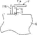
在图9中,附图标记11表示辐射元件(激励元件),其由辐射导体部分11a,短导体部分11b和馈电部分11c组成;12表示接地板;和13表示辐射元件11的馈电部分11c用的馈电点。具有这种结构的倒F型天线,通过使四分之一波长单极天线的辐射元件弯曲,已成功地减小了尺寸。倒F型天线的另一特点是能在辐射元件11a和要连接到馈电点13的馈线(未示)例如同轴线之间获得阻抗匹配。In FIG. 9,
螺旋天线能作为以其可得到紧凑性的另一个例子。图10是螺旋天线的一个示例的平面图。图中,附图标记14表示由绕成螺旋式样的四分之一波长导线构成的辐射元件(激励元件);15表示接地板;和16表示辐射元件14的馈电点。具有这种结构的螺旋天线已知为紧凑的天线,它的方向特性遭受干扰较少,并在VSWR(电压驻波比)特性上占优。A helical antenna can serve as another example of the compactness for which it can be achieved. Fig. 10 is a plan view of an example of a helical antenna. In the drawings,
近来,移动通信设备保持着快速普及和发展势头,小型化已成为移动通信设备日益增长的要求,因此,用在这种设备中的天线,要求紧凑的尺寸和窄小的安装空间。Recently, mobile communication equipment has maintained a rapid popularization and development momentum, and miniaturization has become an increasing requirement for mobile communication equipment. Therefore, antennas used in such equipment require compact size and narrow installation space.
但是,如图9所示的倒F型天线的结构,对进一步小型化趋势是不利的。这是因为倒F型天线要求与四分之一波长相等的可观长度,例如,频率为800MHz时,要求具有长达9cm的长度,因此,若要安装在小尺寸移动通信设备中,就显得太长了。However, the structure of the inverted-F antenna as shown in FIG. 9 is unfavorable for further miniaturization. This is because the inverted-F antenna requires a considerable length equal to a quarter wavelength. For example, when the frequency is 800 MHz, it requires a length of up to 9 cm. Therefore, it is too large to be installed in a small-sized mobile communication device. long.
此外,一般来说,天线的小型化会引起增益降低的问题,还有带宽变窄的问题。在图10所示的螺旋天线中,通过吸持磁能量而使电气体积减小。所以,这种螺旋天线导致带宽明显降低,从而难以获得宽的带宽,即使采用匹配电路。In addition, in general, the miniaturization of the antenna causes a problem of a decrease in gain and a problem of narrowing of the bandwidth. In the helical antenna shown in FIG. 10, the electrical volume is reduced by absorbing magnetic energy. Therefore, such a helical antenna results in a marked decrease in bandwidth, making it difficult to obtain a wide bandwidth even with a matching circuit.
螺旋天线的另一问题是,由于电流流过螺旋导线所制成的辐射元件14而引起相对较大的导体损耗。当使用在日益变小而使用较高频率的移动通信设备中时,这个问题导致天线增益降低。Another problem with helical antennas is the relatively large conductor losses caused by the current flowing through the radiating
发明内容Contents of the invention
从上述常规技术中的问题着眼,实现了出本发明,所以它的目的是提供一种小型的天线装置,它占用很小的安装空间,能实现宽的带宽,并且所受的导体损耗较低。Focusing on the problems in the above-mentioned conventional technologies, the present invention has been achieved, so its object is to provide a small antenna device that occupies a small installation space, can achieve a wide bandwidth, and suffers from low conductor loss .
本发明提供一种天线装置,包括:The present invention provides an antenna device, comprising:
由矩形导体形成的激励元件;和an active element formed from a rectangular conductor; and
接地板,其被安排成接近激励元件的至少一个侧边,它们之间有预定的安全间隔。A ground plate is arranged adjacent to at least one side of the active element with a predetermined safety interval therebetween.
根据本发明的天线装置包括:由矩形导体形成的激励元件,和接地板,其被安排成接近激励元件的至少一个侧边,它们之间有预定的安全间隔。这种结构有如下优点:首先,即使接地板被安排成接近激励元件,增益的降低也能被抑制,因而有可能实现要求安装空间较小的天线装置。其次,通过利用接地板作为辐射元件,辐射电阻能被增加,从而使能够获得宽的带宽。第三,由于激励元件宽度做得比较大,因而有可能减少起因于激励元件中的电阻分量的损耗。最后,通过适当选择激励元件的形状和保证激励元件和接地板之间适当的间隔,有可能提供其导体损耗能成功地降低的天线装置。An antenna device according to the present invention includes: an excitation element formed of a rectangular conductor, and a ground plate arranged close to at least one side of the excitation element with a predetermined safety interval therebetween. This structure has the following advantages. First, even if the ground plate is arranged close to the excitation element, the decrease in gain can be suppressed, so that it is possible to realize an antenna device requiring less installation space. Second, by using the ground plane as a radiation element, radiation resistance can be increased, thereby enabling a wide bandwidth to be obtained. Third, since the width of the driving element is made relatively large, it is possible to reduce the loss due to the resistance component in the driving element. Finally, by properly selecting the shape of the active element and ensuring an appropriate spacing between the active element and the ground plane, it is possible to provide an antenna device whose conductor loss can be successfully reduced.
在本发明中,更可取的是在上述结构中,接地板由基本上为矩形的导体形成,其具有的长度和宽度,是1/5至1/1倍信号波长的范围内。In the present invention, it is preferable that in the above structure, the ground plate is formed of a substantially rectangular conductor having a length and a width in the range of 1/5 to 1/1 times the signal wavelength.
根据本发明,只要接地板由基本上为矩形的导体形成,其具有的长度和宽度是1/5至1/1倍信号波长的范围内,那么流过接地板的电流就有效地用作辐射。因此,在天线中,带宽就比较宽,并且辐射图的构成是使主波束变得更为显著。另外,在这种情况下,流经接地板的电流容易被带入谐振状态。特别是,如果接地板具有的长度和宽度等于1/2倍波长,具体实施本发明的天线装置就能起到边缘馈电偶极子天线的作用,因而表现出宽带的特性。According to the present invention, as long as the ground plane is formed of a substantially rectangular conductor having a length and width in the range of 1/5 to 1/1 times the signal wavelength, the current flowing through the ground plane is effectively used as radiation . Therefore, in the antenna, the bandwidth is wider and the radiation pattern is constructed so that the main beam becomes more prominent. Also, in this case, the current flowing through the ground plate is easily brought into a resonance state. In particular, if the ground plate has a length and a width equal to 1/2 times the wavelength, the antenna device embodying the present invention can function as an edge-fed dipole antenna, thereby exhibiting broadband characteristics.
在本发明中,更可取的是,在上述结构中,激励元件具有的长度是在1/20至1/10倍信号波长的范围内,并且具有的宽度是在1/5至1/1倍信号波长的范围内。In the present invention, preferably, in the above structure, the excitation element has a length in the range of 1/20 to 1/10 times the signal wavelength, and a width in the range of 1/5 to 1/1 times range of signal wavelengths.
根据本发明,只要激励元件具有的长度是在1/20至1/10倍信号波长的范围内,具有的宽度是在1/5至1/1倍信号波长的范围内,就能够抑制导体损耗,而同时保证必要的最小电气长度。因此,能够提供一种能顺利实现小型化且增加辐射效率的天线装置。According to the present invention, as long as the excitation element has a length in the range of 1/20 to 1/10 times the signal wavelength and a width in the range of 1/5 to 1/1 times the signal wavelength, conductor loss can be suppressed , while ensuring the necessary minimum electrical length. Therefore, it is possible to provide an antenna device that can achieve miniaturization smoothly and increase radiation efficiency.
在本发明中,更可取的是,在上述结构中,激励元件和接地板之间的间隔保持在1/200至1/30倍信号波长的范围内。In the present invention, it is preferable that, in the above structure, the interval between the excitation element and the ground plate is maintained within the range of 1/200 to 1/30 times the signal wavelength.
根据本发明,只要激励元件和接地板之间的间隔保持在1/200至1/30倍信号波长的范围内,就能够减少接地板和激励元件中存在的导体损耗,而同时减小安装空间。因此,能够提供一种能顺利实现小型化且增加辐射效率的天线装置。According to the present invention, as long as the distance between the excitation element and the ground plane is maintained within the range of 1/200 to 1/30 times the signal wavelength, the conductor loss existing in the ground plane and the excitation element can be reduced while reducing the installation space . Therefore, it is possible to provide an antenna device that can achieve miniaturization smoothly and increase radiation efficiency.
在本发明中,更可取的是,在上述结构中,激励元件和接地板安排在由介电或磁性体形成的基底的上表面或其内部的同一平面上。In the present invention, preferably, in the above structure, the excitation element and the ground plate are arranged on the same plane on the upper surface of the substrate formed of a dielectric or magnetic body or inside thereof.
根据本发明,只要激励元件和接地板安排在由介电或磁性体形成的基底的上表面或其内部的同一平面上,就不需要将天线装置设计成在垂直于基底的方向上延伸。因此,有可能提供一种较小轮廓的天线装置。According to the present invention, as long as the excitation element and the ground plate are arranged on the same plane on the upper surface of or inside the substrate formed of a dielectric or magnetic body, there is no need to design the antenna device to extend in a direction perpendicular to the substrate. Therefore, it is possible to provide a smaller profile antenna arrangement.
在本发明中,更可取的是,在上述结构中,激励元件和接地板安排在由介电或磁性体形成的基底的上表面或其内部的不同平面上。In the present invention, preferably, in the above structure, the excitation element and the ground plate are arranged on different planes on the upper surface of the substrate formed of a dielectric or magnetic body or inside thereof.
根据本发明,只要激励元件和接地板安排在由介电或磁性体形成的基底的上表面或其内部的不同平面上,就可在激励元件和接地板之间建立一个空隙,如在基底厚度方向所观察到的那样。因此,提供在接地板上的所谓切去区域,能在面积上被减小,从而使得能够实现小型天线装置,并进一步减小安装激励元件所要求的空间。According to the present invention, as long as the excitation element and the ground plate are arranged on different planes on the upper surface or inside of the substrate formed by a dielectric or magnetic body, a gap can be established between the excitation element and the ground plate, such as in the thickness of the substrate direction as observed. Therefore, a so-called cut-out area provided on the ground plate can be reduced in area, thereby enabling realization of a small-sized antenna device and further reducing the space required for mounting the excitation element.
在本发明中,更可取的是,激励元件通过一个匹配电路连接至馈电点。In the present invention, it is preferable that the excitation element is connected to the feeding point through a matching circuit.
在本发明中,更可取的是,接地板由基本上为矩形的导体形成,其具有的长度和宽度小于1/1倍信号波长。In the present invention, it is preferable that the ground plate is formed of a substantially rectangular conductor having a length and width less than 1/1 times the signal wavelength.
在本发明中,更可取的是,接地板有一个与激励元件相对应的切去部分。In the present invention, it is preferable that the ground plate has a cut-out portion corresponding to the excitation element.
根据本发明,提供有一种小型天线装置,它要求较小的安装空间,获得宽的带宽,导致低的导体损耗。According to the present invention, there is provided a compact antenna arrangement which requires less installation space, achieves a wide bandwidth, and results in low conductor losses.
附图说明Description of drawings
本发明的其他和进一步的目的,特点和优点,在下面参考附图进行的详细描绘中,将变得更加明晰,附图中:Other and further objects, features and advantages of the present invention will become more apparent in the following detailed description with reference to the accompanying drawings, in which:
图1是根据本发明的一个实施例的天线装置平面图;Fig. 1 is a plan view of an antenna device according to an embodiment of the present invention;
图2是根据本发明的这个实施例的天线装置的分解透视图;FIG. 2 is an exploded perspective view of the antenna device according to this embodiment of the present invention;
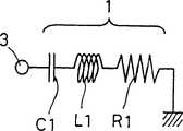
图3是具体实施本发明的天线装置的等效电路图,其中不带匹配电路;Fig. 3 is the equivalent circuit diagram of the antenna device embodying the present invention, wherein there is no matching circuit;
图4是具体实施本发明的天线装置的等效电路图,其中具有匹配电路;Fig. 4 is the equivalent circuit diagram of the antenna device embodying the present invention, wherein has a matching circuit;
图5是根据本发明的另一个实施例的天线装置的分解透视图;5 is an exploded perspective view of an antenna device according to another embodiment of the present invention;
图6是根据本发明的另一个实施例的天线装置平面图;6 is a plan view of an antenna device according to another embodiment of the present invention;
图7是根据本发明的又一个实施例的天线装置的分解透视图;7 is an exploded perspective view of an antenna device according to yet another embodiment of the present invention;
图8是根据本发明的再一个实施例的天线装置平面图;8 is a plan view of an antenna device according to another embodiment of the present invention;
图9是常规倒F型天线示例的平面图;Figure 9 is a plan view of an example of a conventional inverted-F antenna;
图10是常规螺旋天线示例的平面图。Fig. 10 is a plan view of an example of a conventional helical antenna.
具体实施方式Detailed ways
现在,参考附图,对本发明的优选实施例描述如下。Now, referring to the accompanying drawings, preferred embodiments of the present invention are described below.
图1是根据本发明的一个实施例的天线装置平面图。在图1中,附图标记1表示的矩形导体形成的激励元件,2表示接地板,它被安排于接近激励元件的至少一个侧边,这里是它的两个侧边,它们之间有预定的安全间隔。另外,附图标记3表示向激励元件1馈电的馈电点;4表示馈电导体,用来构成将激励元件1电连接至馈电点3的馈电路径;5表示匹配电路,它安装在馈电导体4长度方向的中途,以便位于馈电点3和激励元件1之间。匹配电路5,被提供在所需的基底上由电感匹配和阻抗匹配所要求的电感元件,电容元件等组合而成,旨在补偿激励元件1的电气长度。参考符号W表示激励元件1与接地板2之间的预定的安全间隔。FIG. 1 is a plan view of an antenna device according to an embodiment of the present invention. In Fig. 1,
根据具体实施本发明的天线装置,激励元件1由矩形导体形成,其是用导电材料例如铜箔或银制成的小尺寸的元件。激励元件1具有极短的保持在1/20至1/10倍信号波长的范围的电气长度(如1/20至1/10波长的长度)。安排于接近激励元件至少一个侧边而又具有预定间隔的是接地板2,伴随向激励元件1馈电,在接地板2中感生与信号相应的电流。所述激励元件1和接地板2构成天线。利用这种设计,电流可在接地板2中感生,导致辐射电阻的增加。因此,因此可以实现一种小型宽带天线。According to the antenna device embodying the present invention, the
另外,在具体实施本发明的天线装置中,由于它的结构简单,在信号功率流经激励元件1和接地板2时,产生的导体损失表现为最小,因此,由导体损失引起的天线增益的减退,可保持为最小。In addition, in the antenna device that implements the present invention, due to its simple structure, when the signal power flows through the
本发明的一个实施例的天线装置,以图2中的分解透视图表示。在图2中,与图1中起相同的作用或相应的作用的元件,将以相同的参考号符识别,因此,附图标记1表示激励元件;2表示接地板;3表示馈电点;4表示馈电导体;和5表示匹配电路。另外,6表示由介电或磁性体制成的基底。例如,基底6由介电材料构成,例如玻璃纤维环氧树脂、PTFE(聚四氟乙烯)、或氧化铝陶瓷,或者磁性材料例如Ni-Zn铁氧体。An antenna device according to an embodiment of the present invention is shown in an exploded perspective view in FIG. 2 . In FIG. 2, elements that play the same role or have corresponding roles as those in FIG. 1 will be identified with the same reference symbols, therefore,
在这个实施例中,基底6的上表面上安排由矩形导体形成的激励元件1,馈电点3,馈电导体4和匹配电路5。在基底6的下表面安排接地板2,其具有切下的角落,以便将其安排在接近于激励元件1的两个侧边,在它们之间有预定的安全间隔。就是说,激励元件1和接地板2安排在基底6的不同表面上。In this embodiment, the
更具体地说,在根据本实施例的结构中,例如使用玻璃环氧树脂基底(具有大小为40mm×30mm,厚度为0.6mm的矩形形状,相对介电常数为4.8)作基底6。使用9mm长×3mm宽的矩形导体板作激励元件1。激励元件1安排在基底6的上表面的角落部分。安排在基底6下表面的接地板2,则以导体板制成,其具有11mm长×4mm宽的矩形切去部分,以便面向处于基底6的角落的激励元件1两个侧边。这样,有可能实现工作在近似2.4GHz频率的天线装置。More specifically, in the structure according to the present embodiment, for example, a glass epoxy resin substrate (having a rectangular shape with a size of 40 mm×30 mm, a thickness of 0.6 mm, and a relative dielectric constant of 4.8) is used as the substrate 6 . A rectangular conductor plate with a length of 9 mm x a width of 3 mm was used as the
下面,将参考图3和4所示的等效电路图,描述具体实施本发明的天线装置中所采用的匹配电路5的作用。Next, the action of the matching circuit 5 employed in the antenna device embodying the present invention will be described with reference to the equivalent circuit diagrams shown in FIGS. 3 and 4. FIG.
图3示出有关激励元件1的等效电路图,如所看到的,这里未提供匹配电路5。在具体实施本发明的天线装置中,由于激励元件1长度非常小,例如1/20至1/10波长的长度,如果没有匹配电路5,激励元件1则呈现电容特性。通过在馈电点3向激励元件1馈电,在安排于附近的接地板2中感生电流,导致辐射电阻的产生。在这种情况下,如图3所示,激励元件1的等效电路由连接电容C1,电感L1和辐射电阻R1相互串联组成。FIG. 3 shows an equivalent circuit diagram for the
于是,上述特定实例在近似2.4GHz频率下计算,给出C1为1.2PF,L1为1.2nH,和R1为3.5Ω。Thus, the above specific example calculated at a frequency of approximately 2.4GHz gives C1 of 1.2PF, L1 of 1.2nH, and R1 of 3.5Ω.
图4示出一个实例的等效电路图,其中附加有匹配电路5。在用5Ω馈电线作馈电线4的情况下,匹配电路5用于完成激励元件1与馈电线4之间的匹配。如图4所示,匹配电路5由电感L2和电容C2组成。电感L2与馈电线4串联。电容C2连接在馈电线4与地之间。在这个实例中,将电感L2调节为2nH,电容C2调节为4.5PF,可达到匹配。当电压驻波比(VSWR)为2(相对带宽:4%)时,给出作为匹配结果所获得的阻抗带宽为100MHz,当电压驻波比为了(相对带宽:8%)时,给出带宽为200MHz。因此,能够获得宽带特性。FIG. 4 shows an equivalent circuit diagram of an example in which a matching circuit 5 is added. In the case of using a 5Ω feeder as the feeder 4 , the matching circuit 5 is used to complete the matching between the
在具体实施本发明的天线装置中,当接地板2尺寸减少到某个程度以下时,R1急剧地减小,导致阻抗带宽变得较窄。与这个趋势有关,下面所列举的是关于接地板2的尺寸与阻抗带宽之间的对应数据,作为对上述实例检验。要注意,从整体上看,接地板2具有矩形形状,严格地说,基本上是矩形形状,因为切去了与激励元件1相应的一部分。In the antenna device embodying the present invention, when the size of the ground plate 2 is reduced below a certain level, R1 decreases sharply, resulting in a narrower impedance bandwidth. In connection with this tendency, enumerated below are data on the correspondence between the size of the ground plate 2 and the impedance bandwidth, as a check for the above-mentioned example. It is to be noted that, viewed as a whole, the ground plate 2 has a rectangular shape, strictly speaking, substantially a rectangular shape because a portion corresponding to the
接地板尺寸 阻抗带宽Ground Plane Dimensions Impedance Bandwidth
20mm×15mm 40MHz20mm×15mm 40MHz
40mm×30mm 100MHz40mm×30mm 100MHz
50mm×50mm 100MHz50mm×50mm 100MHz
从数据将可了解,由基本上是矩形的导体制成的接地板2尺寸越大,阻抗带宽就越宽。如果接地板2给出的尺寸,等于或大于1/5波长(信号波长的1/5倍)(在大约2.4GHz频率上,约大于25mm),阻抗带宽就补被饱和。这里应该注意,如果接地板2具有尺寸等于或大于1波长(1/1倍信号波长)(在大约2.4GHz频率上约大于125mm),则在信号辐射图型中出现畸变的趋势。It will be understood from the data that the larger the size of the ground plate 2 made of substantially rectangular conductors, the wider the impedance bandwidth. If the size given by the ground plane 2 is equal to or greater than 1/5 wavelength (1/5 times the signal wavelength) (about 25mm greater than about 2.4GHz frequency), the impedance bandwidth is saturated. It should be noted here that if the ground plate 2 has a size equal to or larger than 1 wavelength (1/1 times the signal wavelength) (approximately larger than 125 mm at a frequency of approximately 2.4 GHz), distortion tends to occur in the signal radiation pattern.
在具体实施本发明的天线装置中,激励元件1,接地板2的导体切去区域,和激励元件1与接地板2之间的间隔W全是获得满意的天线特性的关键元件。具体实施本发明的天线装置,是以与前面所述具体实例基本相同的方式构成的,不同的是,在玻璃环氧树脂基底6的上表面角落,安排有由11mm长×5mm宽的矩形导体板制成的激励元件1,以及,在基底6的下表面角落,接近地安排有接地板2,其具有13mm长×6mm宽的导体切去部分,以便面向激励元件1的两个侧边(在激励元件1和接地板2之间两边的安全间隔W两者,都设置为1mm)。在这种结构中,当电压驻波比为2(相对带宽:10%)时,给出阻抗带宽为260MHz。因此,能够获得优良的宽带宽特性。In the antenna device embodying the present invention, the
从等效电路研究的结果可以清楚,通过提高激励元件1的电容C1和辐射电阻R1,能实现宽带的天线装置。It is clear from the results of equivalent circuit studies that a broadband antenna device can be realized by increasing the capacitance C1 and the radiation resistance R1 of the
在具体实施本发明的天线装置中,激励元件1与接地板2之间的间隔W,从获得满意的天线特性的观点来说,是特别重要的。如果间隔W做得很小,在激励元件1中,电容C1会提高,辐射电阻R1则降低。因此,对包括用于匹配电路5电路元件的芯片元件的数值等的检验,进行了广泛的研究。最后,为了获得满意的天线特性,激励元件1与接地板2之间的间隔W应当希望保持在1/200至1/30倍信号波长的范围内(1/200至1/30波长的长度,例如,对于大约2.4GHz的信号,约为0.5至2mm)。如果间隔W小于1/200倍信号波长,则辐射效率下降。相反,如果间隔W大于1/30倍信号波长,激励元件1的外表在结构上就变得不适当地大,这导致实现天线装置小型化的困难,并且不可能提供明显的安装优点。In the antenna device embodying the present invention, the interval W between the
另外,根据对具体实施本发明的,在矩形导体形成的激励元件1的长度和宽度之间关系的研究结果,已经发现,希望保持激励元件1的长度在1/20至1/10倍信号波长的范围内(1/20至1/10波长的长度)。如果长度小于1/20倍信号波长,则频率有因插入为补偿电气长度的匹配电路5的电感变化而引起很大变化的倾向,并且电感的损耗也变成有问题。相反,如果长度大于1/10倍波长,激励元件1的外表在结构上变得不适当地大,这导致实现天线装置小型化的困难,并且不可能提供明显的安装优点。另一方面,已经发现,激励元件1的宽度越小,它的辐射电阻R1和电容C1倾向于越小,因此,阻抗带宽就大大地变窄,导致制作的天线不实用。根据这一研究结果。已经发现,宽度希望保持在1/5至1/1倍长度范围内,以便获得最满意的辐射特性。如果宽度小于1/5倍长度,导体损耗就变成不适当地大。相反,如果宽度大于1/1倍长度,则难以实现对激励元件1进行有效的馈电。In addition, according to the results of research on the relationship between the length and width of the
在具体实施本发明的天线装置中,从馈电点3给匹配电路5向激励元件1馈电的馈电位置,是如图2中所示的实施例所描述的那样。另一方式,如类似于图2的图5分解透视图所示的实施例中所见,馈电位置可设置在激励元件1的电磁中性点附近。在这种情况下,与图2所示的实施例不同,不改变电路常数就不能利用匹配电路5。In the antenna device embodying the present invention, the feeding position from the
其次,根据本发明另一实施例的天线装置,如在类似于图1的图6中的平面所示。在图6中,起着与图1中相同或相应作用的元件,以相同的参考符号识别,因此,附图标记1表示激励元件;Z表示接地板;3表示馈电点;4表示馈电导体;和5表示匹配电路。在这个实施例中,玻璃环氧树脂基底(未示)具有0.6mm的厚度,4.8的相对介电常数;在其上表面安排有由9mm长×3mm宽的矩形导体形成的激励元件1。在基底的上表面接近激励元件1处,安排有接地板2。接地板2在其一侧边缘有一个11mm长×4mm宽的矩形切去部分,以便包围激励元件1的三个侧边。在这种结构中,与图1至3所示的实施例相比,难以在接地板2感生电流,因此,激励元件1的辐射电阻R1减小。这引起阻抗带宽变窄。在这个实例中,当电压驻波比为2时,给出80MHz的阻抗带宽。Next, an antenna device according to another embodiment of the present invention is shown in a plane in FIG. 6 similar to FIG. 1 . In Fig. 6, elements that play the same or corresponding roles as those in Fig. 1 are identified with the same reference symbols, therefore,
在具体实施本发明的天线装置中,与图1和2所示的实施例不同,如类似于图2的图7中的分解透视所示,通过在上表面或由介质或磁性体制成的基底7的内部,形成由矩形导体组成的激励元件1,能够使激励元件1被选择,并容易按所希望的频率替换。因此,能改善天线装置的易安装性。In the antenna device embodying the present invention, different from the embodiments shown in FIGS. 1 and 2, as shown in an exploded perspective similar to FIG. 7 in FIG. Inside 7, an
根据本发明的又一实施例的天线装置,如类似于图6的图8的平面图所示。从图8可以看出,接地板2可这样来构成,即它被安排成接近激励元件1的四个侧边,它们之间有预定的安全距离,从而包围激励元件1的周围。在采用这种结构的天线装置中,带宽较窄,但能实现高度的安装灵活性。An antenna device according to yet another embodiment of the present invention is shown in a plan view of FIG. 8 similar to FIG. 6 . As can be seen from FIG. 8 , the ground plate 2 can be constructed in such a way that it is arranged close to the four sides of the
应当了解,本发明的应用不局限前述具体实施例,在本发明的精神和范围内,可能做许多修改和变化。例如,激励元件1可以倒角弄圆。It should be understood that the application of the present invention is not limited to the foregoing specific embodiments, and many modifications and variations are possible within the spirit and scope of the present invention. For example, the
在不偏离本发明的精神或基本特性的情况下,本发明可以用其他具体形式来实施。因此,现有的实施例要在图示的所有方面加以考虑,并且不受限制,本发明的范围是由所附权利要求所限定的,而不是由上面的描述所指示的,而且在权利要求范围内的各种等效内容或全部变动都包含在本发明的范围内。The present invention may be embodied in other specific forms without departing from the spirit or essential characteristics of the inventions. Accordingly, the present embodiments are to be considered in all respects illustrated and not to be limited, the scope of the invention being defined by the appended claims rather than as indicated by the foregoing description, and by the appended claims Various equivalent contents or all modifications within the scope are included in the scope of the present invention.
Claims (9)
Applications Claiming Priority (2)
| Application Number | Priority Date | Filing Date | Title |
|---|---|---|---|
| JP2001287711 | 2001-09-20 | ||
| JP2001287711AJP2003101332A (en) | 2001-09-20 | 2001-09-20 | Antenna device |
Related Child Applications (1)
| Application Number | Title | Priority Date | Filing Date |
|---|---|---|---|
| CNB2006100050063ADivisionCN100566021C (en) | 2001-09-20 | 2002-09-19 | Antenna assembly |
Publications (2)
| Publication Number | Publication Date |
|---|---|
| CN1405924Atrue CN1405924A (en) | 2003-03-26 |
| CN1274060C CN1274060C (en) | 2006-09-06 |
Family
ID=19110477
Family Applications (2)
| Application Number | Title | Priority Date | Filing Date |
|---|---|---|---|
| CNB021424543AExpired - Fee RelatedCN1274060C (en) | 2001-09-20 | 2002-09-19 | Antenna device |
| CNB2006100050063AExpired - Fee RelatedCN100566021C (en) | 2001-09-20 | 2002-09-19 | Antenna assembly |
Family Applications After (1)
| Application Number | Title | Priority Date | Filing Date |
|---|---|---|---|
| CNB2006100050063AExpired - Fee RelatedCN100566021C (en) | 2001-09-20 | 2002-09-19 | Antenna assembly |
Country Status (4)
| Country | Link |
|---|---|
| US (1) | US6970135B2 (en) |
| JP (1) | JP2003101332A (en) |
| KR (1) | KR20030025789A (en) |
| CN (2) | CN1274060C (en) |
Cited By (4)
| Publication number | Priority date | Publication date | Assignee | Title |
|---|---|---|---|---|
| CN100452533C (en)* | 2003-06-24 | 2009-01-14 | 京瓷株式会社 | Antenna, antenna module and radio communication apparatus provided with the same |
| CN102195122A (en)* | 2010-03-12 | 2011-09-21 | 宏碁股份有限公司 | Thin mobile communication device |
| CN104103889A (en)* | 2013-04-02 | 2014-10-15 | 智易科技股份有限公司 | Antenna structure and manufacturing method thereof |
| CN107210528A (en)* | 2015-02-11 | 2017-09-26 | 华为技术有限公司 | A kind of multifrequency antenna and terminal device |
Families Citing this family (32)
| Publication number | Priority date | Publication date | Assignee | Title |
|---|---|---|---|---|
| WO2005004282A1 (en)* | 2003-07-04 | 2005-01-13 | Mitsubishi Denki Kabushiki Kaisha | Antenna element and mobile telephone device |
| JP2005303721A (en) | 2004-04-13 | 2005-10-27 | Sharp Corp | Antenna and portable radio using the same |
| US7339537B2 (en)* | 2004-10-28 | 2008-03-04 | Alliant Techsystems Inc. | Capacitive drive antenna and an air vehicle so equipped |
| JP2006186969A (en)* | 2004-12-01 | 2006-07-13 | Omron Corp | Antenna |
| US7417591B2 (en)* | 2005-02-17 | 2008-08-26 | Matsushita Electric Industrial Co., Ltd. | Antenna apparatus and portable wireless device using the same |
| JP2006314005A (en)* | 2005-05-09 | 2006-11-16 | Nippon Antenna Co Ltd | Built-in antenna |
| JP4368838B2 (en)* | 2005-09-27 | 2009-11-18 | 京セラ株式会社 | Wireless communication terminal |
| TWI342639B (en)* | 2006-07-28 | 2011-05-21 | Lite On Technology Corp | A compact dtv receiving antenna |
| CN101114727B (en)* | 2006-07-28 | 2011-05-18 | 光宝科技股份有限公司 | A Miniaturized Digital TV Receiving Antenna |
| US7764236B2 (en)* | 2007-01-04 | 2010-07-27 | Apple Inc. | Broadband antenna for handheld devices |
| EP2140517A1 (en)* | 2007-03-30 | 2010-01-06 | Fractus, S.A. | Wireless device including a multiband antenna system |
| TWI334241B (en)* | 2007-05-10 | 2010-12-01 | Asustek Comp Inc | Antenna |
| US8203492B2 (en) | 2008-08-04 | 2012-06-19 | Fractus, S.A. | Antennaless wireless device |
| US8237615B2 (en) | 2008-08-04 | 2012-08-07 | Fractus, S.A. | Antennaless wireless device capable of operation in multiple frequency regions |
| JP2010154077A (en)* | 2008-12-24 | 2010-07-08 | Fujitsu Component Ltd | Antenna device |
| CN101540432B (en)* | 2009-05-08 | 2012-07-04 | 华为终端有限公司 | Antenna design method and data card veneer of wireless terminal |
| WO2011004656A1 (en)* | 2009-07-09 | 2011-01-13 | 株式会社村田製作所 | Antenna |
| JP2011061758A (en) | 2009-08-10 | 2011-03-24 | Fujitsu Component Ltd | Antenna device |
| JP5471322B2 (en)* | 2009-11-09 | 2014-04-16 | 富士通株式会社 | Antenna device |
| US8368602B2 (en) | 2010-06-03 | 2013-02-05 | Apple Inc. | Parallel-fed equal current density dipole antenna |
| WO2012017013A1 (en) | 2010-08-03 | 2012-02-09 | Fractus, S.A. | Wireless device capable of multiband mimo operation |
| US9577325B2 (en) | 2012-06-20 | 2017-02-21 | Fractus Antennas, S.L. | Compact radiating array for wireless handheld or portable devices |
| US9379443B2 (en) | 2012-07-16 | 2016-06-28 | Fractus Antennas, S.L. | Concentrated wireless device providing operability in multiple frequency regions |
| US9331389B2 (en) | 2012-07-16 | 2016-05-03 | Fractus Antennas, S.L. | Wireless handheld devices, radiation systems and manufacturing methods |
| TWI557988B (en)* | 2013-01-03 | 2016-11-11 | 宏碁股份有限公司 | Communication device |
| CN103928755B (en)* | 2013-01-11 | 2016-09-28 | 宏碁股份有限公司 | communication device |
| TWI511374B (en)* | 2013-02-04 | 2015-12-01 | Acer Inc | Communication device with tunable ground plane antenna element |
| CN103996897A (en)* | 2013-02-20 | 2014-08-20 | 宏碁股份有限公司 | Communication device with adjustable ground plane antenna element |
| US10062973B2 (en) | 2013-06-20 | 2018-08-28 | Fractus Antennas, S.L. | Scattered virtual antenna technology for wireless devices |
| ES2973383T3 (en)* | 2014-07-24 | 2024-06-19 | Ignion S L | Slim radiation systems for electronic devices |
| US10224631B2 (en) | 2015-03-27 | 2019-03-05 | Fractus Antennas, S.L. | Wireless device using an array of ground plane boosters for multiband operation |
| CN112886242A (en)* | 2021-01-12 | 2021-06-01 | 珠海格力电器股份有限公司 | Matching circuit, on-board antenna, verification method and verification device for on-board antenna |
Family Cites Families (8)
| Publication number | Priority date | Publication date | Assignee | Title |
|---|---|---|---|---|
| US4063246A (en)* | 1976-06-01 | 1977-12-13 | Transco Products, Inc. | Coplanar stripline antenna |
| GB2213996A (en)* | 1987-12-22 | 1989-08-23 | Philips Electronic Associated | Coplanar patch antenna |
| JPH05226919A (en) | 1991-06-26 | 1993-09-03 | Libbery Owens Ford Co | Antenna for window embedded type car |
| JPH1127025A (en) | 1997-07-03 | 1999-01-29 | Murata Mfg Co Ltd | Antenna device |
| JP3738577B2 (en) | 1998-02-13 | 2006-01-25 | 株式会社村田製作所 | ANTENNA DEVICE AND MOBILE COMMUNICATION DEVICE |
| US20060027494A1 (en)* | 1999-01-23 | 2006-02-09 | Aaf-Mcquay, Inc., A Kentucky Corporation | Oil treated filter media |
| JP2001168625A (en) | 1999-12-08 | 2001-06-22 | Toshiba Corp | Wireless communication device and electronic equipment |
| JP2001358517A (en)* | 2000-06-15 | 2001-12-26 | Murata Mfg Co Ltd | Antenna device and radio equipment using the same |
- 2001
- 2001-09-20JPJP2001287711Apatent/JP2003101332A/enactivePending
- 2002
- 2002-06-14KRKR1020020033188Apatent/KR20030025789A/ennot_activeWithdrawn
- 2002-09-18USUS10/246,389patent/US6970135B2/ennot_activeExpired - Fee Related
- 2002-09-19CNCNB021424543Apatent/CN1274060C/ennot_activeExpired - Fee Related
- 2002-09-19CNCNB2006100050063Apatent/CN100566021C/ennot_activeExpired - Fee Related
Cited By (6)
| Publication number | Priority date | Publication date | Assignee | Title |
|---|---|---|---|---|
| CN100452533C (en)* | 2003-06-24 | 2009-01-14 | 京瓷株式会社 | Antenna, antenna module and radio communication apparatus provided with the same |
| CN102195122A (en)* | 2010-03-12 | 2011-09-21 | 宏碁股份有限公司 | Thin mobile communication device |
| CN102195122B (en)* | 2010-03-12 | 2014-01-22 | 宏碁股份有限公司 | Thin mobile communication device |
| CN104103889A (en)* | 2013-04-02 | 2014-10-15 | 智易科技股份有限公司 | Antenna structure and manufacturing method thereof |
| CN104103889B (en)* | 2013-04-02 | 2017-09-22 | 智易科技股份有限公司 | Antenna structure and manufacturing method thereof |
| CN107210528A (en)* | 2015-02-11 | 2017-09-26 | 华为技术有限公司 | A kind of multifrequency antenna and terminal device |
Also Published As
| Publication number | Publication date |
|---|---|
| JP2003101332A (en) | 2003-04-04 |
| CN100566021C (en) | 2009-12-02 |
| US6970135B2 (en) | 2005-11-29 |
| KR20030025789A (en) | 2003-03-29 |
| US20030063036A1 (en) | 2003-04-03 |
| CN1274060C (en) | 2006-09-06 |
| CN1819336A (en) | 2006-08-16 |
Similar Documents
| Publication | Publication Date | Title |
|---|---|---|
| CN1405924A (en) | Antenna device | |
| US7102572B2 (en) | Antenna and wireless communication card | |
| CN1108643C (en) | Small antenna for portable radio equipment | |
| EP1569299B1 (en) | Antenna, dielectric substrate for antenna, radio communication card | |
| US6639559B2 (en) | Antenna element | |
| JP4305282B2 (en) | Antenna device | |
| JP2003163528A (en) | Printed circuit board, smd antenna, and communication equipment | |
| CN1259775A (en) | Plane and double frequency aerial, radio frequency device using same | |
| CN100499262C (en) | Radio communication terminal | |
| CN1993860A (en) | Chip Antenna | |
| JP2007089234A (en) | antenna | |
| JP4297164B2 (en) | Antenna structure and wireless communication device including the same | |
| CN1484876A (en) | Antenna device | |
| CN1375890A (en) | Band-width-widen antenna for mobile apparatus | |
| US7071877B2 (en) | Antenna and dielectric substrate for antenna | |
| JP2012142793A (en) | Antenna device | |
| KR20030028402A (en) | Miniaturized directoral antenna | |
| US20030142019A1 (en) | Antenna with substrate and conductor track structure | |
| JP2005312062A (en) | Small antenna | |
| US8274435B2 (en) | Antenna apparatus | |
| CN114094327B (en) | Antenna structure and terminal | |
| HK1049074A1 (en) | Portable radio apparatus and antenna for the same | |
| CN116031637A (en) | 5G antenna and terminal | |
| JP4329579B2 (en) | Antenna device | |
| CN101378150A (en) | Antenna module |
Legal Events
| Date | Code | Title | Description |
|---|---|---|---|
| C06 | Publication | ||
| PB01 | Publication | ||
| C10 | Entry into substantive examination | ||
| SE01 | Entry into force of request for substantive examination | ||
| C10 | Entry into substantive examination | ||
| SE01 | Entry into force of request for substantive examination | ||
| C14 | Grant of patent or utility model | ||
| GR01 | Patent grant | ||
| C19 | Lapse of patent right due to non-payment of the annual fee | ||
| CF01 | Termination of patent right due to non-payment of annual fee |