CN1368787A - LLC series resonant DC/DC converter - Google Patents
LLC series resonant DC/DC converterDownload PDFInfo
- Publication number
- CN1368787A CN1368787ACN01139445ACN01139445ACN1368787ACN 1368787 ACN1368787 ACN 1368787ACN 01139445 ACN01139445 ACN 01139445ACN 01139445 ACN01139445 ACN 01139445ACN 1368787 ACN1368787 ACN 1368787A
- Authority
- CN
- China
- Prior art keywords
- converter
- series
- frequency
- resonance
- transformer
- Prior art date
- Legal status (The legal status is an assumption and is not a legal conclusion. Google has not performed a legal analysis and makes no representation as to the accuracy of the status listed.)
- Granted
Links
Images


Classifications
- H—ELECTRICITY
- H02—GENERATION; CONVERSION OR DISTRIBUTION OF ELECTRIC POWER
- H02M—APPARATUS FOR CONVERSION BETWEEN AC AND AC, BETWEEN AC AND DC, OR BETWEEN DC AND DC, AND FOR USE WITH MAINS OR SIMILAR POWER SUPPLY SYSTEMS; CONVERSION OF DC OR AC INPUT POWER INTO SURGE OUTPUT POWER; CONTROL OR REGULATION THEREOF
- H02M3/00—Conversion of DC power input into DC power output
- H02M3/22—Conversion of DC power input into DC power output with intermediate conversion into AC
- H02M3/24—Conversion of DC power input into DC power output with intermediate conversion into AC by static converters
- H02M3/28—Conversion of DC power input into DC power output with intermediate conversion into AC by static converters using discharge tubes with control electrode or semiconductor devices with control electrode to produce the intermediate AC
- H02M3/325—Conversion of DC power input into DC power output with intermediate conversion into AC by static converters using discharge tubes with control electrode or semiconductor devices with control electrode to produce the intermediate AC using devices of a triode or a transistor type requiring continuous application of a control signal
- H02M3/335—Conversion of DC power input into DC power output with intermediate conversion into AC by static converters using discharge tubes with control electrode or semiconductor devices with control electrode to produce the intermediate AC using devices of a triode or a transistor type requiring continuous application of a control signal using semiconductor devices only
- H02M3/338—Conversion of DC power input into DC power output with intermediate conversion into AC by static converters using discharge tubes with control electrode or semiconductor devices with control electrode to produce the intermediate AC using devices of a triode or a transistor type requiring continuous application of a control signal using semiconductor devices only in a self-oscillating arrangement
- H02M3/3382—Conversion of DC power input into DC power output with intermediate conversion into AC by static converters using discharge tubes with control electrode or semiconductor devices with control electrode to produce the intermediate AC using devices of a triode or a transistor type requiring continuous application of a control signal using semiconductor devices only in a self-oscillating arrangement in a push-pull circuit arrangement
- H—ELECTRICITY
- H02—GENERATION; CONVERSION OR DISTRIBUTION OF ELECTRIC POWER
- H02M—APPARATUS FOR CONVERSION BETWEEN AC AND AC, BETWEEN AC AND DC, OR BETWEEN DC AND DC, AND FOR USE WITH MAINS OR SIMILAR POWER SUPPLY SYSTEMS; CONVERSION OF DC OR AC INPUT POWER INTO SURGE OUTPUT POWER; CONTROL OR REGULATION THEREOF
- H02M3/00—Conversion of DC power input into DC power output
- H02M3/01—Resonant DC/DC converters
- H—ELECTRICITY
- H02—GENERATION; CONVERSION OR DISTRIBUTION OF ELECTRIC POWER
- H02M—APPARATUS FOR CONVERSION BETWEEN AC AND AC, BETWEEN AC AND DC, OR BETWEEN DC AND DC, AND FOR USE WITH MAINS OR SIMILAR POWER SUPPLY SYSTEMS; CONVERSION OF DC OR AC INPUT POWER INTO SURGE OUTPUT POWER; CONTROL OR REGULATION THEREOF
- H02M3/00—Conversion of DC power input into DC power output
- H02M3/22—Conversion of DC power input into DC power output with intermediate conversion into AC
- H02M3/24—Conversion of DC power input into DC power output with intermediate conversion into AC by static converters
- H02M3/28—Conversion of DC power input into DC power output with intermediate conversion into AC by static converters using discharge tubes with control electrode or semiconductor devices with control electrode to produce the intermediate AC
- H02M3/325—Conversion of DC power input into DC power output with intermediate conversion into AC by static converters using discharge tubes with control electrode or semiconductor devices with control electrode to produce the intermediate AC using devices of a triode or a transistor type requiring continuous application of a control signal
- H02M3/335—Conversion of DC power input into DC power output with intermediate conversion into AC by static converters using discharge tubes with control electrode or semiconductor devices with control electrode to produce the intermediate AC using devices of a triode or a transistor type requiring continuous application of a control signal using semiconductor devices only
- H02M3/33569—Conversion of DC power input into DC power output with intermediate conversion into AC by static converters using discharge tubes with control electrode or semiconductor devices with control electrode to produce the intermediate AC using devices of a triode or a transistor type requiring continuous application of a control signal using semiconductor devices only having several active switching elements
- H02M3/33571—Half-bridge at primary side of an isolation transformer
- H—ELECTRICITY
- H02—GENERATION; CONVERSION OR DISTRIBUTION OF ELECTRIC POWER
- H02M—APPARATUS FOR CONVERSION BETWEEN AC AND AC, BETWEEN AC AND DC, OR BETWEEN DC AND DC, AND FOR USE WITH MAINS OR SIMILAR POWER SUPPLY SYSTEMS; CONVERSION OF DC OR AC INPUT POWER INTO SURGE OUTPUT POWER; CONTROL OR REGULATION THEREOF
- H02M3/00—Conversion of DC power input into DC power output
- H02M3/22—Conversion of DC power input into DC power output with intermediate conversion into AC
- H02M3/24—Conversion of DC power input into DC power output with intermediate conversion into AC by static converters
- H02M3/28—Conversion of DC power input into DC power output with intermediate conversion into AC by static converters using discharge tubes with control electrode or semiconductor devices with control electrode to produce the intermediate AC
- H02M3/325—Conversion of DC power input into DC power output with intermediate conversion into AC by static converters using discharge tubes with control electrode or semiconductor devices with control electrode to produce the intermediate AC using devices of a triode or a transistor type requiring continuous application of a control signal
- H02M3/335—Conversion of DC power input into DC power output with intermediate conversion into AC by static converters using discharge tubes with control electrode or semiconductor devices with control electrode to produce the intermediate AC using devices of a triode or a transistor type requiring continuous application of a control signal using semiconductor devices only
- H02M3/33569—Conversion of DC power input into DC power output with intermediate conversion into AC by static converters using discharge tubes with control electrode or semiconductor devices with control electrode to produce the intermediate AC using devices of a triode or a transistor type requiring continuous application of a control signal using semiconductor devices only having several active switching elements
- H02M3/33573—Full-bridge at primary side of an isolation transformer
- Y—GENERAL TAGGING OF NEW TECHNOLOGICAL DEVELOPMENTS; GENERAL TAGGING OF CROSS-SECTIONAL TECHNOLOGIES SPANNING OVER SEVERAL SECTIONS OF THE IPC; TECHNICAL SUBJECTS COVERED BY FORMER USPC CROSS-REFERENCE ART COLLECTIONS [XRACs] AND DIGESTS
- Y02—TECHNOLOGIES OR APPLICATIONS FOR MITIGATION OR ADAPTATION AGAINST CLIMATE CHANGE
- Y02B—CLIMATE CHANGE MITIGATION TECHNOLOGIES RELATED TO BUILDINGS, e.g. HOUSING, HOUSE APPLIANCES OR RELATED END-USER APPLICATIONS
- Y02B70/00—Technologies for an efficient end-user side electric power management and consumption
- Y02B70/10—Technologies improving the efficiency by using switched-mode power supplies [SMPS], i.e. efficient power electronics conversion e.g. power factor correction or reduction of losses in power supplies or efficient standby modes
Landscapes
- Engineering & Computer Science (AREA)
- Power Engineering (AREA)
- Dc-Dc Converters (AREA)
Abstract
Description
Technical field
Relate generally to of the present invention comprises the power system of DC/DC conversion work.More particularly say, the present invention relates to a kind of circuit design of improvement and the soft switch performance that structure reaches better power conversion efficiency, more roomy working range and improvement.
Background technology
The design of the DC/DC converter of known technology and manufacturing have the limitation of low-power conversion efficiency and narrow working range.In particular, in known pulse bandwidth modulation (PWM) transducer, hold time in order to keep output voltage and to reach required under the environment that descends at an input voltage, must compromise to some extent to be issued to the requirement of holding time with regard to duty ratio and other running parameters in a low input condition.Sacrifice power conversion efficiency in the hope of carrying out operate as normal with the input voltage in its normal range (NR).This kind can't can cause power wastage with the DC/DC converter design of selecting the most suitable one normal input voltage range with the circuit design optimization.In addition, as hereinafter further specifying, known controlled resonant converter has narrower input and output voltage range equally, often limits the conversion efficiency of DC/DC converter and use elasticity in practical design.
Known have two kinds of resonate converter, that is resonance series converter and parallel resonance converter.When carrying out, can use an inductance capacitance (LC) resonance circuit to create the lossless condition that is switched on or switched off of semiconductor switch with a full-bridge or half-bridge structure.Fig. 1 shows a resonance series converter with the half-bridge structure implementation, and wherein load and resonance circuit are connected in series.Relatively, Fig. 2 shows a parallel resonance converter with the half-bridge structure implementation, and wherein load and resonating capacitor are arranged in parallel.Generally speaking, when switching frequency was higher than resonance frequency, switch was connected in zero voltage condition, connected switching loss thereby eliminate.In order to regulate output voltage, resonance series converter and parallel resonance converter applications one variable power switch control method for frequency.With regard to a string converter that shakes of allying the communists, major defect is that it needs big frequency range can't obtain well-tuned under no-load condition with output and this output of regulating a roomy loading range.With regard to resonance circuit and load is the case that is connected in parallel, and the converter that shakes of allying the communists in the lump can be regulated output voltage under no-load condition.Yet circulation energy obviously improves.Therefore, power conversion efficiency reduces with load and reduces fast.Again, the two performance of resonance series converter and parallel resonance converter all is subjected to the restriction of the narrower scope of input voltage.
Fig. 3 shows the circuit diagram of LCC resonate converter.LCC resonate converter system adds a string capacitor C that shakes that allies the communists by the parallel resonance convertersObtain.With respect to the parallel resonance converter, the circulation energy of LCC resonate converter reduces and the voltage-regulation performance boost.Yet the LCC resonate converter still is subject to the narrower scope of input voltage.
Therefore, need a kind of resonate converter of improvement to add wide input voltage range and improve conversion efficiency to solve an above-mentioned difficult problem.In particular, need a kind of new circuit framework, it is wanted to keep soft switching characteristic and allows not to be subject to based on the circuit design optimization of normal running conditions the requirement of holding time between the input voltage decrement phase simultaneously.
Summary of the invention
Therefore purpose of the present invention keeps soft switching characteristic simultaneously and allows for a normal running conditions with the circuit design optimization to improve conversion efficiency for the DC/DC transducer configuration that proposes a kind of novelty and design thereof and manufacture method.Therefore the novel DC/DC converter of this improvement allows and is familiar with the difficult problem that present technique field person can overcome known skill.
In particular, purpose of the present invention makes output voltage can by the mode of the switch periods of adjustment a pair of input switch control for a DC/DC converter provides a LLC resonance network to have the double characteristic resonance frequency for proposing a kind of structure and method.The scope of input and output voltage can be that the basis is more flexiblely adjusted and circuit design can be basic optimization with a normal running conditions expediently with these work and control characteristic.
Speak briefly, in a preferred embodiment, the present invention discloses a kind of DC/DC converter.This DC/DC converter comprises a squarer and is used for producing a series of output voltages with a square-wave waveform.This DC/DC converter also comprises a resonance loop and is connected in this squarer, and this resonance circuit comprises that a series connection capacitor is connected in a series connection inductor and an inductor in parallel.This DC/DC converter also comprise a transformer once side be serially connected with this series reactor and be connected to this shunt inductance device.This transformer also comprise secondary side be used for being connected in a rectification circuit with an output loading circuit is provided one commutated direct current press.This series capacitor and this series reactor effect provide one first characteristic resonance frequency with fsExpression, and this series capacitor and this series reactor and the effect of shunt inductance device provide second characteristic resonance frequency with fmExpression, wherein fs>fmIn a preferred embodiment, this first characteristic resonance frequency is And second characteristic resonance frequency is
 C whereinsRepresent the electric capacity of series capacitor, LsRepresent the inductance and the L of series reactormRepresent the inductance of shunt inductance device.


Above-mentioned and other the object of the invention undoubtedly can become clear and definite with advantage after the detailed description of being familiar with the continuous later preferred embodiment of drawing with different accompanying drawings of present technique field person reading.
Description of drawings
Fig. 1 is the circuit diagram of a known resonance series DC/DC converter;
Fig. 2 is the circuit diagram of a known parallel resonance DC/DC converter;
Fig. 3 is the circuit diagram of a known LCC connection in series-parallel resonance DC/DC converter;
Fig. 4 is the circuit diagram of a LLC resonance series DC/DC converter of the present invention;
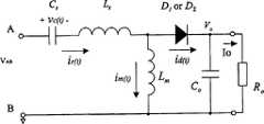
Fig. 5 is the equivalent electric circuit of the LLC resonance DC/DC converter of Fig. 4;
Fig. 6 has shown that LLC resonance DC/DC converter is at f=fsThe time waveform;
Fig. 7 has shown that LLC resonance DC/DC converter is at fm<f<fsThe time waveform;
Fig. 8 has shown that LLC resonance DC/DC converter is at f>fsThe time waveform;
Fig. 9 is the circuit of deriving: resonance inductor is incorporated in the transformer;
Figure 10 is a converter of the present invention has a full-bridge rectifier at outlet side a circuit diagram;
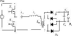
Figure 11 is a converter of the present invention has a full-bridge inverter at input side a circuit diagram; And
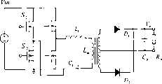
Figure 12 is the circuit diagram that a converter of the present invention has two half-bridges of a serial connection.
Embodiment
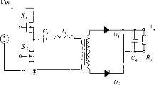
Fig. 4 has shown the electrical schematic diagram of LLC resonance series DC/DC converter of the present invention.This novel resonate converter comprisessquarer 110,LLC resonance network 120,high frequency transformer 130,rectification circuit 140 and output filter 150.Squarer circuit 110 is a half-bridge inverter and contains two switches (S1 and S2).Except a half-bridge inverter, also may use a full-bridge inverter to replace half-bridge circuit.120 cross-over connections of LLC resonance network receive square-wave signal in two terminals (that is terminal A and B) of second switch S2 in alternately switching on and off atswitch S 1 and S2.LLC resonance circuit 120 comprises series capacitor CsBe serially connected with a series connection inductor LsLLC resonance circuit 120 also comprises an inductor L in parallelmBe connected to the first side winding of transformer 130.Series capacitor C in this resonance networksTwo functions are arranged.The first, series capacitor CsStop voltage V with the square-wave signal inputABDC component lead to transformer 130.Series capacitor CsAlso with series reactor LsWith shunt inductance device LmForm a resonance circuit.Series reactor LsGet and be implemented as an external assembly as shown in Figure 4, or be implemented as the leakage inductance of transformer.In addition, shunt inductance device LmAlso can be implemented as an external inductor or be the magnetizing inductance oftransformer 130.
Be coupled tohigh frequency transformer 130 that secondary side winding constitutes by first side winding and provide coupling and insulation for the output voltage of this converter.Rectification circuit 140 (it comprises diode D1 and D2) forms a centre cap rectifier, and resonance current is transformed into unidirectional current.Also can use a full-bridge rectifier to replace the centre caprectifier.Output filter 150 comprises a capacitor CoFiltering dither electric current and provide a pulse free constant output voltage V across output loadingo
According to the present invention, the lock control signal that puts onswitch S 1 and S2 is complementary.The duty ratio of any one is 50% in this two complementary signal.Use Variable Operating Frequency control to regulate output voltage V alternately to switch on and off this two switchoWith reference to the operating characteristic of Fig. 5 with an equivalent circuit description LLC resonate converter.In particular, as shown in the figure, it is this first characteristic resonance frequency f that the modern resonance DC/DC converter of implementing with the LLC resonance network has two characteristic frequency pointssWith the second characteristic resonance frequency fm:
The operation principle of LLC resonate converter is able to three cases and is illustrated:
(1)f=fs
Show when switching frequency f and resonance series frequency f with reference to Fig. 6sLLC resonate converter work wave when identical.As voltage V across terminal A and BABAt no-voltage and input voltage VInBetween with frequency fsDuring switching, show the resonance circuit current i among the figurer(t) be a sinusoidal waveform.Across series capacitor CsVoltage vc(t) high fdrequency component also has a pure sinusoid waveform.By shunt inductance device LmCurrent im(t) be synchronized with VABSwitching increase with a linear function and reduce.Input voltage VInWith output voltage VoBetween relation represent with following formula:
Wherein n is a transformer voltage ratio, and it is defined as the ratio of the first side winding number of turn oftransformer 130 to the secondary side winding number of turn.
(2)fm<f<fs
With reference to Fig. 7 display switch frequency (that is f between two characteristic resonance frequenciesm<f<fs) time LLC resonate converter work wave.When the voltage acrossswitch S 2 is height, i.e. VAB=VIn, input direct voltage puts onresonance circuit 120, and electric current resonates at Ls and Cs, and is fed to outlet side with sinusoidal wave form.T in half period of resonance series1/ 2 time points, the current i d (t) by rectifier diodes drops to zero.The outlet side rectifier reply naturally and resonance transfer to CsAnd Ls+ LmBetween.In this mode of operation, resonance current continues resonating capacitor CsCharging.Because LmMore than LsGreatly, resonance current at this moment apart from be almost constant.
When switchS 1 for disconnect and switchS 2 when connecting, voltage VABReduce to zero, Ls, LmAnd CsBetween resonance by being stored in resonating capacitor CsInterior energy starting.Waveform roughly is symmetrical in the preceding half period.The input and output voltage between concern to such an extent that be expressed as:
I whereinmPeak value for magnetizing current , T1Be the cycle of resonance series
 And T is the cycle corresponding to switching frequency.Therefore, output voltage can strengthen with switch periods T and improve, and is able to keeping constant output voltage V than low input work by strengthening switch periods T according to equation (4)o


This is for the typical case and the characteristic mode of operation of LLC resonance series DC/DC converter of the present invention.Because higher magnetizing current, the ZVS condition of main switch is satisfied in the gamut of input voltage and output loading.And the secondary side rectifier is because of with than the first characteristic resonance frequency f during this periodsLow frequency is switched and is worked under the ZCS condition.
(3)f>fs
Demonstration is worked as switching frequency f than the first characteristic resonance frequency f with reference to Fig. 8s(that is f>f greatlys) time LLC resonate converter work wave, the work of LLC resonance series DC/DC converter of the present invention can be degenerated to a known resonance series converter.Whenswitch S 1 and S2 complementally are switched on or switched off only at LsAnd CsBetween a resonance appears, at Ls, LmAnd CsBetween no longer include resonance.
Can recognize from above detailed description, with regard to traditional resonance DC/DC converter, conversion efficiency can be in low input service by converter with characteristic resonance frequency fsSwitch and optimization, and switching frequency can be higher to regulate output voltage when height is imported, and so causes low conversion efficiency work.With regard to LLC resonance series DC/DC converter of the present invention, be able to the lower frequency switch application in converter to regulate output voltage in low input service, the output voltage of cf. equation (4) is regulated, therefore can be at high initial conditions by converter with characteristic resonance frequency fsSwitch and the best turns to maximum.In addition, this LLC resonance series DC/DC converter also presents much lower switching loss because of the zero voltage switch of primary side switch and the Zero Current Switch of secondary side rectifier at high-frequency work, so converter of the present invention must reach much higher conversion efficiency compared with known resonate converter or pwm converter.
Being able to several circuit structures according to the present invention who describes structure and functional character as Fig. 4 to Fig. 8 implements.First embodiment of circuit structure is shown in Fig. 9, wherein series reactor LsWith shunt inductance device LmBe integrated in the transformer 130.Figure 10 shows a replacement circuit of the present invention, and it possesses full-bridge rectifier, wherein can require single winding in Circuit Fault on Secondary Transformer.Figure 11 shows that one possesses another embodiment of the circuit structure of the present invention of full-bridge inverter.This circuit is applicable to high power applications.Figure 12 shows another different circuit embodiments of the present invention, and it possesses two half-bridges of serial connection.This circuit is applicable to the application of high input voltage and/or high power system.
With regard to essence, the present invention discloses a kind of DC/DC converter, and it comprises a resonance loop and comprises the resonant circuit that two resonance characteristics frequencies are provided.In a preferred embodiment, this resonance circuit comprises that a series connection capacitor is connected in a series connection inductor and an inductor in parallel is connected to load.This series capacitor and this series reactor effect provide first characteristic resonance frequency with fsExpression, and this series capacitor and this series reactor and the effect of shunt inductance device provide second characteristic resonance frequency with fmExpression, wherein fs>fmIn preferred embodiment, this first characteristic resonance frequency is And second characteristic resonance frequency is
 C whereinsRepresent the electric capacity of series capacitor, LsRepresent the inductance and the L of series reactormRepresent the inductance of shunt inductance device.In another preferred embodiment, utilize the magnetizing inductance of transformer to be used as the shunt inductance device and not need an external shunt inductance device, utilize the leakage inductance of transformer to be used as series reactor and not need an external series inductance in addition.


Though with regard to present preferred embodiment explanation the present invention, should be appreciated that these description should not be construed as restricted meaning.Be familiar with present technique field person and after the above description of reading, will appreciate that numerous replacement schemes and modification without doubt.Therefore, pre-interim claims scope is to be illustrated as all replacement schemes and the modification that is encompassed in true spirit of the present invention and the scope.
Claims (14)
1. DC/DC converter, it comprises:
One squarer, it is used for producing a series of output voltages with a square-wave waveform;
One resonance loop, it is connected in this squarer, and this resonance circuit comprises that a series connection capacitor is connected in a series connection inductor and an inductor in parallel;
One transformer, its once side be serially connected with this series reactor and be connected to this shunt inductance device;
This transformer also comprise secondary side be used for being connected in a rectification circuit with an output loading circuit is provided one commutated direct current press;
This rectification circuit also comprise a filtering capacitor be used for filtering to this output load current output this commutated direct current press;
This series capacitor and this series reactor effect and provide first characteristic resonance frequency with fsExpression, and this series capacitor and this series reactor and this shunt inductance device effect and provide second characteristic resonance frequency with fmExpression, wherein fs>fm
This converter is higher than this second frequency f onemFrequency range in the running.
2. DC/DC converter as claimed in claim 1 is characterized in that:
Operating frequency (f between this first and second frequency when this DC/DC converterm<f<fs) time, the switch in this squarer under the zero voltage switching condition, work and this rectification circuit in rectifier in the work down of zero current switching condition.
3. DC/DC converter as claimed in claim 1 is characterized in that:
This rectification circuit comprises a center-tap rectifier circuit.
4. DC/DC converter as claimed in claim 1 is characterized in that:
This rectification circuit comprises a full bridge rectifier.
5. DC/DC converter as claimed in claim 1 is characterized in that:
This shunt inductance device is implemented as an external inductor.
6. DC/DC converter as claimed in claim 1 is characterized in that:
This shunt inductance device is implemented as a magnetizing inductance of this transformer.
7. DC/DC converter as claimed in claim 1 is characterized in that:
This series reactor is implemented as an external inductor.
8. DC/DC converter as claimed in claim 1 is characterized in that:
This series reactor is implemented as a leakage inductance of this transformer.
9. DC/DC converter as claimed in claim 1 is characterized in that:
This squarer comprises that first switch and second switch are complementary to this first switch and are used for alternately switching on and off to produce this square-wave voltage.
10. DC/DC converter as claimed in claim 1 is characterized in that:
This squarer comprises that four switches connect into a full bridge structure to produce square-wave voltage.
11. DC/DC converter as claimed in claim 1 is characterized in that:
This squarer comprises that two half-bridges are serially connected to produce square-wave voltage.
12. a resonance circuit, it is connected in the first side winding of transformer in the DC/DC converter, and this resonance circuit comprises:
One series connection capacitor series is in a series connection inductor and an inductor in parallel;
This shunt inductance device is connected to this transformer first side winding;
This series capacitor and this series reactor effect and provide first characteristic resonance frequency with fsExpression, and this series capacitor and this series reactor and this shunt inductance device effect and provide second characteristic resonance frequency with fmExpression, wherein fs>fmAnd
This DC/DC converter is higher than this second frequency f in onemBe lower than this first characteristic frequency fsFrequency range in the running.
13. resonance circuit as claimed in claim 12 is characterized in that:
This shunt inductance device is integrated in the magnetizing inductance of this transformer.
14. resonance circuit as claimed in claim 12 is characterized in that:
This series reactor is integrated in the leakage inductance of this transformer.
Applications Claiming Priority (2)
| Application Number | Priority Date | Filing Date | Title |
|---|---|---|---|
| US09/780128 | 2001-02-09 | ||
| US09/780,128US6344979B1 (en) | 2001-02-09 | 2001-02-09 | LLC series resonant DC-to-DC converter |
Publications (2)
| Publication Number | Publication Date |
|---|---|
| CN1368787Atrue CN1368787A (en) | 2002-09-11 |
| CN1242539C CN1242539C (en) | 2006-02-15 |
Family
ID=25118699
Family Applications (1)
| Application Number | Title | Priority Date | Filing Date |
|---|---|---|---|
| CNB011394455ACeasedCN1242539C (en) | 2001-02-09 | 2001-11-22 | LLC series resonant DC/DC converter |
Country Status (3)
| Country | Link |
|---|---|
| US (1) | US6344979B1 (en) |
| CN (1) | CN1242539C (en) |
| TW (1) | TW533669B (en) |
Cited By (37)
| Publication number | Priority date | Publication date | Assignee | Title |
|---|---|---|---|---|
| WO2008101367A1 (en)* | 2007-02-17 | 2008-08-28 | Zhejiang University | Magnetic integration structure |
| CN100424975C (en)* | 2005-02-25 | 2008-10-08 | 台达电子工业股份有限公司 | LLC series resonant converter and synchronous rectification power switch driving method thereof |
| CN100553094C (en)* | 2004-04-26 | 2009-10-21 | 雅达电子国际有限公司 | Coupled inductor current doubler and power converter including the same |
| CN1523746B (en)* | 2003-09-03 | 2010-04-14 | 浙江大学 | Three-level LLC series resonant DC/DC converter |
| CN101841244A (en)* | 2009-03-20 | 2010-09-22 | 力博特公司 | Low output loss LLC resonant converter |
| CN101888187A (en)* | 2009-05-11 | 2010-11-17 | 英特赛尔美国股份有限公司 | Control Mode of ZVS Converter at Resonant Operating Frequency |
| CN102025266A (en)* | 2009-06-18 | 2011-04-20 | 力博特公司 | Numeric control method for liquid level control (LLC) resonant conversion circuit |
| CN102204073A (en)* | 2008-10-27 | 2011-09-28 | Abb研究有限公司 | Converter circuit and unit and system having such a converter circuit |
| CN102545614A (en)* | 2010-12-16 | 2012-07-04 | 台达电子工业股份有限公司 | Resonant power conversion circuit |
| CN102651939A (en)* | 2011-02-28 | 2012-08-29 | Nxp股份有限公司 | Electrical load driving circuit |
| CN101036284B (en)* | 2004-10-01 | 2012-11-28 | 皇家飞利浦电子股份有限公司 | Power converter for LED large area light source lamp |
| CN1747300B (en)* | 2004-07-21 | 2012-12-05 | 普尔有限公司 | Method for adjusting or controlling resonance transducer and switch power device |
| CN101666823B (en)* | 2008-09-04 | 2013-01-30 | 力博特公司 | Current detection method and device for LLC resonance circuit |
| CN103582996A (en)* | 2011-06-07 | 2014-02-12 | 西门子公司 | Open-loop control of a contactless energy transmission by means of a characteristic curve of a resonant circuit |
| US8717782B2 (en) | 2009-01-07 | 2014-05-06 | Texas Instruments Incorporated | Sweeping frequency LLC resonant power regulator |
| CN103840671A (en)* | 2012-11-20 | 2014-06-04 | 三星电机株式会社 | Multi-output power supply |
| CN103840657A (en)* | 2012-11-23 | 2014-06-04 | 台达电子工业股份有限公司 | Voltage Balancing Method for Power Converter and Input Capacitor |
| CN103856079A (en)* | 2012-11-28 | 2014-06-11 | 台达电子企业管理(上海)有限公司 | Switching power-conversion circuit and power supply device for the same |
| CN104135154A (en)* | 2014-08-05 | 2014-11-05 | 浙江大学 | Isolated four-element resonance circuit and control method |
| CN104871422A (en)* | 2012-12-21 | 2015-08-26 | 斯堪的诺维亚系统公司 | Capacitor charger system, power modulator and resonant power converter |
| CN105119495A (en)* | 2009-12-28 | 2015-12-02 | 意法半导体股份有限公司 | Charge-mode control device for a resonant converter |
| CN105207483A (en)* | 2014-05-30 | 2015-12-30 | 纬创资通股份有限公司 | Llc resonant power converter |
| CN105356779A (en)* | 2015-12-18 | 2016-02-24 | 北京理工大学 | Diode clamp power switch series-connection high-voltage inverter and topological structure thereof |
| CN105406722A (en)* | 2015-12-18 | 2016-03-16 | 北京理工大学 | High-voltage direct-current transformer connected with diode clamping power switch in series |
| US9331565B2 (en) | 2010-07-14 | 2016-05-03 | Delta Electronics (Shanghai) Co., Ltd. | Switching power conversion circuit and power supply using same |
| CN105576978A (en)* | 2014-11-05 | 2016-05-11 | 英飞凌科技奥地利有限公司 | Secondary side control of resonant DC/DC converters |
| CN105634287A (en)* | 2009-12-28 | 2016-06-01 | 意法半导体股份有限公司 | Charge-mode control device for a resonant converter |
| WO2016150245A1 (en)* | 2015-03-23 | 2016-09-29 | 深圳市皓文电子有限公司 | Dc/dc converter |
| CN106849686A (en)* | 2017-03-13 | 2017-06-13 | 合肥工业大学 | Bicyclic fixed-frequency control method based on BUCK LLC two-stage DC/DC converters |
| WO2017185856A1 (en)* | 2016-04-29 | 2017-11-02 | 华为技术有限公司 | Resonant power converter and frequency tracking method therefor |
| WO2018120817A1 (en)* | 2016-12-29 | 2018-07-05 | 广东美的厨房电器制造有限公司 | Frequency converter and microwave oven |
| CN108471238A (en)* | 2018-03-21 | 2018-08-31 | 上海钧功电子科技有限公司 | A kind of converter |
| CN108964478A (en)* | 2018-09-19 | 2018-12-07 | 矽力杰半导体技术(杭州)有限公司 | Resonant Switching Converter |
| CN108962556A (en)* | 2017-05-26 | 2018-12-07 | 株式会社搜路研 | Transformer and LLC resonance converter with the transformer |
| CN109831097A (en)* | 2019-02-25 | 2019-05-31 | 洛阳隆盛科技有限责任公司 | A kind of voltage-dropping power supply circuit and method based on the conversion of two-stage cascade voltage |
| WO2021068776A1 (en)* | 2019-10-09 | 2021-04-15 | 中兴通讯股份有限公司 | Soft starting method for resonant converter, circuit and apparatus |
| CN114079384A (en)* | 2021-11-02 | 2022-02-22 | 西安交通大学 | Variable-structure LLC converter with wide output voltage range and method |
Families Citing this family (113)
| Publication number | Priority date | Publication date | Assignee | Title |
|---|---|---|---|---|
| US6807073B1 (en) | 2001-05-02 | 2004-10-19 | Oltronics, Inc. | Switching type power converter circuit and method for use therein |
| DE10122534A1 (en)* | 2001-05-09 | 2002-11-21 | Philips Corp Intellectual Pty | Resonant converter |
| EP1257048B1 (en)* | 2001-05-09 | 2017-10-04 | Philips Lighting Holding B.V. | Regulation device for a resonant converter |
| DE10128687A1 (en)* | 2001-06-13 | 2002-12-19 | Philips Corp Intellectual Pty | DC converter |
| JP2005524375A (en)* | 2002-04-23 | 2005-08-11 | コーニンクレッカ フィリップス エレクトロニクス エヌ ヴィ | LLC half-bridge converter |
| GB2393336B (en)* | 2002-09-20 | 2005-07-20 | Coutant Lambda Ltd | Multi-resonant power conversion apparatus and methods |
| US8253394B2 (en) | 2004-02-17 | 2012-08-28 | Hewlett-Packard Development Company, L.P. | Snubber circuit |
| US20050162870A1 (en)* | 2004-01-23 | 2005-07-28 | Hirst B. M. | Power converter |
| WO2005091483A1 (en)* | 2004-03-18 | 2005-09-29 | Mitsui & Co., Ltd. | Dc-dc converter |
| US7518263B2 (en)* | 2004-04-12 | 2009-04-14 | Delta Electronics, Inc. | Time delay control scheme for a power supply with multiple outputs |
| KR20070012529A (en)* | 2004-05-05 | 2007-01-25 | 코닌클리케 필립스 일렉트로닉스 엔.브이. | Identification system using mechanical vibrations on identifiers |
| JP4762134B2 (en)* | 2004-05-07 | 2011-08-31 | パナソニック株式会社 | Resonant switching power supply |
| EP1771937A1 (en)* | 2004-07-21 | 2007-04-11 | Koninklijke Philips Electronics N.V. | Automatic frequency control for series resonant switched mode power supply |
| WO2006013500A1 (en)* | 2004-07-26 | 2006-02-09 | Koninklijke Philips Electronics N.V. | Converter for providing several output voltages |
| US7489526B2 (en)* | 2004-08-20 | 2009-02-10 | Analog Devices, Inc. | Power and information signal transfer using micro-transformers |
| US7558080B2 (en)* | 2004-08-20 | 2009-07-07 | Analog Devices, Inc. | Power converter system |
| US7133298B2 (en)* | 2004-10-25 | 2006-11-07 | Texas Instruments Incorporated | High frequency voltage regulating transformer based converter |
| EP1820256A1 (en)* | 2004-11-29 | 2007-08-22 | Philips Intellectual Property & Standards GmbH | Multi-resonance converter |
| FR2884075A1 (en)* | 2005-04-04 | 2006-10-06 | Thomson Licensing Sa | CONTINUOUSLY SWITCHED VOLTAGE CONVERTER |
| US7310245B2 (en)* | 2005-04-22 | 2007-12-18 | Noboru Ohbo | Electric power transmission device and electric power transmission method |
| KR100547289B1 (en)* | 2005-05-18 | 2006-01-26 | 주식회사 피에스텍 | Synchronous Rectified Series Resonant Converter Operates in Intermittent Mode |
| US7554820B2 (en)* | 2005-09-20 | 2009-06-30 | Harman International Industries, Incorporated | Series resonant DC-DC converter |
| US7952892B2 (en)* | 2006-04-04 | 2011-05-31 | Power Integrations, Inc. | DC converters with constant and variable duty ratio switching |
| WO2007148271A2 (en)* | 2006-06-20 | 2007-12-27 | Koninklijke Philips Electronics N.V. | Method for operating a resonant power converter |
| US20080048577A1 (en)* | 2006-08-26 | 2008-02-28 | Matthew Beasley | Projector HID lam ballast having LLC resonant converter |
| US20080048578A1 (en)* | 2006-08-26 | 2008-02-28 | Matthew Beasley | Projector HID lamp ballast having auxiliary resonant circuit |
| WO2008029343A2 (en)* | 2006-09-08 | 2008-03-13 | Bobinados De Transformadores S.L. | Resonant power converter |
| JP4222421B2 (en) | 2007-02-28 | 2009-02-12 | サンケン電気株式会社 | Multi-output switching power supply |
| TWI340528B (en)* | 2007-04-03 | 2011-04-11 | Delta Electronics Inc | Resonant converter system and controlling method thereof having relatively better efficiency |
| CN101064484A (en)* | 2007-04-19 | 2007-10-31 | 唯冠科技(深圳)有限公司 | Electric power apparatus and light modulation method |
| CN101373933B (en)* | 2007-08-24 | 2011-11-23 | 力博特公司 | Half-bridge converter with balance capability and control method thereof |
| WO2009034180A1 (en)* | 2007-09-12 | 2009-03-19 | Texas Instruments (Cork) Limited | A power converter |
| KR100967048B1 (en)* | 2007-12-07 | 2010-06-29 | 삼성전기주식회사 | DC power supply that changes output voltage according to load current change |
| EP2073366B1 (en)* | 2007-12-18 | 2016-04-27 | ABB Research Ltd. | dc-dc converter with resonant converter |
| KR101378568B1 (en)* | 2008-01-04 | 2014-03-27 | 페어차일드코리아반도체 주식회사 | Synchronous Rectifier |
| US8339817B2 (en)* | 2008-02-04 | 2012-12-25 | Nxp B.V. | Method of operating a resonant power converter and a controller therefor |
| DE102008028952A1 (en) | 2008-06-18 | 2009-12-24 | Abb Ag | AC-DC DC link converter with very wide AC input voltage range |
| PL217714B1 (en)* | 2008-06-20 | 2014-08-29 | Akademia Górniczo Hutnicza Im Stanisława Staszica | Multiresonance feeder with integral quality factor limiter |
| KR100966972B1 (en)* | 2008-07-17 | 2010-06-30 | 삼성전기주식회사 | Variable switching frequency power supply |
| WO2010020909A1 (en)* | 2008-08-21 | 2010-02-25 | Nxp B.V. | Load current detection in electrical power converters |
| JP2010086943A (en)* | 2008-09-04 | 2010-04-15 | Toshiba Lighting & Technology Corp | Led lighting device and illumination fixture |
| KR100997397B1 (en)* | 2008-10-23 | 2010-11-30 | 주식회사 디엠비테크놀로지 | Inverter system and its operation method |
| US9166489B2 (en)* | 2009-02-27 | 2015-10-20 | Delta Electronics (Shanghai) Co., Ltd. | Layouts of multiple transformers and multiple rectifiers of interleaving converter |
| US20120268976A1 (en)* | 2009-02-27 | 2012-10-25 | Delta Electronics (Shanghai) Co., Ltd. | Three-phase rectifier circuit |
| WO2010115976A1 (en)* | 2009-04-09 | 2010-10-14 | Stmicroelectronics S.R.L. | Method and circuit for avoiding hard switching in resonant converters |
| US8391026B2 (en)* | 2009-04-09 | 2013-03-05 | Stmicroelectronics S.R.L. | Method and circuit for avoiding hard switching in resonant converters |
| EP2262088A1 (en) | 2009-06-10 | 2010-12-15 | ABB Research Ltd. | DC-DC converter |
| EP2262087A1 (en) | 2009-06-10 | 2010-12-15 | ABB Research Ltd. | Converter circuit |
| CN101931329B (en)* | 2009-06-23 | 2013-04-17 | 力博特公司 | Method and system for optimizing efficiency of LLC ((Logical Link Control) topology and LLC topology system |
| EP2449665B1 (en)* | 2009-07-03 | 2015-09-23 | Koninklijke Philips N.V. | Low cost power supply circuit and method |
| US9166488B2 (en)* | 2009-10-30 | 2015-10-20 | Delta Electronics Inc. | Method and apparatus for resetting a resonant converter |
| KR101035017B1 (en) | 2009-12-01 | 2011-05-17 | 주식회사 애버드랩스 | ELC Half Bridge Power Converter for LED |
| TWI420792B (en)* | 2010-02-11 | 2013-12-21 | Delta Electronics Inc | Resonant converters and burst mode control methods thereof |
| US9059636B2 (en)* | 2010-02-18 | 2015-06-16 | Peter Waldemar Lehn | DC-DC converter circuit using LLC circuit in the region of voltage gain above unity |
| US20150162840A1 (en)* | 2010-02-18 | 2015-06-11 | Arda Power Inc | Dc-dc converter circuit using an llc circuit in the region of voltage gain above unity |
| AU2011217688A1 (en) | 2010-02-18 | 2012-10-11 | Peter Waldemar Lehn | DC-DC converter circuit for high input-to-output voltage conversion |
| US8369116B2 (en)* | 2010-03-01 | 2013-02-05 | Raymond Peter Maroon | Isolated DC-to-DC power converter topology |
| US8665611B2 (en)* | 2010-04-30 | 2014-03-04 | Infineon Technologies Ag | Controller for a resonant switched-mode power converter |
| KR101116498B1 (en) | 2010-06-07 | 2012-02-27 | 삼성에스디아이 주식회사 | Energy storage system |
| KR20110138068A (en)* | 2010-06-18 | 2011-12-26 | 페어차일드코리아반도체 주식회사 | Power factor correction converter and its driving method |
| US8629627B2 (en)* | 2010-06-29 | 2014-01-14 | Texas Instruments Incorporated | Multi-transformer LLC resonant converter circuits and methods |
| CN102340251B (en) | 2010-07-20 | 2014-06-04 | 台达电子工业股份有限公司 | AC-DC converter and its control circuit |
| CN102468759B (en)* | 2010-11-01 | 2015-02-18 | 台达电子工业股份有限公司 | Resonant converter and its reset method and device |
| KR101264024B1 (en) | 2010-12-22 | 2013-05-13 | 삼성전기주식회사 | Control circuit of llc resonant converter and llc resonant converter using the same |
| US20120176817A1 (en)* | 2011-01-07 | 2012-07-12 | Texas Instruments Incorporated | Dc-dc converter |
| CN202034832U (en)* | 2011-04-08 | 2011-11-09 | 东南大学 | Non-contact power transmitting device with self-adaptation power factor correction function |
| US9948204B2 (en)* | 2011-05-19 | 2018-04-17 | Enphase Energy, Inc. | Method and apparatus for controlling resonant converter output power |
| CN102857103A (en)* | 2011-06-30 | 2013-01-02 | 艾默生网络能源系统北美公司 | Three-level LLC (Logical Link Control) direct-current converter and control method thereof |
| EP2568589B1 (en) | 2011-09-08 | 2013-11-13 | ABB Technology AG | Multilevel converter comprising an active AC-DC converter and a resonant DC-DC converter and a control method for operating a multilevel converter |
| CN103782499A (en)* | 2011-09-09 | 2014-05-07 | 株式会社村田制作所 | Isolated switch-mode dc/dc converter with sine wave transformer voltages |
| US8723428B2 (en)* | 2011-11-17 | 2014-05-13 | General Electric Company | LED power source with over-voltage protection |
| TWI456885B (en) | 2011-12-06 | 2014-10-11 | Ind Tech Res Inst | A dc-to-dc voltage regulator and the operating method thereof |
| KR20130082016A (en)* | 2012-01-10 | 2013-07-18 | 삼성전자주식회사 | Display apparatus and diriving method using the same |
| CN102545638B (en)* | 2012-01-20 | 2016-03-30 | 华为技术有限公司 | Crisscross parallel three level DC/DC converter and AC/DC converter |
| WO2014049517A2 (en)* | 2012-09-26 | 2014-04-03 | Koninklijke Philips N.V. | Light emitting diode lamp and driver |
| WO2014060872A1 (en)* | 2012-10-18 | 2014-04-24 | Koninklijke Philips N.V. | Driver device and driving method for driving a load, in particular an led unit, using a resonant converter |
| KR101376787B1 (en) | 2012-11-27 | 2014-03-25 | 경북대학교 산학협력단 | Resonant converters having digital control |
| US9515562B2 (en) | 2013-03-05 | 2016-12-06 | Futurewei Technologies, Inc. | LLC resonant converters |
| US9190911B2 (en) | 2013-03-05 | 2015-11-17 | Futurewei Technologies, Inc. | Auxiliary resonant apparatus for LLC converters |
| US9293997B2 (en) | 2013-03-14 | 2016-03-22 | Analog Devices Global | Isolated error amplifier for isolated power supplies |
| KR101532131B1 (en)* | 2013-04-29 | 2015-06-26 | 삼성전기주식회사 | Resonant type power supplying apparatus |
| AT13856U1 (en)* | 2013-04-30 | 2014-10-15 | Tridonic Gmbh & Co Kg | Method for operating an LED converter |
| TWI552494B (en)* | 2013-07-01 | 2016-10-01 | 國立虎尾科技大學 | High voltage rectifier with double current output |
| US10188446B2 (en)* | 2013-10-16 | 2019-01-29 | Covidien Lp | Resonant inverter |
| KR101465431B1 (en)* | 2014-01-23 | 2014-11-27 | 성균관대학교산학협력단 | Power conversion device and control method for semiconductor switches |
| US9548668B2 (en)* | 2014-03-14 | 2017-01-17 | Futurewei Technologies, Inc. | Hybrid power converter and method |
| GB2524102A (en)* | 2014-03-14 | 2015-09-16 | Eisergy Ltd | A switched mode AC-DC converter |
| JP6232341B2 (en)* | 2014-05-09 | 2017-11-15 | 東芝テック株式会社 | Power converter |
| KR101491766B1 (en) | 2014-07-22 | 2015-02-11 | 성균관대학교산학협력단 | Power conversion device and control method for semiconductor switches |
| US9257913B1 (en) | 2014-09-06 | 2016-02-09 | Texas Instruments Incorporated | LLC converter and loss of inductive mode detection circuit |
| US9660848B2 (en) | 2014-09-15 | 2017-05-23 | Analog Devices Global | Methods and structures to generate on/off keyed carrier signals for signal isolators |
| US10536309B2 (en) | 2014-09-15 | 2020-01-14 | Analog Devices, Inc. | Demodulation of on-off-key modulated signals in signal isolator systems |
| US10270630B2 (en) | 2014-09-15 | 2019-04-23 | Analog Devices, Inc. | Demodulation of on-off-key modulated signals in signal isolator systems |
| US9998301B2 (en) | 2014-11-03 | 2018-06-12 | Analog Devices, Inc. | Signal isolator system with protection for common mode transients |
| EP3133614B1 (en) | 2015-08-18 | 2019-11-20 | Delta Electronics (Thailand) Public Co., Ltd. | Integrated magnetic component |
| US10003275B2 (en) | 2016-11-11 | 2018-06-19 | Texas Instruments Incorporated | LLC resonant converter with integrated magnetics |
| CN106972750B (en)* | 2017-03-16 | 2018-08-10 | 合肥工业大学 | Tricyclic fixed-frequency control method based on BUCK-LLC two-stage DC/DC converters |
| US10381914B2 (en) | 2017-07-19 | 2019-08-13 | Texas Instruments Incorporated | Integrated transformer |
| US10277140B2 (en) | 2017-08-31 | 2019-04-30 | Google Llc | High-bandwith resonant power converters |
| US10298138B2 (en) | 2017-08-31 | 2019-05-21 | Google Llc | Programmable power adapter |
| TWI641210B (en)* | 2017-09-08 | 2018-11-11 | 昱京能源科技股份有限公司 | PSR current control system under LLC architecture |
| IL255948A (en)* | 2017-11-27 | 2018-01-31 | Abramovici Tal | Constant frequency dc/dc power converter |
| US11901826B2 (en)* | 2019-08-26 | 2024-02-13 | Delta Electronics, Inc. | Isolated DC/DC converters for wide output voltage range and control methods thereof |
| ES2913635T3 (en) | 2019-09-20 | 2022-06-03 | Hitachi Energy Switzerland Ag | Dual active bridge converter cell with split power transfer inductor for optimized current balancing in the medium frequency transformer (MFT) |
| US11532989B2 (en) | 2019-11-27 | 2022-12-20 | Hamilton Sundstrand Corporation | Using parasitic capacitance of a transformer as a tank element in a DC-DC converter |
| TWI814025B (en) | 2020-06-30 | 2023-09-01 | 台達電子工業股份有限公司 | Dc-dc resonant converter and control method thereof |
| US11855529B2 (en) | 2020-09-11 | 2023-12-26 | Board Of Trustees Of The University Of Arkansas | PWM-controlled three level stacked structure LLC resonant converter and method of controlling same |
| US11496056B2 (en) | 2021-03-10 | 2022-11-08 | Excelsys Technologies Ltd. | Parallel branched resonant converter |
| US20230061145A1 (en)* | 2021-08-24 | 2023-03-02 | Monolithic Power Systems, Inc. | Llc resonant converter with direct power transformer |
| CN113794381B (en)* | 2021-09-16 | 2023-05-23 | 国网山西省电力公司电力科学研究院 | SCDAB-CLLLC composite direct-current transformer with wide voltage regulation range and control method thereof |
| US11901828B2 (en)* | 2022-02-16 | 2024-02-13 | Zhejiang University | Bidirectional CLLC resonant circuit with coupled inductor |
| EP4312356A1 (en) | 2022-07-28 | 2024-01-31 | Collins Aerospace Ireland, Limited | Series resonant power converter |
| CN118889860B (en)* | 2024-09-30 | 2025-01-28 | 中南大学 | A single-stage converter for step-down conversion and control method |
Family Cites Families (11)
| Publication number | Priority date | Publication date | Assignee | Title |
|---|---|---|---|---|
| US4785387A (en)* | 1986-04-28 | 1988-11-15 | Virginia Tech Intellectual Properties, Inc. | Resonant converters with secondary-side resonance |
| US4814962A (en)* | 1988-05-27 | 1989-03-21 | American Telephone And Telegraph Company, At&T Bell Laboratories | Zero voltage switching half bridge resonant converter |
| US4876635A (en)* | 1988-12-23 | 1989-10-24 | General Electric Company | Series resonant inverter with lossless snubber-resetting components |
| US5388040A (en)* | 1993-09-30 | 1995-02-07 | Hughes Aircraft Company | Series resonant converter having an actively controlled third element |
| US5438498A (en)* | 1993-12-21 | 1995-08-01 | Raytheon Company | Series resonant converter having a resonant snubber |
| DE19529941A1 (en)* | 1995-08-16 | 1997-02-20 | Philips Patentverwaltung | Voltage converter |
| JP2792536B2 (en)* | 1995-09-26 | 1998-09-03 | 日本電気株式会社 | Resonant DC-DC converter |
| US5684678A (en)* | 1995-12-08 | 1997-11-04 | Delco Electronics Corp. | Resonant converter with controlled inductor |
| US5781418A (en)* | 1996-12-23 | 1998-07-14 | Philips Electronics North America Corporation | Switching scheme for power supply having a voltage-fed inverter |
| US5986895A (en)* | 1998-06-05 | 1999-11-16 | Astec International Limited | Adaptive pulse width modulated resonant Class-D converter |
| US6137234A (en)* | 1999-10-18 | 2000-10-24 | U.S. Philips Corporation | Circuit arrangement |
- 2001
- 2001-02-09USUS09/780,128patent/US6344979B1/ennot_activeExpired - Lifetime
- 2001-09-14TWTW090122934Apatent/TW533669B/ennot_activeIP Right Cessation
- 2001-11-22CNCNB011394455Apatent/CN1242539C/ennot_activeCeased
Cited By (58)
| Publication number | Priority date | Publication date | Assignee | Title |
|---|---|---|---|---|
| CN1523746B (en)* | 2003-09-03 | 2010-04-14 | 浙江大学 | Three-level LLC series resonant DC/DC converter |
| CN100553094C (en)* | 2004-04-26 | 2009-10-21 | 雅达电子国际有限公司 | Coupled inductor current doubler and power converter including the same |
| CN1747300B (en)* | 2004-07-21 | 2012-12-05 | 普尔有限公司 | Method for adjusting or controlling resonance transducer and switch power device |
| CN101036284B (en)* | 2004-10-01 | 2012-11-28 | 皇家飞利浦电子股份有限公司 | Power converter for LED large area light source lamp |
| CN100424975C (en)* | 2005-02-25 | 2008-10-08 | 台达电子工业股份有限公司 | LLC series resonant converter and synchronous rectification power switch driving method thereof |
| WO2008101367A1 (en)* | 2007-02-17 | 2008-08-28 | Zhejiang University | Magnetic integration structure |
| CN101666823B (en)* | 2008-09-04 | 2013-01-30 | 力博特公司 | Current detection method and device for LLC resonance circuit |
| CN102204073A (en)* | 2008-10-27 | 2011-09-28 | Abb研究有限公司 | Converter circuit and unit and system having such a converter circuit |
| CN102204073B (en)* | 2008-10-27 | 2014-05-07 | Abb研究有限公司 | Converter circuit and unit and system having such a converter circuit |
| US8717782B2 (en) | 2009-01-07 | 2014-05-06 | Texas Instruments Incorporated | Sweeping frequency LLC resonant power regulator |
| CN102047549B (en)* | 2009-01-07 | 2018-05-04 | 德克萨斯仪器股份有限公司 | Scan frequency LLC resonance power adjusters |
| CN101841244A (en)* | 2009-03-20 | 2010-09-22 | 力博特公司 | Low output loss LLC resonant converter |
| CN101888187A (en)* | 2009-05-11 | 2010-11-17 | 英特赛尔美国股份有限公司 | Control Mode of ZVS Converter at Resonant Operating Frequency |
| CN102025266A (en)* | 2009-06-18 | 2011-04-20 | 力博特公司 | Numeric control method for liquid level control (LLC) resonant conversion circuit |
| CN102025266B (en)* | 2009-06-18 | 2013-11-20 | 力博特公司 | Numeric control method for liquid level control (LLC) resonant conversion circuit |
| CN105119495B (en)* | 2009-12-28 | 2018-11-09 | 意法半导体股份有限公司 | Charge mode control device for controlled resonant converter |
| CN105634287B (en)* | 2009-12-28 | 2019-01-11 | 意法半导体股份有限公司 | Charge mode for controlled resonant converter controls equipment |
| CN105119495A (en)* | 2009-12-28 | 2015-12-02 | 意法半导体股份有限公司 | Charge-mode control device for a resonant converter |
| CN105634287A (en)* | 2009-12-28 | 2016-06-01 | 意法半导体股份有限公司 | Charge-mode control device for a resonant converter |
| US9331565B2 (en) | 2010-07-14 | 2016-05-03 | Delta Electronics (Shanghai) Co., Ltd. | Switching power conversion circuit and power supply using same |
| CN102545614A (en)* | 2010-12-16 | 2012-07-04 | 台达电子工业股份有限公司 | Resonant power conversion circuit |
| US8723444B2 (en) | 2011-02-28 | 2014-05-13 | Nxp B.V. | Electrical load driving circuit |
| CN102651939B (en)* | 2011-02-28 | 2015-07-01 | Nxp股份有限公司 | Electrical load driving circuit |
| CN102651939A (en)* | 2011-02-28 | 2012-08-29 | Nxp股份有限公司 | Electrical load driving circuit |
| CN103582996B (en)* | 2011-06-07 | 2016-11-09 | 西门子公司 | For open-loop control of contactless energy transfer using the characteristic curve of the oscillator circuit |
| US9715962B2 (en) | 2011-06-07 | 2017-07-25 | Siemens Aktiengesellschaft | Controlling a contactless energy transmission by means of a characteristic of a resonant circuit |
| CN103582996A (en)* | 2011-06-07 | 2014-02-12 | 西门子公司 | Open-loop control of a contactless energy transmission by means of a characteristic curve of a resonant circuit |
| CN103840671A (en)* | 2012-11-20 | 2014-06-04 | 三星电机株式会社 | Multi-output power supply |
| CN103840671B (en)* | 2012-11-20 | 2016-08-10 | 株式会社搜路研 | Multi-output power supply |
| US9450498B2 (en) | 2012-11-20 | 2016-09-20 | Solum Co., Ltd | Multi-output power supply |
| CN103840657B (en)* | 2012-11-23 | 2016-08-31 | 台达电子工业股份有限公司 | Voltage Balancing Method for Power Converter and Input Capacitor |
| CN103840657A (en)* | 2012-11-23 | 2014-06-04 | 台达电子工业股份有限公司 | Voltage Balancing Method for Power Converter and Input Capacitor |
| CN103856079A (en)* | 2012-11-28 | 2014-06-11 | 台达电子企业管理(上海)有限公司 | Switching power-conversion circuit and power supply device for the same |
| CN103856079B (en)* | 2012-11-28 | 2017-02-08 | 台达电子企业管理(上海)有限公司 | Switching power-conversion circuit and power supply device for the same |
| CN104871422B (en)* | 2012-12-21 | 2018-12-04 | 斯堪的诺维亚系统公司 | Capacitor charger system, power modulators and resonant power converter |
| CN104871422A (en)* | 2012-12-21 | 2015-08-26 | 斯堪的诺维亚系统公司 | Capacitor charger system, power modulator and resonant power converter |
| CN105207483A (en)* | 2014-05-30 | 2015-12-30 | 纬创资通股份有限公司 | Llc resonant power converter |
| CN104135154A (en)* | 2014-08-05 | 2014-11-05 | 浙江大学 | Isolated four-element resonance circuit and control method |
| CN104135154B (en)* | 2014-08-05 | 2017-07-18 | 浙江大学 | A kind of element resonance circuit of isolated form four and control method |
| CN105576978A (en)* | 2014-11-05 | 2016-05-11 | 英飞凌科技奥地利有限公司 | Secondary side control of resonant DC/DC converters |
| CN105576978B (en)* | 2014-11-05 | 2018-08-17 | 英飞凌科技奥地利有限公司 | The primary side of resonance DC/DC converters controls |
| WO2016150245A1 (en)* | 2015-03-23 | 2016-09-29 | 深圳市皓文电子有限公司 | Dc/dc converter |
| CN105406722B (en)* | 2015-12-18 | 2018-10-02 | 北京理工大学 | Diode clamp power switch series high voltage DC transformer |
| CN105406722A (en)* | 2015-12-18 | 2016-03-16 | 北京理工大学 | High-voltage direct-current transformer connected with diode clamping power switch in series |
| CN105356779A (en)* | 2015-12-18 | 2016-02-24 | 北京理工大学 | Diode clamp power switch series-connection high-voltage inverter and topological structure thereof |
| US10439501B2 (en) | 2016-04-29 | 2019-10-08 | Huawei Technologies Co., Ltd. | Resonant power converter and frequency tracking method for resonant power converter |
| WO2017185856A1 (en)* | 2016-04-29 | 2017-11-02 | 华为技术有限公司 | Resonant power converter and frequency tracking method therefor |
| WO2018120817A1 (en)* | 2016-12-29 | 2018-07-05 | 广东美的厨房电器制造有限公司 | Frequency converter and microwave oven |
| CN106849686A (en)* | 2017-03-13 | 2017-06-13 | 合肥工业大学 | Bicyclic fixed-frequency control method based on BUCK LLC two-stage DC/DC converters |
| CN108962556B (en)* | 2017-05-26 | 2021-03-30 | 株式会社搜路研 | Transformer and LLC resonant converter with said transformer |
| CN108962556A (en)* | 2017-05-26 | 2018-12-07 | 株式会社搜路研 | Transformer and LLC resonance converter with the transformer |
| US10958182B2 (en) | 2017-05-26 | 2021-03-23 | Solum Co., Ltd. | Transformer and LLC resonant converter having the same |
| CN108471238A (en)* | 2018-03-21 | 2018-08-31 | 上海钧功电子科技有限公司 | A kind of converter |
| CN108964478A (en)* | 2018-09-19 | 2018-12-07 | 矽力杰半导体技术(杭州)有限公司 | Resonant Switching Converter |
| CN109831097A (en)* | 2019-02-25 | 2019-05-31 | 洛阳隆盛科技有限责任公司 | A kind of voltage-dropping power supply circuit and method based on the conversion of two-stage cascade voltage |
| WO2021068776A1 (en)* | 2019-10-09 | 2021-04-15 | 中兴通讯股份有限公司 | Soft starting method for resonant converter, circuit and apparatus |
| CN114079384A (en)* | 2021-11-02 | 2022-02-22 | 西安交通大学 | Variable-structure LLC converter with wide output voltage range and method |
| CN114079384B (en)* | 2021-11-02 | 2024-05-07 | 西安交通大学 | Variable structure LLC converter with wide output voltage range and method |
Also Published As
| Publication number | Publication date |
|---|---|
| US6344979B1 (en) | 2002-02-05 |
| CN1242539C (en) | 2006-02-15 |
| TW533669B (en) | 2003-05-21 |
Similar Documents
| Publication | Publication Date | Title |
|---|---|---|
| CN1242539C (en) | LLC series resonant DC/DC converter | |
| US9520792B2 (en) | Staggered parallel three-level DC/DC converter and AC/DC converter | |
| US8441812B2 (en) | Series resonant converter having a circuit configuration that prevents leading current | |
| Gao et al. | A high step up SEPIC-based converter based on partly interleaved transformer | |
| CN114337344B (en) | Control method based on self-adaptive hybrid rectification multi-switch resonance LLC converter | |
| CN112688572A (en) | Bidirectional DC-DC converter | |
| KR102344534B1 (en) | Power converter | |
| CN104079179A (en) | Resonant converter and direct-current power supply | |
| CN114977830B (en) | A high voltage gain bridge DC-DC converter | |
| CN114448286A (en) | Single-stage isolation bidirectional AC-DC converter topological structure and control method thereof | |
| CN112838766A (en) | A high step-down ratio three-level LLC resonant converter and its control method | |
| US12301125B2 (en) | Power converter topology | |
| CN1592061A (en) | Push-pull converter and method for power supply, uninterruptible power supply system | |
| CN110611451A (en) | A photovoltaic inverter based on gallium nitride device and its control method | |
| CN115765446B (en) | Soft switch high-boost converter | |
| CN115189575B (en) | High-voltage direct-current converter and voltage regulating method thereof | |
| CN101272097B (en) | Multifunctional structure-changing type DC convertor | |
| CN111786567A (en) | Control method for reducing output ripple of full-bridge LLC converter during intermittence | |
| CN218416198U (en) | Three-phase interleaved bidirectional resonant half-bridge DC converter | |
| CN218276471U (en) | A two-wire PFC circuit and device | |
| CN117411286A (en) | A power transformer double frequency current suppression circuit and suppression method | |
| CN113992013B (en) | Current source direct current converter and control method | |
| CN115580150A (en) | Three-phase staggered wide-range efficient isolation bidirectional converter | |
| CN116155111A (en) | Boost DC conversion system with partial power regulation function | |
| CN114448285A (en) | Three-phase single-stage isolation bidirectional AC-DC converter topological structure and control method thereof |
Legal Events
| Date | Code | Title | Description |
|---|---|---|---|
| C06 | Publication | ||
| PB01 | Publication | ||
| C10 | Entry into substantive examination | ||
| SE01 | Entry into force of request for substantive examination | ||
| C14 | Grant of patent or utility model | ||
| GR01 | Patent grant | ||
| C19 | Lapse of patent right due to non-payment of the annual fee | ||
| CF01 | Termination of patent right due to non-payment of annual fee | ||
| C35 | Partial or whole invalidation of patent or utility model | ||
| IW01 | Full invalidation of patent right | Decision date of declaring invalidation:20070801 Decision number of declaring invalidation:10279 |