CN1366800A - Electronic device and shield - Google Patents
Electronic device and shieldDownload PDFInfo
- Publication number
- CN1366800A CN1366800ACN01801037ACN01801037ACN1366800ACN 1366800 ACN1366800 ACN 1366800ACN 01801037 ACN01801037 ACN 01801037ACN 01801037 ACN01801037 ACN 01801037ACN 1366800 ACN1366800 ACN 1366800A
- Authority
- CN
- China
- Prior art keywords
- calculation processing
- processing unit
- processing apparatus
- shield member
- electronic installation
- Prior art date
- Legal status (The legal status is an assumption and is not a legal conclusion. Google has not performed a legal analysis and makes no representation as to the accuracy of the status listed.)
- Granted
Links
Images


Classifications
- H—ELECTRICITY
- H05—ELECTRIC TECHNIQUES NOT OTHERWISE PROVIDED FOR
- H05K—PRINTED CIRCUITS; CASINGS OR CONSTRUCTIONAL DETAILS OF ELECTRIC APPARATUS; MANUFACTURE OF ASSEMBLAGES OF ELECTRICAL COMPONENTS
- H05K9/00—Screening of apparatus or components against electric or magnetic fields
- H—ELECTRICITY
- H05—ELECTRIC TECHNIQUES NOT OTHERWISE PROVIDED FOR
- H05K—PRINTED CIRCUITS; CASINGS OR CONSTRUCTIONAL DETAILS OF ELECTRIC APPARATUS; MANUFACTURE OF ASSEMBLAGES OF ELECTRICAL COMPONENTS
- H05K9/00—Screening of apparatus or components against electric or magnetic fields
- H05K9/0007—Casings
- H05K9/002—Casings with localised screening
- H05K9/0022—Casings with localised screening of components mounted on printed circuit boards [PCB]
- H05K9/0037—Housings with compartments containing a PCB, e.g. partitioning walls
Landscapes
- Engineering & Computer Science (AREA)
- Microelectronics & Electronic Packaging (AREA)
- Shielding Devices Or Components To Electric Or Magnetic Fields (AREA)
- Removal Of Insulation Or Armoring From Wires Or Cables (AREA)
- Manufacturing Of Electric Cables (AREA)
- Surgical Instruments (AREA)
- Liquid Crystal (AREA)
- Cooling Or The Like Of Electrical Apparatus (AREA)
Abstract
Description
Translated fromChinese发明领域field of invention
本发明涉及一种一般具有计算处理单元的电子装置,更具体地说,涉及一种具有屏蔽部件的电子装置,所述屏蔽部件用于保护电子装置免受从计算处理单元发出的电磁辐射的影响。The present invention relates generally to an electronic device having a computing processing unit, and more particularly to an electronic device having a shielding member for protecting the electronic device from electromagnetic radiation emitted from the computing processing unit .
发明背景Background of the invention
娱乐装置、个人计算机和其它电子装置长期来都具有内置的计算处理单元,例如中央处理单元(CPU),用于高速处理大量的多媒体信息或其它信息。因为计算处理单元产生电磁波,例如许多不同频率的电磁噪声,在电子装置上采取防止电磁干扰的措施是重要的。因而,通过在CPU和散热器之间插入电磁辐射吸收物质,作为防止电磁干扰的措施,如待审专利H11-335472(1999)等所述。Entertainment devices, personal computers, and other electronic devices have long had built-in computing processing units, such as central processing units (CPUs), for processing large amounts of multimedia or other information at high speed. Because computing processing units generate electromagnetic waves, such as electromagnetic noise at many different frequencies, it is important to take measures to prevent electromagnetic interference on electronic devices. Therefore, as a measure for preventing electromagnetic interference, an electromagnetic radiation absorbing substance is inserted between the CPU and the heat sink, as described in Unexamined Patent H11-335472 (1999) and the like.
然而,现有技术的防止电磁干扰的措施不能完全切断从CPU发出的电磁辐射。特别是较快的CPU速度要求电子装置更可靠而完全地切断电磁辐射。因而,需要能够可靠而完全地切断由计算处理单元产生的电磁辐射的电子装置。However, the prior art measures for preventing electromagnetic interference cannot completely cut off the electromagnetic radiation emitted from the CPU. In particular, faster CPU speeds require electronic devices to more reliably and completely cut off electromagnetic radiation. Therefore, there is a need for an electronic device capable of reliably and completely cutting off electromagnetic radiation generated by a computing processing unit.
发明目的purpose of invention
因此,本发明的目的在于提供一种能够可靠而完全地切断由计算处理单元产生的电磁辐射的电子装置。It is therefore an object of the present invention to provide an electronic device capable of reliably and completely cutting off electromagnetic radiation generated by a computing processing unit.
本发明的另一个目的在于提供一种具有由金属屏蔽部件覆盖的计算处理单元的电子装置,所述金属屏蔽部件用于屏蔽由计算处理单元产生的电磁干扰。Another object of the present invention is to provide an electronic device having a computing processing unit covered by a metal shielding member for shielding electromagnetic interference generated by the computing processing unit.
本发明的另一个目的在于提供一种电子装置,具有由金属屏蔽部件覆盖的计算处理单元和在计算处理单元和屏蔽部件之间插入的一个柔性板,所述柔性板含有金属氧化物磁颗粒。Another object of the present invention is to provide an electronic device having a computing processing unit covered by a metal shielding member and a flexible board containing metal oxide magnetic particles interposed between the computing processing unit and the shielding member.
本发明的另一个目的在于提供一种具有由金属屏蔽部件覆盖的计算处理单元以及用于从计算处理单元散热的热辐射装置的电子设备。Another object of the present invention is to provide an electronic device having a calculation processing unit covered by a metal shield member and a heat radiation device for dissipating heat from the calculation processing unit.
本发明的另一个目的在于提供一种具有柔性板的电子装置,所述柔性板由混合硅树脂胶和金属氧化物磁颗粒构成。Another object of the present invention is to provide an electronic device having a flexible board composed of mixed silicone glue and metal oxide magnetic particles.
通过结合附图阅读下面的详细说明可以更清楚地看出本发明的其它目的和优点。Other objects and advantages of the present invention will become more apparent from the following detailed description when read in conjunction with the accompanying drawings.
发明概述Summary of the invention
一种具有计算处理单元的娱乐装置具有金属屏蔽部件,该金属屏蔽部件覆盖计算处理单元并阻止由所述计算处理单元产生的电磁辐射干扰娱乐装置。插在金属屏蔽部件和计算处理单元之间的柔性板具有导热的过滤器,其有助于将热量从计算处理单元辐射和排放走。所述柔性板优选地由混合硅树脂胶和金属氧化物颗粒构成,其中硅树脂胶提供优良的热阻,而金属氧化物颗粒用于屏蔽电磁辐射。这样,金属屏蔽部件和柔性板的组合确保由计算处理单元产生的电磁辐射完全被切断。An entertainment device having a computing processing unit has a metal shielding member that covers the computing processing unit and prevents electromagnetic radiation generated by the computing processing unit from interfering with the entertainment device. A flexible board interposed between the metal shield and the computing processing unit has a thermally conductive filter that helps radiate and drain heat away from the computing processing unit. The flexible board is preferably composed of a mixture of silicone glue and metal oxide particles, wherein the silicone glue provides excellent thermal resistance and the metal oxide particles serve to shield electromagnetic radiation. In this way, the combination of the metal shielding part and the flexible board ensures that the electromagnetic radiation generated by the computing processing unit is completely cut off.
附图简述Brief description of the drawings
图1是本发明的电子装置的透视图;1 is a perspective view of an electronic device of the present invention;
图2是图1的电子装置的正视图;FIG. 2 is a front view of the electronic device of FIG. 1;
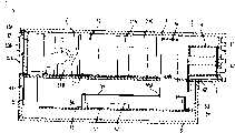
图3是图1的电子装置的内部透视图;3 is an internal perspective view of the electronic device of FIG. 1;
图4是表示图1的电子装置的后表面的透视图;4 is a perspective view showing the rear surface of the electronic device of FIG. 1;
图5是沿图3的5-5线取的截面图;Fig. 5 is a sectional view taken along line 5-5 of Fig. 3;
图6是图1所示的电子装置的主板的简图;Fig. 6 is a schematic diagram of the motherboard of the electronic device shown in Fig. 1;
图7是沿图6的7-7线取的截面图;Fig. 7 is a sectional view taken along line 7-7 of Fig. 6;
图8是沿图6的8-8线取的截面图。Fig. 8 is a cross-sectional view taken along line 8-8 of Fig. 6 .
优选实施方案的详细说明Detailed Description of the Preferred Embodiment
下面是本发明的目前想到的最好模式的详细说明。这种说明不用于在限定意义上理解,而只是作为例子用于说明本发明,通过参考下面的说明和附图,本领域技术人员可以得知本发明的优点和结构。在所有的附图中,相同的标号表示相同或相似部件。The following is a detailed description of the best presently contemplated mode of the invention. This description is not intended to be understood in a limiting sense, but is used as an example to illustrate the present invention. By referring to the following description and drawings, those skilled in the art can understand the advantages and structure of the present invention. Throughout the drawings, the same reference numerals designate the same or similar parts.
图1-5表示电子装置1,其是一种按照本发明的实施方案的娱乐装置。例如,娱乐装置1读取记录在光盘或其它介质上的游戏程序等,并按照来自用户(玩游戏者)指令执行。装置1包括安放在机壳3内的主体2。机壳3具有中心底盘4,其中提供有装置主体2,机壳3还具有上壳体5和下壳体6,其平面图呈方形,正视图大致呈L形。机壳3在使用时可以处于垂直方位和水平方位,并且其具有围绕中心底盘4不对称的结构(见简图2和图5),下壳体6的宽度和深度小于上壳体5的宽度和深度,下壳体6的容积小于上壳体5的容积。1-5 show an electronic device 1, which is an entertainment device according to an embodiment of the present invention. For example, the entertainment device 1 reads a game program or the like recorded on an optical disc or other medium, and executes it according to an instruction from a user (game player). The device 1 comprises a body 2 housed in a casing 3 . The cabinet 3 has a central chassis 4 in which the device main body 2 is provided, and an
在上壳体5的右上侧提供有光盘装置11,其控制CD-ROM,DVD-ROM或其类似物的操作,并具有托架11B。在光盘托架11B的右侧,在顶部和底部,设置有电源开关16和用于使光盘托架11B插入上壳体5并从上壳体5退出的托架操作开关17。电源开关16具有红LED 71和绿LED 72,它们显示所述装置1的电源的状态,并统一规定只有一个或另一个发光。托架操作开关17具有蓝色LED 73,其显示光盘装置11的操作状态。在上壳体5的左前方有两个槽18,每个槽的顶部有存储卡插入装置61而底部有控制器连接装置62。每个存储卡插入装置61具有由遮挡板61B覆盖的孔61A,以便保护由其内部提供的连接端子,同时控制器连接装置62具有用于连接控制器的插入孔62A。插入孔62A的形状和插入孔61A的形状不同,这样防止外部辅助存储装置误插入插入孔62A中(并且反之亦然)。On the upper right side of the
在下壳体6的左前方有通风孔6A、数据传递端子19和两个外部设备连接端子20。数据传递端子19符合IEEE 1394标准,可用于连接数字照相机、视频盘等。两个外部设备连接端子20符合USB标准,可以和键盘、鼠标或其类似物相连。On the left front of the
如图4所示,中心底盘4具有后表面41,其盖住机壳3的后表面,因而形成装置1的后表面,中心底盘4还具有板状的中间搁板42。后表面41分别由上后表面43和下后表面44构成,它们大致呈矩形,并且具有足够的长度,以便分别遮挡上下壳体5和6的部分。在上后表面43的右末端附近形成的矩形缺口43A具有AC入口32A和主电源开关32B。在下后表面44的右末端附近,缺口43A下方,露出视频-音频输出端子21,用于输出视频信号和音频信号等,还有光输出端子22,它向外部装置输出数字信号。在下后表面44的左末端附近,露出PCMCIA槽23,其中可插入各种卡型的符合PCMCIA标准的外围装置,这些装置通过按下取出按钮23A取出。此外,大约在后表面41的中心,提供有排气出口41A,通过该排气出口排出装置1内部的空气。中间搁板42具有和上壳体5基本相同的宽度和深度,并且其与上后表面43和下后表面44的接口部分成直角。在相应于排气出口41A的中间搁板42的部分中形成有一个缺口(未示出),用于放置排气风扇15。As shown in FIG. 4 , the central chassis 4 has a
如图3和图5所示,装置主体2具有光盘装置11、电源单元12和主板13,在主板上安装有计算处理单元。光盘装置11和电源单元12被设置在中心底盘4的中间搁板42上,主板13被设置在由中间搁板42和下壳体6形成的空间内。电源单元12具有电源电路板31,其被安装在中间搁板42上,还具有电源装置32,由外部电源向其输入电源。电源装置32具有上述的AC入口32A和主电源开关32B,并通过连接器31B和电源电路板31相连。即,来自外部电源的电源通过打开主电源开关32B通过AC入口32A供给电源电路板31。电源电路板31大约为中间搁板42的平面面积的一半,由外部电源提供的AC电源由电容、线圈、变压器以及构成所述电源电路板31的其它电路元件31A转换成DC电源和预定的电压。在电源电路板31上提供有一个L型的导向板31C,用于沿预定方向通过在下壳体6中形成的开口6A引入冷空气。这样,电源单元12向光盘装置11和主板13等提供由电源电路板31获得的电源。As shown in FIG. 3 and FIG. 5 , the device main body 2 has an
在所述排气出口41A的一侧连接有排气扇15,其也由来自电源单元12的电源驱动。在排气出口41A的一侧和在相对侧上的开口6A附近设置有下述的矩形散热器54和槽18,所述散热器是一个热辐射装置。On one side of the exhaust outlet 41A is connected an
主板13具有由CPU 51及其外围装置等组成的控制系统(未示出),包括根据来自CPU 51的信号形成输出图像的图像处理单元75的图形系统(未示出),包括用于产生音乐和声音效果等的音频处理单元的声音系统(未示出),以及作为电源控制装置控制由电源单元12向所述控制系统、图形系统和声音系统等供电的微处理器单元(未示出)。CPU 51通过执行(计算处理)操作系统在整体上控制装置1。图形系统具有图像处理单元75,其在来自CPU 51的绘画指令下提供图像,还具有帧缓冲器,在其中存储由所述图像处理单元75提供的图像。
在CPU 51和图像处理单元75的上表面上提供有优选由高导热率的铝制成的导热部件52,其骑跨着所述CPU 51和图像处理单元75。在导热部件52的上表面提供有以预定间隔隔开的多个T形销52A。Provided on the upper surfaces of the
如图6所示,导热部件52呈矩形板的形状,其从CPU 51的一端到图像处理单元75的一端的宽度为W和从CPU 51的另一端到邻近散热器54的一端的长度为L。因而,CPU 51和图像处理单元75的上表面被导热部件52覆盖。在导热部件52和CPU 51以及图像处理单元75之间插入柔性板80,如图7和图8所示。柔性板80最好呈矩形板的形状,其具有盖住CPU 51和图像处理单元75上表面的尺寸,因而骑跨所述CPU 51和图像处理单元75。柔性板80的厚度优选是0.2-5mm,最好是大约1mm。As shown in FIG. 6, the
柔性板80最好由硅树脂胶、吸收由CPU 51和图像处理单元75产生的电磁辐射的金属氧化物磁颗粒以及具有氧化铝的混合物组成,所述混合物是一种金属氧化物,其是一种能够促进CPU 51和图像处理单元75的热辐射的传热垫片的金属氧化物。所述硅树脂胶最好具有高于其它有机合成树脂的热阻温度,使得所述柔性板能够耐受由计算处理单元产生的热量。在公开的实施方案中,金属氧化物磁颗粒是Mn-Zn铁氧体,其平均颗粒直径范围为1-50Fm,也可以使用其它的金属氧化物磁颗粒,例如Ni-Zn铁氧体,Mn-Zn和Ni-Zn的混合物或其类似物。柔性板80的两侧最好是粘合剂,并以使得柔性板分别粘结在导热部件52和CPU 51以及图像处理单元75上的方式提供,这可以改善柔性板80吸收电磁辐射和热量的能力。The
CPU 51、图像处理单元75、柔性板80和导热部件52由一个最好由金属制成的单一屏蔽部件53覆盖,最好是屏蔽部件53的尺寸能够盖住计算处理单元和图像处理单元。在电子装置使用的处理单元当中计算处理单元和图像处理单元最好被分成以最高速度操作的并产生最大热量和电磁辐射的部分,用这种方式,即使提供产生很多热量和电磁辐射的多个处理单元,比起为每个处理单元提供屏蔽部件所述电子装置更容易制造,也更少产生故障。
屏蔽部件53还包括和导热部件52的上表面接触的平的屏蔽部分55,以及具有L形截面,并从平的屏蔽部分55的两端向主板13的上表面延伸的侧面屏蔽部分。在平的屏蔽部分55上形成的孔55B位于在导热部件52的上表面提供的销52A相对应的位置上。因而,通过在孔55A中插入销55B并使销52A的上部对着平的屏蔽部分55的上表面伸出,平的屏蔽部分55便被固定在导热部件52上。侧屏蔽部分56有从屏蔽部分55的端部向下延伸的垂直部分56A,以及从垂直部分56A的端部水平向外延伸的水平部分56B,并且其下表面和主板13的上表面接触。通过使用柔性板80和屏蔽部件53,由CPU 51和图像处理单元75发出的电磁辐射可被可靠而完全地切断,可以容易地阻止由电源单元12等产生的噪声或其它干扰进入CPU 51等装置中,因而可以可靠地维持CPU 51和图像处理单元75的稳定运行。此外,柔性板80使快速吸收由CPU 51和图像处理单元75产生的热量成为可能。The shielding
最好在导热部件52上提供温度传感器(未示出),由其检测CPU51和图像处理单元75的温度。温度传感器具有检测导热部件52温度的传感器部分和用于把检测的温度转换成温度检测信号的信号转换部分,其输出和微处理器单元相连。微处理器单元根据来自所述温度传感器的温度异常检测信号控制由电源单元12向主板13的CPU 51和图像处理单元75提供的电源。It is preferable to provide a temperature sensor (not shown) on the
在导热部件52的端部的上表面,也就是屏蔽部件53的外侧提供了热消散装置形式的矩形散热器54。即,散热器54跨过导热部件52以骑跨CPU 51和图像处理单元75。散热器54从导热部件52的上表面向上壳体5的顶部附近延伸。因而,如图5所示,在中间搁板42和平的屏蔽部分55中相应于散热器54的位置分别形成开口42B和55A。因而,由CPU 51和图像处理单元75产生的热量快速地被柔性板80吸收,通过所述柔性板80和导热部件52传递给位于屏蔽部件53的外侧上的散热器54,并从散热器54向外消散。On the upper surface of the end portion of the
通过使用屏蔽部件53和柔性板80,由CPU 51和图像处理单元75产生的电磁辐射可以被可靠而完全地阻断。此外,因为柔性板80含有氧化铝,由CPU 51和图像处理单元75产生的热量被所述柔性板80快速吸收,并消散到屏蔽部件53的外部,因而阻止CPU 51和图像处理单元75的温度增加。而且,因为柔性板80设置为骑跨着CPU 51和图像处理单元75,所以和把柔性板单独设置在CPU 51以及图像处理单元75上的情况相比,柔性板80的放置操作可以更容易地进行。By using the
虽然针对上述的实施方案对本发明进行了详细的说明,但是本发明不限于上述的实施方案,而是包括可以实现本发明目的的其它实施方案,包括但不限于下述的改型。Although the present invention has been described in detail with respect to the above-mentioned embodiments, the present invention is not limited to the above-mentioned embodiments, but includes other embodiments that can achieve the purpose of the present invention, including but not limited to the following modifications.
例如,在上述的实施方案中,柔性板80设置成骑跨着CPU 51和图像处理单元75。不过,柔性板80可以制成合适的尺寸分别设置在CPU 51和图像处理单元75上,并且这可以按照实施情况合理地确定。此外,虽然屏蔽部件53最好制成足以盖住CPU 51和图像处理单元75的尺寸,其也可以制成足以分别盖住CPU 51和图像处理单元75的尺寸。此外,虽然柔性板80最好含有铝的氧化物,但是其可以含有金属氧化物例如氧化镁,氧化锌,氧化钛,氮化铝,氮化硼,氮化硅或碳化硅等,或者只要其具有另一种能够促进CPU 51和图像处理单元75的散热的介质,也可以不含有这些物质。For example, in the above-described embodiments, the
虽然针对几个所述的实施方案对本发明进行了详细说明,但是本发明并不限于所述的任何这种细节或实施方案或任何特殊的实施方案,本发明的范围只结合所附权利要求书提供在现有技术看来最广的对权利要求书的可能解释,从而有效地包括本发明想要保护的范围。While the invention has been described in detail with respect to several described embodiments, the invention is not limited to any such detail or embodiment described or to any particular embodiment, the scope of the invention being limited only by reference to the appended claims Provide the broadest possible interpretation of the claims in the view of the prior art, so as to effectively cover the intended protection scope of the present invention.
Claims (16)
Applications Claiming Priority (3)
| Application Number | Priority Date | Filing Date | Title |
|---|---|---|---|
| JP2000058729 | 2000-03-03 | ||
| JP58729/00 | 2000-03-03 | ||
| JP58729/2000 | 2000-03-03 |
Publications (2)
| Publication Number | Publication Date |
|---|---|
| CN1366800Atrue CN1366800A (en) | 2002-08-28 |
| CN1197446C CN1197446C (en) | 2005-04-13 |
Family
ID=18579278
Family Applications (1)
| Application Number | Title | Priority Date | Filing Date |
|---|---|---|---|
| CNB018010377AExpired - LifetimeCN1197446C (en) | 2000-03-03 | 2001-03-01 | Electronic device and shield |
Country Status (14)
| Country | Link |
|---|---|
| US (1) | US6498733B2 (en) |
| EP (1) | EP1181853B1 (en) |
| KR (1) | KR100790204B1 (en) |
| CN (1) | CN1197446C (en) |
| AT (1) | ATE361656T1 (en) |
| AU (1) | AU3601701A (en) |
| BR (1) | BR0105555A (en) |
| CA (1) | CA2370716A1 (en) |
| DE (1) | DE60128191T2 (en) |
| HK (1) | HK1040474A1 (en) |
| MX (1) | MXPA01011118A (en) |
| NZ (1) | NZ515116A (en) |
| RU (1) | RU2001132865A (en) |
| WO (1) | WO2001065901A2 (en) |
Cited By (1)
| Publication number | Priority date | Publication date | Assignee | Title |
|---|---|---|---|---|
| CN102412854A (en)* | 2006-08-18 | 2012-04-11 | 德尔菲技术公司 | Lightweight audio system for automotive applications and method |
Families Citing this family (15)
| Publication number | Priority date | Publication date | Assignee | Title |
|---|---|---|---|---|
| JP4048435B2 (en) | 2003-10-23 | 2008-02-20 | ソニー株式会社 | Electronics |
| KR100652621B1 (en)* | 2003-11-21 | 2006-12-06 | 엘지전자 주식회사 | Heat dissipation device of portable terminal |
| JP2005249909A (en)* | 2004-03-02 | 2005-09-15 | Pioneer Electronic Corp | Shielding case of image display apparatus and image display apparatus |
| TWI264993B (en)* | 2005-03-08 | 2006-10-21 | Asustek Comp Inc | Shielding structure |
| US9237685B2 (en) | 2006-08-18 | 2016-01-12 | Delphi Technologies, Inc. | Lightweight audio system for automotive applications and method |
| US8264856B2 (en) | 2006-08-18 | 2012-09-11 | Delphi Technologies, Inc. | Lightweight audio system for automotive: applications and method |
| JP4914678B2 (en)* | 2006-08-31 | 2012-04-11 | 任天堂株式会社 | Electronics |
| US9072169B1 (en)* | 2010-07-13 | 2015-06-30 | Cascodium Inc. | Pulse generator and systems and methods for using same |
| JP5634644B2 (en)* | 2012-08-03 | 2014-12-03 | 三菱電機株式会社 | Chassis assembly structure |
| JP5619966B2 (en)* | 2012-10-11 | 2014-11-05 | アサステック・コンピューター・インコーポレイテッドAsustek Computer Inc. | Heat dissipation structure |
| US9781819B2 (en)* | 2015-07-31 | 2017-10-03 | Laird Technologies, Inc. | Multifunctional components for electronic devices and related methods of providing thermal management and board level shielding |
| WO2017169228A1 (en)* | 2016-03-28 | 2017-10-05 | パナソニックIpマネジメント株式会社 | Electrical connection structure |
| CN111757660B (en)* | 2020-07-15 | 2022-06-21 | 太原理工大学 | A non-enclosed electromagnetic shielding room |
| EP4366475A4 (en)* | 2021-10-26 | 2025-01-22 | Samsung Electronics Co., Ltd. | PRINTED CIRCUIT BOARD AND ELECTRONIC DEVICE THEREOF |
| TWM649139U (en)* | 2023-07-14 | 2023-12-01 | 正文科技股份有限公司 | Communication assembly and heat dissipation and shielding module thereof |
Family Cites Families (19)
| Publication number | Priority date | Publication date | Assignee | Title |
|---|---|---|---|---|
| FR2454251B1 (en) | 1979-04-13 | 1987-06-12 | Klein Siegfried | ARMORED CIRCUIT WITHOUT LEAKS OF INTERFERENCE ELECTROMAGNETIC WAVES |
| EP0360971A3 (en)* | 1988-08-31 | 1991-07-17 | Mitsui Mining & Smelting Co., Ltd. | Mounting substrate and its production method, and printed wiring board having connector function and its connection method |
| US5060114A (en)* | 1990-06-06 | 1991-10-22 | Zenith Electronics Corporation | Conformable pad with thermally conductive additive for heat dissipation |
| US5366664A (en) | 1992-05-04 | 1994-11-22 | The Penn State Research Foundation | Electromagnetic shielding materials |
| JPH08116195A (en)* | 1994-10-14 | 1996-05-07 | Matsushita Electric Ind Co Ltd | Circuit unit shield device |
| JPH08279689A (en)* | 1995-04-10 | 1996-10-22 | Matsushita Electric Ind Co Ltd | Shielding device for semiconductor devices |
| US5981043A (en)* | 1996-04-25 | 1999-11-09 | Tatsuta Electric Wire And Cable Co., Ltd | Electroconductive coating composition, a printed circuit board fabricated by using it and a flexible printed circuit assembly with electromagnetic shield |
| TW345667B (en)* | 1996-09-09 | 1998-11-21 | Tokiin Corp | High thermal conductivity composite magnetic substance |
| JPH10224061A (en)* | 1997-02-10 | 1998-08-21 | Matsushita Electric Ind Co Ltd | Heat sink unit and electronic equipment |
| JPH10322085A (en) | 1997-03-14 | 1998-12-04 | Daido Steel Co Ltd | Shielding sheet and manufacturing method thereof |
| US5880930A (en)* | 1997-06-18 | 1999-03-09 | Silicon Graphics, Inc. | Electromagnetic interference shielding enclosure and heat sink with compression coupling mechanism |
| GB2327537B (en)* | 1997-07-18 | 2002-05-22 | Nokia Mobile Phones Ltd | Electronic device |
| US6049469A (en)* | 1997-08-20 | 2000-04-11 | Dell Usa, L.P. | Combination electromagnetic shield and heat spreader |
| US6350951B1 (en)* | 1997-12-29 | 2002-02-26 | Intel Corporation | Electric shielding of on-board devices |
| JP3969618B2 (en) | 1998-03-23 | 2007-09-05 | 富士高分子工業株式会社 | Electromagnetic wave absorbing heat conductive silicone gel molded sheet and method for producing the same |
| JP3032505B1 (en)* | 1998-10-19 | 2000-04-17 | 北川工業株式会社 | heatsink |
| US6208516B1 (en)* | 1999-05-11 | 2001-03-27 | Apple Computer, Inc. | Electromagnetic interference shield and gap filler for a circuit board |
| US6219239B1 (en)* | 1999-05-26 | 2001-04-17 | Hewlett-Packard Company | EMI reduction device and assembly |
| US6195267B1 (en)* | 1999-06-23 | 2001-02-27 | Ericsson Inc. | Gel structure for combined EMI shielding and thermal control of microelectronic assemblies |
- 2001
- 2001-03-01ATAT01908186Tpatent/ATE361656T1/ennot_activeIP Right Cessation
- 2001-03-01EPEP01908186Apatent/EP1181853B1/ennot_activeExpired - Lifetime
- 2001-03-01WOPCT/JP2001/001555patent/WO2001065901A2/enactiveIP Right Grant
- 2001-03-01CACA002370716Apatent/CA2370716A1/ennot_activeAbandoned
- 2001-03-01CNCNB018010377Apatent/CN1197446C/ennot_activeExpired - Lifetime
- 2001-03-01NZNZ515116Apatent/NZ515116A/ennot_activeIP Right Cessation
- 2001-03-01KRKR1020017014022Apatent/KR100790204B1/ennot_activeExpired - Fee Related
- 2001-03-01MXMXPA01011118Apatent/MXPA01011118A/enunknown
- 2001-03-01RURU2001132865/09Apatent/RU2001132865A/ennot_activeApplication Discontinuation
- 2001-03-01DEDE60128191Tpatent/DE60128191T2/ennot_activeExpired - Lifetime
- 2001-03-01USUS09/797,421patent/US6498733B2/ennot_activeExpired - Lifetime
- 2001-03-01BRBR0105555-0Apatent/BR0105555A/ennot_activeApplication Discontinuation
- 2001-03-01AUAU36017/01Apatent/AU3601701A/ennot_activeAbandoned
- 2001-03-01HKHK02101748.1Apatent/HK1040474A1/enunknown
Cited By (5)
| Publication number | Priority date | Publication date | Assignee | Title |
|---|---|---|---|---|
| CN102412854A (en)* | 2006-08-18 | 2012-04-11 | 德尔菲技术公司 | Lightweight audio system for automotive applications and method |
| CN102412854B (en)* | 2006-08-18 | 2014-03-05 | 德尔菲技术公司 | Automotive audio system |
| CN102412853B (en)* | 2006-08-18 | 2014-08-27 | 德尔菲技术公司 | Audio system for vehicle |
| CN102412851B (en)* | 2006-08-18 | 2014-09-24 | 德尔菲技术公司 | Lightweight audio system for automotive applications and method |
| CN102510288B (en)* | 2006-08-18 | 2014-10-22 | 德尔菲技术公司 | Audio system for vehicle |
Also Published As
| Publication number | Publication date |
|---|---|
| DE60128191D1 (en) | 2007-06-14 |
| EP1181853A1 (en) | 2002-02-27 |
| ATE361656T1 (en) | 2007-05-15 |
| BR0105555A (en) | 2002-03-19 |
| EP1181853B1 (en) | 2007-05-02 |
| MXPA01011118A (en) | 2002-06-04 |
| HK1040474A1 (en) | 2002-06-07 |
| NZ515116A (en) | 2002-12-20 |
| US20010019477A1 (en) | 2001-09-06 |
| KR20020007394A (en) | 2002-01-26 |
| AU3601701A (en) | 2001-09-12 |
| KR100790204B1 (en) | 2007-12-31 |
| WO2001065901A3 (en) | 2002-03-14 |
| DE60128191T2 (en) | 2007-12-27 |
| CN1197446C (en) | 2005-04-13 |
| WO2001065901A2 (en) | 2001-09-07 |
| CA2370716A1 (en) | 2001-09-07 |
| RU2001132865A (en) | 2003-09-10 |
| US6498733B2 (en) | 2002-12-24 |
Similar Documents
| Publication | Publication Date | Title |
|---|---|---|
| CN1366800A (en) | Electronic device and shield | |
| US6565444B2 (en) | Electronic equipment and television game machine having heat radiation structure | |
| US8014146B2 (en) | Computer system with airflow blocking plate | |
| JP4686427B2 (en) | Electronics | |
| JPH08264980A (en) | Portable electronic devices | |
| US8564948B2 (en) | Electronic device | |
| CN103262675A (en) | Set-top box having dissipating thermal loads | |
| US8917503B2 (en) | Heat dissipation device | |
| TW201146104A (en) | Electronic assembly and casing therefor | |
| US7254035B2 (en) | Circuit substrate unit and electronic equipment | |
| US6661665B2 (en) | Method and apparatus for removing heat from an electronic device | |
| US20130033816A1 (en) | Computer with heat dissipation system | |
| US6867985B2 (en) | Computer system with noiseless cooling | |
| JP2001077568A (en) | Electronic equipment | |
| US20070248460A1 (en) | Magnetic-attaching structure for a fan | |
| CN103037664A (en) | Radiating device and electronic device using same | |
| US20070030649A1 (en) | Electronic device | |
| US20080239664A1 (en) | Heat dissipating system for computer | |
| JP2001320192A (en) | Electronic apparatus | |
| EP1785807B1 (en) | Cooling of a small electronic device with a USB connector | |
| TWM655511U (en) | electronic device | |
| US20060023418A1 (en) | Portable drive system | |
| JP2005309738A (en) | Electronic equipment | |
| TWM445206U (en) | Heat dissipating system of computer mainframe | |
| KR20040056369A (en) | electromagnetic shielding plate and apparatus for computer cooling using thereof |
Legal Events
| Date | Code | Title | Description |
|---|---|---|---|
| C06 | Publication | ||
| PB01 | Publication | ||
| C10 | Entry into substantive examination | ||
| SE01 | Entry into force of request for substantive examination | ||
| C14 | Grant of patent or utility model | ||
| GR01 | Patent grant | ||
| CX01 | Expiry of patent term | ||
| CX01 | Expiry of patent term | Granted publication date:20050413 |