CN1365016A - Wearable display system - Google Patents
Wearable display systemDownload PDFInfo
- Publication number
- CN1365016A CN1365016ACN01143633ACN01143633ACN1365016ACN 1365016 ACN1365016 ACN 1365016ACN 01143633 ACN01143633 ACN 01143633ACN 01143633 ACN01143633 ACN 01143633ACN 1365016 ACN1365016 ACN 1365016A
- Authority
- CN
- China
- Prior art keywords
- grating
- angle
- waveguide
- signal
- incident
- Prior art date
- Legal status (The legal status is an assumption and is not a legal conclusion. Google has not performed a legal analysis and makes no representation as to the accuracy of the status listed.)
- Granted
Links
Images


Classifications
- G—PHYSICS
- G02—OPTICS
- G02B—OPTICAL ELEMENTS, SYSTEMS OR APPARATUS
- G02B27/00—Optical systems or apparatus not provided for by any of the groups G02B1/00 - G02B26/00, G02B30/00
- G02B27/01—Head-up displays
- G02B27/017—Head mounted
- G02B27/0172—Head mounted characterised by optical features
- G—PHYSICS
- G02—OPTICS
- G02B—OPTICAL ELEMENTS, SYSTEMS OR APPARATUS
- G02B27/00—Optical systems or apparatus not provided for by any of the groups G02B1/00 - G02B26/00, G02B30/00
- G02B27/42—Diffraction optics, i.e. systems including a diffractive element being designed for providing a diffractive effect
- G02B27/4272—Diffraction optics, i.e. systems including a diffractive element being designed for providing a diffractive effect having plural diffractive elements positioned sequentially along the optical path
- G—PHYSICS
- G02—OPTICS
- G02B—OPTICAL ELEMENTS, SYSTEMS OR APPARATUS
- G02B27/00—Optical systems or apparatus not provided for by any of the groups G02B1/00 - G02B26/00, G02B30/00
- G02B27/01—Head-up displays
- G02B27/0101—Head-up displays characterised by optical features
- G02B2027/0132—Head-up displays characterised by optical features comprising binocular systems
- G02B2027/0136—Head-up displays characterised by optical features comprising binocular systems with a single image source for both eyes
- G—PHYSICS
- G02—OPTICS
- G02B—OPTICAL ELEMENTS, SYSTEMS OR APPARATUS
- G02B27/00—Optical systems or apparatus not provided for by any of the groups G02B1/00 - G02B26/00, G02B30/00
- G02B27/01—Head-up displays
- G02B27/017—Head mounted
- G02B27/0172—Head mounted characterised by optical features
- G02B2027/0174—Head mounted characterised by optical features holographic
- G—PHYSICS
- G02—OPTICS
- G02B—OPTICAL ELEMENTS, SYSTEMS OR APPARATUS
- G02B6/00—Light guides; Structural details of arrangements comprising light guides and other optical elements, e.g. couplings
- G02B6/0001—Light guides; Structural details of arrangements comprising light guides and other optical elements, e.g. couplings specially adapted for lighting devices or systems
- G02B6/0011—Light guides; Structural details of arrangements comprising light guides and other optical elements, e.g. couplings specially adapted for lighting devices or systems the light guides being planar or of plate-like form
- G02B6/0013—Means for improving the coupling-in of light from the light source into the light guide
- G02B6/0015—Means for improving the coupling-in of light from the light source into the light guide provided on the surface of the light guide or in the bulk of it
- G02B6/0016—Grooves, prisms, gratings, scattering particles or rough surfaces
- G—PHYSICS
- G02—OPTICS
- G02B—OPTICAL ELEMENTS, SYSTEMS OR APPARATUS
- G02B6/00—Light guides; Structural details of arrangements comprising light guides and other optical elements, e.g. couplings
- G02B6/0001—Light guides; Structural details of arrangements comprising light guides and other optical elements, e.g. couplings specially adapted for lighting devices or systems
- G02B6/0011—Light guides; Structural details of arrangements comprising light guides and other optical elements, e.g. couplings specially adapted for lighting devices or systems the light guides being planar or of plate-like form
- G02B6/0033—Means for improving the coupling-out of light from the light guide
- G02B6/0035—Means for improving the coupling-out of light from the light guide provided on the surface of the light guide or in the bulk of it
- G02B6/0038—Linear indentations or grooves, e.g. arc-shaped grooves or meandering grooves, extending over the full length or width of the light guide
Landscapes
- Physics & Mathematics (AREA)
- General Physics & Mathematics (AREA)
- Optics & Photonics (AREA)
- Lenses (AREA)
- Diffracting Gratings Or Hologram Optical Elements (AREA)
- Eyeglasses (AREA)
- Optical Elements Other Than Lenses (AREA)
Abstract
Translated fromChinese
Description
Translated fromChinese技术领域technical field
本发明涉及个人显示系统,特别是能够通过眼镜型或风镜型光学器件透射显示信号以在用户的眼附近的地方显示的可佩戴的显示系统。The present invention relates to personal display systems, in particular wearable display systems capable of transmitting display signals through eyeglass or goggle type optics for display in the vicinity of the user's eyes.
背景技术Background technique
用在军事、医学或个人娱乐的传统光显示系统——通常被称为头戴式显示器(HMD)——已经被设计用来供用户通过眼镜型、风镜型或头盔型可佩戴器件来观看视频信号。这些个人显示系统使得用户可以在从一处到一处移动时接收视频信息。图1示出了HMD的外形的示例。参见图1,HMD由普通眼镜100和附在眼镜100中心的图像驱动单元110构成。驱动单元110体积大、重量高而且外形不美观。图像驱动单元110的大体积和高重量的原因在于构成该单元的多个光元件。Traditional optical display systems used in military, medical, or personal entertainment—often referred to as head-mounted displays (HMDs)—have been designed to allow users to view video through glasses, goggles, or helmet-type wearables Signal. These personal display systems allow users to receive video information while moving from place to place. FIG. 1 shows an example of the appearance of an HMD. Referring to FIG. 1 , the HMD is composed of
图2示出了一般HMD的结构。在图2中,HMD包括一个图像驱动单元200、一个显示面板210和一个光学系统220。图像驱动单元200存储从诸如个人计算机或视频器件(未示出)的外部来源接收的信号并处理该接收的信号以在诸如液晶显示器(LCD)面板的显示面板210上显示它。光学系统220使得显示在显示面板210上的该信号通过图像放大光学系统对用户的眼睛看起来是合适的虚像。HMD可以进一步包括其他头戴式器件或线缆用于从外部来源接收信号。Fig. 2 shows the structure of a general HMD. In FIG. 2 , the HMD includes an
图3示出了图2的一般HMD的光学系统220的一般结构。传统的光学系统220包括准直透镜300、X棱镜310、聚焦透镜320、折叠式反射镜330和目镜透镜(或放大透镜)340。准直透镜300对从显示面板等发出的光(信号)准直。X棱镜310将在左右方向从准直透镜300接收的光变向。聚焦透镜320被单独地放在X棱镜310的左右以聚焦由X棱镜310变向的准直光。折叠式反射镜330将由聚焦透镜320聚焦的光反射到用户眼睛。目镜透镜(或放大透镜)340使得穿过上述光学元件的小信号出现到用户的眼睛中。此时,如果传播通过光学系统220的光是多色的,则必须使用去除色差的透镜作为目镜透镜340。FIG. 3 shows a general structure of an optical system 220 of the general HMD of FIG. 2 . The conventional optical system 220 includes a collimating lens 300 , an X prism 310 , a focusing lens 320 , a folding mirror 330 and an eyepiece lens (or magnifying lens) 340 . The collimator lens 300 collimates light (signal) emitted from a display panel or the like. The X prism 310 redirects light received from the collimator lens 300 in left and right directions. Focusing lenses 320 are separately placed on the left and right of the X prism 310 to focus the collimated light redirected by the X prism 310 . The folding mirror 330 reflects the light focused by the focusing lens 320 to the user's eyes. The eyepiece lens (or magnifying lens) 340 causes the small signal passing through the aforementioned optical elements to appear into the user's eye. At this time, if light propagating through the optical system 220 is polychromatic, a lens that removes chromatic aberration must be used as the eyepiece lens 340 .
在一般的HMD可佩戴显示系统中,光学系统使用几个精确设计的光学元件,如准直透镜、X棱镜、聚焦透镜、折叠式透镜、目镜透镜等,如上所述。因此,很难制造一般的HMD可佩戴显示系统,即,这需要很多精力和时间。即使透镜和元件被设计得很精密,也可能发生将透镜和器件对准的附加困难。而且,必须额外设计专用的目镜透镜来消除彩色信号的色差。因此,一般的HMD可佩戴显示系统制造起来太昂贵。另外传统的光学系统由于使用多个光学器件而体积大、重量高,因此对于用户来说佩戴HMD不方便。In a general HMD wearable display system, the optical system uses several precisely designed optical components, such as collimating lens, X prism, focusing lens, folding lens, eyepiece lens, etc., as mentioned above. Therefore, it is difficult to manufacture a general HMD wearable display system, ie, it requires much effort and time. Even if the lenses and components are carefully designed, additional difficulties in aligning the lenses and components may occur. Moreover, a special eyepiece lens must be additionally designed to eliminate the chromatic aberration of the color signal. Therefore, typical HMD wearable display systems are too expensive to manufacture. In addition, the conventional optical system is bulky and heavy due to the use of multiple optical devices, and thus it is inconvenient for the user to wear the HMD.
发明内容Contents of the invention
为了解决上述问题,本发明的一个目的是提供一种可佩戴的显示系统,它易于制造、利用光栅消除色差和实现三维图像。In order to solve the above-mentioned problems, an object of the present invention is to provide a wearable display system that is easy to manufacture, eliminates chromatic aberration using a grating, and realizes a three-dimensional image.
因此,为了达到上述目的,提供了一种可佩戴的显示系统,它具有至少一个显示面板,用于输出至少一种以预定方式处理的信号,该系统包括:至少一个波导,用于引导从至少一个显示面板输出的至少一个信号的传播;多个光栅,用于衍射通过至少一个波导传播的至少一个信号;至少一个放大透镜,用于放大由至少一个光栅衍射的至少一个信号。Therefore, in order to achieve the above objects, a wearable display system is provided, which has at least one display panel for outputting at least one signal processed in a predetermined manner, the system comprising: at least one waveguide for guiding from at least propagation of at least one signal output by a display panel; a plurality of gratings for diffracting the at least one signal propagating through the at least one waveguide; at least one magnifying lens for amplifying the at least one signal diffracted by the at least one grating.
最好有多个光栅,包括:至少一个第一光栅,用于衍射从至少一个显示面板输出的至少一个信号,以便至少一个信号传播通过至少一个波导;至少一个第二光栅,用于衍射在被至少一个第一光栅衍射后传播穿过至少一个波导的至少一个信号。Preferably there are a plurality of gratings, comprising: at least one first grating for diffracting at least one signal output from the at least one display panel so that the at least one signal propagates through the at least one waveguide; at least one second grating for diffracting At least one first grating diffracts at least one signal propagating through the at least one waveguide.
最好有多个光栅,包括:至少一个第一光栅,用于以预定反射角反射从至少一个显示面板输出并以预定入射角入射在至少一个第一光栅上的至少一个信号;至少一个第二光栅,用于以与至少一个第一光栅的预定入射角相同的角度反射传播穿过至少一个波导并以与至少一个第一光栅的预定反射角相同的角度入射在至少一个第二光栅上的至少一个信号。Preferably there are a plurality of gratings, including: at least one first grating for reflecting at least one signal output from at least one display panel at a predetermined angle of reflection and incident on at least one first grating at a predetermined angle of incidence; at least one second grating a grating for reflecting at least one waveguide propagating through the at least one waveguide and incident on the at least one second grating at the same angle as the predetermined angle of incidence of the at least one first grating a signal.
最好有多个光栅,包括:至少一个第一光栅,用于以预定透射角透射从至少一个显示面板输出并以预定入射角入射在至少一个第一光栅上的至少一个信号,以传播通过至少一个波导;至少一个第二光栅,用于以与至少一个第一光栅的预定入射角相同的角度透射传播穿过至少一个波导并以与至少一个第一光栅的预定透射角相同的角度入射在至少一个第二光栅上的至少一个信号。Preferably there are a plurality of gratings, including: at least one first grating for transmitting at least one signal output from at least one display panel at a predetermined transmission angle and incident on the at least one first grating at a predetermined angle of incidence to propagate through at least one of the first gratings a waveguide; at least one second grating for propagating through the at least one waveguide with transmission at the same angle as the predetermined angle of incidence of the at least one first grating and incident at the same angle as the predetermined angle of incidence of the at least one first grating At least one signal on a second grating.
最好有多个光栅,包括:至少一个第一光栅,用于以预定反射角反射从至少一个显示面板输出并以预定入射角入射在至少一个第一光栅上的至少一个信号;至少一个第二光栅,用于以与至少一个第一光栅的预定入射角相同的角度透射传播穿过至少一个波导并以与至少一个第一光栅的预定反射角相同的角度入射在至少一个第二光栅上的至少一个信号。Preferably there are a plurality of gratings, including: at least one first grating for reflecting at least one signal output from at least one display panel at a predetermined angle of reflection and incident on at least one first grating at a predetermined angle of incidence; at least one second grating grating for transmitting at least one second grating propagating through the at least one waveguide at the same angle as the predetermined angle of incidence of the at least one first grating and incident on the at least one second grating at the same angle as the predetermined angle of reflection of the at least one first grating a signal.
最好有多个光栅,包括:至少一个第一光栅,用于以预定透射角透射从至少一个显示面板输出并以预定入射角入射在至少一个第一光栅上的至少一个信号;至少一个第二光栅,用于以与至少一个第一光栅的预定入射角相同的角度反射传播穿过至少一个波导并以与至少一个第一光栅的预定透射角相同的角度入射在至少一个第二光栅上的至少一个信号。Preferably there are a plurality of gratings, including: at least one first grating for transmitting at least one signal output from at least one display panel and incident on the at least one first grating at a predetermined angle of incidence at a predetermined transmission angle; at least one second grating a grating for reflecting at least one waveguide propagating through the at least one waveguide and incident on the at least one second grating at the same angle as the predetermined angle of incidence of the at least one first grating a signal.
最好可佩戴显示系统还包括至少一个快门,用于交替阻塞在波导中的至少一个信号,以产生一个三维图像。Preferably the wearable display system further includes at least one shutter for alternately blocking at least one signal in the waveguide to generate a three-dimensional image.
最好至少一个放大透镜是沿着至少一个波导的预定长度可移动的。Preferably at least one magnifying lens is movable along a predetermined length of at least one waveguide.
波导最好由玻璃或塑料或特别地,由丙烯基底((PMMA))构成。The waveguide preferably consists of glass or plastic or, in particular, of an acrylic substrate ((PMMA)).
最好光栅和波导被并入一个单一壳体中。Preferably the grating and waveguide are incorporated into a single housing.
最好放大透镜和波导被并入一个单一壳体中。Preferably the magnifying lens and waveguide are incorporated into a single housing.
最好光栅和放大透镜被并入一个单一壳体中。Preferably the grating and magnifying lens are incorporated into a single housing.
放大透镜最好由全息光学元件(HOE)或衍射光学元件(DOE)形成。The magnifying lens is preferably formed by a holographic optical element (HOE) or a diffractive optical element (DOE).
附图说明Description of drawings
通过参照附图详细说明优选实施例,本发明的上述目的和特点将会变得更加清楚,其中:The above objects and features of the present invention will become clearer by describing preferred embodiments with reference to the accompanying drawings, wherein:
图1是传统头戴式显示器(HMD)的外部视图;FIG. 1 is an external view of a conventional head-mounted display (HMD);
图2是一般传统HMD的示意图;FIG. 2 is a schematic diagram of a general conventional HMD;
图3图2的一般传统HMD中光学系统的示意图;FIG. 3 is a schematic diagram of the optical system in the general conventional HMD of FIG. 2;
图4A和4B示出了按照本发明的可佩戴显示系统;4A and 4B illustrate a wearable display system according to the present invention;
图5是按照本发明的可佩戴显示系统的优选实施例的示意图;5 is a schematic diagram of a preferred embodiment of a wearable display system according to the present invention;
图6图解了用于解释光栅间的共轭关系的示例;Figure 6 illustrates an example for explaining the conjugate relationship between gratings;
图7A图解了光栅的一个示例;Figure 7A illustrates an example of a grating;
图7B和7C分别图解了透射型光栅和反射型光栅;7B and 7C illustrate transmissive and reflective gratings, respectively;
图8A至8H示出了按照光栅类型和波导上的光栅布置的本发明的可佩戴显示系统的各种可能实施例;Figures 8A to 8H illustrate various possible embodiments of the wearable display system of the present invention in terms of grating types and grating arrangements on waveguides;
图9示出了按照本发明的可佩戴显示系统的另一个实施例;Figure 9 shows another embodiment of a wearable display system according to the present invention;
图10A和10B示出了按照本发明的可佩戴显示系统的其他优选实施例,其中显示面板附在波导的两边;Figures 10A and 10B show other preferred embodiments of the wearable display system according to the present invention, wherein the display panels are attached to both sides of the waveguide;
图11示出了按照本发明的可佩戴显示系统,它采用了快门来实现三维图像;Figure 11 shows a wearable display system according to the present invention, which uses a shutter to achieve a three-dimensional image;
图12A和12B图解了按照本发明的在可佩戴显示系统中控制瞳孔间的距离(IPD)的一个应用;12A and 12B illustrate an application of controlling the interpupillary distance (IPD) in a wearable display system according to the present invention;
图13示出了具有单筒结构的、按照本发明的可佩戴显示系统的优选实施例;Fig. 13 shows a preferred embodiment of a wearable display system according to the present invention with a monotube structure;
图14A和14H示出了依赖于光栅类型和波导上的光栅布置的、具有单筒结构的、按照本发明的可佩戴显示系统的各种可能实施例;Figures 14A and 14H show various possible embodiments of a wearable display system according to the invention with a monocular structure depending on the type of grating and the arrangement of the grating on the waveguide;
图15A和15B示出了具有单筒结构的、按照本发明的可佩戴显示系统的其他实施例;Figures 15A and 15B illustrate other embodiments of wearable display systems according to the present invention having a monotube structure;
图16A和16B图解了本发明中使用的通过光栅消除色差的方式;16A and 16B illustrate the way of eliminating chromatic aberration by grating used in the present invention;
图17A至17C示出了适用于现有发明的光栅;和Figures 17A to 17C illustrate gratings suitable for use with the prior invention; and
图18A至18E图解了各种目镜透镜的示例。18A to 18E illustrate examples of various eyepiece lenses.
具体实施方式Detailed ways
以下,参照附图来详细说明本发明的实施例。Hereinafter, embodiments of the present invention will be described in detail with reference to the drawings.
图4A和4B分别是按照本发明的可佩戴显示系统的前视图和顶视图。在图4A和4B中,可佩戴显示系统有一个简单的结构,其中透镜400和显示面板410结合到一起。按照本发明的可佩戴显示系统有一个薄轻小的结构,因为与传统技术相比它使用了光栅和放大透镜。因此,按照本发明的可佩戴显示系统可以容易和方便地象眼镜一样佩戴,而不象现有的体积大和重的头盔型HMD那样。另外本发明提供了一种具有模块结构的可佩戴显示系统,其中模块可以附在和脱离传统的眼镜。图4A和4B中图解的可佩戴显示系统的外形仅仅是一个示例,还可以实现多种薄轻小的具有不同外观的可佩戴显示系统。4A and 4B are front and top views, respectively, of a wearable display system according to the present invention. In FIGS. 4A and 4B, the wearable display system has a simple structure in which a
按照本发明的可佩戴显示系统可以被制造为双筒型或单筒型。双筒型设计使用户利用他或她的双眼来观看显示图像,而单筒型使用户可以利用他或她的仅仅一只眼来观看显示图像。在双筒型的情况下,可以获得三维图像(3D)显示,后面将详细说明。The wearable display system according to the present invention can be manufactured as a binocular type or a monocular type. The binocular type allows a user to view a displayed image with both of his or her eyes, and the monocular type allows a user to view a displayed image with only one of his or her eyes. In the case of the binocular type, a three-dimensional image (3D) display can be obtained, which will be described in detail later.
首先,说明双筒型可佩戴显示系统。First, a binocular type wearable display system will be described.
图5是按照本发明的可佩戴显示系统的优选实施例的示意图。可佩戴显示系统包括:显示面板500、波导510、第一、第二和第三光栅520、522和524、放大透镜530和532。显示面板500输出从预定信号源(未示出)通过线路或无线波(未示出)接收的信号。波导510引导从显示面板500发射的光的传播。第一、第二和第三光栅520、522和524衍射穿过波导的光以便光可以最后传播到用户眼中。放大透镜530和532可以通过放大来自波导510并传播到用户眼中的光使得用户看见放大的图像。Figure 5 is a schematic diagram of a preferred embodiment of a wearable display system in accordance with the present invention. The wearable display system includes: a display panel 500 , a waveguide 510 , first, second and third gratings 520 , 522 and 524 , and magnifying lenses 530 and 532 . The display panel 500 outputs a signal received from a predetermined signal source (not shown) through a line or wireless wave (not shown). The waveguide 510 guides propagation of light emitted from the display panel 500 . The first, second and third gratings 520, 522 and 524 diffract light passing through the waveguide so that the light can eventually travel to the user's eye. Magnifying lenses 530 and 532 may allow a user to see a magnified image by magnifying light from waveguide 510 and propagating into the user's eyes.
在图5中,当从显示面板500发射的光以预定角度入射在波导510上时,被安装在显示面板500对面、波导上的光首先入射的区域的第一光栅520将从波导510向下的入射光在两个方向上衍射,以便入射光在波导510中有一个全内反射角θ。全内反射角由方程(1)计算:
其中数字1是空气折射率,n是波导510的材料的折射率。where the
在波导中传播的光的路径必须小于安装在用户眼前的放大透镜530和532的焦距f。例如,如果t是波导510的厚度,则n×t必须短于焦距f。然而,必须在考虑到可佩戴显示系统的目的(NED)的情况下按照放大的图像的期望尺寸而选择显示面板500的尺寸和放大透镜530和532的焦距和尺寸。随后,设计波导的整体结构并基于上述考虑而确定其类型和厚度和反射发生的次数。第一光栅520和第二光栅522、第一光栅520和第三光栅524分别具有共轭关系。即,如果光入射到第二和第三光栅522和524的每个的角度与光被第一光栅520衍射的角度相同,则第二和第三光栅522和524以相同的预定角度衍射入射光——光以此角度入射到第一光栅520。此时第二光栅522与第三光栅524相同。在与图5相关的实施例中,说明了具有一个显示面板和三个光栅的可佩戴显示系统,但是光栅和显示面板的数量在本发明中不限于此。The path of light propagating in the waveguide must be smaller than the focal length f of the magnifying lenses 530 and 532 installed in front of the user's eyes. For example, if t is the thickness of the waveguide 510, then nxt must be shorter than the focal length f. However, the size of the display panel 500 and the focal length and size of the magnification lenses 530 and 532 must be selected in accordance with the desired size of the magnified image in consideration of the purpose (NED) of the wearable display system. Subsequently, the overall structure of the waveguide is designed and its type and thickness and the number of times reflections occur are determined based on the above considerations. The first grating 520 and the second grating 522 , and the first grating 520 and the third grating 524 respectively have a conjugate relationship. That is, if the angle at which light is incident to each of the second and third gratings 522 and 524 is the same as the angle at which the light is diffracted by the first grating 520, the second and third gratings 522 and 524 diffract the incident light at the same predetermined angle. - The light is incident on the first grating 520 at this angle. At this time, the second grating 522 is the same as the third grating 524 . In the embodiment related to FIG. 5 , a wearable display system having one display panel and three light barriers is illustrated, but the numbers of light barriers and display panels are not limited thereto in the present invention.
图6示意了在上述的光栅之间的共轭关系的示例。第一和第二光栅600和610必须有相同的栅线间距并且必须与波导平行放置。FIG. 6 illustrates an example of the conjugate relationship between the above-mentioned gratings. The first and second gratings 600 and 610 must have the same grating spacing and must be placed parallel to the waveguide.
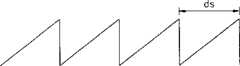
图7A图解了光栅的衍射原理的示例。如果入射角为θi,衍射角为θd,而且光栅栅距为d,则获得下列方程:
其中m是衍射级,λ是入射光的波长。衍射角可以通过改变光栅的形状和特性来控制。此时,如果从光栅衍射的光传播到波导中,光的衍射角必须满足内部全反射角的条件。where m is the diffraction order and λ is the wavelength of the incident light. The diffraction angle can be controlled by changing the shape and properties of the grating. At this time, if the light diffracted from the grating propagates into the waveguide, the diffraction angle of the light must satisfy the condition of the total internal reflection angle.
图7B和7C分别图解了透射型和反射型光栅。图7B中的透射型光栅将入射光改变θ角并在两个方向将其透射。例如,左方向上衍射的光为+1,右方向上衍射的光为-1。标记表示左/右方向,‘1’表示衍射级为‘1’。图7C中的反射型光栅在两个方向上以θ角反射入射光。7B and 7C illustrate transmissive and reflective gratings, respectively. The transmissive grating in Figure 7B changes the incident light by an angle θ and transmits it in two directions. For example, light diffracted in the left direction is +1, and light diffracted in the right direction is -1. Marks indicate left/right direction, '1' indicates that the diffraction order is '1'. The reflective grating in Figure 7C reflects incident light at an angle Θ in both directions.
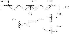
图8A示出了带有波导的可佩戴显示系统,在其上,显示面板802和第一、第二和第三光栅804被放置在用户眼方向的对面。以预定角度从显示面板802发出的光被变向并通过第一光栅804在波导的两个方向上透射,而且以与第一光栅804的衍射角相同的入射角分别入射在第二光栅806和第三光栅808上,此二光栅与第一光栅804有共轭关系。入射在第二光栅806和第三光栅808上的光被以与在第一光栅804上的入射角相同的角度反射并射向用户的眼睛。放大透镜被安装在反射光到达的波导800的左右面,用户可以通过放大透镜观看放大的信号。从此实施例中应注意到,第一光栅804是透射型,第二和第三光栅806和808是反射型。FIG. 8A shows a wearable display system with waveguides on which a
图8B示出了可佩戴显示系统,其中显示面板812被安装在用户眼的对面方向,第一、第二和第三光栅814、816和818被放置在波导的边上——信号通过此边被透射到用户的眼睛。在波导中穿过波导810入射到第一光栅的814的光被以预定角度在两个方向上反射。反射光在波导810中传播,并以与光被第一光栅814衍射的预定角度相同的角度入射到第二和第三光栅816和818上,第二和第三光栅816和818与第一光栅814具有共轭关系。入射光被第二和第三光栅816和818以与第一光栅814的预定入射角度相同的角度透射并向用户的眼睛传播。预定放大透镜被安装在第二和第三光栅816和818上,并放大透射的信号。从此实施例应当注意到,第一光栅814是反射型,第二和第三光栅816和818是透射型。Figure 8B shows a wearable display system where the
图8C示出了可佩戴显示系统的结构,其中显示面板822被安装在用户的眼的方向,第一、第二和第三光栅824、826和828被安装在波导的边上,与信号经其透射到用户眼睛的边相对。从显示面板822通过波导820以预定入射角入射到第一光栅824的光被以预定反射角在第一光栅824在两个方向上反射。反射光在波导820的两个方向上传播并以与第一光栅824的反射角相同的角度入射到第二和第三光栅826和828上——第二和第三光栅826和828与第一光栅824具有共轭关系。入射到第二和第三光栅826和828的光被以与第一光栅824的入射角相同的角度反射,并传播向用户的眼睛。在反射光到达的波导820的两面安装了放大透镜,以便用户可以观看到放大信号。在此实施例中,第一、第二和第三光栅全是反射型。Fig. 8C shows the structure of the wearable display system, in which the display panel 822 is installed in the direction of the user's eyes, the first, second and third gratings 824, 826 and 828 are installed on the sides of the waveguide, and the signal via The side where it transmits to the user's eyes is opposite. Light incident to the first grating 824 at a predetermined incident angle from the display panel 822 through the waveguide 820 is reflected in two directions at the first grating 824 at a predetermined reflection angle. The reflected light propagates in both directions of the waveguide 820 and is incident on the second and third gratings 826 and 828 at the same angle as the reflection angle of the first grating 824—the second and third gratings 826 and 828 being identical to the first The grating 824 has a conjugate relationship. Light incident to the second and third gratings 826 and 828 is reflected at the same angle as the incident angle of the first grating 824, and travels toward the user's eyes. Magnifying lenses are installed on both sides of the waveguide 820 where the reflected light arrives, so that the user can observe the magnified signal. In this embodiment, the first, second and third gratings are all reflective.
图8D示出了可佩戴显示系统的结构,其中在波导830上在用户的眼的方向具有显示面板832和第一、第二和第三光栅834、836和838。从显示面板832以预定入射角入射到第一光栅834的信号光被以预定透射角在波导830中在两个方向上透射。透射光在波导830中传播并随后以与第一光栅834的透射角相同的角度入射到第二和第三光栅836和838上——第二和第三光栅836和838与第一光栅834具有共轭关系。入射光以与第一光栅834的预定入射角相同的角度而透射通过第二和第三光栅836和838的面,并传播向用户的眼睛。附在第二和第三光栅836和828上的放大透镜将待透射的信号放大。在此实施例中,第一、第二和第三光栅834、836和838全是透射型。8D shows the structure of a wearable display system with a display panel 832 and first, second and third gratings 834, 836 and 838 on a waveguide 830 in the direction of the user's eyes. Signal light incident from the display panel 832 to the first grating 834 at a predetermined incident angle is transmitted in two directions in the waveguide 830 at a predetermined transmission angle. The transmitted light propagates in the waveguide 830 and is then incident on the second and third gratings 836 and 838 at the same angle as the transmission angle of the first grating 834 - the second and third gratings 836 and 838 have the same angle as the first grating 834. conjugate relationship. The incident light is transmitted through the faces of the second and third gratings 836 and 838 at the same angle as the predetermined incident angle of the first grating 834, and travels toward the user's eyes. Magnification lenses attached to the second and third gratings 836 and 828 amplify the signal to be transmitted. In this embodiment, the first, second and third gratings 834, 836 and 838 are all transmissive.
图8E图解了可佩戴显示系统的结构,其中在用户的眼的相对方向放置有显示面板842与第二和第三光栅846和848,第一光栅844放置于波导的边上,信号通过它被透射到用户的眼睛。从显示面板842产生并以预定入射角通过波导840入射到第一光栅844的光被以预定反射角从第一光栅844在两个方向上反射。反射光在波导840中的左右方向传播,并随后以与第一光栅844的反射角相同的角度入射到第二和第三光栅846和848上——第二和第三光栅846和848与第一光栅844具有共轭关系。入射光以与第一光栅844的预定入射角相同的角度而从第二和第三光栅846和848反射,并随后传播向用户的眼睛。附在反射光到达的波导840的两个面的放大透镜使得用户可以观看放大的信号。在此实施例中,第一、第二和第三光栅全是反射型。8E illustrates the structure of a wearable display system, wherein a
图8F示出了可佩戴显示系统,其中在用户的眼的对面方向放置有显示面板852与第一光栅854,第二和第三光栅856和858被安装在波导的边上——信号通过此边被透射到用户的眼睛。从显示面板852入射到第一光栅854的光被以预定透射角在波导850的两个方向上透射。透射光在波导850中传播,并随后以与第一光栅854的透射角相同的角度入射到第二和第三光栅856和858上——第二和第三光栅856和858与第一光栅854具有共轭关系。入射光以与第一光栅的预定入射角相同的角度透射通过第二和第三光栅856和858的面,并随后传播向用户的眼睛。预定的放大透镜附在第二和第三光栅856和858上并放大透射信号。在此实施例中,第一、第二和第三光栅854、856和858全是透射型。Figure 8F shows a wearable display system in which a
图8G示出了可佩戴显示系统,其中在用户的眼的方向放置有显示面板862与第二和第三光栅866和868,第一光栅864被安装在波导的与信号透射到用户的眼睛通过的边相对的边上。从显示面板862发出的光通过波导860入射到波导860中的第一光栅864上,并在波导的两个方向上以预定角被反射。反射光在波导860中传播,并以与第一光栅864的反射角相同的角度入射到第二和第三光栅866和868上——第二和第三光栅866和868与第一光栅864具有共轭关系。入射光以与第一光栅的预定入射角相同的角度透射通过第二和第三光栅866和868,并随后传播向用户的眼睛。附在第二和第三光栅866和868上的预定的放大透镜放大透过的信号。在此实施例中,第一光栅864是反射型,第二和第三光栅866和868是透射型。Fig. 8G shows a wearable display system in which a
图8H示出了可佩戴显示系统,其中在用户的眼的方向放置有显示面板872与第一光栅874,第二和第三光栅876和878被安装在波导的与信号透射到用户的眼睛通过的边相对的边上。从显示面板872发出的光以预定入射角度入射到第一光栅874上,并通过第一光栅874在波导870的两个方向上以预定透射角透射。在波导870中透射的光在波导的左右方向上传播,并随后以与第一光栅874的透射角相同的角度入射到第二和第三光栅876和878上——第二和第三光栅876和878与第一光栅874具有共轭关系。入射到第二和第三光栅876和878上的光以与第一光栅874的入射角相同的角度反射并随后传播向用户的眼睛。放大透镜附在反射光到达并使用户可以观看放大的信号的波导的左右边上。在此实施例中,第一光栅874是透射型,第二和第三光栅876和878是反射型。Figure 8H shows a wearable display system in which a display panel 872 and a first grating 874 are placed in the direction of the user's eyes, second and third gratings 876 and 878 are mounted on waveguides and the signal is transmitted to the user's eyes through on the opposite side of the side. Light emitted from the display panel 872 is incident on the first grating 874 at a predetermined incident angle, and is transmitted through the first grating 874 in two directions of the waveguide 870 at a predetermined transmission angle. The light transmitted in the waveguide 870 propagates in the left-right direction of the waveguide and is then incident on the second and third gratings 876 and 878 at the same angle as the transmission angle of the first grating 874—the second and third gratings 876 The sum 878 has a conjugate relationship with the first grating 874 . Light incident on the second and third gratings 876 and 878 is reflected at the same angle as the incident angle of the first grating 874 and then travels toward the user's eyes. Magnifying lenses are attached to the left and right sides of the waveguide where the reflected light reaches and allows the user to view the magnified signal. In this embodiment, the first grating 874 is transmissive and the second and third gratings 876 and 878 are reflective.
如上所述,可以注意到,可以依赖于显示面板和光栅在波导上如何放置而实现各种可佩戴显示系统。在实施例中,如图8A、8B、8E和8F所示,最好显示面板被放置在波导的与信号经其透射到用户眼睛的边相对的边上。As noted above, it can be noted that various wearable display systems can be implemented depending on how the display panel and grating are placed on the waveguide. In an embodiment, as shown in Figures 8A, 8B, 8E and 8F, preferably the display panel is placed on the side of the waveguide opposite the side through which the signal is transmitted to the user's eyes.
图9图解了采用两个显示面板的按照本发明的可佩戴显示系统的另一个实施例。从此系统的结构可以注意到,显示面板920和922被放置在波导的左右方向的较低的部分而不是其中心。第一光栅926和928被分别与显示面板920和922平行安装。与第一光栅926和928有共轭关系的第二光栅930和932被放置在波导924中心附近的用户眼睛的相对方向上。从显示面板920和922发出的信号的光在波导中以预定的透射角通过第一光栅926和928而透射,并且透射的光以与透射角相同的角度入射在第二光栅930和932上。入射在第二光栅930和932上的光在波导924上被以与第一光栅的入射角相同的角度反射并使得反射光传播向用户的眼睛。放大透镜(未示出)被放置在波导的反射光到达的面上并放大图象。在此实施例中,第一光栅926和928是透射型的而第二光栅930和932是反射型的。各种可佩戴显示系统的结构可以通过图9中包括的组件的不同组合而产生,就象各种结构的可佩戴显示系统是通过如图8A-8H所示显示面板的位置和光栅的类型和位置的不同组合而产生的。图8和9示出了一个或两个显示面板与预定数量的对于显示面板足够的光栅的组合,但是显示面板和光栅的数量可以依赖于设计而增加。在此情况下,可佩戴显示系统的多个不同结构可以通过如图8A-8H所示显示面板的位置和光栅的类型和位置的各种组合而产生。Figure 9 illustrates another embodiment of a wearable display system according to the present invention employing two display panels. It can be noticed from the structure of the system that the
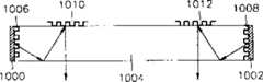
图10A示出了带有安装在波导的两端的显示面板的可佩戴显示系统的实施例。在此结构中,显示面板1000和1002被放置在波导1004的相对的端而不是在边上。第一光栅1006和1008与显示面板1000和1002平行安装。第二光栅1010和1012——与第一光栅有共轭关系——被放置在波导1004的中心附近用户眼睛的相对的方向。从显示面板1006和1008发出的信号的光通过第一光栅1006和1008透射到波导1004中,而且透射光以与透射角相同的角度入射到第二光栅1010和1012。入射到第二光栅1010和1012的光被以与第一光栅的入射角相同的角度反射并使得反射光照向用户的眼睛。在反射光到达的波导的表面,放置放大透镜(未示出)来放大图象。在此实施例中,第一光栅1006和1008是透射型的,第二光栅1010和1012是反射型的。Figure 10A shows an embodiment of a wearable display system with display panels mounted at both ends of a waveguide. In this configuration, the
图10B是在图10A中图解的可佩戴显示系统的另一个实施例,即结构相同但是光栅类型不同。如图10A所示,显示面板1020和1022被放置在波导的两边而不是在边上,第一光栅1026和1028被与显示面板1020和1022平行安装。第二光栅1030和1032——与第一光栅1026和1028有共轭关系——被放置在波导1024中心附近的用户眼睛的方向。从显示面板1020和1022发出的光以预定角度由第一光栅1026和1028透射进波导1024中,透射光以与第一光栅1026和1028相同的透射角入射到第二光栅1030和1032上。入射到第二光栅1030和1032的光以与第一光栅的入射角相同的角度透射并传播向用户的眼睛。透射光通过附在第二光栅1030和1032靠外的边的放大透镜(未示出)而放大。在此实施例中,第一光栅1026和1028以及第二光栅1030和1032全是透射型。Figure 10B is another embodiment of the wearable display system illustrated in Figure 10A, ie the same structure but a different type of grating. As shown in FIG. 10A , the display panels 1020 and 1022 are placed on both sides of the waveguide rather than on the sides, and the first gratings 1026 and 1028 are mounted parallel to the display panels 1020 and 1022 . The second gratings 1030 and 1032 - in conjugate relationship to the first gratings 1026 and 1028 - are placed near the center of the waveguide 1024 in the direction of the user's eyes. Light emitted from the display panels 1020 and 1022 is transmitted into the waveguide 1024 by the first gratings 1026 and 1028 at a predetermined angle, and the transmitted light is incident on the second gratings 1030 and 1032 at the same transmission angle as the first gratings 1026 and 1028 . Light incident to the second gratings 1030 and 1032 is transmitted at the same angle as the incident angle of the first grating and travels toward the user's eyes. The transmitted light is magnified by magnifying lenses (not shown) attached to the outer sides of the second gratings 1030 and 1032 . In this embodiment, the first gratings 1026 and 1028 and the second gratings 1030 and 1032 are all transmissive.
图11图解了采用快门来实现三维图象的按照本发明的可佩戴显示系统。图11的例子是实现了的与图8E相关的三维图象的例子。可以在所有的具有上述结构的可佩戴显示系统中使用快门。用于阻塞在波导的两个方向上传播的光的快门1100和1110在不同时间交替开启和闭合,以便相同的图象在不同时间到达用户的眼睛,因此产生图象看起来象三维图象的效果。虽然在图11中未示出,仅在左或右边中一边带有快门的可佩戴显示系统可以产生相同的三维效果。FIG. 11 illustrates a wearable display system according to the present invention using a shutter to achieve a three-dimensional image. The example of Fig. 11 is an example of a three-dimensional image realized in relation to Fig. 8E. The shutter can be used in all wearable display systems having the above structure. The
如上所述,当同一图象以时间差到达用户的眼睛时实现三维图象。在带有不同折射率的媒体被用作光在其中传播的左右波导的情况下,左和右光栅的栅格间隔不同,或左和右光栅的数量不同,左和右衍射角变得相互不同,因此光传播的距离改变了。作为结果,时间差在进入用户眼睛的最后信号中产生,因此可以获得三维图象效果。当使用在左右两边具有不同媒体的波导时,必须考虑到入射到第一光栅的衍射角依赖于波导的媒体类型的不同而在左和右边不同来栅距第二和第三光栅。而且,必须当左和右光栅的数量不同地设置时在设计光栅过程中考虑衍射角。此时,必须选择波导媒体和必须在假设当全内反射发生时形成衍射角的情况下设计光栅。另一种获得三维图象的方法是使得相同的信号以预定时间差利用两个显示面板而到达用户眼睛。As described above, a three-dimensional image is realized when the same image reaches the user's eyes with a time difference. In the case where media with different refractive indices are used as left and right waveguides in which light propagates, the grating intervals of the left and right gratings are different, or the number of left and right gratings is different, and the left and right diffraction angles become different from each other , so the distance traveled by the light changes. As a result, a time difference is produced in the final signal entering the user's eyes, so that a three-dimensional image effect can be obtained. When using waveguides with different media on the left and right sides, it must be considered that the angle of diffraction incident on the first grating differs depending on the media type of the waveguide and that the second and third gratings are spaced differently on the left and right. Also, it is necessary to consider the diffraction angle in designing the gratings when the numbers of left and right gratings are set differently. At this time, a waveguide medium must be selected and a grating must be designed on the assumption that a diffraction angle is formed when total internal reflection occurs. Another method of obtaining a three-dimensional image is to make the same signal reach the user's eyes with a predetermined time difference using two display panels.
图12A示出了按照本发明的可佩戴显示系统的一个示例,它可以控制瞳孔间的距离(IPD)。大多数成年男人和女人的IPD的范围从50毫米到74毫米。如果用户佩戴的可佩戴显示系统的被设计成针对不同IPD而不同,则左和右图象看起来会不同而且相互重叠,结果是与佩戴适合用户的IPD的可佩戴显示系统的时候相比产生眼睛疲劳。因此。为了调节IPD以使得图象显示更清楚,可佩戴显示系统的放大透镜1200和1210可以移动到与眼瞳孔相对应的位置。Figure 12A shows an example of a wearable display system that can control the interpupillary distance (IPD) in accordance with the present invention. The IPD ranges from 50 mm to 74 mm for most adult men and women. If the wearable display system worn by the user is designed differently for different IPDs, the left and right images will look different and overlap each other, and the result will be different than when wearing the wearable display system for the user's IPD Eye fatigue. therefore. In order to adjust the IPD so that the images are displayed more clearly, the magnifying
图12B图解了可佩戴显示系统的示例,其中包括带有锯齿部件和锯齿放大透镜1200和1210——它们可以与波导1230相结合或相分离——的波导1230,使得用户可以沿着波导1230将放大透镜1200和1210移动预定的距离。这里,放大透镜1200和1210的宽度必须比用于衍射信号的光栅的宽度要窄,而且,放大透镜1200和1210必须仅可在与光栅宽度相同的距离内移动。12B illustrates an example of a wearable display system that includes a
图13是带有单筒结构的可佩戴显示系统的实施例。单筒可佩戴显示系统使用了与图5的双眼显示系统相同的结构和原理,除了它使得用户可以仅以一只眼睛观看图象。单筒显示系统包括显示面板1300、波导1310、第一光栅1320、第二光栅1330和目镜1340。显示面板1300输出通过线路或无线电波从预定信号源(未示出)收到的信号。波导1310使得从显示面板1300发出的信号在一个方向上传播。第一和第二光栅1320和1330衍射穿过波导1310的信号并最终使得信号照向用户的眼睛。这里,第一光栅1320和第二光栅1330具有如上所述的共轭关系,这意味着当以预定入射角入射到第一光栅1320的光被以预定角衍射时,传播通过波导1310的光以与第一光栅1320的衍射角相同的角度入射到第二光栅1322,并且以与第一光栅1320的预定入射角相同的角度被衍射。放大透镜1340将从波导1310发出的信号放大以便对用户来说图象出现得更大。Figure 13 is an embodiment of a wearable display system with a monotube structure. The monocular wearable display system uses the same structure and principle as the binocular display system of Fig. 5, except that it allows the user to view images with only one eye. The monocular display system includes a display panel 1300 , a waveguide 1310 , a first grating 1320 , a second grating 1330 and an eyepiece 1340 . The display panel 1300 outputs a signal received from a predetermined signal source (not shown) through a line or radio wave. The waveguide 1310 allows a signal emitted from the display panel 1300 to propagate in one direction. The first and second gratings 1320 and 1330 diffract the signal passing through the waveguide 1310 and ultimately direct the signal toward the user's eyes. Here, the first grating 1320 and the second grating 1330 have a conjugate relationship as described above, which means that when the light incident on the first grating 1320 at a predetermined incident angle is diffracted at a predetermined angle, the light propagating through the waveguide 1310 is The same angle as the diffraction angle of the first grating 1320 is incident to the second grating 1322 and is diffracted at the same angle as a predetermined incident angle of the first grating 1320 . Magnifying lens 1340 magnifies the signal emanating from waveguide 1310 so that the image appears larger to the user.
图14A-H图解了各种可能的依赖于光栅类型和在波导上的布置的单筒可佩戴显示系统的实施例。14A-H illustrate various possible embodiments of a single-tube wearable display system depending on the grating type and placement on the waveguide.
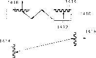
图14A示出了单筒可佩戴显示系统的结构,其中显示面板1402与一和第二光栅1404和1406被放置在波导1400上用户眼睛的相对方向上。从显示面板发出的光以预定角度入射到第一光栅1402上,并随后在波导中的左方向通过第一光栅1404透射,然后以与第一光栅1404的入射角相同的角度入射到第二光栅1406上,第二光栅与第一光栅1404成共轭关系。入射到第二光栅1406的光被以与第一光栅1404的入射角相同的角度反射,并照向用户的眼睛。在光到达的波导1400的表面,安装了一个放大透镜,使得用户可以看到放大的信号。在此实施例中,第一光栅1404是投射型。第二光栅1406是反射型。14A shows the structure of a single-tube wearable display system, where the
图14B示出了单筒可佩戴显示系统,其中显示面板1412被放置在用户眼睛的对面方向,第一和第二光栅1414和1416被安装在经其波导1410的信号透射到用户眼睛所通过的边。以预定入射角入射到波导1410中第一光栅1414的光被以预定反射角向波导的左方向反射。反射光在波导中传播并以与第一光栅1414的反射角相同的角度入射到第二光栅1416上,第二光栅1416与第一光栅1414具有共轭关系。入射光以与第一光栅的预定入射角相同的角度透射出第二光栅1416并照向用户的眼睛。预定的放大透镜被附在第二光栅1416上并放大要透射的信号。在此实施例中,第一光栅1414是反射型的,第二光栅1416为透射型的。14B shows a single-tube wearable display system, wherein the
图14C示出了单筒可佩戴显示系统,其中显示面板1422被放置在用户眼睛的方向,第一和第二光栅1424和1426被安装在波导1420上信号透射到用户眼睛所通过的边的相对的边上。从显示面板1422发出并以预定入射角通过波导1420入射到第一光栅1424的光被以预定反射角在波导1420的左方向反射。反射光在波导1420的左方向传播,并随后以与第一光栅1424的反射角相同的角度入射到第二光栅1426上,第二光栅1426与第一光栅1424具有共轭关系。入射在第二光栅1426的光被反射,并以与第一光栅的入射角相同的角度传播到用户的眼睛。放大透镜被附在波导1420的表面上,并使得用户可以观看放大的信号。在此实施例中,第一和第二光栅1424和1426全是反射型的。14C shows a single-tube wearable display system, wherein the
图14D示出了单筒可佩戴显示系统的结构,其中显示面板1432、第一和第二光栅1434和1436被安装在波导1430上信号透射到用户眼睛所通过的边。从显示面板1432发出并以预定入射角入射到第一光栅1434的信号的光被以预定透射角透射到波导1430中的左方向。透射光在波导1430中传播,并以与第一光栅1434的透射角相同的角度入射到第二光栅1436上,第二光栅1436与第一光栅1434具有共轭关系。入射光被以与第一光栅1434的预定入射角相同的角度透射通过第二光栅1436并传播到用户的眼睛。放大透镜被附在第二光栅1436上并放大要透射的信号。在此实施例中,第一和第二光栅1434和1436全是透射型的。14D shows the structure of a single-tube wearable display system, where the
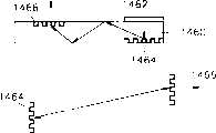
图14E示出了单筒可佩戴显示系统的结构,其中显示面板1442和第二光栅1446被放置在用户眼睛的相对方向上,第一光栅1444被安装在波导1440上信号透射到用户眼睛所通过的边。从显示面板1442发出并以预定入射角通过波导1440入射到第一光栅1444的光被由第一光栅1444以预定反射角向左方向反射。反射光在波导1440的左方向传播,并以与第一光栅1444的反射角相同的角度入射到第二光栅1446上,第二光栅1446与第一光栅1444具有共轭关系。入射光被以与第一光栅的预定入射角相同的角度由第二光栅1446反射并传播到用户的眼睛。放大透镜被附在波导1440的表面上并使得用户可以观看放大的信号。在此实施例中,第一和第二光栅1444和1446全是反射型的。14E shows the structure of a single-tube wearable display system, in which the display panel 1442 and the second grating 1446 are placed in the opposite direction of the user's eyes, and the first grating 1444 is installed on the waveguide 1440 through which the signal is transmitted to the user's eyes. side. Light emitted from the display panel 1442 and incident to the first grating 1444 through the waveguide 1440 at a predetermined incident angle is reflected in a leftward direction by the first grating 1444 at a predetermined reflection angle. The reflected light propagates in the left direction of the waveguide 1440 and is incident on the second grating 1446 at the same angle as the reflection angle of the first grating 1444 , and the second grating 1446 has a conjugate relationship with the first grating 1444 . The incident light is reflected by the second grating 1446 at the same angle as the predetermined incident angle of the first grating and travels to the user's eyes. A magnifying lens is attached to the surface of the waveguide 1440 and allows the user to view the magnified signal. In this embodiment, the first and second gratings 1444 and 1446 are all reflective.
图14F示出了单筒可佩戴显示系统的结构,其中显示面板1452和第一光栅1454被放置在用户眼睛相对的方向上,第二光栅1456安装在波导1450上信号透射到用户眼睛所通过的边。从显示面板1452以预定入射角入射到第一光栅1454的信号的光被以预定透射角透射到波导1450中的左方向。透射光在波导1450中传播,并以与第一光栅1454的透射角相同的角度入射到第二光栅1456上,第二光栅1456与第一光栅1454具有共轭关系。入射光被以与第一光栅的预定入射角相同的角度透射通过第二光栅1456,并传播到用户的眼睛。放大透镜被附在第二光栅1456上并放大要透射的信号。在此实施例中,第一和第二光栅1454和1456全是透射型的。14F shows the structure of a single-tube wearable display system, in which the
图14G示出了单筒可佩戴显示系统的结构,其中显示面板1462和第二光栅1466被放置在波导1460上信号透射到用户眼睛和第一光栅1464所通过的边的相对的边。以预定入射角通过波导1460入射到第一光栅1464的光被以预定反射角向左方向反射。反射光在波导1460中传播并随后以与第一光栅1464的反射角相同的角度入射到第二光栅1466上,第二光栅1466与第一光栅1464具有共轭关系。入射光被以与第一光栅的预定入射角相同的角度透射通过第二光栅1466并传播到用户的眼睛。放大透镜被附在第二光栅1466上并放大要透射的信号。在此实施例中,第一光栅1464是反射型的,第二光栅1466是透射型的。14G shows the structure of a single-tube wearable display system, where the
图14H示出了单筒可佩戴显示系统的结构,其中显示面板1472和第一光栅1474被放置在用户眼睛的方向上,第二光栅1476被安装在波导1470的信号透射到用户眼睛所通过的边。以预定入射角从显示面板1472发出的光被以预定透射角通过第一光栅1474透射到波导1470中的左右方向上。透射到波导1470中的光在波导1460中的左方向传播,并随后以与第一光栅1474的透射角相同的角度入射到第二光栅1476上,第二光栅1476与第一光栅1474具有共轭关系。入射到第二光栅1476的光被以与第一光栅1474的入射角相同的角度反射并传播到用户的眼睛。放大透镜被附在波导1470的表面上并使得用户可以观看放大的信号。在此实施例中,第一光栅1474是透射型的,第二光栅1476是反射型的。14H shows the structure of a single-tube wearable display system, in which the
如上所述,可以注意到多种单筒可佩戴显示系统可依赖于显示面板和波导上光栅的布置而实现。因此,有可能产生具有与以上说明的实施例相同的结构的其他的实施例,但是光的传播方向不同,即光在右方向传播。As mentioned above, it can be noted that various single-tube wearable display systems can be realized depending on the arrangement of gratings on the display panel and waveguide. Therefore, it is possible to produce other embodiments having the same structure as the above-described embodiment, but with a different direction of propagation of light, ie the light travels in the right direction.
图15A是单筒可佩戴显示系统的另一个实施例。在此实施例中显示面板1500被放置在波导1504的端上,第一光栅1506被与显示面板1500平行放置。第二光栅1508位于波导1504的中心的用户眼睛的相对方向上,第二光栅与第一光栅1506具有共轭关系。从显示面板1500发出的信号的光以预定入射角入射到第一光栅1506,并随后以预定透射角通过第一光栅1506透射到波导1504。透射光随后以与透射角相同的角度入射到第二光栅1510上。入射到第二光栅1510的光被以与第一光栅1506的预定入射角相同的相对于第二光栅1510的角度反射并传播到用户的眼睛。放大透镜(未示出)被附在反射光到达的波导1504的表面上并放大信号。在此实施例中,第一光栅1506是透射型的,第二光栅1508是反射型的。Figure 15A is another embodiment of a single-tube wearable display system. In this embodiment the display panel 1500 is placed on the end of the waveguide 1504 and the first grating 1506 is placed parallel to the display panel 1500 . The second grating 1508 is located in the center of the waveguide 1504 in the opposite direction to the user's eye, the second grating having a conjugate relationship with the first grating 1506 . Light of a signal emitted from the display panel 1500 is incident to the first grating 1506 at a predetermined incident angle, and is then transmitted to the waveguide 1504 through the first grating 1506 at a predetermined transmission angle. The transmitted light is then incident on the second grating 1510 at the same angle as the transmission angle. Light incident to the second grating 1510 is reflected at the same angle relative to the second grating 1510 as the predetermined incident angle of the first grating 1506 and travels to the user's eyes. A magnifying lens (not shown) is attached to the surface of the waveguide 1504 where the reflected light reaches and amplifies the signal. In this embodiment, the first grating 1506 is transmissive and the second grating 1508 is reflective.
图15B是与图15A具有相同结构但采用了不同类型的光栅的单筒可佩戴显示系统的又一个实施例。同样在此实施例中,显示面板1520被放置在波导1524的端上,第一光栅1526被与显示面板1520平行放置。第二光栅1530被放置在波导1524的中心的用户眼睛的方向上,第二光栅1530与第一光栅1526具有共轭关系。从显示面板1520发出的信号的光以预定入射角入射到第一光栅1526,并随后以预定透射角通过第一光栅1526透射到波导1524,透射光以与透射角相同的角度入射到第二光栅1530上。入射到第二光栅1530的光被以与第一光栅1526的入射角相同的相对于第二光栅1530的角度反射并传播到用户的眼睛。放大透镜(未示出)被附在反射光到达的波导1524的表面上并放大信号。在此实施例中,第一光栅1526和第二光栅1530全是透射型的。Fig. 15B is yet another embodiment of a single-tube wearable display system having the same structure as Fig. 15A but using a different type of grating. Also in this embodiment, the
在图15A和15B中,显示面板位于波导的左端。然而显示面板的位置可以根据设计而不同。在此情况下,第一光栅不必放置在放置显示面板的波导的相同的端。In Figures 15A and 15B, the display panel is located at the left end of the waveguide. However, the position of the display panel may vary according to design. In this case, the first grating does not have to be placed at the same end of the waveguide where the display panel is placed.
三维图象可以通过同时佩戴上述的两个单筒可佩戴显示系统而实现,每只眼带一个,因此相同的信号被以时间差显示在两个单筒可佩戴显示系统上因此可以获得一个三维图象。A three-dimensional image can be realized by wearing the above two monocular wearable display systems at the same time, one for each eye, so the same signal is displayed on the two monocular wearable display systems with a time difference so that a three-dimensional image can be obtained elephant.
图16A和16B图解了本发明中使用的通过光栅消除色差。色差当入射彩色信号的R、G和B分量的焦点未聚合在一点时发生,即,在不同的地方形成不同的彩色图象。在彩色图象通过本发明使用的光栅传播时,不同的信号可以通过将具有共轭关系的光栅相结合而被聚焦在一处。16A and 16B illustrate the elimination of chromatic aberration by grating used in the present invention. Chromatic aberration occurs when the focal points of the R, G, and B components of an incident color signal do not converge at one point, ie, different color images are formed in different places. When a color image is propagated through the grating used in the present invention, different signals can be focused at one place by combining gratings having a conjugate relationship.
参见图16A,第一光栅1600和第二光栅1610都是透射型的,入射彩色信号的R、G和B彩色分量以不同的透射角透射通过第一光栅1600。每个透射的彩色分量以与第一光栅1600的透射角相同的角度入射在第二光栅1610上,以与第一光栅的入射角相同的入射角透射通过第二光栅1610,并随后与其他平行而入射在诸如目镜透镜的放大透镜1620上。每个平行到达放大透镜1620的彩色分量被通过放大透镜1620以相同的焦距聚焦,因此消除了色差。Referring to FIG. 16A, both the
图16B示出了以预定角角度入射在第一光栅1630的入射信号的R、G和B分量,此时第一和第二光栅1630和1640为透射型光栅。以预定角度入射在第一光栅1630的R、G和B分量以不同的透射角传播,并以与透射角相同的角度入射在第二光栅1640上。每个入射彩色分量以与第一光栅1630的预定入射角相同的角度通过第二光栅1640,并随后平行入射在诸如目镜透镜的放大透镜1650上。放大透镜1650使得平行入射的彩色分量以相同的焦距聚焦,因此消除了色差。色差的消除通过上述的具有共轭关系的光栅获得。FIG. 16B shows R, G and B components of an incident signal incident on the
上述可佩戴显示系统可以通过将波导和光栅或波导和目镜透镜或波导和光栅及目镜透镜合并到一体中而实现。The wearable display system described above may be realized by integrating a waveguide and a grating or a waveguide and an eyepiece lens or a waveguide and a grating and an eyepiece lens into one body.
上述的波导由玻璃或塑料或特别地,由丙烯基底(PMMA)构成。The aforementioned waveguides consist of glass or plastic or, in particular, of acrylic substrate (PMMA).
放大透镜可以由全息光学元件(HOE)或衍射光学元件(DOE)制造。衍射透镜、折射透镜、衍射透镜和折射透镜的结合或非球面镜可以用作放大透镜。The magnifying lens can be fabricated from a holographic optical element (HOE) or a diffractive optical element (DOE). A diffractive lens, a refractive lens, a combination of a diffractive lens and a refractive lens, or an aspheric mirror can be used as the magnifying lens.
图17A至17C图解了可以在本发明中使用的光栅的类型。图17A示出了用于在两个方向上衍射光的矩形二相光栅。图17B示出了锯齿形的仅在一个方向上衍射光的铜焊型光栅。图17C示出了多层的被设计来增进衍射效率的光栅。除了这些类型之外,还可以采用全息光栅。这些光栅可以由HOE和DOE制造。Figures 17A to 17C illustrate the types of gratings that can be used in the present invention. Figure 17A shows a rectangular biphasic grating for diffracting light in two directions. Figure 17B shows a zigzag brazed grating that diffracts light in only one direction. Figure 17C shows a multilayer grating designed to enhance diffraction efficiency. In addition to these types, holographic gratings can also be employed. These gratings can be manufactured by HOE and DOE.
图18A至18E图解了多种目镜透镜。18A to 18E illustrate various eyepiece lenses.
按照上述的本发明,可以通过使光学元器件的数量最小化而实现更轻重量和紧凑的可佩戴显示系统,并且可以减少制造显示系统过程中的复杂性和成本。此外,可以通过将波导、光栅和目镜透镜并为一体而大规模地生产显示系统,而且,可以通过共轭光栅消除色差。According to the present invention as described above, a lighter weight and compact wearable display system can be realized by minimizing the number of optical components, and the complexity and cost in manufacturing the display system can be reduced. In addition, display systems can be mass-produced by integrating waveguides, gratings, and eyepiece lenses, and moreover, chromatic aberration can be eliminated by conjugate gratings.
Claims (57)
Applications Claiming Priority (6)
| Application Number | Priority Date | Filing Date | Title |
|---|---|---|---|
| US25544800P | 2000-12-15 | 2000-12-15 | |
| US60/255,448 | 2000-12-15 | ||
| US25728300P | 2000-12-26 | 2000-12-26 | |
| US60/257,283 | 2000-12-26 | ||
| KR10-2001-0001350AKR100444981B1 (en) | 2000-12-15 | 2001-01-10 | Wearable display system |
| KR1350/01 | 2001-01-10 |
Publications (2)
| Publication Number | Publication Date |
|---|---|
| CN1365016Atrue CN1365016A (en) | 2002-08-21 |
| CN1324347C CN1324347C (en) | 2007-07-04 |
Family
ID=36910854
Family Applications (1)
| Application Number | Title | Priority Date | Filing Date |
|---|---|---|---|
| CNB011436336AExpired - Fee RelatedCN1324347C (en) | 2000-12-15 | 2001-12-14 | Wearable display system |
Country Status (5)
| Country | Link |
|---|---|
| EP (1) | EP1215522B1 (en) |
| JP (1) | JP4064102B2 (en) |
| CN (1) | CN1324347C (en) |
| DE (2) | DE60122658T2 (en) |
| TW (1) | TW522256B (en) |
Cited By (9)
| Publication number | Priority date | Publication date | Assignee | Title |
|---|---|---|---|---|
| CN100533208C (en)* | 2004-12-13 | 2009-08-26 | 诺基亚公司 | Method and system for beam expansion in a display device |
| USRE42992E1 (en) | 2003-02-19 | 2011-12-06 | Mirage Innovations Ltd. | Chromatic planar optic display system |
| CN101529899B (en)* | 2006-09-11 | 2012-07-25 | 斯卡拉株式会社 | Head-mount type display unit, and image display unit |
| CN107193126A (en)* | 2013-11-27 | 2017-09-22 | 奇跃公司 | Virtual and augmented reality System and method for |
| CN107250880A (en)* | 2015-02-09 | 2017-10-13 | 微软技术许可有限责任公司 | Display system based on waveguide |
| CN111240015A (en)* | 2020-01-17 | 2020-06-05 | 北京理工大学 | Diffraction waveguide with uniform double-side outgoing light |
| WO2021027841A1 (en)* | 2019-08-14 | 2021-02-18 | 苏州苏大维格科技集团股份有限公司 | Apparatus for displaying image, and system for implementing augmented reality display |
| CN112882233A (en)* | 2015-05-19 | 2021-06-01 | 奇跃公司 | Double composite light field device |
| CN114051593A (en)* | 2019-07-12 | 2022-02-15 | 三星电子株式会社 | Near-eye display device, augmented reality glasses comprising same, and operation method thereof |
Families Citing this family (60)
| Publication number | Priority date | Publication date | Assignee | Title |
|---|---|---|---|---|
| KR20030088218A (en)* | 2002-05-13 | 2003-11-19 | 삼성전자주식회사 | Wearable color-display system |
| FI114946B (en) | 2002-12-16 | 2005-01-31 | Nokia Corp | Diffractive grating element for balancing diffraction efficiency |
| US7418170B2 (en) | 2004-03-29 | 2008-08-26 | Sony Corporation | Optical device and virtual image display device |
| JP4631308B2 (en)* | 2004-04-30 | 2011-02-16 | ソニー株式会社 | Image display device |
| US7499216B2 (en) | 2004-07-23 | 2009-03-03 | Mirage Innovations Ltd. | Wide field-of-view binocular device |
| US7573640B2 (en) | 2005-04-04 | 2009-08-11 | Mirage Innovations Ltd. | Multi-plane optical apparatus |
| EP1722254B1 (en) | 2005-05-09 | 2010-07-14 | LG Electronics Inc. | Optical system of portable projector and mobile communication terminal using the same |
| EP1760513B1 (en)* | 2005-08-31 | 2010-07-28 | LG Electronics Inc. | Portable projector |
| WO2007141588A1 (en)* | 2006-06-02 | 2007-12-13 | Nokia Corporation | Split exit pupil expander |
| EP2033040B1 (en)* | 2006-06-02 | 2020-04-29 | Magic Leap, Inc. | Stereoscopic exit pupil expander display |
| WO2008071830A1 (en)* | 2006-12-14 | 2008-06-19 | Nokia Corporation | Display device having two operating modes |
| DE102007021036A1 (en)* | 2007-05-04 | 2008-11-06 | Carl Zeiss Ag | Display device and display method for binocular display of a multicolor image |
| US8675279B2 (en)* | 2009-12-15 | 2014-03-18 | Toyota Motor Engineering And Manufacturing North America, Inc. | Grating structure for dividing light |
| WO2013056742A1 (en)* | 2011-10-21 | 2013-04-25 | Patrimoine De L'universite De Liege | Photo-stimulation device |
| JP6246231B2 (en)* | 2013-11-25 | 2017-12-13 | シャープ株式会社 | Light guide and head mounted display |
| JP2015018822A (en)* | 2014-09-24 | 2015-01-29 | パナソニックIpマネジメント株式会社 | Light emitting element |
| EP3062142B1 (en) | 2015-02-26 | 2018-10-03 | Nokia Technologies OY | Apparatus for a near-eye display |
| CA2981652C (en)* | 2015-04-02 | 2023-08-22 | University Of Rochester | Freeform nanostructured surface for virtual and augmented reality near eye display |
| JP6623614B2 (en)* | 2015-08-20 | 2019-12-25 | セイコーエプソン株式会社 | Light guide device and virtual image display device |
| JP6597197B2 (en) | 2015-11-05 | 2019-10-30 | セイコーエプソン株式会社 | Beam diameter expanding element and display device |
| US11231544B2 (en) | 2015-11-06 | 2022-01-25 | Magic Leap, Inc. | Metasurfaces for redirecting light and methods for fabricating |
| AU2017228307B2 (en)* | 2016-02-29 | 2021-11-04 | Magic Leap, Inc. | Virtual and augmented reality systems and methods |
| JP7118007B2 (en) | 2016-04-21 | 2022-08-15 | マジック リープ, インコーポレイテッド | Visual backlight around the field of view |
| GB201609026D0 (en)* | 2016-05-23 | 2016-07-06 | Bae Systems Plc | Waveguide manufacturing method |
| US10466479B2 (en) | 2016-10-07 | 2019-11-05 | Coretronic Corporation | Head-mounted display apparatus and optical system |
| US10650552B2 (en) | 2016-12-29 | 2020-05-12 | Magic Leap, Inc. | Systems and methods for augmented reality |
| EP4300160A3 (en) | 2016-12-30 | 2024-05-29 | Magic Leap, Inc. | Polychromatic light out-coupling apparatus, near-eye displays comprising the same, and method of out-coupling polychromatic light |
| US10409066B2 (en) | 2017-01-19 | 2019-09-10 | Coretronic Corporation | Head-mounted display device with waveguide elements |
| CN108873326A (en) | 2017-05-16 | 2018-11-23 | 中强光电股份有限公司 | Head-mounted display device |
| US10578870B2 (en) | 2017-07-26 | 2020-03-03 | Magic Leap, Inc. | Exit pupil expander |
| KR102858869B1 (en) | 2017-12-10 | 2025-09-11 | 매직 립, 인코포레이티드 | Anti-reflective coatings on optical waveguides |
| CN111712751B (en) | 2017-12-20 | 2022-11-01 | 奇跃公司 | Insert for augmented reality viewing apparatus |
| JP7091674B2 (en)* | 2018-01-26 | 2022-06-28 | セイコーエプソン株式会社 | Display device and light guide device |
| US10755676B2 (en) | 2018-03-15 | 2020-08-25 | Magic Leap, Inc. | Image correction due to deformation of components of a viewing device |
| CN112041727B (en)* | 2018-04-20 | 2022-11-04 | 3M创新有限公司 | Headset and head mounted display |
| US11204491B2 (en) | 2018-05-30 | 2021-12-21 | Magic Leap, Inc. | Compact variable focus configurations |
| JP7319303B2 (en) | 2018-05-31 | 2023-08-01 | マジック リープ, インコーポレイテッド | Radar head pose localization |
| US10825424B2 (en) | 2018-06-05 | 2020-11-03 | Magic Leap, Inc. | Homography transformation matrices based temperature calibration of a viewing system |
| US11092812B2 (en) | 2018-06-08 | 2021-08-17 | Magic Leap, Inc. | Augmented reality viewer with automated surface selection placement and content orientation placement |
| US11579441B2 (en) | 2018-07-02 | 2023-02-14 | Magic Leap, Inc. | Pixel intensity modulation using modifying gain values |
| US11856479B2 (en) | 2018-07-03 | 2023-12-26 | Magic Leap, Inc. | Systems and methods for virtual and augmented reality along a route with markers |
| WO2020010226A1 (en) | 2018-07-03 | 2020-01-09 | Magic Leap, Inc. | Systems and methods for virtual and augmented reality |
| CN112585581B (en) | 2018-07-10 | 2024-10-18 | 奇跃公司 | Thread weaving for cross-ISA procedure calls |
| CN119197613A (en) | 2018-07-24 | 2024-12-27 | 奇跃公司 | Temperature-dependent calibration of mobile detection equipment |
| WO2020023543A1 (en) | 2018-07-24 | 2020-01-30 | Magic Leap, Inc. | Viewing device with dust seal integration |
| WO2020028834A1 (en) | 2018-08-02 | 2020-02-06 | Magic Leap, Inc. | A viewing system with interpupillary distance compensation based on head motion |
| CN116820239A (en) | 2018-08-03 | 2023-09-29 | 奇跃公司 | Fusion gesture based drift correction of fusion gestures for totem in a user interaction system |
| WO2020041615A1 (en) | 2018-08-22 | 2020-02-27 | Magic Leap, Inc. | Patient viewing system |
| WO2020045626A1 (en)* | 2018-08-31 | 2020-03-05 | 富士フイルム株式会社 | Wearable display device |
| EP3881279A4 (en) | 2018-11-16 | 2022-08-17 | Magic Leap, Inc. | Image size triggered clarification to maintain image sharpness |
| CN118409394A (en) | 2018-12-21 | 2024-07-30 | 奇跃公司 | Cavitation structures for promoting total internal reflection in waveguides |
| WO2020163603A1 (en) | 2019-02-06 | 2020-08-13 | Magic Leap, Inc. | Target intent-based clock speed determination and adjustment to limit total heat generated by multiple processors |
| JP2022523852A (en) | 2019-03-12 | 2022-04-26 | マジック リープ, インコーポレイテッド | Aligning local content between first and second augmented reality viewers |
| WO2020223636A1 (en) | 2019-05-01 | 2020-11-05 | Magic Leap, Inc. | Content provisioning system and method |
| WO2021021670A1 (en) | 2019-07-26 | 2021-02-04 | Magic Leap, Inc. | Systems and methods for augmented reality |
| JP7635230B2 (en) | 2019-11-14 | 2025-02-25 | マジック リープ, インコーポレイテッド | Systems and methods for virtual and augmented reality |
| CN114667538A (en) | 2019-11-15 | 2022-06-24 | 奇跃公司 | Viewing system for use in a surgical environment |
| US11269184B2 (en) | 2019-11-20 | 2022-03-08 | Coretronic Corporation | Head-mounted display device |
| EP4231082A1 (en)* | 2022-02-22 | 2023-08-23 | BAE SYSTEMS plc | Improvements in or relating to waveguide display systems |
| EP4483228A1 (en)* | 2022-02-22 | 2025-01-01 | BAE SYSTEMS plc | Improvements in or relating to waveguide display systems |
Family Cites Families (9)
| Publication number | Priority date | Publication date | Assignee | Title |
|---|---|---|---|---|
| US4711512A (en)* | 1985-07-12 | 1987-12-08 | Environmental Research Institute Of Michigan | Compact head-up display |
| US5224198A (en)* | 1991-09-30 | 1993-06-29 | Motorola, Inc. | Waveguide virtual image display |
| US5455693A (en)* | 1992-09-24 | 1995-10-03 | Hughes Aircraft Company | Display hologram |
| US5682255A (en)* | 1993-02-26 | 1997-10-28 | Yeda Research & Development Co. Ltd. | Holographic optical devices for the transmission of optical signals of a plurality of channels |
| US5812186A (en)* | 1994-07-25 | 1998-09-22 | Polaroid Corporation | Three-dimensional display method(s) and apparatus |
| US5724163A (en)* | 1996-11-12 | 1998-03-03 | Yariv Ben-Yehuda | Optical system for alternative or simultaneous direction of light originating from two scenes to the eye of a viewer |
| JP3472068B2 (en)* | 1997-03-19 | 2003-12-02 | 株式会社国際電気通信基礎技術研究所 | 3D image display device |
| JP2000056259A (en)* | 1998-08-10 | 2000-02-25 | Fuji Xerox Co Ltd | Picture display device |
| JP2000267041A (en)* | 1999-03-16 | 2000-09-29 | Fuji Xerox Co Ltd | Head-mounted type color video projection device, color hologram optical element, and manufacture of color hologram optical element |
- 2001
- 2001-11-23TWTW090129026Apatent/TW522256B/ennot_activeIP Right Cessation
- 2001-12-12DEDE60122658Tpatent/DE60122658T2/ennot_activeExpired - Lifetime
- 2001-12-12DEDE60131208Tpatent/DE60131208T2/ennot_activeExpired - Lifetime
- 2001-12-12EPEP01129638Apatent/EP1215522B1/ennot_activeExpired - Lifetime
- 2001-12-14CNCNB011436336Apatent/CN1324347C/ennot_activeExpired - Fee Related
- 2001-12-14JPJP2001382379Apatent/JP4064102B2/ennot_activeExpired - Fee Related
Cited By (16)
| Publication number | Priority date | Publication date | Assignee | Title |
|---|---|---|---|---|
| USRE42992E1 (en) | 2003-02-19 | 2011-12-06 | Mirage Innovations Ltd. | Chromatic planar optic display system |
| CN100533208C (en)* | 2004-12-13 | 2009-08-26 | 诺基亚公司 | Method and system for beam expansion in a display device |
| CN101529899B (en)* | 2006-09-11 | 2012-07-25 | 斯卡拉株式会社 | Head-mount type display unit, and image display unit |
| CN107193126A (en)* | 2013-11-27 | 2017-09-22 | 奇跃公司 | Virtual and augmented reality System and method for |
| CN107315249A (en)* | 2013-11-27 | 2017-11-03 | 奇跃公司 | Virtual and augmented reality System and method for |
| CN107315249B (en)* | 2013-11-27 | 2021-08-17 | 奇跃公司 | Virtual and Augmented Reality Systems and Methods |
| CN107250880A (en)* | 2015-02-09 | 2017-10-13 | 微软技术许可有限责任公司 | Display system based on waveguide |
| CN107250880B (en)* | 2015-02-09 | 2019-07-02 | 微软技术许可有限责任公司 | Display system based on waveguide |
| CN112882233A (en)* | 2015-05-19 | 2021-06-01 | 奇跃公司 | Double composite light field device |
| CN112882233B (en)* | 2015-05-19 | 2023-08-01 | 奇跃公司 | Double composite light field device |
| CN114051593A (en)* | 2019-07-12 | 2022-02-15 | 三星电子株式会社 | Near-eye display device, augmented reality glasses comprising same, and operation method thereof |
| CN114051593B (en)* | 2019-07-12 | 2024-05-03 | 三星电子株式会社 | Near-eye display device, augmented reality glasses including the same, and method of operating the same |
| US12332443B2 (en) | 2019-07-12 | 2025-06-17 | Samsung Electronics Co., Ltd. | Near-eye display device, augmented reality glasses including same, and operating method therefor |
| WO2021027841A1 (en)* | 2019-08-14 | 2021-02-18 | 苏州苏大维格科技集团股份有限公司 | Apparatus for displaying image, and system for implementing augmented reality display |
| CN111240015B (en)* | 2020-01-17 | 2020-12-18 | 北京理工大学 | Diffractive waveguide with uniform output light on both sides |
| CN111240015A (en)* | 2020-01-17 | 2020-06-05 | 北京理工大学 | Diffraction waveguide with uniform double-side outgoing light |
Also Published As
| Publication number | Publication date |
|---|---|
| EP1215522B1 (en) | 2006-08-30 |
| DE60131208T2 (en) | 2008-02-14 |
| EP1215522A3 (en) | 2004-02-04 |
| EP1215522A2 (en) | 2002-06-19 |
| JP2002277818A (en) | 2002-09-25 |
| TW522256B (en) | 2003-03-01 |
| CN1324347C (en) | 2007-07-04 |
| DE60122658T2 (en) | 2006-12-21 |
| DE60122658D1 (en) | 2006-10-12 |
| JP4064102B2 (en) | 2008-03-19 |
| DE60131208D1 (en) | 2007-12-13 |
Similar Documents
| Publication | Publication Date | Title |
|---|---|---|
| CN1365016A (en) | Wearable display system | |
| US6882479B2 (en) | Wearable display system | |
| EP1669792B1 (en) | Wearable display system comprising a waveguide | |
| JP7660649B2 (en) | Stacked Waveguides with Different Gratings for Combined Field of View | |
| JP3612060B2 (en) | Wearable display system | |
| US6611385B2 (en) | Wearable display system | |
| US10007117B2 (en) | Imaging light guide with reflective turning array | |
| CN108027510B (en) | Diffractive backlight display and system | |
| EP1412802B1 (en) | Planar diffractive relay | |
| EP3400477B1 (en) | Imaging light guide with reflective turning array | |
| CN1637460A (en) | Wearable display system adjusting magnification of an image | |
| EP2945002A1 (en) | Image display device, image generating device, and transparent spatial light modulating device | |
| CN113219671A (en) | Optical device and display apparatus | |
| US20230023734A1 (en) | Light guiding apparatus and guiding method thereof | |
| KR102582246B1 (en) | Optical system of augment reality glasses | |
| EP4094116B1 (en) | Light guide and virtual-image display device | |
| CN115480335A (en) | Diffractive waveguide, optical module, and electronic device | |
| TWI770415B (en) | Light guide module and augmented reality apparatus having the same | |
| TWM673168U (en) | Near eye display device | |
| KR20030017941A (en) | Wearable display system | |
| CN116203668A (en) | Waveguide display device | |
| KR20020083738A (en) | Wearable display system and process thereof |
Legal Events
| Date | Code | Title | Description |
|---|---|---|---|
| C06 | Publication | ||
| PB01 | Publication | ||
| C10 | Entry into substantive examination | ||
| SE01 | Entry into force of request for substantive examination | ||
| C14 | Grant of patent or utility model | ||
| GR01 | Patent grant | ||
| CF01 | Termination of patent right due to non-payment of annual fee | ||
| CF01 | Termination of patent right due to non-payment of annual fee | Granted publication date:20070704 Termination date:20161214 |