CN1346456A - portable electronic device - Google Patents
portable electronic deviceDownload PDFInfo
- Publication number
- CN1346456A CN1346456ACN00806123ACN00806123ACN1346456ACN 1346456 ACN1346456 ACN 1346456ACN 00806123 ACN00806123 ACN 00806123ACN 00806123 ACN00806123 ACN 00806123ACN 1346456 ACN1346456 ACN 1346456A
- Authority
- CN
- China
- Prior art keywords
- wing
- electronic device
- portable electronic
- document
- fixing
- Prior art date
- Legal status (The legal status is an assumption and is not a legal conclusion. Google has not performed a legal analysis and makes no representation as to the accuracy of the status listed.)
- Pending
Links
Images


Classifications
- G—PHYSICS
- G06—COMPUTING OR CALCULATING; COUNTING
- G06F—ELECTRIC DIGITAL DATA PROCESSING
- G06F1/00—Details not covered by groups G06F3/00 - G06F13/00 and G06F21/00
- G06F1/16—Constructional details or arrangements
- G06F1/1613—Constructional details or arrangements for portable computers
- G06F1/1633—Constructional details or arrangements of portable computers not specific to the type of enclosures covered by groups G06F1/1615 - G06F1/1626
- G06F1/1684—Constructional details or arrangements related to integrated I/O peripherals not covered by groups G06F1/1635 - G06F1/1675
- G06F1/169—Constructional details or arrangements related to integrated I/O peripherals not covered by groups G06F1/1635 - G06F1/1675 the I/O peripheral being an integrated pointing device, e.g. trackball in the palm rest area, mini-joystick integrated between keyboard keys, touch pads or touch stripes
- G—PHYSICS
- G06—COMPUTING OR CALCULATING; COUNTING
- G06F—ELECTRIC DIGITAL DATA PROCESSING
- G06F1/00—Details not covered by groups G06F3/00 - G06F13/00 and G06F21/00
- G06F1/16—Constructional details or arrangements
- G—PHYSICS
- G06—COMPUTING OR CALCULATING; COUNTING
- G06F—ELECTRIC DIGITAL DATA PROCESSING
- G06F1/00—Details not covered by groups G06F3/00 - G06F13/00 and G06F21/00
- G06F1/16—Constructional details or arrangements
- G06F1/1601—Constructional details related to the housing of computer displays, e.g. of CRT monitors, of flat displays
- G06F1/1603—Arrangements to protect the display from incident light, e.g. hoods
- G—PHYSICS
- G06—COMPUTING OR CALCULATING; COUNTING
- G06F—ELECTRIC DIGITAL DATA PROCESSING
- G06F1/00—Details not covered by groups G06F3/00 - G06F13/00 and G06F21/00
- G06F1/16—Constructional details or arrangements
- G06F1/1613—Constructional details or arrangements for portable computers
- G06F1/1615—Constructional details or arrangements for portable computers with several enclosures having relative motions, each enclosure supporting at least one I/O or computing function
- G06F1/1616—Constructional details or arrangements for portable computers with several enclosures having relative motions, each enclosure supporting at least one I/O or computing function with folding flat displays, e.g. laptop computers or notebooks having a clamshell configuration, with body parts pivoting to an open position around an axis parallel to the plane they define in closed position
- G—PHYSICS
- G06—COMPUTING OR CALCULATING; COUNTING
- G06F—ELECTRIC DIGITAL DATA PROCESSING
- G06F1/00—Details not covered by groups G06F3/00 - G06F13/00 and G06F21/00
- G06F1/16—Constructional details or arrangements
- G06F1/1613—Constructional details or arrangements for portable computers
- G06F1/1633—Constructional details or arrangements of portable computers not specific to the type of enclosures covered by groups G06F1/1615 - G06F1/1626
- G06F1/1637—Details related to the display arrangement, including those related to the mounting of the display in the housing
- G06F1/1647—Details related to the display arrangement, including those related to the mounting of the display in the housing including at least an additional display
- G—PHYSICS
- G06—COMPUTING OR CALCULATING; COUNTING
- G06F—ELECTRIC DIGITAL DATA PROCESSING
- G06F1/00—Details not covered by groups G06F3/00 - G06F13/00 and G06F21/00
- G06F1/16—Constructional details or arrangements
- G06F1/1613—Constructional details or arrangements for portable computers
- G06F1/1633—Constructional details or arrangements of portable computers not specific to the type of enclosures covered by groups G06F1/1615 - G06F1/1626
- G06F1/1684—Constructional details or arrangements related to integrated I/O peripherals not covered by groups G06F1/1635 - G06F1/1675
- G06F1/1686—Constructional details or arrangements related to integrated I/O peripherals not covered by groups G06F1/1635 - G06F1/1675 the I/O peripheral being an integrated camera
- H—ELECTRICITY
- H04—ELECTRIC COMMUNICATION TECHNIQUE
- H04N—PICTORIAL COMMUNICATION, e.g. TELEVISION
- H04N1/00—Scanning, transmission or reproduction of documents or the like, e.g. facsimile transmission; Details thereof
- H04N1/00127—Connection or combination of a still picture apparatus with another apparatus, e.g. for storage, processing or transmission of still picture signals or of information associated with a still picture
- H04N1/00204—Connection or combination of a still picture apparatus with another apparatus, e.g. for storage, processing or transmission of still picture signals or of information associated with a still picture with a digital computer or a digital computer system, e.g. an internet server
- H04N1/00236—Connection or combination of a still picture apparatus with another apparatus, e.g. for storage, processing or transmission of still picture signals or of information associated with a still picture with a digital computer or a digital computer system, e.g. an internet server using an image reading or reproducing device, e.g. a facsimile reader or printer, as a local input to or local output from a computer
- H04N1/00241—Connection or combination of a still picture apparatus with another apparatus, e.g. for storage, processing or transmission of still picture signals or of information associated with a still picture with a digital computer or a digital computer system, e.g. an internet server using an image reading or reproducing device, e.g. a facsimile reader or printer, as a local input to or local output from a computer using an image reading device as a local input to a computer
- H—ELECTRICITY
- H04—ELECTRIC COMMUNICATION TECHNIQUE
- H04N—PICTORIAL COMMUNICATION, e.g. TELEVISION
- H04N1/00—Scanning, transmission or reproduction of documents or the like, e.g. facsimile transmission; Details thereof
- H04N1/04—Scanning arrangements, i.e. arrangements for the displacement of active reading or reproducing elements relative to the original or reproducing medium, or vice versa
- H04N1/19—Scanning arrangements, i.e. arrangements for the displacement of active reading or reproducing elements relative to the original or reproducing medium, or vice versa using multi-element arrays
- H04N1/195—Scanning arrangements, i.e. arrangements for the displacement of active reading or reproducing elements relative to the original or reproducing medium, or vice versa using multi-element arrays the array comprising a two-dimensional array or a combination of two-dimensional arrays
- H04N1/19594—Scanning arrangements, i.e. arrangements for the displacement of active reading or reproducing elements relative to the original or reproducing medium, or vice versa using multi-element arrays the array comprising a two-dimensional array or a combination of two-dimensional arrays using a television camera or a still video camera
- H—ELECTRICITY
- H04—ELECTRIC COMMUNICATION TECHNIQUE
- H04N—PICTORIAL COMMUNICATION, e.g. TELEVISION
- H04N1/00—Scanning, transmission or reproduction of documents or the like, e.g. facsimile transmission; Details thereof
- H04N1/04—Scanning arrangements, i.e. arrangements for the displacement of active reading or reproducing elements relative to the original or reproducing medium, or vice versa
- H04N1/19—Scanning arrangements, i.e. arrangements for the displacement of active reading or reproducing elements relative to the original or reproducing medium, or vice versa using multi-element arrays
- H04N1/195—Scanning arrangements, i.e. arrangements for the displacement of active reading or reproducing elements relative to the original or reproducing medium, or vice versa using multi-element arrays the array comprising a two-dimensional array or a combination of two-dimensional arrays
- H—ELECTRICITY
- H04—ELECTRIC COMMUNICATION TECHNIQUE
- H04N—PICTORIAL COMMUNICATION, e.g. TELEVISION
- H04N2201/00—Indexing scheme relating to scanning, transmission or reproduction of documents or the like, and to details thereof
- H04N2201/0008—Connection or combination of a still picture apparatus with another apparatus
- H04N2201/0063—Constructional details
- H—ELECTRICITY
- H04—ELECTRIC COMMUNICATION TECHNIQUE
- H04N—PICTORIAL COMMUNICATION, e.g. TELEVISION
- H04N2201/00—Indexing scheme relating to scanning, transmission or reproduction of documents or the like, and to details thereof
- H04N2201/04—Scanning arrangements
- H04N2201/0402—Arrangements not specific to a particular one of the scanning methods covered by groups H04N1/04 - H04N1/207
- H04N2201/0422—Media holders, covers, supports, backgrounds; Arrangements to facilitate placing of the medium
Landscapes
- Engineering & Computer Science (AREA)
- General Engineering & Computer Science (AREA)
- Theoretical Computer Science (AREA)
- Computer Hardware Design (AREA)
- Physics & Mathematics (AREA)
- General Physics & Mathematics (AREA)
- Human Computer Interaction (AREA)
- Multimedia (AREA)
- Signal Processing (AREA)
- Computing Systems (AREA)
- Mathematical Physics (AREA)
- Studio Devices (AREA)
- Casings For Electric Apparatus (AREA)
Abstract
Description
Translated fromChinese发明领域field of invention
本发明涉及便携式电子设备。The present invention relates to portable electronic devices.
背景技术Background technique
在JP-A-10164414中公开了一种已知的包括光传感器的电子设备。数码相机单元设置在笔记本个人计算机的显示屏附近。这种数码相机单元包括:长的、不透明的圆筒,其能够自由地绕它的长轴旋转,并且具有一个从圆筒表面上切去的窄缝形窗口,使得上述圆筒的外观类似于邮筒。圆环形的反射镜设置在圆筒内上述窗口后面,其能够倾斜使得通过窗口的光能够向下反射到圆筒的轴上,并通过轴向安装的透镜聚焦到放置在圆筒底部的电荷耦合器件的表面。A known electronic device including a light sensor is disclosed in JP-A-10164414. A digital camera unit is provided near the display screen of the notebook personal computer. This digital camera unit consists of a long, opaque cylinder that is free to rotate about its long axis and has a slit-shaped window cut from the surface of the cylinder, giving the cylinder an appearance similar to mailbox. A circular reflector is placed behind the aforementioned window in the cylinder and can be tilted so that light passing through the window is reflected down the axis of the cylinder and focused by an axially mounted lens onto a charge placed at the bottom of the cylinder. surface of the coupling device.
相机单元可以旋转使得可以观察到支撑在垂直支架上的文件并捕捉到影像。这种布置具有以下几个缺点:首先,相机和文件安装在相互独立的表面,使得如果笔记本计算机或支架受到撞击或振动,那么捕捉到的影像就会模糊。第二,使用者必须在捕捉影像前将文件和相机精确对准,这是一个浪费时间的过程并且包括通过反复实验来定位文件支架的步骤。第三,必须分别携带支架,这样增加了使用者必须携带的物品的数量。The camera unit can be rotated to view and capture images of documents supported on the vertical stand. This arrangement has several disadvantages: First, the camera and file are mounted on separate surfaces, so that if the laptop or stand is subject to shock or vibration, the captured image will be blurred. Second, the user must precisely align the document with the camera before capturing an image, a time-consuming process that involves trial and error to position the document holder. Third, the stands must be carried separately, which increases the number of items the user must carry.
在US-A-5610730中公开了一种包括图像传感器的笔记本计算机。数码相机用于捕捉平放在桌子上的或者在其它放置计算机的表面上的文件的图像。但是,与JP-A-10164414中描述的布置相同,这种配置由于震动或文件相对于相机的未对准会引起影像质量的下降。A notebook computer comprising an image sensor is disclosed in US-A-5610730. Digital cameras are used to capture images of documents lying flat on a desk or other surface on which a computer is placed. However, like the arrangement described in JP-A-10164414, this configuration causes degradation of image quality due to vibration or misalignment of the document with respect to the camera.
本发明旨在改善上述问题。The present invention aims to improve the above-mentioned problems.
发明内容 Contents of the invention
根据本发明,提供了一种包括电子设备,其包括互相铰接在一起的第一翼和第二翼,光传感器安装在上述第一翼上,其中光传感器被配置成用于感测平放在第二翼上的文件。According to the present invention, there is provided an electronic device comprising a first wing hinged to each other and a second wing, on which a light sensor is mounted, wherein the light sensor is configured to sense Files on the second wing.
因此,光传感器可以这样配置,使得其所对方向垂直于第二翼并且基本聚焦在第二翼上。Accordingly, the light sensor may be configured such that it faces perpendicular to the second wing and is substantially focused on the second wing.
键盘可以设置在第二翼上并且显示屏在第一翼上。The keyboard may be provided on the second wing and the display screen on the first wing.
也可以,将键盘设置在第一翼上,将显示屏设置在第二翼上。It is also possible to arrange the keyboard on the first wing and the display screen on the second wing.
优选地,便携式电子设备可以包括摄影用闪光装置。这类便携式电子设备具有文件能够被均匀照射的优点。Preferably, the portable electronic device may include a flash device for photography. Such portable electronic devices have the advantage that documents can be uniformly illuminated.
光传感器所对方向可以相对于第一翼改变。The direction towards which the light sensor is directed may change relative to the first wing.
文件可以通过固定装置固定到第二翼上。Documents can be secured to the second wing by means of securing devices.
优选地,固定装置包括:夹持装置,用于将文件固定在第二翼和夹持装置之间。Preferably, the securing means comprises: clamping means for securing the document between the second wing and the clamping means.
因此,夹持装置可以包括固定带,并且可以从卷轴上拉出固定带。Thus, the holding means may comprise a fixing strap and the fixing strap may be drawn from the reel.
附图的详细说明Detailed description of the drawings
下面通过示例参照附图描述本发明的实施例,其中:Embodiments of the invention are described below by way of example with reference to the accompanying drawings, in which:
图1是本发明第一实施例的透视图;Figure 1 is a perspective view of a first embodiment of the present invention;
图2a是将较大的文件固定在便携式个人计算机的显示屏上的平面图;Figure 2a is a plan view of fixing larger files on the display screen of a portable personal computer;
图2b是将较小的文件固定在便携式个人计算机的显示屏上的平面图;Figure 2b is a plan view of fixing smaller files on the display screen of a portable personal computer;
图3是在第一实施例中使用的相机单元的放大视图;Fig. 3 is an enlarged view of a camera unit used in the first embodiment;
图4是在第一实施例中使用的闪光单元的放大视图;Fig. 4 is an enlarged view of the flash unit used in the first embodiment;
图5是本发明第二实施例的透视图;Figure 5 is a perspective view of a second embodiment of the present invention;
图6是本发明第三实施例的透视图;Figure 6 is a perspective view of a third embodiment of the present invention;
图7是本发明第四实施例的透视图;Figure 7 is a perspective view of a fourth embodiment of the present invention;
图8是用于储存和输出透明塑料带的机构的放大视图;Figure 8 is an enlarged view of a mechanism for storing and outputting transparent plastic strips;
图9是本发明第五实施例的透视图;Figure 9 is a perspective view of a fifth embodiment of the present invention;
图10是用于在个人计算机的一翼的整个表面上从一端到另一端滑动固定带的机构的放大视图;10 is an enlarged view of the mechanism for sliding the securing strap from one end to the other over the entire surface of a wing of a personal computer;
图11是本发明第六实施例的透视图;11 is a perspective view of a sixth embodiment of the present invention;
图12a是本发明第七实施例的剖视图;Fig. 12a is a cross-sectional view of a seventh embodiment of the present invention;
图12b是本发明第七实施例的平面图;Fig. 12b is a plan view of a seventh embodiment of the present invention;
图13是本发明第八实施例的透视图;13 is a perspective view of an eighth embodiment of the present invention;
图14是在本发明第八实施例中使用的相机单元的剖视图;14 is a sectional view of a camera unit used in an eighth embodiment of the present invention;
图15a是在本发明第八实施例中使用的可选相机单元的剖视图;以及Figure 15a is a cross-sectional view of an optional camera unit for use in an eighth embodiment of the invention; and
图15b是可选相机单元的平面图。Figure 15b is a plan view of an optional camera unit.
优选实施例的详细描述第一实施例Detailed Description of Preferred Embodiments First Embodiment
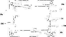
参见图1和图2,在本发明的第一实施例中,便携式个人计算机1包括:第一翼2和第二翼3,它们通过元件4a,4b沿第一长边4铰接在一起。这种布置使得当个人计算机不用时,两翼2,3能够折叠在一起。第一翼2的向内的表面具有键盘5、跟踪板控制器6、相机单元7和闪光单元8a,8b。第一翼2还具有电源插孔9、输入/输出端口10、3.5英寸磁盘驱动器11、硬盘驱动器12和主板13。第二翼3的向内的表面具有显示屏14和用于将诸如名片之类的文件16固定到第二翼3的向内的表面上的固定装置15。1 and 2, in a first embodiment of the present invention, a portable
固定装置15包括:长的、平直的由塑性树脂材料制成的第一、第二、第三和第四固定夹15a、15b、15c和15d。固定夹15固定在第二翼3的向内的表面的各个角上使得它们平压在向内的表面上。固定夹15a、15b、15c和15d的自由端可以从表面上拉起,但是释放后会再一次回到原位平压在表面上。固定夹15a、15b、15c和15d可绕它们的固定点旋转。当不使用时,固定夹旋转到平行于第二翼3的各边,不遮挡显示屏14。The fixing device 15 includes long, straight first, second, third and
通过将文件的边或角利用固定夹15a、15b、15c和15d固定,不同尺寸的文件可以固定到第二翼3的表面。图2a示出了一个较大的文件,例如A5纸的文件16a,在它的四边用固定夹15a、15b、15c和15d固定。图2b示出了同样的固定夹15a、15b、15c和15d将较小的文件,例如名片16b,固定到第二翼3的表面。Documents of different sizes can be secured to the surface of the
铰链4a、4b是摩擦固定型的,并且允许第二翼3相对于第一翼2扫过的角度在0到120度之间。铰链4a、4b在大约50度的位置上安装有一个挡块,以通知用户第二翼3处于拍摄文件16的正确位置。The hinges 4a, 4b are of the friction-fixed type and allow the
参见图3,相机单元7包括一个电荷耦合器件成像传感器17和透镜18。电荷耦合器件17和透镜18设置在长的盒形可折下单元19的相对两端。透镜18将通过它的光聚焦到电荷耦合器件17。Referring to FIG. 3 , the
当相机单元7不使用时,可折下单元19处于第一翼2的凹槽20中。这就是“折下”的位置。可折下单元19在凹槽20内通过摩擦固定铰链21连接到第一翼2。为了使用相机单元7,可折下单元19的最上面的表面22被压下并且延伸/缩回机构(未示出)将单元19升高到“抬起”的位置。在这个位置,可折下单元19可以相对于第一翼2成40度角,并且当透镜18在拍摄位置时,透镜18指向第二翼3的中心。The fold-down
参见图4,第一闪光单元8a具有设置在长的、盒形可折下单元25a中的第一电子闪光灯泡24a。当不使用闪光单元8a时,可折下单元25a在第一翼2中设置的凹槽26a中。这就是“折下”位置。折下的单元25a在凹槽26a中被通过摩擦固定铰链27a连接到第一翼2。为了使用闪光单元8a,可折下单元25a的最上面的表面28a被压下并且延伸/缩回机构(未示出)将单元25a升高到“抬起”的位置。在这个位置上,电子闪光灯泡24b可以照亮第二翼3。Referring to FIG. 4, the first flash unit 8a has a first electronic flash bulb 24a disposed in a long, box-shaped foldable unit 25a. When the flash unit 8a is not in use, the fold-down unit 25a is in a groove 26a provided in the first wing 2 . This is the "fold down" position. The folded down unit 25a is connected to the first wing 2 in the groove 26a by a frictionally fixed hinge 27a. To use flash unit 8a, the uppermost surface 28a of the foldable unit 25a is depressed and an extension/retraction mechanism (not shown) raises the unit 25a to a "raised" position. In this position, the electronic flash bulb 24b can illuminate the
下面描述如何定位文件并捕捉文件的影像。The following describes how to locate the file and capture an image of the file.
假设打开便携式个人计算机并操作,使用者将折下的相机和闪光单元19、25a、25b升高到“抬起”的位置。使用者选择并运行用于控制相机单元7、捕捉影像并将捕捉到的影像存为文件的软件。该软件还可以编辑捕捉到的影像。使用者从拉下的菜单中选择将要捕捉的影像的尺寸。软件提示使用者将文件16用固定夹15固定在第二翼3,将第二翼3定位在拍摄位置,然后按下按键来捕捉影像。当按动按键时,软件使得文件16后面的显示屏14为空白,并当通过相机单元7捕捉影像的时候触发闪光单元8a、8b。影像被存储为文件,并在显示屏14上显示以供使用者观看。使用者重新将显示屏14定位成观看位置,移去文件16并且在显示屏14上观看捕捉到的影像。第二实施例Assuming the portable personal computer is turned on and operating, the user raises the folded down camera and
参见图5,在本发明的第二实施例中,便携式个人计算机31包括:通过元件34a、34b沿长边34铰接在一起的第一翼32和第二翼33。这种布置在个人计算机不使用时使得两翼32、33能够折叠在一起。第一翼32的向内的表面具有薄膜键盘35、跟踪板控制器36、用于将诸如名片之类的文件38固定到第一翼32的向内的表面的固定装置37。第一翼32还具有电源插孔39、输入/输出端口40、3.5英寸磁盘驱动器41、硬盘驱动器42、主板43。第二翼33的向内的表面包括:显示屏44、相机单元45、闪光单元46a、46b和薄膜控制按钮47。Referring to FIG. 5, in a second embodiment of the present invention, a portable
固定装置37包括:与第一实施例中的固定夹一样的固定夹37a、37b、37c、37d。固定夹37设置在第一翼33的向内的表面的四个角,使得它们平压在该表面上。The fixing device 37 includes fixing
除了相机单元被收藏在第二翼33内之外,相机单元45在结构上与如图3所示的结构一样。The
下面描述如何定位文件和捕捉文件的影像。The following describes how to locate files and capture images of files.
假设打开便携式个人计算机并操作,使用者将折下的相机和闪光单元45、46a、46b升高到“抬起”的位置。使用者选择并运行用于控制相机单元45、捕捉影像并将捕捉到的影像存为文件的软件。该软件还可以编辑捕捉到的影像。使用者从拉下的菜单中选择将要捕捉的影像的尺寸。软件提示使用者将文件38用固定夹37固定在第一翼32,将第二翼33定位在拍摄位置,然后按下薄膜控制按钮47来捕捉影像。当按动按钮时,软件使得文件38后面的显示屏36为空白,并当通过相机单元45捕捉影像的时候触发闪光单元46a、46b。影像被存储为文件,并在显示屏44上显示以供使用者观看。使用者重新将第二翼33定位成观看位置,移去文件38并且在显示屏44上观看捕捉到的影像。第三实施例Assuming the portable personal computer is turned on and operating, the user raises the folded down camera and
参见图6,在本发明的第三实施例中,电子图书61包括沿长边64通过元件64a、64b铰接在一起的第一翼62和第二翼63。这种布置使得在电子图书不用时两翼62、63能够折叠在一起。第一翼62的向内的表面具有第一显示屏64、第一薄膜键盘65、用于将诸如名片之类的文件67固定到第一翼62的向内的表面的固定装置66。第一翼62还具有电源插孔68、输入/输出端口69、存储器单元和逻辑电路板。第二翼63的向内的表面包括:第二显示屏70、相机单元71、闪光单元72a、72b和第二薄膜控制板73。Referring to FIG. 6, in a third embodiment of the present invention, an electronic book 61 includes a first wing 62 and a second wing 63 hinged together along a long side 64 by elements 64a, 64b. This arrangement allows the wings 62, 63 to be folded together when the electronic book is not in use. The inward facing surface of the first wing 62 has a first display screen 64 , a first membrane keypad 65 , securing means 66 for securing documents 67 such as business cards to the inward facing surface of the first wing 62 . The first wing 62 also has a power jack 68, input/output ports 69, memory units and a logic circuit board. The inward facing surface of the second wing 63 includes: a second display screen 70 , a camera unit 71 , flash units 72a, 72b and a second membrane control panel 73 .
固定装置66包括:平的矩形的固定夹66a、66b、66c、66d。固定夹66被设置在第一翼62的向内的表面的各个边的中间,使得它们平压在表面上。固定装置66也可以与在第一实施例中使用的固定装置相同。The fixing device 66 includes: flat rectangular fixing clips 66a, 66b, 66c, 66d. Retention clips 66 are positioned intermediate the sides of the inwardly facing surface of first wing 62 so that they lie flat against the surface. The fixing means 66 may also be the same as that used in the first embodiment.
除了单元被收藏在第二翼63内之外,相机单元71在结构上与如图3所示的结构一样。The camera unit 71 is structurally the same as that shown in FIG. 3 except that the unit is stowed within the second wing 63 .
下面描述如何定位文件并捕捉文件的影像。The following describes how to locate the file and capture an image of the file.
假设打开电子图书61并操作,使用者将折下的相机和闪光单元71、72a、72b升高到“抬起”的位置。使用者选择并运行用于控制相机单元71、捕捉影像并将捕捉到的影像存为文件的软件。使用者从拉下的菜单中选择将要捕捉的影像的尺寸。软件提示使用者将文件67用固定夹66固定在第一翼62,将第二翼63的角度调整成拍摄位置,然后按下第二薄膜控制板73来捕捉影像。当按动控制板时,软件使得第一和第二显示屏64、70为空白,并当通过相机单元71捕捉影像的时候触发闪光单元72a、72b。影像被存储为文件,并在第一显示屏64上显示以供使用者观看。使用者重新将第二翼63定位成观看位置,移去文件67并且在第一显示屏64上观看捕捉到的影像。第四实施例Assuming the electronic book 61 is opened and operated, the user raises the folded down camera and flash unit 71, 72a, 72b to the "raised" position. The user selects and runs the software for controlling the camera unit 71, capturing images and saving the captured images as files. The user selects the size of the image to be captured from the pull-down menu. The software prompts the user to fix the document 67 on the first wing 62 with the fixing clip 66, adjust the angle of the second wing 63 to the shooting position, and then press the second membrane control plate 73 to capture the image. When the control pad is pressed, the software blanks the first and second display screens 64, 70 and triggers the flash units 72a, 72b when an image is captured by the camera unit 71 . The images are stored as files and displayed on the first display screen 64 for viewing by the user. The user repositions the second wing 63 to the viewing position, removes the document 67 and views the captured image on the first display screen 64 . Fourth embodiment
参见图7和图8,在本发明的第四实施例中,便携式个人计算机91包括:沿长边94通过元件94a、94b铰接在一起的第一翼92和第二翼93。第二翼93具有固定装置95和显示屏96。7 and 8, in a fourth embodiment of the present invention, a portable
除了固定装置95包括第一、第二、第三和第四可延长的透明带95a、95b、95c、95d外,该个人计算机与图1中的个人计算机一样。上述固定带95a、95b、95c、95d由透明的塑料树脂材料制成。这些固定带绕在第一、第二、第三和第四卷轴97a、97b、97c、97d上,上述四个卷轴设置在显示屏96和第二翼93的边缘之间的悬挂支架98上。The personal computer is the same as the personal computer of FIG. 1 except that the fixing means 95 includes first, second, third and fourth extendable
看到第二翼93的向内的表面,第一和第二卷轴97a、97b被安装在上支架98a,上支架98a沿着第二翼93的上边缘。第三和第四卷轴97c、97d被安装在左支架98b上,左支架98b沿第二翼93的左边缘。Viewing the inwardly facing surface of the
更详细地考虑到第一卷轴97a的布置。固定带95a的一端被固定在卷轴的轴上并绕在上面。卷轴97a在轮轴98a上绕轮轴98a自由旋转。一个平的线圈恒定力弹簧99a被在其外端设置到卷轴97a的轮缘。弹簧99a的内端被固定在轮轴98a。承载着卷轴97a的轮轴98a和弹簧99a被安装在接收槽100a或者悬挂支架98中的空腔101a的任意一侧中。夹持装置102a被固定到固定带的自由端。夹持装置102a包括:矩形金属板,它的一个边向回卷曲。在剖视图中,夹子的形状为字母“J”形。Consider the arrangement of the
固定带的自由端被使用者从一翼的边缘拉出,跨过表面到达另一个平行边,在那里设有一个用于接收夹持装置102a并与之接合的接收装置103a。这样固定带95a跨过第二翼91的表面定位。The free end of the strap is pulled by the user from the edge of one wing, across the surface to the other parallel edge, where a receiving means 103a is provided for receiving and engaging the holding means 102a. The securing
第二、第三和第四卷轴97b、97c、97d通过与第一卷轴97a相同的方式安装到支架98内。同样,第二、第三和第四固定带95b、95c、95d被通过夹持装置102b、102c、102d安装,该夹持装置102b、102c、102d被接收装置103b、103c、103d接收并与之接合。The second, third and fourth reels 97b, 97c, 97d are mounted in the
下面描述文件104的固定。Fixing of the
使用者将文件104平放在第二翼93上,将第一固定带95a通过夹子102a拉出并且从卷轴97a拉出固定带95a。夹子102a夹到接收器103a上。固定带95a的任何松动都通过弹簧99a拉紧,并且使得固定带被拉过第二翼96的表面。这样将文件104固定到第二翼93的表面上,使用者同样地使用第二、第三和第四固定带95b、95c、95d。通过这种方式,这个文件通过固定带95组成的网格被固定在第二翼93上。第五实施例The user lays the
参见图9和图10,在本发明的第五实施例中,便携式个人计算机121包括:沿长边124通过元件124a、124b铰接在一起的第一翼122和第二翼123。第二翼123具有固定装置125和显示屏126。9 and 10, in a fifth embodiment of the present invention, a portable personal computer 121 includes a first wing 122 and a second wing 123 hinged together along a long side 124 by elements 124a, 124b. The second wing 123 has a fixing device 125 and a display screen 126 .
除了固定装置125包括第一、第二、第三和第四固定延长的透明带125a、125b、125c、125d以外,该个人计算机与图7中的个人计算机一样。固定带125a、125b、125c、125d由透明塑料树脂材料制成。第一和第二固定带125a、125b互相平行,并且挂到设置在悬挂支架128内的第一和第三杆127a、127c上,上述悬挂支架128在显示屏126和第二翼123的边缘之间。垂直于第一和第二固定带125a、125b的第三和第四固定带125c、125d被挂到第二和第四杆127b、127d上。The personal computer is the same as the personal computer in FIG. 7 except that the fixing means 125 includes first, second, third and fourth fixed elongated
通过在至少两个平行的固定带125下面滑动文件,将文件130固定在第二翼123上。The document 130 is secured to the second wing 123 by sliding the document under at least two parallel securing straps 125 .
更详细地观看第一固定带125a,第一固定带125a的一端绕在并且粘到护套129a上,该护套能够在第一杆127a上自由向上或向下滑动。第一固定带125a的另一端也以相似方式固定在第三杆127a上。通过这种方式,第一固定带125a可以在第二翼123的整个平面内移动。同样,第二固定带125b也可以在第二翼123的整个表面移动。结果,第一固定带和第二固定带125a、125b之间的间隔是可变的,使得可以放置不同尺寸的文件。第三和第四固定带125a、125b也同样可移动。Looking at the
固定文件和捕捉文件影像的方法与上述第四实施例中描述的相似。第六实施例The method of fixing the document and capturing the image of the document is similar to that described in the fourth embodiment above. Sixth embodiment
参见图11,在本发明的第六实施例中,手持式个人计算机151包括:通过元件155a、155b沿第一长边155铰接在一起的第一翼152和第二翼153。这种布置使得当个人计算机不使用时,两翼152、153能够折叠在一起。第一翼152的向内的表面具有显示器156、第一和第二由拇指操作的操纵杆157a、157b、第一和第二控制按钮158a、158b、相机单元159和第一和第二闪光单元160a、160b。第一翼151还具有电源插孔161、输入/输出端口162、存储模块(未示出)、主板(未示出)、第一和第二话筒163a、163b以及第一和第二扬声器164a、164b。第二翼153的向内的表面包括:固定装置165,用于将诸如名片之类的文件166固定到第二翼153的向内的表面上。Referring to FIG. 11 , in a sixth embodiment of the present invention, a handheld personal computer 151 includes a first wing 152 and a second wing 153 hinged together along a first long side 155 by elements 155a, 155b. This arrangement allows the wings 152, 153 to be folded together when the personal computer is not in use. The inward facing surface of the first wing 152 has a display 156, first and second thumb operated joysticks 157a, 157b, first and second control buttons 158a, 158b, a camera unit 159 and first and second flash units 160a, 160b. The first wing 151 also has a power jack 161, input/output ports 162, a memory module (not shown), a motherboard (not shown), first and second microphones 163a, 163b and first and second speakers 164a, 164b. The inwardly facing surface of the second wing 153 includes securing means 165 for securing documents 166 , such as business cards, to the inwardly facing surface of the second wing 153 .
第一和第二翼152、153的最左边的相邻边通过第一遮盖装置167a桥接在一起,上述第一遮盖装置167a包括可折叠的扇形元件。同样,第一和第二翼152、153的最右边的相邻边通过第二遮盖装置167b桥接在一起,上述第二遮盖装置167b包括可折叠的扇形元件。上述第一和第二遮盖装置167a、167b由耐用的不透明的塑料树脂材料制成。The leftmost adjacent sides of the first and second wings 152, 153 are bridged together by first covering means 167a comprising foldable fan-shaped elements. Likewise, the rightmost adjacent sides of the first and second wings 152, 153 are bridged together by second covering means 167b comprising foldable fan-shaped elements. The above-mentioned first and second cover means 167a, 167b are made of a durable opaque plastic resin material.
固定装置165可以与在第一、第三、第四或第五实施例中使用的固定装置165相似。第七实施例The fixing means 165 may be similar to the fixing means 165 used in the first, third, fourth or fifth embodiments. Seventh embodiment
参见图12a和12b,在本发明的第七实施例中,组合式可视电话181包括:通过摩擦固定铰链184连接在一起的第一翼182和第二翼183。第一翼182的向内的表面具有触摸键盘185和用于固定名片187的夹子186。第二翼183的向内的表面具有显示屏188和第一相机单元189。第二翼183的向内的表面具有第二相机单元190。第二翼183还具有天线191。12a and 12b, in a seventh embodiment of the present invention, a combined videophone 181 includes: a first wing 182 and a second wing 183 connected together by a frictionally fixed hinge 184 . The inward facing surface of the first wing 182 has a touch keypad 185 and a clip 186 for securing a business card 187 . The inward facing surface of the second wing 183 has a display screen 188 and a first camera unit 189 . The inward facing surface of the second wing 183 has a second camera unit 190 . The second wing 183 also has an antenna 191 .
第一和第二相机单元189、190包括:定位在电荷耦合器件光传感器的前面的固定的凸透镜。第八实施例The first and second camera units 189, 190 comprise a fixed convex lens positioned in front of the charge coupled device light sensor. Eighth embodiment
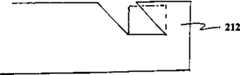
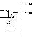
参见图13和14,在本发明的第八实施例中,便携式个人计算机211包括:通过元件214a、214b铰接在一起的第一翼212和第二翼213。这种布置使得当个人计算机不使用时,两翼212、213能够折叠在一起。第一翼包括相机单元215。Referring to Figures 13 and 14, in an eighth embodiment of the present invention, a portable personal computer 211 includes a
除了相机单元215被永久固定在第一翼213的主体内以外,这种个人计算机与图1中的个人计算机基本相同。相机单元包括:电荷耦合器件光传感器216,其设置在斜的通道217的底部。通道217相对于第一翼212倾斜大约40度。透镜218被设置在通道内以将光聚焦在电荷耦合器件216上。当相机单元215不使用时,可移动的插头219覆盖住通道的开口。This personal computer is substantially the same as the personal computer in FIG. 1 except that the camera unit 215 is permanently fixed within the body of the first wing 213 . The camera unit includes a charge-coupled
为了使得相机单元215更紧凑,轴217可以为“L”形,并在其拐弯处具有反射镜220。To make the camera unit 215 more compact, the
应该理解可以对上述实施例进行许多修改。It should be understood that many modifications may be made to the above-described embodiments.
例如,固定装置可以包括:设置在翼的前面的透明塑料片,使得文件可以在翼和透明塑料片之间滑动。For example, the securing means may comprise a transparent plastic sheet positioned in front of the wings such that the document can slide between the wing and the transparent plastic sheet.
不使用折下的单元,闪光单元可以被固定在计算机的翼内。Instead of using a fold-down unit, the flash unit can be secured inside the computer's wing.
可以使用LCD显示器的背光照射文件,而不使用闪光单元。Documents can be illuminated using the backlight of the LCD monitor instead of the flash unit.
文件放置的表面可以标出不同形状的文件的轮廓(例如,名片、A4、A5)以帮助对齐文件。The surface on which the documents rest can be outlined for documents of different shapes (eg business cards, A4, A5) to aid in document alignment.
可以使用机动变焦透镜代替固定的聚焦透镜。A motorized zoom lens can be used instead of a fixed focus lens.
可以使用三棱镜代替在“L”形轴的拐角处的透镜。Triangular prisms can be used instead of lenses at the corners of the "L" shaped axis.
Claims (12)
Translated fromChineseApplications Claiming Priority (2)
| Application Number | Priority Date | Filing Date | Title |
|---|---|---|---|
| GB9905384AGB2347813B (en) | 1999-03-09 | 1999-03-09 | Portable electronic apparatus |
| GB9905384.5 | 1999-03-09 |
Publications (1)
| Publication Number | Publication Date |
|---|---|
| CN1346456Atrue CN1346456A (en) | 2002-04-24 |
Family
ID=10849263
Family Applications (1)
| Application Number | Title | Priority Date | Filing Date |
|---|---|---|---|
| CN00806123APendingCN1346456A (en) | 1999-03-09 | 2000-01-25 | portable electronic device |
Country Status (12)
| Country | Link |
|---|---|
| EP (1) | EP1159666A1 (en) |
| JP (1) | JP2002539516A (en) |
| KR (1) | KR20010105380A (en) |
| CN (1) | CN1346456A (en) |
| AU (1) | AU3067500A (en) |
| BR (1) | BR0008839A (en) |
| CA (1) | CA2366849A1 (en) |
| GB (1) | GB2347813B (en) |
| HK (1) | HK1045578A1 (en) |
| ID (1) | ID30308A (en) |
| MX (1) | MXPA01009082A (en) |
| WO (1) | WO2000054129A1 (en) |
Cited By (7)
| Publication number | Priority date | Publication date | Assignee | Title |
|---|---|---|---|---|
| CN101393600B (en)* | 2007-09-21 | 2010-12-08 | 汉王科技股份有限公司 | Portable name card input device |
| CN101887290B (en)* | 2009-05-11 | 2011-11-16 | 致伸科技股份有限公司 | Notebook computer with file clamping function |
| CN101566866B (en)* | 2008-04-21 | 2011-11-23 | 株式会社Pfu | Notebook type information processor and image reading method |
| CN102298697A (en)* | 2010-06-23 | 2011-12-28 | 株式会社锦宫事务 | card information acquisition device |
| CN101102347B (en)* | 2006-03-24 | 2012-05-02 | 索尼株式会社 | Cellular Phones and Electronic Devices |
| CN107407854A (en)* | 2015-02-27 | 2017-11-28 | 日本电产科宝株式会社 | Blade drive |
| US10564515B2 (en) | 2015-02-27 | 2020-02-18 | Nidec Copal Corporation | Blade driving device |
Families Citing this family (9)
| Publication number | Priority date | Publication date | Assignee | Title |
|---|---|---|---|---|
| GB2373662B (en)* | 2001-01-23 | 2005-05-04 | Ash Technologies Res Ltd | A viewing device |
| AT501662B1 (en)* | 2001-02-07 | 2006-12-15 | Hoefler Kurt Mag Dipl Ing Dr | DEVICE FOR DIGITAL IMAGING AND STORAGE OF A DOCUMENT |
| TWM330797U (en)* | 2007-08-30 | 2008-04-21 | Aiptek Int Inc | Digital photo frame having photographing function |
| TWI372015B (en)* | 2009-04-17 | 2012-09-01 | Primax Electronics Ltd | Notebook computer with document holding function |
| JP2011076267A (en)* | 2009-09-29 | 2011-04-14 | Nec Personal Products Co Ltd | Information processing apparatus, material photographing method, program, and recording medium |
| JP5954158B2 (en)* | 2012-07-24 | 2016-07-20 | カシオ計算機株式会社 | Electronics |
| KR102040288B1 (en)* | 2013-02-27 | 2019-11-04 | 삼성전자주식회사 | Display apparatus |
| US11307620B2 (en) | 2017-04-17 | 2022-04-19 | Hewlett-Packard Development Company, L.P. | Camera system housing |
| TWD198214S (en)* | 2018-08-21 | 2019-06-21 | 宏碁股份有限公司 | Portable electronic device |
Family Cites Families (8)
| Publication number | Priority date | Publication date | Assignee | Title |
|---|---|---|---|---|
| DE2914998A1 (en)* | 1979-04-12 | 1980-10-23 | Alten K | TRANSFER BRIDGE FOR RAMPS |
| JPH04109353A (en)* | 1990-08-30 | 1992-04-10 | Toshiba Corp | Small computer provided with image reader |
| US5331434A (en)* | 1992-10-27 | 1994-07-19 | Cordata, Inc. | Integral computer scanning system |
| US5610730A (en)* | 1994-08-16 | 1997-03-11 | Osipchuk; Yuri V. | Low-cost high-resolution digital scanning camera |
| DE29510170U1 (en)* | 1995-06-22 | 1995-11-30 | Siemens AG, 80333 München | Pen-oriented small calculator in the form of a notepad |
| GB2307817B (en)* | 1995-12-01 | 1999-10-20 | Ibm | Display system with image scanning apparatus |
| JPH10164414A (en)* | 1996-12-03 | 1998-06-19 | Canon Inc | Notebook personal computer with built-in camera |
| US5801919A (en)* | 1997-04-04 | 1998-09-01 | Gateway 2000, Inc. | Adjustably mounted camera assembly for portable computers |
- 1999
- 1999-03-09GBGB9905384Apatent/GB2347813B/ennot_activeExpired - Fee Related
- 2000
- 2000-01-25IDIDW00200102158Apatent/ID30308A/enunknown
- 2000-01-25JPJP2000604290Apatent/JP2002539516A/ennot_activeWithdrawn
- 2000-01-25AUAU30675/00Apatent/AU3067500A/ennot_activeAbandoned
- 2000-01-25CACA002366849Apatent/CA2366849A1/ennot_activeAbandoned
- 2000-01-25KRKR1020017011444Apatent/KR20010105380A/ennot_activeWithdrawn
- 2000-01-25HKHK02106900.4Apatent/HK1045578A1/enunknown
- 2000-01-25BRBR0008839-0Apatent/BR0008839A/ennot_activeIP Right Cessation
- 2000-01-25WOPCT/GB2000/000198patent/WO2000054129A1/ennot_activeApplication Discontinuation
- 2000-01-25MXMXPA01009082Apatent/MXPA01009082A/enunknown
- 2000-01-25EPEP00900755Apatent/EP1159666A1/ennot_activeWithdrawn
- 2000-01-25CNCN00806123Apatent/CN1346456A/enactivePending
Cited By (9)
| Publication number | Priority date | Publication date | Assignee | Title |
|---|---|---|---|---|
| CN101102347B (en)* | 2006-03-24 | 2012-05-02 | 索尼株式会社 | Cellular Phones and Electronic Devices |
| CN101393600B (en)* | 2007-09-21 | 2010-12-08 | 汉王科技股份有限公司 | Portable name card input device |
| CN101566866B (en)* | 2008-04-21 | 2011-11-23 | 株式会社Pfu | Notebook type information processor and image reading method |
| CN101887290B (en)* | 2009-05-11 | 2011-11-16 | 致伸科技股份有限公司 | Notebook computer with file clamping function |
| CN102298697A (en)* | 2010-06-23 | 2011-12-28 | 株式会社锦宫事务 | card information acquisition device |
| CN107407854A (en)* | 2015-02-27 | 2017-11-28 | 日本电产科宝株式会社 | Blade drive |
| US10564515B2 (en) | 2015-02-27 | 2020-02-18 | Nidec Copal Corporation | Blade driving device |
| US10809595B2 (en) | 2015-02-27 | 2020-10-20 | Nidec Copal Corporation | Blade driving device |
| US11561456B2 (en) | 2015-02-27 | 2023-01-24 | Nidec Copal Corporation | Blade driving device for high resolution imaging apparatus |
Also Published As
| Publication number | Publication date |
|---|---|
| AU3067500A (en) | 2000-09-28 |
| JP2002539516A (en) | 2002-11-19 |
| ID30308A (en) | 2001-11-22 |
| GB2347813A (en) | 2000-09-13 |
| EP1159666A1 (en) | 2001-12-05 |
| WO2000054129A1 (en) | 2000-09-14 |
| GB2347813B (en) | 2001-02-21 |
| KR20010105380A (en) | 2001-11-28 |
| CA2366849A1 (en) | 2000-09-14 |
| GB9905384D0 (en) | 1999-05-05 |
| BR0008839A (en) | 2001-12-18 |
| HK1045578A1 (en) | 2002-11-29 |
| MXPA01009082A (en) | 2002-09-18 |
Similar Documents
| Publication | Publication Date | Title |
|---|---|---|
| CN1346456A (en) | portable electronic device | |
| US7561312B1 (en) | Systems and methods for glare removal using polarized filtering in document scanning | |
| CN1197329C (en) | Foldable information apparatus | |
| CN1214609C (en) | Display device having picture acquisition power and its use method | |
| JP3929437B2 (en) | Imaging auxiliary device and imaging method | |
| CN101171544A (en) | Accessories for magnification | |
| US20090167854A1 (en) | Apparatus For Converting Film Images Into Digital Data | |
| CN1645871A (en) | Mobile communication device with enhanced image communication capability | |
| TWI231050B (en) | Moveable mirror module for an image capturing apparatus capable of taking multi angle pictures | |
| CN1645910A (en) | Document camera and document camera system | |
| CN1577041A (en) | Image sensing apparatus | |
| US8781311B1 (en) | Document holder for a portable imaging apparatus | |
| CN1645873A (en) | Portable terminal device | |
| CN101512434B (en) | Portable Image Acquisition and Camera Device | |
| TW500971B (en) | Exposure control device for camera mounted on electronic apparatus | |
| US20090167853A1 (en) | Apparatus For Converting Film Images Into Digital Data | |
| CN1815345A (en) | Display amplifier device of digital camera | |
| CN113114819B (en) | Panoramic shooting method, electronic device and readable storage medium | |
| CN1438535A (en) | Automatic photography and camera device | |
| CN1610382A (en) | Digital image capture device capable of capturing images from different angles | |
| KR102096736B1 (en) | Photographing assistance device of portable device | |
| CN207304667U (en) | A kind of mobile phone photographic hand-held support | |
| JP3754699B2 (en) | Book scanner | |
| JPH1117886A (en) | Image reader | |
| JPH09233373A (en) | Image fetching device |
Legal Events
| Date | Code | Title | Description |
|---|---|---|---|
| C10 | Entry into substantive examination | ||
| SE01 | Entry into force of request for substantive examination | ||
| C06 | Publication | ||
| PB01 | Publication | ||
| C02 | Deemed withdrawal of patent application after publication (patent law 2001) | ||
| WD01 | Invention patent application deemed withdrawn after publication | ||
| REG | Reference to a national code | Ref country code:HK Ref legal event code:WD Ref document number:1045578 Country of ref document:HK |