CN1338031A - Ferroelectric pump - Google Patents
Ferroelectric pumpDownload PDFInfo
- Publication number
- CN1338031A CN1338031ACN98814353ACN98814353ACN1338031ACN 1338031 ACN1338031 ACN 1338031ACN 98814353 ACN98814353 ACN 98814353ACN 98814353 ACN98814353 ACN 98814353ACN 1338031 ACN1338031 ACN 1338031A
- Authority
- CN
- China
- Prior art keywords
- actuator
- contact
- planar surface
- voltage
- dome
- Prior art date
- Legal status (The legal status is an assumption and is not a legal conclusion. Google has not performed a legal analysis and makes no representation as to the accuracy of the status listed.)
- Pending
Links
Images


Classifications
- F—MECHANICAL ENGINEERING; LIGHTING; HEATING; WEAPONS; BLASTING
- F04—POSITIVE - DISPLACEMENT MACHINES FOR LIQUIDS; PUMPS FOR LIQUIDS OR ELASTIC FLUIDS
- F04B—POSITIVE-DISPLACEMENT MACHINES FOR LIQUIDS; PUMPS
- F04B43/00—Machines, pumps, or pumping installations having flexible working members
- F04B43/0009—Special features
- F04B43/0054—Special features particularities of the flexible members
- F—MECHANICAL ENGINEERING; LIGHTING; HEATING; WEAPONS; BLASTING
- F04—POSITIVE - DISPLACEMENT MACHINES FOR LIQUIDS; PUMPS FOR LIQUIDS OR ELASTIC FLUIDS
- F04B—POSITIVE-DISPLACEMENT MACHINES FOR LIQUIDS; PUMPS
- F04B43/00—Machines, pumps, or pumping installations having flexible working members
- F04B43/02—Machines, pumps, or pumping installations having flexible working members having plate-like flexible members, e.g. diaphragms
- F04B43/04—Pumps having electric drive
- F—MECHANICAL ENGINEERING; LIGHTING; HEATING; WEAPONS; BLASTING
- F04—POSITIVE - DISPLACEMENT MACHINES FOR LIQUIDS; PUMPS FOR LIQUIDS OR ELASTIC FLUIDS
- F04B—POSITIVE-DISPLACEMENT MACHINES FOR LIQUIDS; PUMPS
- F04B45/00—Pumps or pumping installations having flexible working members and specially adapted for elastic fluids
- F04B45/04—Pumps or pumping installations having flexible working members and specially adapted for elastic fluids having plate-like flexible members, e.g. diaphragms
- F04B45/047—Pumps having electric drive
- F—MECHANICAL ENGINEERING; LIGHTING; HEATING; WEAPONS; BLASTING
- F04—POSITIVE - DISPLACEMENT MACHINES FOR LIQUIDS; PUMPS FOR LIQUIDS OR ELASTIC FLUIDS
- F04B—POSITIVE-DISPLACEMENT MACHINES FOR LIQUIDS; PUMPS
- F04B53/00—Component parts, details or accessories not provided for in, or of interest apart from, groups F04B1/00 - F04B23/00 or F04B39/00 - F04B47/00
- F04B53/10—Valves; Arrangement of valves
- F—MECHANICAL ENGINEERING; LIGHTING; HEATING; WEAPONS; BLASTING
- F04—POSITIVE - DISPLACEMENT MACHINES FOR LIQUIDS; PUMPS FOR LIQUIDS OR ELASTIC FLUIDS
- F04B—POSITIVE-DISPLACEMENT MACHINES FOR LIQUIDS; PUMPS
- F04B53/00—Component parts, details or accessories not provided for in, or of interest apart from, groups F04B1/00 - F04B23/00 or F04B39/00 - F04B47/00
- F04B53/16—Casings; Cylinders; Cylinder liners or heads; Fluid connections
Landscapes
- Engineering & Computer Science (AREA)
- Mechanical Engineering (AREA)
- General Engineering & Computer Science (AREA)
- Reciprocating Pumps (AREA)
Abstract
Description
Translated fromChinese对相关申请的交叉引用Cross References to Related Applications
本申请与下述未获授权的相同申请人的PCT专利申请相关,申请号:__,于1998年_月_日提交,名称是“铁电流体流量控制阀”。本发明的由来This application is related to the following unauthorized PCT patent application by the same applicant, Application No. __, filed _month__1998, entitled "Ferroelectric Fluid Flow Control Valve". Origin of the invention
在此处描述的发明是美国政府职员研制的并且为实现政府目标可以进行免费的实施和使用。The inventions described herein were developed by United States Government employees and are freely available to make and use for government purposes.
本发明的背景技术Background Art of the Invention
本发明的技术领域Technical Field of the Invention
本发明涉及一种可用于液体和气体的泵,特别是一种利用一个或多个圆顶形的内预应力式铁电致动器的铁电泵,该铁电致动器的曲率和圆顶高度随施加在所述致动器内外表面间的电压而变化。The present invention relates to a pump usable for liquids and gases, in particular to a ferroelectric pump utilizing one or more dome-shaped internally prestressed ferroelectric actuators whose curvature and circular The peak height varies with the voltage applied between the inner and outer surfaces of the actuator.
相关技术的说明Description of related technologies
常规的泵通常可以分成两类:正排量泵和压力泵。压力泵沿着一个机械移动部分压迫一种介质,从而在该介质上产生一个压力。正排量泵作用于压缩物质的主体。实例包含一种往复式泵和一种风箱式泵。往复式泵通常使用一个位于活塞缸内的活塞以及一个用来提供活塞的机械运动的外部电源。风箱式泵通常包括一个由两个非变形的外部驱动端板以及在端板之间的一个可变形的膜片构成的泵体。Conventional pumps can generally be divided into two categories: positive displacement pumps and pressure pumps. Pressure pumps force a medium along a mechanically moving part, thereby creating a pressure on the medium. Positive displacement pumps act on a body of compressed material. Examples include a reciprocating pump and a bellows pump. Reciprocating pumps typically use a piston within a piston cylinder and an external power source to provide the mechanical movement of the piston. Bellows pumps generally consist of a pump body consisting of two non-deformable outer drive end plates with a deformable diaphragm between the end plates.
与铜线圈相关联的热损失和涡流电流的磁损失是降低使用运动机械部分的常规泵的效率的原因之一。如果有一种能够满足传统泵的流动速率和压力但可以减少热损失的泵将会是很有利的。减小尺寸和减低构造复杂性也是所希望的,这样可以降低制造成本。另外,运动机械零件数量的减少将降低磨损和污染并且增加可靠性。Heat losses associated with copper coils and magnetic losses from eddy currents are among the reasons that reduce the efficiency of conventional pumps that use moving mechanical parts. It would be advantageous to have a pump that could match the flow rates and pressures of conventional pumps but with reduced heat loss. Reduced size and reduced construction complexity are also desirable, which can reduce manufacturing costs. Additionally, the reduction in the number of moving mechanical parts will reduce wear and contamination and increase reliability.
很多现有的泵使用压电器件来替代常规的活塞、隔膜等等。两个压电部件的相互作用在美国专利第3,963,380和4,842,493号中被披露,Thomase等人的美国专利No.3963380号披露了一种微型泵,它有一个可变的容积室,由一个或两个市场上可买到的固定在装配环上的圆盘形弯片式压电换能器(disk bender)构成。该圆盘形弯片式压电换能器由一个用环氧树脂粘结到一个稍大的圆形黄铜垫块上的压电部件的薄片组成。当出现外加电压时,该压电薄片在其平面内沿直径方向膨胀或收缩。由于薄片被粘接到黄铜片上而使得薄片的圆周不能改变直径,因而由此产生了一个在中央膨胀形成球状表面的运动,Nilsson的第4,842493号美国专利披露了一种压电泵,其中压电部件被以这样一种方式安排,以使其长度、宽度和高度的变化协同产生所要求的泵排量。由于常规的小位移压电元件被使用,因此对于一个需要组合零件的复杂部件的泵就需要一个相对较长的泵槽来提供适当的泵容积。Many existing pumps use piezoelectric devices in place of conventional pistons, diaphragms, etc. The interaction of two piezoelectric components is disclosed in U.S. Patent Nos. 3,963,380 and 4,842,493, and U.S. Patent No. 3,963,380 to Thomas et al. discloses a micropump with a variable volume chamber composed of one or two A commercially available disk bender piezoelectric transducer (disk bender) fixed on the mounting ring. The disk-shaped bent-plate piezoelectric transducer consists of a thin slice of the piezoelectric component that is epoxy bonded to a slightly larger circular brass spacer. When an applied voltage is applied, the piezoelectric sheet expands or contracts diametrically within its plane. Since the foil is bonded to a brass sheet so that the circumference of the foil cannot change diameter, a motion is created that expands in the center to form a spherical surface. US Patent No. 4,842,493 to Nilsson discloses a piezoelectric pump, Therein the piezoelectric elements are arranged in such a manner that variations in their length, width and height cooperate to produce the desired pump displacement. Since conventional small displacement piezoelectric elements are used, a relatively long pump tank is required to provide adequate pump volume for a pump requiring a complex assembly of assembled parts.
可以确信的是在Okuyamae等人.的美国专利第4,939,405号中披露的概念仅仅适用于泵压一个小流体压头,比方说泵压被泵送的流体的微小背压。该概念还建立在通过将薄片悬挂在一个弹性膜片上并以谐振频率驱动该薄片来提高薄片的有限的振幅。上述概念的缺点是压力输出较小以及与这样的一个共振系统相关的小流体压头容量。该概念也需要一个组合零件的复杂部件。It is believed that the concept disclosed in US Patent No. 4,939,405 to Okuyamae et al. is only suitable for pumping a small fluid head, say a small back pressure of the fluid being pumped. The concept is also based on increasing the limited vibration amplitude of the foil by suspending it on an elastic diaphragm and driving the foil at a resonant frequency. The disadvantage of the above concept is the small pressure output and the small fluid head volume associated with such a resonant system. The concept also requires a complex assembly of parts.
美国专利第4,944,659和5,094,594号都使用了压电圆盘作为与泵的可变形室壁连接的一种变形装置。Abbe等人的美国专利第4,944,659号有关一种具有遥指命令控制逻辑电路的可植入式泵是可信的,这种泵针对一个小流体压头提供相对小流体量。泵是通过一个被粘贴到用来弯曲该压电盘的膜片上的压电圆盘来进行工作的。Brennan的美国专利第5,094,594号关于一种与电泳部件结合使用以便提供精确的高重复性的流体的微微升量级的泵。该可变容量室包括一个粘贴到一个较大的圆形垫块上的小压电部件薄片。因为被固定在圆盘上,所以薄片的圆周不能改变直径,从而,当外加电压存在时,由此产生的运动就是在中央部分的膨胀。US Patent Nos. 4,944,659 and 5,094,594 both use piezoelectric disks as a deformable device attached to the deformable chamber walls of the pump. US Patent No. 4,944,659 to Abbe et al. is credited with regard to an implantable pump with remote command control logic that provides a relatively small volume of fluid for a small fluid head. The pump works through a piezo disc that is glued to a diaphragm that bends the piezo disc. US Patent No. 5,094,594 to Brennan pertains to a picoliter pump used in conjunction with electrophoretic components to provide precise, highly repeatable fluid flow. The variable volume chamber consists of a thin sheet of piezoelectric component glued to a larger circular spacer. Being fixed to the disk, the circumference of the lamella cannot change diameter, so that when an applied voltage is present, the resulting motion is expansion in the central portion.
现有压电泵的缺点在于其较小的流动速率和压力能力。而且,它们通常需要一个组合零件的复杂部件。所以,就需要设计一种新的压电泵,该泵在保持现有压电泵的可靠性、运行效率、较小尺寸、以及较低成本的同时还能提供高于现有压电泵的流动速率和压力。同时也需要一种不用组合零件的复部件的压电泵。许多市场都能从这样的泵当中受益。它们可以被应用于军事和生物医学领域以及在喷墨印刷机和滴定程序当中。它们也可以被用来作燃料泵和小型供给泵。A disadvantage of existing piezoelectric pumps is their relatively small flow rates and pressure capabilities. Also, they often require a complex assembly of combined parts. Therefore, there is a need to design a new piezoelectric pump that can provide higher performance than existing piezoelectric pumps while maintaining the reliability, operating efficiency, smaller size, and lower cost of existing piezoelectric pumps. flow rate and pressure. There is also a need for a piezoelectric pump that does not require multiple parts to be assembled. Many markets could benefit from such pumps. They can be used in military and biomedical fields as well as in inkjet printers and titration procedures. They can also be used as fuel pumps and small feed pumps.
本发明的综述Summary of the invention
因此,本发明的一个目的是提供一种比现有压电泵尺寸小的泵,但在相同大小的情况下与现有压电泵相比可以保持或提高的流动速率和加压能力。Accordingly, it is an object of the present invention to provide a pump which is smaller in size than existing piezoelectric pumps, but which maintains or increases flow rate and pressurization capability compared to existing piezoelectric pumps at the same size.
另外一个目的是提供一种没有移动机械零件的泵。Another object is to provide a pump that has no moving mechanical parts.
本发明的另外一个目的是提供一种不需要有粘接构件的复杂部件的泵。Another object of the present invention is to provide a pump that does not require complex parts with adhesive components.
本发明的又一个目的是为了提供一种利用一个或多个圆顶形内预应力式铁电致动器的泵,每一个致动器都有一个随着外加在该致动器的内外表面之间的电压变化而变化的曲率和圆顶高度。Yet another object of the present invention is to provide a pump utilizing one or more dome-shaped internally prestressed ferroelectric actuators, each having a The curvature and dome height vary with voltage variation between.
本发明的再一个的目的是为了提供一种利用一个或多个圆顶形内预应力式铁电致动器的泵,每一个致动器都有一个随着外加在该致动器的内外表面之间的电压变化而变化的曲率和圆顶高度;每个致动器都有一个安装结构,将致动器与泵内介质隔离,还提供有用于将电压施加到该铁电致动器的路径,以及使铁电致动器能响应于外加电压而整个位移时也能确定地抑制(positively contain)铁电致动器。Yet another object of the present invention is to provide a pump utilizing one or more dome-shaped internally prestressed ferroelectric actuators, each actuator having a Varying curvature and dome height as a function of the voltage between the surfaces; each actuator has a mounting structure that isolates the actuator from the pump media and provides a means for applying voltage to the ferroelectric actuator path, and also positively contain the ferroelectric actuator while enabling its entire displacement in response to an applied voltage.
本发明的另外一个目的是提供单向连续的泵压液体和气体的泵。Another object of the present invention is to provide a pump for unidirectional continuous pumping of liquids and gases.
还有一个目的是提供一种能够对气体进行周期性压缩的泵。Yet another object is to provide a pump capable of periodically compressing gas.
本发明的其他目的和优点将在后续的附图和说明书中体现出来。Other objects and advantages of the present invention will appear in the subsequent drawings and descriptions.
本发明的概述Summary of the invention
根据本发明,上述以及其他的发明目的和优点可以通过提供一种铁电泵来实现,该泵利用一个或多个圆顶形内预应力式铁电致动器,每一个致动器都有一个随着施加在该致动器的内外表面之间的电压变化而变化的曲率和圆顶高度。这种泵具体体现了铁电设备也可以作为一个整体并且事实成为流体泵机械的主要部件,而在以往其仅仅被视为是一种从电能转换成机械运动的变换器而已。本发明不同于往复式泵,其区别在于是铁电致动器本身执行了活塞和活塞缸的功能。另外“活塞”上的运动机械力是整体产生于该铁电设备的内部,而不是外加的。该泵也不同于风箱式泵,将端部板以及变形模片和机械移动件都集中到一个简单的单一部件中,也就是该铁电致动器。According to the present invention, the foregoing and other inventive objects and advantages are achieved by providing a ferroelectric pump utilizing one or more dome-shaped internally prestressed ferroelectric actuators, each having a A curvature and dome height that vary with the voltage applied between the inner and outer surfaces of the actuator. This pump embodies that ferroelectric devices can also be taken as a whole and in fact become a major part of fluid pump machinery, which was previously considered only a converter from electrical energy to mechanical motion. The present invention differs from reciprocating pumps in that the ferroelectric actuator itself performs the functions of the piston and cylinder. In addition, the moving mechanical force on the "piston" is entirely generated inside the ferroelectric device, rather than externally applied. The pump also differs from bellows pumps in that the end plates as well as the deforming dies and mechanical moving parts are concentrated into a simple single component, the ferroelectric actuator.
该泵在一个外壳内有一个或者多个可变容量的增压室(pumpingchamber)。每个增压室有至少一个包含有随着外加在该致动器的内外表面之间的电压变化而变化的曲率和圆顶高度的圆顶形内预应力式致动器的壁。泵压的媒质响应于该铁电致动器的位移而流入和流出每一个泵室。铁电致动器被安装到每一个壁内,并将每一个铁电致动器与泵压的媒质隔离开,还为每个铁电致动器提供一条施加电压的路径,以及给每个铁电致动器提供确定抑制同时使每个铁电致动器能响应于外加电压而完全位移。The pump has one or more variable volume pumping chambers within a housing. Each plenum has at least one wall containing a dome-shaped internally prestressed actuator having a curvature and dome height that vary in response to a voltage applied between the inner and outer surfaces of the actuator. Pumped medium flows into and out of each pump chamber in response to displacement of the ferroelectric actuator. Ferroelectric actuators are mounted within each wall, isolating each ferroelectric actuator from the pumped medium, and providing a path for each ferroelectric actuator to apply a voltage, and to each The ferroelectric actuators provide deterministic suppression while enabling full displacement of each ferroelectric actuator in response to an applied voltage.
附图的简要说明Brief description of the drawings
对本发明以及其大量优点将通过参照下列附图而进行的详细说明被更好地领会和理解,这些附图包括:The present invention, together with its numerous advantages, will be better appreciated and understood with reference to the detailed description that follows with reference to the accompanying drawings, which include:
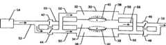
图1是一个有三个增压室的实施例示意图。Figure 1 is a schematic diagram of an embodiment having three plenums.
图2是一个有阀门的单室泵。Figure 2 is a single chamber pump with valves.
图3是一个有流体阀门的单室泵。Figure 3 is a single chamber pump with fluid valves.
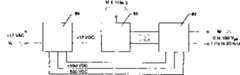
图4是一个表示用于提供正弦变化的电压波形的适当的电子电路示意图。Figure 4 is a schematic diagram showing a suitable electronic circuit for providing a sinusoidally varying voltage waveform.
图5是一个表示用于提供以固定频率正弦变化的电压波形的适当的电子电路示意图,Figure 5 is a schematic diagram showing a suitable electronic circuit for providing a voltage waveform varying sinusoidally at a fixed frequency,
图6是该铁电致动器装置的分解图。Fig. 6 is an exploded view of the ferroelectric actuator device.
图7是一个电接接触环。Figure 7 is an electrical contact ring.
优选实施例的详细说明Detailed Description of the Preferred Embodiment
本发明的第一个实施例如图1所示,是一个三室泵。泵壳体30围住三个增压室32、34、36。所要求的多个增压室并且至少一个可以被使用。每个增压室有至少一个壁38,该壁包含一个圆顶形的内预应力式铁电致动器40、它的曲率和圆顶高度随着施加在该致动器的内外表面之间的电压变化而变化。这样的致动器实例在美国专利第5,471,721号“制造整体预应力陶瓷设备的方法”中被披露,并在此作为参考,通常可以从辉光陶瓷学(Arua Ceramics)中得到,在美国专利第5,632,841号“薄层合成单结构铁电驱动器和传感器”中也提到了,这里也列作参考。加在铁电致动器上的电压在制动器的两面之间产生一个电场,并且引起该致动器形状的变化。该致动器将根据所加电场的极性变平或升高。这类铁电致动器固有地显示出在机械运动的量程和输出力量程之间的平衡。铁电致动器的尺寸选择、以及所加电压和频率,共同确定了运动和产生压力的具体值。这些铁电致动器可以产生百分之几百的应变并且能够承受至少十磅的载荷。该泵的工作能力能通过在一个通用集流腔内使用多个铁电致动器来进一步提高。一对致动器按照蚌式边对边的叠放就可以获得两倍大的工作能力。如果需要更大的工作能力的话,好几个这种蚌式装置可以串联起来。这样的装置在美国专利第5,471,721号“制造整体预应力陶瓷设备的方法”和美国专利第5,632,841号“薄层合成单一结构铁电驱动器和传感器”中都提到过。A first embodiment of the invention, shown in Figure 1, is a three-chamber pump. The
该致动器的驱动电压可以是任何波形的,当然正弦式的是较好的。在正弦波驱动电压的正半周期内,该致动器彼此相向运动,阀门44和46打开而阀门42和48闭合。液体流入部件32和36并且流出部件34。在该正弦波驱动电压的负半周期内,致动器彼此相背运动。阀门44和46现在闭合而阀门42和48打开。液体流入部件34并且流出部件32和36。来自泵压媒质源54的泵压媒质是通过入口流管50流入到每一个室里的。一个泵压的媒质供给入口52被连接到泵压的媒质源54上。那些位于每个室入口处的室供给入口50是供给入口52的接口(interfaced)。该泵压媒质通过出口流管56流出室。位于供给入口52和内腔入口50之间的单向液流阀门42和44响应于该致动器使泵压媒质进入到每一个增压室中同时防止泵压媒质的回流。出口的结构类似于入口,具有一个室排放出口、一个媒质排放出口和单向液流阀46和48。在图1所示的结构中,增压室32和36的容积处于减小状态从而将泵压媒质向外排。阀门44防止了当增压室32和36的体积减小时候产生的回流,同时阀门48允许来自容积减小的增压室的液流排出。增压室34的容积在图示状态下是增大的,从而液流进入该室。阀门42打开以允许泵压媒质进入增压室34内而阀门46关闭以防止泵压媒质的回流。增压室和液流阀门以及管系的构造种类很多。图1所示的仅仅是这些构造当中的一种。单室的可以被使用或多于三室的也可以使用。无论常规阀门或者铁电阀门都可以使用,如于1998年4月提交的PCT专利申请第__号,“铁电流体流量控制阀”中提到的铁电阀门也可以用,这里列出以供参考。阀门的布置也可以是任何适当的形式。例如,入口和出口阀门可以被设置在增压室的两个相对侧或是相同的一侧。一个简单的单室泵如图2所示,其工作过程与前述的三室泵大体相当。泵压媒质通过阀门62在入口60处流入并且通过阀门72在出口70处流出。增压室64由两个铁电致动器66构成。密封件68和阀门62和72可以是任何可能的排列方式。一个孔口74可以用来防止在致动器66的运动过程中造成的负压。图3也显示了一个单室泵的实施例,然而,本实施例使用了一个流体阀门构造76,从而避免了任何运动的部件。孔77的直径小于阀门出口78的直径。容积室79是圆柱形的。泵压媒质通过入口75进入然后通过孔77进入增压室64。从孔77流出出口78外的泵压媒质液流由于液流成雾沫状被带走而有一个速度矢量,这样的速度矢量和液流的雾沫在入口75是不存在的。The driving voltage of the actuator can be of any waveform, of course, the sinusoidal one is better. During the positive half cycle of the sine wave drive voltage, the actuators move toward each other with
当电压被加到致动器上的时候,每个致动器都会发生位移。通过控制这个变化电压的振幅和频率,泵的运行以及泵流速率都可以受到控制。流动速率可以在最大流率的百分之几到最大流率之间的范围内以很高的精度调节。图4是一个用于提供正弦变化电压波形的适当的电子逻辑电路方框图。该电路包括一个产生使泵运行的正弦波的波形发生器80、一个根据致动器的需要将电压和电流放大到所需大小的电压放大器82和一个为波形发生器80和电压放大器82提供直流电压的直流电源84。这个电路能够提供峰峰值最大为1000伏、频率范围从1Hz到20kHz的正弦波输出电压和几百毫安的电流。对于波形发生器80,一种专门的集成电路芯片,如XR2206,带有少数的附加电阻、电容和电位器,可以产生所需要的正弦波形,其幅度从0到峰峰值为6伏、频率从1Hz到20kHz.之间变化。这个低能级正弦波信号被连接到固定增益电压放大器82的输入端,该放大器能提供的电压幅度的放大最大为200倍。一个实用的放大器设计采用两个以推挽式构造连接的高电压运算放大器,它能提供单一运算放大器两倍的输出。对于该电路的设计,高压运算放大器可以选择高电压中等电流输出或中等电压高电流输出。适当的推挽式电路结构采用两个由Apex Microtechnolagy公司制造的Apex PA89运算放大器,加上少数几个外部元件很容易做成,以提供推动致动器所需的电压和电流。直流电源为波形发生器80和放大器电路82提供直流电压。标准电源为波形发生器和放大器电路提供12V的直流电。两个直流-直流转换器将12Vdc放大成为放大器电路中的高电压运算放大器所需要的+500和-500Vdc。Each actuator is displaced when voltage is applied to the actuator. By controlling the amplitude and frequency of this varying voltage, the operation of the pump as well as the pump flow rate can be controlled. The flow rate can be adjusted with high precision in the range between a few percent of the maximum flow rate and the maximum flow rate. Figure 4 is a block diagram of a suitable electronic logic circuit for providing a sinusoidally varying voltage waveform. The circuit consists of a
在图5中示出了另外一个适当的电子电路,它以固定的60Hz的频率提供一个正弦变化电压。它包括一个可变比变压器90,其输入可连接到任何标准的117Vac的电源上。为了操作人员的安全,该可变比变压器90的输出可连接到一个1∶1转化比的隔离变压器92上。该变压器92的输出连在电源的其余两个部分上。一部分是一个全波桥式整流器94,它包括一用于在电子电路的输出端提供正直流偏压的滤波器电容器96。另外一个部分是一个升压变压器98,用于提供致动器所需的更高的电压。该升压变压器98的输出被串联到正直流偏压上。通过适当选择升变压器98和调整可变比变压器90的控制,这个电路提供的输出电压可以从0到1000伏的峰峰值。由于正直流偏压,典型的电压最大输出是峰值+600伏和峰值-400伏。响应电压值较高的正压高是致动器的固有性质。因此,为了使致动器发生最大位移,需要使用正直流偏压。Another suitable electronic circuit is shown in Figure 5, which supplies a sinusoidally varying voltage at a fixed frequency of 60 Hz. It includes a variable ratio transformer 90 whose input can be connected to any standard 117Vac power source. For operator safety, the output of the variable ratio transformer 90 can be connected to an isolation transformer 92 with a conversion ratio of 1:1. The output of this transformer 92 is connected to the remaining two sections of the power supply. One part is a full wave bridge rectifier 94 which includes a filter capacitor 96 for providing a positive DC bias at the output of the electronic circuit. The other part is a step-up transformer 98 to provide the higher voltage required by the actuator. The output of the step-up transformer 98 is connected in series to the positive DC bias. By proper selection of the step-up transformer 98 and adjustment of the control of the variable ratio transformer 90, this circuit can provide an output voltage from 0 to 1000 volts peak-to-peak. Typical voltage maximum output is +600 volts peak and -400 volts peak due to positive DC bias. It is an inherent property of the actuator to respond to positive voltages with higher voltage values. Therefore, for maximum displacement of the actuator, a positive DC bias is required.
致动器被如此安装以使安装构造能让每一个致动器都与泵压媒质隔离,还为施加在每个致动器外加电压提供一条路径,以及在允许每个致动器响应于外加电压完全位移的同时为每个致动器提供确定的抑制。图6是泵壳体与增压室的一个实施例的分解图。一个绝缘泵壳体100围住三个增压室102、104、和106。一个壁组件在每一个室之间构成一隔壁。每个壁由两个密封垫108、两个电绝缘体110、两个电接接触环112、一个致动器垫片114、以及一个致动器116组成。垫片114与致动器116的厚度最好相同。致动器116在垫片114的内部被如此定位以使致动器116的周边与垫片114的内周边相接触。电接接触环112被定位在垫片114的每个侧面与垫片114接触并且为致动器116提供电接触。一个电绝缘体110位于各个接接触环112的外表面与接接触环112接触并且与致动器116同心。绝缘体110应该与泵压媒质,例如乳液。能共处并且有一定弹性。一种非导电液体,如硅液体,被用在致动器116和绝缘体110之间。该液体对其他材料应该具有化学稳定性并且还要有一定的粘性以便将绝缘体110和致动器116保持相对固定。这样就消除了气袋从而提高了效率和容量。一个具有一个与接触环112孔同心的孔的密封垫108被定位在紧靠每个绝缘体110。该密封垫108由诸如橡胶这样的绝缘材料制成。壁装置用一种诸如定位螺丝的紧固件连接在壳体部件之间。所需的固紧力仅仅是将其保持在适当位置所需力的最小值。不需要预压力了。The actuators are mounted such that the mounting configuration isolates each actuator from the pumped medium, provides a path for an applied voltage to be applied to each actuator, and allows each actuator to respond to the applied voltage. The voltage provides defined damping for each actuator while fully displacing. Figure 6 is an exploded view of one embodiment of the pump housing and pumping chamber. An insulating
该装置并不限制致动器的的任何数量、厚度或大小。每个具体的应用都应当考虑该装置的部件参数,例如,致动器位移的量和致动器力的大小。The device does not limit any number, thickness or size of the actuators. Each specific application should take into account the component parameters of the device, eg, the amount of actuator displacement and the magnitude of the actuator force.
一根电源引线118经外壳100上的一个钻孔进入外壳100内。该导线118与一个置于外壳100上的定位螺丝弹簧120接触。该定位螺丝120与电接接触环112接触以便为该环112提供外加电压。该接接触环112与垫片和致动器的一部分重叠。如图7所示,接触环112有一部分130与致动器重叠,它是一个诸如铝箔这样的导电体。与致动器接触的环的外部132是带有一个与调节螺钉弹簧接触的导电部分134的非导电材料。胶纸带是合适的非导电材料的一个实例。虽然圆形的致动器和其他配套的圆形装配零件是首选的,但是其他形状也是可以的。A
外加在致动器上的正负电压级将随厚度,随过高电压产生的电弧而变化。The positive and negative voltage levels applied to the actuator will vary with thickness and with arcing from excess voltage.
泵的效率和功率还能够通过使用能够使用高频响应的阀门来进一步提高。如果诸如这里引入供参考的PCT专利申请第___号,于1998年四月提交的“铁电流体液流控制阀门”中提到的铁电阀门被使用的话,流体液流功率将会成倍提高。The efficiency and power of the pump can be further improved by using valves capable of using high frequency response. If a ferroelectric valve such as that mentioned in PCT Patent Application No. ___, filed April 1998, "Ferroelectric Fluid Flow Control Valve" is used, the fluid flow power will be doubled improve.
与常规排量泵对比,由于不使用机械可动部件而使得本发明的泵具有更高的可靠性和更低的成本。本发明的泵也具有高于常规泵的机械效率。现有装置中与镀铜线圈相关联的热损失以及来自涡流电流的磁损失现在都完全避免了。相对于现有压电泵,由于不需要进行很多压电盘之间的搭接/组装,本发明的泵也就具有了更高的可靠性,更低的成本,较低的复杂性,以及较小的尺寸。目前只有通过压电盘装置才能获得的相同的压力和排量也能够得到了。另外,该装置构造允许响应于外加电压的每个致动器的完全位移。Compared with conventional displacement pumps, the pump of the present invention has higher reliability and lower cost due to the absence of mechanical moving parts. The pump of the present invention also has a higher mechanical efficiency than conventional pumps. The thermal losses associated with copper-plated coils in existing devices as well as magnetic losses from eddy currents are now completely avoided. Compared with existing piezoelectric pumps, the pump of the present invention has higher reliability, lower cost, lower complexity, and smaller size. The same pressures and displacements that are currently only available with piezoelectric disc devices are also available. Additionally, the device configuration allows for full displacement of each actuator in response to an applied voltage.
显然,根据上面给出的技术教导,很多对本发明的附加限定和改进都是可能的。因此可以理解的是,在不脱离下述权利要求的范围内,本发明可以不按照此处的具体限定形式进行实施。Obviously, many additional limitations and modifications of the invention are possible in light of the technical teaching given above. It is therefore to be understood that, without departing from the scope of the following claims, the invention may be practiced otherwise than as specifically limited herein.
Claims (14)
Translated fromChineseApplications Claiming Priority (1)
| Application Number | Priority Date | Filing Date | Title |
|---|---|---|---|
| PCT/US1998/026389WO2000036302A1 (en) | 1998-12-11 | 1998-12-11 | Ferroelectric pump |
Publications (1)
| Publication Number | Publication Date |
|---|---|
| CN1338031Atrue CN1338031A (en) | 2002-02-27 |
Family
ID=22268467
Family Applications (1)
| Application Number | Title | Priority Date | Filing Date |
|---|---|---|---|
| CN98814353APendingCN1338031A (en) | 1998-12-11 | 1998-12-11 | Ferroelectric pump |
Country Status (8)
| Country | Link |
|---|---|
| EP (1) | EP1137884A1 (en) |
| JP (1) | JP2002532655A (en) |
| KR (1) | KR20010108015A (en) |
| CN (1) | CN1338031A (en) |
| AU (1) | AU2199599A (en) |
| CA (1) | CA2354076A1 (en) |
| NO (1) | NO20012845L (en) |
| WO (1) | WO2000036302A1 (en) |
Cited By (4)
| Publication number | Priority date | Publication date | Assignee | Title |
|---|---|---|---|---|
| CN101328879B (en)* | 2008-05-23 | 2010-06-23 | 北京联合大学 | Valve and vibrator integrated piezoelectric pump with valve |
| CN101680873B (en)* | 2007-04-04 | 2015-11-25 | 加利福尼亚大学董事会 | Compositions, devices, systems and methods using nanopores |
| CN106536930A (en)* | 2014-02-28 | 2017-03-22 | 斯蒂芬.A.马什 | micropump system |
| US10330095B2 (en) | 2014-10-31 | 2019-06-25 | Encite Llc | Microelectromechanical systems fabricated with roll to roll processing |
Families Citing this family (5)
| Publication number | Priority date | Publication date | Assignee | Title |
|---|---|---|---|---|
| US7147955B2 (en)* | 2003-01-31 | 2006-12-12 | Societe Bic | Fuel cartridge for fuel cells |
| DE102006016571B4 (en)* | 2006-04-06 | 2008-09-04 | Bartels Mikrotechnik Gmbh | Method and device for the automated conveyance of liquids or gases |
| FR2929450B1 (en)* | 2008-03-28 | 2010-08-20 | Seb Sa | HOUSEHOLD APPLIANCE COMPRISING A PIEZOELECTRIC PUMP WITH A SIMPLIFIED ELECTRIC POWER SUPPLY CIRCUIT |
| ES2716964T3 (en)* | 2014-10-13 | 2019-06-18 | Alfa Srl | Volumetric pump and pumping group for fluid products and their method of use |
| US10563642B2 (en)* | 2016-06-20 | 2020-02-18 | The Regents Of The University Of Michigan | Modular stacked variable-compression micropump and method of making same |
Family Cites Families (12)
| Publication number | Priority date | Publication date | Assignee | Title |
|---|---|---|---|---|
| US3963380A (en) | 1975-01-06 | 1976-06-15 | Thomas Jr Lyell J | Micro pump powered by piezoelectric disk benders |
| EP0268204B1 (en) | 1986-11-14 | 1991-09-18 | Qenico AB | Piezoelectric pump |
| GB8701731D0 (en) | 1987-01-27 | 1987-03-04 | Patcentre Benelux Nv Sa | Pumps |
| JPH01174278A (en) | 1987-12-28 | 1989-07-10 | Misuzu Erii:Kk | Inverter |
| DE4006152A1 (en)* | 1990-02-27 | 1991-08-29 | Fraunhofer Ges Forschung | MICROMINIATURIZED PUMP |
| US5094594A (en) | 1990-04-23 | 1992-03-10 | Genomyx, Incorporated | Piezoelectric pumping device |
| GB2248891A (en)* | 1990-10-18 | 1992-04-22 | Westonbridge Int Ltd | Membrane micropump |
| US5471721A (en) | 1993-02-23 | 1995-12-05 | Research Corporation Technologies, Inc. | Method for making monolithic prestressed ceramic devices |
| DE69431994T2 (en)* | 1993-10-04 | 2003-10-30 | Res Int Inc | MICRO-MACHINED FLUID TREATMENT DEVICE WITH FILTER AND CONTROL VALVE |
| US5802195A (en)* | 1994-10-11 | 1998-09-01 | The United States Of America As Represented By The Administrator Of The National Aeronautics And Space Administration | High displacement solid state ferroelectric loudspeaker |
| FR2727474B1 (en)* | 1994-11-25 | 1997-01-10 | Centre Nat Rech Scient | INTEGRATED ELECTRIC DISCHARGE MICRO ACTUATOR AND MICROSYSTEM COMPRISING THIS MICRO ACTUATOR |
| US5632841A (en) | 1995-04-04 | 1997-05-27 | The United States Of America As Represented By The Administrator Of The National Aeronautics And Space Administration | Thin layer composite unimorph ferroelectric driver and sensor |
- 1998
- 1998-12-11JPJP2000588515Apatent/JP2002532655A/ennot_activeWithdrawn
- 1998-12-11WOPCT/US1998/026389patent/WO2000036302A1/ennot_activeApplication Discontinuation
- 1998-12-11EPEP98965990Apatent/EP1137884A1/ennot_activeWithdrawn
- 1998-12-11AUAU21995/99Apatent/AU2199599A/ennot_activeAbandoned
- 1998-12-11CNCN98814353Apatent/CN1338031A/enactivePending
- 1998-12-11KRKR1020017007298Apatent/KR20010108015A/ennot_activeWithdrawn
- 1998-12-11CACA002354076Apatent/CA2354076A1/ennot_activeAbandoned
- 2001
- 2001-06-08NONO20012845Apatent/NO20012845L/ennot_activeApplication Discontinuation
Cited By (7)
| Publication number | Priority date | Publication date | Assignee | Title |
|---|---|---|---|---|
| CN101680873B (en)* | 2007-04-04 | 2015-11-25 | 加利福尼亚大学董事会 | Compositions, devices, systems and methods using nanopores |
| CN101328879B (en)* | 2008-05-23 | 2010-06-23 | 北京联合大学 | Valve and vibrator integrated piezoelectric pump with valve |
| CN106536930A (en)* | 2014-02-28 | 2017-03-22 | 斯蒂芬.A.马什 | micropump system |
| US10344753B2 (en) | 2014-02-28 | 2019-07-09 | Encite Llc | Micro pump systems |
| CN106536930B (en)* | 2014-02-28 | 2020-03-27 | 斯蒂芬.A.马什 | Micropump system |
| US11525441B2 (en) | 2014-02-28 | 2022-12-13 | Encite Llc | Airway pressure device with micro-pump system |
| US10330095B2 (en) | 2014-10-31 | 2019-06-25 | Encite Llc | Microelectromechanical systems fabricated with roll to roll processing |
Also Published As
| Publication number | Publication date |
|---|---|
| AU2199599A (en) | 2000-07-03 |
| WO2000036302A1 (en) | 2000-06-22 |
| EP1137884A1 (en) | 2001-10-04 |
| KR20010108015A (en) | 2001-12-07 |
| JP2002532655A (en) | 2002-10-02 |
| CA2354076A1 (en) | 2000-06-22 |
| NO20012845D0 (en) | 2001-06-08 |
| NO20012845L (en) | 2001-08-07 |
Similar Documents
| Publication | Publication Date | Title |
|---|---|---|
| US6071087A (en) | Ferroelectric pump | |
| US9217426B2 (en) | Pump, pump arrangement and pump module | |
| AU2004201810A1 (en) | Ferroelectric pump | |
| US7320457B2 (en) | Electroactive polymer devices for controlling fluid flow | |
| US7703742B2 (en) | Electroactive polymer devices for controlling fluid flow | |
| US6869275B2 (en) | Piezoelectrically driven fluids pump and piezoelectric fluid valve | |
| CN101115924A (en) | Reaction-driven energy transmission device | |
| CN1338031A (en) | Ferroelectric pump | |
| CA2470657C (en) | Multi pumping chamber magnetostrictive pump | |
| US6604915B1 (en) | Compact, high efficiency, smart material actuated hydraulic pump | |
| US20200191094A1 (en) | Power driver of unmanned aerial vehicle | |
| CN113638935B (en) | Electrostatic actuator driven by magnetostrictive axial four-piston pump and its working method | |
| CN113090610B (en) | Surface mount type piezoelectric screw pump hydraulic linear actuator and driving method thereof | |
| Jalink Jr et al. | Ferroelectric Pump | |
| MXPA01005911A (en) | Ferroelectric pump | |
| CN1125921C (en) | Ferroelectric fluid flow control valve | |
| CN109882387B (en) | A piezoelectric gas pump | |
| CN109812454B (en) | A self-propelled cylinder | |
| CN204738948U (en) | A Sandwich Type Longitudinal-Torsion Compound Vibration Active Water Jet Propulsion Device | |
| CN204755271U (en) | Indulge sandwich active type water -jet propulsion system that shakes | |
| CN110094384B (en) | Self-air-supply cylinder | |
| CN109931250B (en) | Series cavity array type micro piezoelectric gas compressor | |
| US20060269427A1 (en) | Miniaturized diaphragm pump with non-resilient seals | |
| CN119737484A (en) | A triboelectric self-sensing piezoelectric microvalve and flow monitoring method | |
| CN120312563A (en) | A small resonant piezoelectric stack pump |
Legal Events
| Date | Code | Title | Description |
|---|---|---|---|
| C06 | Publication | ||
| PB01 | Publication | ||
| C10 | Entry into substantive examination | ||
| SE01 | Entry into force of request for substantive examination | ||
| AD01 | Patent right deemed abandoned | ||
| C20 | Patent right or utility model deemed to be abandoned or is abandoned |