CN1327410C - Code conversion method and device between speech codec methods - Google Patents
Code conversion method and device between speech codec methodsDownload PDFInfo
- Publication number
- CN1327410C CN1327410CCNB038176750ACN03817675ACN1327410CCN 1327410 CCN1327410 CCN 1327410CCN B038176750 ACNB038176750 ACN B038176750ACN 03817675 ACN03817675 ACN 03817675ACN 1327410 CCN1327410 CCN 1327410C
- Authority
- CN
- China
- Prior art keywords
- gain
- code
- acb
- circuit
- fcb
- Prior art date
- Legal status (The legal status is an assumption and is not a legal conclusion. Google has not performed a legal analysis and makes no representation as to the accuracy of the status listed.)
- Expired - Fee Related
Links
Images


Classifications
- G—PHYSICS
- G10—MUSICAL INSTRUMENTS; ACOUSTICS
- G10L—SPEECH ANALYSIS TECHNIQUES OR SPEECH SYNTHESIS; SPEECH RECOGNITION; SPEECH OR VOICE PROCESSING TECHNIQUES; SPEECH OR AUDIO CODING OR DECODING
- G10L19/00—Speech or audio signals analysis-synthesis techniques for redundancy reduction, e.g. in vocoders; Coding or decoding of speech or audio signals, using source filter models or psychoacoustic analysis
- G10L19/04—Speech or audio signals analysis-synthesis techniques for redundancy reduction, e.g. in vocoders; Coding or decoding of speech or audio signals, using source filter models or psychoacoustic analysis using predictive techniques
- G10L19/08—Determination or coding of the excitation function; Determination or coding of the long-term prediction parameters
- G10L19/083—Determination or coding of the excitation function; Determination or coding of the long-term prediction parameters the excitation function being an excitation gain
- G—PHYSICS
- G10—MUSICAL INSTRUMENTS; ACOUSTICS
- G10L—SPEECH ANALYSIS TECHNIQUES OR SPEECH SYNTHESIS; SPEECH RECOGNITION; SPEECH OR VOICE PROCESSING TECHNIQUES; SPEECH OR AUDIO CODING OR DECODING
- G10L19/00—Speech or audio signals analysis-synthesis techniques for redundancy reduction, e.g. in vocoders; Coding or decoding of speech or audio signals, using source filter models or psychoacoustic analysis
- G10L19/04—Speech or audio signals analysis-synthesis techniques for redundancy reduction, e.g. in vocoders; Coding or decoding of speech or audio signals, using source filter models or psychoacoustic analysis using predictive techniques
- G10L19/08—Determination or coding of the excitation function; Determination or coding of the long-term prediction parameters
- G10L19/12—Determination or coding of the excitation function; Determination or coding of the long-term prediction parameters the excitation function being a code excitation, e.g. in code excited linear prediction [CELP] vocoders
Landscapes
- Engineering & Computer Science (AREA)
- Computational Linguistics (AREA)
- Signal Processing (AREA)
- Health & Medical Sciences (AREA)
- Audiology, Speech & Language Pathology (AREA)
- Human Computer Interaction (AREA)
- Physics & Mathematics (AREA)
- Acoustics & Sound (AREA)
- Multimedia (AREA)
- Compression, Expansion, Code Conversion, And Decoders (AREA)
Abstract
Description
Translated fromChinese技术领域technical field
本发明涉及一种用于以低码率传输或存储语音信号的编码及解码方法,特别是涉及一种在使用不同的编解码方法进行语音通信时,将使用某种方法对语音进行编码而得的代码以高音质和低运算量转换成能够以其他方法进行解码的代码的代码转换方法及装置及其存储介质。The present invention relates to a coding and decoding method for transmitting or storing speech signals at a low bit rate, and in particular to a method for coding speech using a certain method when using different codec methods for speech communication. A code conversion method and device for converting codes that can be decoded by other methods with high sound quality and low calculation load, and a storage medium thereof.
背景技术Background technique
作为以低码率且高效地对语音信号进行编码的方法,广泛使用着将语音信号分离成线性预测(Linear Prediction:IP)滤波器和驱动它的激励信号来进行编码的方法。作为其具有代表性的方法之一,有码激励线性预测(Code Excited Linear Prediction:称为CELP)。在CELP中,通过使用激励信号驱动LP滤波器来得到合成语音信号,其中所述LP滤波器设定有表示输入语音的频率特性的LP系数,所述激励信号用表示输入语音的间隔(pitch)周期的自适应码本(Adaptive Codebook:称为ACB)和由随机数或脉冲组成的固定码本(Fixed Codebook:称为FCB)之和来表示。此时,在所述ACB成分和所述FCB成分上乘上各自的增益(“ACB增益”和“FCB增益”)。此外,关于CELP,可参见M.Schroeder和S.Atal的《Code excited linear prediction:High quality speech at very low bit rates》(Proc.Of IEEE Int.Conf.On Acoust.,Speech and Signal Processing,pp.937-940,1985)(称为文献1)。As a method of efficiently encoding speech signals at a low bit rate, a method of encoding speech signals by separating them into a linear prediction (Linear Prediction: IP) filter and an excitation signal that drives it is widely used. As one of its representative methods, Code Excited Linear Prediction (Code Excited Linear Prediction: called CELP). In CELP, a synthesized speech signal is obtained by driving an LP filter with an excitation signal that is set with an LP coefficient representing the frequency characteristic of the input speech, and the excitation signal is represented by an interval (pitch) of the input speech. It is represented by the sum of the periodic adaptive codebook (Adaptive Codebook: called ACB) and the fixed codebook (Fixed Codebook: called FCB) composed of random numbers or pulses. At this time, respective gains (“ACB gain” and “FCB gain”) are multiplied by the ACB component and the FCB component. In addition, regarding CELP, see "Code excited linear prediction: High quality speech at very low bit rates" (Proc.Of IEEE Int.Conf.On Acoust., Speech and Signal Processing, pp. 937-940, 1985) (referred to as document 1).
此外,当例如假设3G移动网和有线分组网之间相互连接时,由于各个网络所使用的标准语音编码方法不同,所以存在无法直接连接的问题。对此最简单的解决方法是串联连接。但是,在串联连接中,从使用一侧的标准方法对语音进行编码而得的码串使用其标准方法暂时解码出语言信号,然后使用另一侧的标准方法再次对所述被解码的语音信号进行编码。因此,相比于使用各语音编解码方法仅进行一次编码和解码的情况,通常存在导致音质差、延迟增加、计算量增加的问题。Also, when a 3G mobile network and a wired packet network are assumed to be connected to each other, for example, there is a problem that direct connection cannot be made because the standard speech coding methods used by each network are different. The easiest solution to this is to connect them in series. However, in a tandem connection, the speech signal is temporarily decoded using its standard method from a code string obtained by encoding speech using one side's standard method, and the decoded speech signal is then again encoded using the other side's standard method. to encode. Therefore, compared with the case where encoding and decoding are performed only once using each speech codec method, there are generally problems resulting in poor sound quality, increased delay, and increased calculation amount.
对此,下述的代码转换方法对解决所述问题很有效,所述代码转换方法在代码区域或编码参数区域中将使用一侧的标准方法对语音进行编码而得的代码转换成可使用另一侧的标准方法进行解码的代码。关于转换代码的方法,参见Hong-Goo Kang的《Improving Transcoding Capability ofSpeech Coders in Clean and Frame Erasured Channel Environments》(Proc.ofIEEE Workshop on Speech Coding 2000,pp78-80,2000)(称为文献2)。In this regard, the following transcoding method is effective for solving the above-mentioned problem. The transcoding method converts a code obtained by encoding speech using a standard method on one side into a code that can be used on the other side in the code area or the encoding parameter area. One side of the standard way to decode the code. For the method of transcoding, see Hong-Goo Kang's "Improving Transcoding Capability of Speech Coders in Clean and Frame Erasured Channel Environments" (Proc.ofIEEE Workshop on Speech Coding 2000, pp78-80, 2000) (referred to as document 2).
图12是示出了代码转换装置的构成的一个例子的示意图,所述代码转换装置将使用第一语音编码方法(称为方法A)对语音进行编码所得的代码转换成可使用第二方法(称为方法B)解码的代码。参照图12,代码转换装置具有输入端子10、代码分离电路1010、LP系数码转换电路100、ACB码转换电路200、FCB码转换电路300、增益码转换电路400、代码复用电路1020、输出端子20。参照图12说明以往的代码转换装置的各构成要素。FIG. 12 is a schematic diagram showing an example of the configuration of a transcoding device that converts codes obtained by encoding speech using the first speech encoding method (referred to as method A) into codes that can be encoded using the second method (referred to as method A). Call method B) the decoded code. With reference to Fig. 12, code conversion device has
从输入端子10输入使用方法A对语音进行编码所得的第一码串。The first code string obtained by encoding speech using the method A is input from the
代码分离电路1010从自输入端子10输入的第一码串分离出与LP系数、ACB、FCB、ACB增益及FCB增益对应的代码,即LP系数码、ACB码、FCB码、增益码。此处,将ACB增益及FCB增益一起被编解码,因此简单地将其称为增益,将其代码称为增益码。此外,将LP系数码、ACB码、FCB码、增益码分别称为第一LP系数码、第一ACB码、第一FCB码、第一增益码。并且,向LP系数码转换电路100输出第一LP系数码,向ACB码转换电路200输出第一ACB码,向FCB码转换电路300输出第一FCB码,向增益码转换电路400输出第一增益码。The
LP系数码转换电路100输入由代码分离电路1010输出的第一LP系数码,并将第一LP系数码转换为可使用方法B解码的代码。并且将所述转换后的LP系数码作为第二LP系数码输出给代码复用电路1020。The LP coefficient
ACB码转换电路200输入由代码分离电路1010输出的第一ACB码,并将第一ACB码转换为可使用方法B解码的代码。并且将所述转换后的ACB码作为第二ACB码输出给代码复用电路1020。The ACB
FCB码转换电路300输入由代码分离电路1010输出的第一FCB码,并将第一FCB码转换为可使用方法B解码的代码。并且将所述转换后的FCB码作为第二FCB码输出给代码复用电路1020。The FCB
增益码转换电路400输入由代码分离电路1010输出的第一增益码,并将第一增益码转换为可使用方法B解码的代码。并且将所述转换后的增益码作为第二增益码输出给代码复用电路1020。The gain
下面说明各转换电路的更加具体的操作。A more specific operation of each conversion circuit will be described below.
LP系数码转换电路100使用方法A中的LP系数解码方法对从代码分离电路1010输入的第一LP系数码进行解码,从而得到第一LP系数。接着,LP系数码转换电路100使用方法B中的LP系数的量化方法及编码方法对第一LP系数进行量化及编码,从而得到第二LP系数码。然后,LP系数码转换电路100将第二LP系数码作为可使用方法B中的LP系数解码方法进行解码的代码输出给代码复用电路1020。The LP coefficient
ACB码转换电路200通过使用方法A中的代码和方法B中的代码的对应关系对从代码分离电路1010输入的第一ACB码进行变换,从而得到第二ACB码。然后,ACB码转换电路200将第二ACB码作为可使用方法B中的ACB解码方法进行解码的代码输出给代码复用电路1020。The ACB
FCB码转换电路300通过使用方法A中的代码和方法B中的代码的对应关系对从代码分离电路1010输入的第一FCB码进行变换,从而得到第二FCB码。然后,FCB码转换电路300将第二FCB码作为可使用方法B中的FCB解码方法进行解码的代码输出给代码复用电路1020。The FCB
增益码转换电路400使用方法A中的增益解码方法对从代码分离电路1010输入的第一增益码进行解码,从而得到第一增益。接着,增益码转换电路400使用方法B中的增益的量化方法及编码方法对第一增益进行量化及编码,从而得到第二增益及其代码(第二增益码)。然后,增益码转换电路400将第二增益码作为可使用方法B中的增益解码方法进行解码的代码输出给代码复用电路1020。The gain
代码复用电路1020输入从LP系数码转换电路100输出的第二LP系数码、从ACB码转换电路200输出的第二ACB码、从FCB码转换电路300输出的第二FCB码、以及从增益码转换电路400输出的第二增益码,并且将这些进行复用所得的码串作为第二码串经由输出端子20输出。至此,结束对图12的说明。The
但是,参照图12所说明的以往的代码转换装置存在非语音区间中的背景噪声的音质恶化的问题。However, the conventional transcoding apparatus described with reference to FIG. 12 has a problem that the sound quality of the background noise in the non-speech interval deteriorates.
这是因为非语音区间中的背景噪声能量在时间上的变动大的原因。其起因是将第一增益再次量化而得的第二增益在非语音区间中在时间上变动很大。This is because the background noise energy in the non-speech interval varies greatly over time. The reason for this is that the second gain obtained by re-quantizing the first gain greatly varies temporally in the non-speech interval.
因此,本发明就是鉴于上述问题而完成的,其主要目的在于提供一种能够减少非语音区间中的背景噪声音质的恶化的装置和方法以及记录了其程序的记录介质。此外通过以下的说明,本领域的技术人员能够立刻清楚除此之外的本发明的目的、特征及优点等。Therefore, the present invention has been made in view of the above problems, and its main purpose is to provide an apparatus and method capable of reducing deterioration of the sound quality of background noise in non-speech intervals, and a recording medium recording the program thereof. In addition, the other objects, features, advantages, and the like of the present invention will be immediately apparent to those skilled in the art from the following description.
发明内容Contents of the invention
实现上述目的的本发明第一方面的方法是一种将根据第一方法的第一码串转换为根据第二方法的第二码串的代码转换方法,该方法包括以下步骤:从所述第一码串得到第一线性预测系数和激励信号的信息,并使用从所述激励信号的信息得到的激励信号驱动具有所述第一线性预测系数的滤波器,从而生成第一语音信号;基于根据从第二码串得到的信息而生成的第二语音信号和所述第一语音信号来计算最佳增益;修正所述最佳增益;基于修正后的最佳增益(修正最佳增益)、所述最佳增益和从第二方法的增益码本中读取的增益来求出第二码串中的增益信息。在本发明的方法中,最佳增益最好作为使第二语音信息和所述第一语音信息之间的距离最小的增益而求出,其中所述第二语音信息是根据从第二码串得到的信息而生成的。The method of the first aspect of the present invention that achieves the above object is a code conversion method that converts the first code string according to the first method into the second code string according to the second method, and the method includes the following steps: from the first code string A code string obtains the information of the first linear prediction coefficient and the excitation signal, and uses the excitation signal obtained from the information of the excitation signal to drive the filter with the first linear prediction coefficient, thereby generating the first speech signal; based on Calculate the best gain from the second voice signal and the first voice signal generated by the information obtained from the second code string; modify the best gain; based on the corrected best gain (modified best gain), the Gain information in the second code string is obtained by using the above optimal gain and the gain read from the gain codebook of the second method. In the method of the present invention, the optimal gain is preferably obtained as the gain that minimizes the distance between the second voice information and the first voice information, wherein the second voice information is obtained from the second code string generated from the information obtained.
本发明第二方面的方法是一种将根据第一方法的第一码串转换为根据第二方法的第二码串的代码转换方法,该方法包括以下步骤:从所述第一码串解码增益信息;修正解码后的增益(解码增益);基于修正后的解码增益(修正解码增益)、所述解码增益和从第二方法的增益码本中读取的增益来求出第二码串中的增益信息。The method according to the second aspect of the present invention is a transcoding method for converting a first code string according to the first method into a second code string according to the second method, the method comprising the steps of: decoding from the first code string Gain information; modified decoding gain (decoding gain); based on the modified decoding gain (modified decoding gain), the decoding gain and the gain read from the gain codebook of the second method to find the second code string Gain information in .
在上述第一方面的发明中,最好从所述修正最佳增益和从所述增益码本中读取的增益计算第一平方误差,从所述最佳增益和从所述增益码本中读取的增益计算第二平方误差,从而通过从所述增益码本选择使基于所述第一平方误差和所述第二平方误差的评价函数最小的增益,来求出第二码串中的增益信息。In the invention of the first aspect above, it is preferable to calculate the first square error from the modified optimal gain and the gain read from the gain codebook, and calculate the first square error from the optimal gain and the gain read from the gain codebook The read gain calculates a second square error, thereby obtaining a gain in a second code string by selecting a gain that minimizes an evaluation function based on the first square error and the second square error from the gain codebook. gain information.
在上述第二方面的发明中,最好从所述修正解码增益和从所述增益码本中读取的增益计算第一平方误差,从所述解码增益和从所述增益码本中读取的增益计算第二平方误差,从而通过从所述增益码本选择使基于所述第一平方误差和所述第二平方误差的评价函数最小的增益,来求出第二码串中的增益信息。In the invention of the second aspect above, it is preferable to calculate the first square error from the modified decoding gain and the gain read from the gain codebook, and to calculate the first square error from the decoding gain and the gain read from the gain codebook Calculate the second square error based on the gain of , thereby obtaining the gain information in the second code string by selecting from the gain codebook the gain that minimizes the evaluation function based on the first square error and the second square error .
在上述第一方面的发明中,所述修正最佳增益最好基于所述最佳增益的长时间平均。In the above first aspect of the invention, the modified optimum gain is preferably based on a long-term average of the optimum gain.
在上述第二方面的发明中,所述修正解码增益最好基于所述解码增益的长时间平均。In the invention of the second aspect above, the modified decoding gain is preferably based on a long-term average of the decoding gain.
本发明第三方面的装置是一种将根据第一方法的第一码串转换为根据第二方法的第二码串的代码转换装置,该装置包括:语音解码电路,从所述第一码串得到第一线性预测系数和激励信号的信息,并使用从所述激励信号的信息得到的激励信号驱动具有所述第一线性预测系数的滤波器,从而生成第一语音信号;最佳增益计算电路,基于根据从第二码串得到的信息而生成的第二语音信号、和所述第一语音信号来计算最佳增益;最佳增益修正电路,修正所述最佳增益;增益编码电路,基于修正后的最佳增益(修正最佳增益)、所述最佳增益和从第二方法的增益码本中读取的增益,来求出第二码串中的增益信息。在本发明的装置中,最佳增益计算电路最好将使第二语音信息和所述第一语音信息之间的距离最小的增益作为最佳增益来求出,其中所述第二语音信息是根据从第二码串得到的信息而生成的。The device according to the third aspect of the present invention is a code conversion device for converting a first code string according to the first method into a second code string according to the second method, the device includes: a speech decoding circuit, from the first code string Obtaining the information of the first linear prediction coefficient and the excitation signal in series, and using the excitation signal obtained from the information of the excitation signal to drive the filter with the first linear prediction coefficient, thereby generating the first speech signal; optimum gain calculation A circuit for calculating an optimum gain based on a second speech signal generated from information obtained from the second code string, and the first speech signal; an optimum gain modification circuit for modifying the optimum gain; a gain encoding circuit, Gain information in the second code string is obtained based on the corrected optimum gain (modified optimum gain), the optimum gain, and the gain read from the gain codebook of the second method. In the apparatus of the present invention, it is preferable that the optimal gain calculation circuit finds, as the optimal gain, a gain that minimizes the distance between the second voice information and the first voice information, wherein the second voice information is Generated based on information obtained from the second code string.
本发明第四方面中的装置是一种将根据第一方法的第一码串转换为根据第二方法的第二码串的代码转换装置,该装置包括:增益解码电路,从所述第一码串解码增益信息;增益修正电路,修正解码后的增益(解码增益);增益编码电路,基于修正后的解码增益(修正解码增益)、所述解码增益和从第二方法的增益码本中读取的增益来求出第二码串中的增益信息。The device in the fourth aspect of the present invention is a transcoding device for converting a first code string according to the first method into a second code string according to the second method, the device comprising: a gain decoding circuit, from the first Code string decoding gain information; Gain modification circuit, modifying the decoded gain (decoding gain); Gain coding circuit, based on the modified decoding gain (modified decoding gain), the decoding gain and the gain codebook from the second method The read gain is used to obtain the gain information in the second code string.
在上述第三方面的发明中,增益编码电路最好从所述修正最佳增益和从所述增益码本中读取的增益计算第一平方误差,从所述最佳增益和从所述增益码本中读取的增益计算第二平方误差,从而通过从所述增益码本选择使基于所述第一平方误差和所述第二平方误差的评价函数最小的增益,来求出第二码串中的增益信息。In the above third aspect of the invention, the gain encoding circuit preferably calculates the first square error from the modified optimal gain and the gain read from the gain codebook, and calculates the first square error from the optimal gain and the gain read from the gain codebook calculating a second square error from the gain read in the codebook, thereby obtaining a second code by selecting a gain that minimizes an evaluation function based on the first square error and the second square error from the gain codebook Gain information in the string.
在上述第四方面的发明中,增益编码电路最好从所述修正解码增益和从所述增益码本中读取的增益计算第一平方误差,从所述解码增益和从所述增益码本中读取的增益计算第二平方误差,从而通过从所述增益码本选择使基于所述第一平方误差和所述第二平方误差的评价函数最小的增益,来求出第二码串中的增益信息。In the above fourth aspect of the invention, the gain encoding circuit preferably calculates the first square error from the modified decoding gain and the gain read from the gain codebook, from the decoding gain and from the gain codebook The gain read in calculates the second square error, thereby by selecting the gain that minimizes the evaluation function based on the first square error and the second square error from the gain codebook, to find the second code string gain information.
在上述第三方面的发明的最佳增益修正电路中,所述修正最佳增益最好基于所述最佳增益的长时间平均。In the optimum gain correction circuit according to the above third aspect of the invention, the correction of the optimum gain is preferably based on a long-term average of the optimum gain.
在上述第四方面的发明的解码增益修正电路中,所述修正解码增益最好基于所述解码增益的长时间平均。In the decoding gain correction circuit according to the fourth aspect of the invention, the correction of the decoding gain is preferably based on a long-term average of the decoding gain.
本发明第五方面的程序提供一种用于使构成将根据第一方法的第一码串转换为根据第二方法的第二码串的代码转换装置的计算机执行下述处理的程序:The program of the fifth aspect of the present invention provides a program for causing a computer constituting a code conversion device that converts a first code string according to the first method into a second code string according to the second method to execute the following processing:
(a)从所述第一码串得到第一线性预测系数和激励信号的信息,并使用从所述激励信号的信息得到的激励信号驱动具有所述第一线性预测系数的滤波器,从而生成第一语音信号;(a) Obtain the information of the first linear prediction coefficient and the excitation signal from the first code string, and use the excitation signal obtained from the information of the excitation signal to drive the filter with the first linear prediction coefficient, thereby generating first voice signal;
(b)基于根据从第二码串得到的信息而生成的第二语音信号和所述第一语音信号来计算增益(最佳增益);(b) calculating a gain (optimum gain) based on a second speech signal generated from information obtained from the second code string and said first speech signal;
(c)修正所述最佳增益;(c) modifying said optimum gain;
(d)基于修正后的最佳增益(修正最佳增益)、所述最佳增益和从第二方法的增益码本中读取的增益来求出第二码串中的增益信息。在本发明中,将使第二语音信息和所述第一语音信息之间的距离最小的增益作为最佳增益求出,其中所述第二语音信息是根据从第二码串得到的信息而生成的。(d) Find the gain information in the second code string based on the corrected optimal gain (modified optimal gain), the optimal gain, and the gain read from the gain codebook of the second method. In the present invention, the gain that minimizes the distance between the second voice information and the first voice information is obtained as the optimal gain, wherein the second voice information is obtained from the information obtained from the second code string Generated.
本发明第六方面的程序提供一种用于使构成将根据第一方法的第一码串转换为根据第二方法的第二码串的代码转换装置的计算机执行下述处理的程序:The program of the sixth aspect of the present invention provides a program for causing a computer constituting a code conversion device that converts a first code string according to the first method into a second code string according to the second method to execute the following processing:
(a)从所述第一码串解码增益信息;(a) decoding gain information from said first code string;
(b)修正解码后的增益(解码增益);(b) modify the decoded gain (decoding gain);
(c)基于修正后的解码增益(修正解码增益)、所述解码增益和从第二方法的增益码本中读取的增益来求出第二码串中的增益信息。(c) Find the gain information in the second code string based on the corrected decoding gain (modified decoding gain), the decoding gain, and the gain read from the gain codebook of the second method.
在上述第五方面的发明的程序中,最好从所述修正最佳增益和从所述增益码本中读取的增益计算第一平方误差,从所述最佳增益和从所述增益码本中读取的增益计算第二平方误差,从而通过从所述增益码本选择使基于所述第一平方误差和所述第二平方误差的评价函数最小的增益,来求出第二码串中的增益信息。In the program of the above-mentioned fifth aspect of the invention, it is preferable to calculate the first square error from the modified optimum gain and the gain read from the gain codebook, and calculate the first square error from the optimum gain and the gain codebook The gain read in the book calculates the second square error, thereby obtaining the second code string by selecting from the gain codebook the gain that minimizes the evaluation function based on the first square error and the second square error Gain information in .
在上述第六方面的发明的程序中,最好从所述修正解码增益和从所述增益码本中读取的增益计算第一平方误差,从所述解码增益和从所述增益码本中读取的增益计算第二平方误差,从而通过从所述增益码本选择使基于所述第一平方误差和所述第二平方误差的评价函数最小的增益,来求出第二码串中的增益信息。In the program of the invention of the sixth aspect above, it is preferable to calculate the first square error from the modified decoding gain and the gain read from the gain codebook, and calculate the first square error from the decoding gain and the gain read from the gain codebook The read gain calculates a second square error, thereby obtaining a gain in a second code string by selecting a gain that minimizes an evaluation function based on the first square error and the second square error from the gain codebook. gain information.
在上述第五方面的发明的程序中,所述修正最佳增益最好基于所述最佳增益的长时间平均。In the procedure of the above-mentioned fifth aspect of the invention, said modified optimum gain is preferably based on a long-term average of said optimum gain.
在上述第六方面的发明的程序中,所述修正解码增益最好基于所述解码增益的长时间平均。In the procedure of the sixth aspect of the invention, the modified decoding gain is preferably based on a long-term average of the decoding gain.
本申请第七方面的发明提供一种记录有所述第五及第六方面的发明的所述程序的记录介质。The invention of the seventh aspect of the present application provides a recording medium on which the program of the inventions of the fifth and sixth aspects is recorded.
附图说明Description of drawings
图1是本发明代码转换装置的第一实施例的构成示意图;FIG. 1 is a schematic diagram of the structure of the first embodiment of the code conversion device of the present invention;
图2是本发明代码转换装置中的LP系数码转换电路的构成示意图;Fig. 2 is a schematic diagram of the composition of the LP coefficient code conversion circuit in the code conversion device of the present invention;
图3是ACB码和ACB延迟之间的对应关系和ACB码的变换方法的说明图;Fig. 3 is an explanatory diagram of the correspondence relation between the ACB code and the ACB delay and the conversion method of the ACB code;
图4是本发明代码转换装置的语音解码电路的构成示意图;Fig. 4 is the composition schematic diagram of the speech decoding circuit of transcoding device of the present invention;
图5是本发明代码转换装置中的目标信号计算电路的构成示意图;5 is a schematic diagram of the composition of the target signal calculation circuit in the code conversion device of the present invention;
图6是本发明代码转换装置中的FCB码生成电路的构成示意图;Fig. 6 is a schematic diagram of the composition of the FCB code generation circuit in the code conversion device of the present invention;
图7是脉冲位置代码和脉冲位置之间的对应关系和ACB码的变换方法的说明图;Fig. 7 is an explanatory diagram of the correspondence between the pulse position code and the pulse position and the conversion method of the ACB code;
图8是本发明代码转换装置中的增益码生成电路的构成示意图;8 is a schematic diagram of the composition of the gain code generation circuit in the code conversion device of the present invention;
图9是本发明代码转换装置的第二实施例的构成示意图;FIG. 9 is a schematic diagram of the second embodiment of the code conversion device of the present invention;
图10是本发明代码转换装置中的增益码生成电路的构成示意图;10 is a schematic diagram of the composition of the gain code generation circuit in the code conversion device of the present invention;
图11是本发明代码转换装置的第三、第四实施例的构成示意图;Fig. 11 is a schematic diagram of the structure of the third and fourth embodiments of the code conversion device of the present invention;
图12是以往的代码转换装置的构成示意图。Fig. 12 is a schematic diagram showing the configuration of a conventional code conversion device.
具体实施方式Detailed ways
以下说明本发明的实施方式。首先说明本发明的装置和方法的概要和原理,然后在下面详细说明实施例。Embodiments of the present invention will be described below. First, the outline and principle of the apparatus and method of the present invention will be described, and then the embodiments will be described in detail below.
在本发明的代码转换装置中,从依据第一方法的第一码串得到第一线性预测系数和激励信号的信息,通过使用从所述激励信号的信息中得到的激励信号驱动具有所述第一线性预测系数的滤波器,从而生成第一语音信号,增益码生成电路(1400)计算出使第二语音信号和所述第一语音信号之间的距离最小的增益(最佳增益),并且修正所述最佳增益,从而基于修正后的最佳增益(修正最佳增益)、所述最佳增益、从第二方法中的增益码本读取的增益来求出第二码串中的增益信息,其中所述第二语音信号是根据从依据第二方法的第二码串得到的信息而生成的。In the code conversion device of the present invention, the first linear prediction coefficient and the information of the excitation signal are obtained from the first code string according to the first method, and the first linear prediction coefficient and the information of the excitation signal are driven by using the excitation signal obtained from the information of the excitation signal. A filter of linear predictive coefficients, thereby generating the first speech signal, the gain code generating circuit (1400) calculates the gain (best gain) that makes the distance between the second speech signal and the first speech signal minimum, and modifying the optimal gain, so that based on the modified optimal gain (modified optimal gain), the optimal gain, and the gain read from the gain codebook in the second method, the Gain information, wherein the second speech signal is generated from information derived from the second code string according to the second method.
本发明的方法具有以下步骤。The method of the present invention has the following steps.
步骤a:从第一码串得出第一线性预测系数;Step a: Obtain the first linear prediction coefficient from the first code string;
步骤b:从第一码串得出激励信号的信息;Step b: Obtain the information of the excitation signal from the first code string;
步骤c:从激励信号的信息得出激励信号;Step c: deriving the excitation signal from the information of the excitation signal;
步骤d:通过使用所述激励信号驱动具有第一线性预测系数的滤波器来生成第一语音信号;Step d: generating a first speech signal by using the excitation signal to drive a filter having a first linear prediction coefficient;
步骤e:计算使第二语音信号和所述第一语音信号之间的距离最小的增益(最佳增益),其中所述第二语音信号是根据从依据第二方法的第二码串得到的信息而生成的;Step e: Calculating the gain (optimum gain) that minimizes the distance between the second speech signal and the first speech signal, wherein the second speech signal is obtained according to the second code string according to the second method generated by information;
步骤f:修正所述最佳增益;Step f: modifying the optimal gain;
步骤g:基于修正后的最佳增益(修正最佳增益)、所述最佳增益、从第二方法中的增益码本读取的增益来求出第二码串中的增益信息。Step g: Calculate the gain information in the second code string based on the corrected optimal gain (modified optimal gain), the optimal gain, and the gain read from the gain codebook in the second method.
在本发明中,在非语音区间中使用使第二增益(第二码串中的增益)的时间变动变小的评价函数来求出所述第二增益。In the present invention, the second gain is obtained using an evaluation function that reduces temporal variation of the second gain (gain in the second code string) in the non-speech interval.
因此,在所述非语音区间中,所得到的第二增益的时间变动变小,从而同一区间的背景噪声能量的时间变动变小。Therefore, in the non-speech interval, the temporal variation of the obtained second gain becomes smaller, and thus the temporal variation of the background noise energy in the same interval becomes smaller.
其结果是减少了所述非语音区间中的背景噪声音质的恶化。As a result, deterioration of the sound quality of background noise in the non-speech interval is reduced.
以下,参照附图详细说明本发明的实施例。Hereinafter, embodiments of the present invention will be described in detail with reference to the drawings.
第一实施例first embodiment
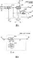
图1是本发明代码转换装置的第一实施例的构成示意图。在图1中,对于与图12相同或等同的要素用相同的参照标号标注。参照图1,具有输入端子10、代码分离电路1010、LP系数码转换电路1100、LSP-LPC转换电路1110、脉冲响应计算电路1120、ACB码转换电路1200、目标信号计算电路1700、FCB码生成电路1800、增益码生成电路1400、语音解码电路1500、第二激励信号计算电路1610、第二激励信号存储电路1620、代码复用电路1020、输出端子20。输入端子10、输出端子20、代码分离电路1010、代码复用电路1020除连接上有一部分不同之外,基本上与图12所示的要素相同。下面省略与上述相同或等同的要素的说明,而主要说明与图12所示的构成的不同点。Fig. 1 is a schematic diagram of the structure of the first embodiment of the code conversion device of the present invention. In FIG. 1 , the same reference numerals are assigned to the same or equivalent elements as those in FIG. 12 . Referring to Fig. 1, it has
此外,在方法A中,设定LP系数的编码每Furthermore, in Method A, the encoding of the LP coefficients is set every
Tfr(A)Tfr(A)
msec周期(帧)进行,ACB、FCB及增益等激励信号的构成要素的编码每msec cycle (frame), the encoding of the components of the excitation signal such as ACB, FCB and gain is performed every
msec周期(子帧)进行。The msec cycle (subframe) is performed.
另一方面,在方法B中,设定LP系数的编码每On the other hand, in method B, encoding of LP coefficients is set every
Tfr(B)Tfr(B)
msec周期(帧)进行,激励信号的构成要素的编码每The msec cycle (frame) is carried out, and the encoding of the constituent elements of the excitation signal is performed every
msec周期(子帧)进行。The msec cycle (subframe) is performed.
此外,分别将方法A的帧长、子帧数以及子帧长设为In addition, set the frame length, subframe number and subframe length of method A as
Lfr(A)、Lfr(A) 、
Nsfr(A)Nsfr(A)
及
分别将方法B的帧长、子帧数以及子帧长分别设为Set the frame length, number of subframes and subframe length of method B as
Lfr(B)、Lfr(B) 、
Nsfr(B)Nsfr(B)
及
在以下的说明中,为方便起见,设为In the following description, for convenience, set
此处,例如,若将取样频率设为8000Hz,将Here, for example, if the sampling frequency is set to 8000Hz, the
Tfr(A)Tfr(A)
及and
Tfr(B)Tfr(B)
设为10msec,set to 10msec,
则Lfr(A)Then Lfr(A)
及Lfr(B)and Lfr(B)
为160样本,for 160 samples,
Lsfr(A)Lsfr(A)
及and
Lsfr(B)Lsfr(B)
为80样本。for 80 samples.
LP系数码转换电路1100从代码分离电路1010输入第一LP系数码。此处,在《3GPP AMR Speech Codec》(文献3)或ITU-T建议G.729等很多标准方法中,由于用线谱对(Line Spectral Pair:LSP)表示LP系数,并对LSP进行编码及解码的时候很多,所以LP系数的编码及解码在LSP区域中进行。关于从LP系数向LSP的转换、以及从LSP向LP系数的转换的公知方法,例如可参见“文献3”的第5.2.3节及第6.2.4节的记载。LP系数码转换电路1100使用方法A中的LSP解码方法对所述第一LP系数码进行解码,从而得到第一LSP。The LP coefficient
接着,LP系数码转换电路1100使用方法B中的LSP量化方法及编码方法对所述第一LSP进行量化及编码,从而得到第二LSP和与其对应的代码(第二LP系数码)。然后,LP系数码转换电路1100将所述第二LP系数码作为可使用方法B中的LSP解码方法进行解码的代码输出给代码复用电路1020,并且将所述第一LSP和第二LSP输出给LSP-LPC转换电路1110。Next, the LP coefficient
图2是LP系数码转换电路1100的构成示意图。参照图2,LP系数码转换电路1100具有LSP解码电路110、第一LSP码本111、LSP系数编码电路130、第二LSP码本131。参照图2说明LP系数码转换电路1100的各构成要素。FIG. 2 is a schematic diagram of the structure of the LP coefficient
LSP解码电路110从LP系数码解码出所对应的LSP。LSP解码电路110具有存储了多组LSP的第一LSP码本111,并经由输入端子31输入从代码分离电路1010输出的第一LP系数码,从而从第一LSP码本111读取与第一LP系数码相对应的LSP并将读取的LSP作为第一LSP输出给LSP编码电路130,并经由输出端子33输出给LSP-LPC转换电路1110。此处,来自LP系数码的LSP的解码依据方法A中的LSP的解码方法,并使用方法A的LSP码本。The LSP decoding circuit 110 decodes the corresponding LSP from the LP coefficient code. The LSP decoding circuit 110 has a first LSP codebook 111 storing a plurality of sets of LSPs, and inputs the first LP coefficient code output from the
LSP编码电路130输入由LSP解码电路110输出的第一LSP,从存储有多组LSP的第二LSP码本131中依次分别读取第二LSP和与其对应的LP系数码,并选择与第一LSP之间的误差最小的第二LSP,从而将与其对应的LP系数码作为第二LP系数码经由输出端子32输出给代码复用电路1020,并且经由输出端子34将第二LSP输出给LSP-LPC转换电路1110。此处,第二LSP选择方法,即LSP量化及编码方法依据方法B中的LSP量化方法及编码方法,使用方法B的LSP码本。此处,关于LSP的量化及编码,参见例如“文献3”的第5.2.5节的记载。The LSP encoding circuit 130 inputs the first LSP output by the LSP decoding circuit 110, reads the second LSP and the LP coefficient codes corresponding to it in turn from the second LSP codebook 131 storing multiple groups of LSPs, and selects the codes corresponding to the first LSP The second LSP with the smallest error between LSPs, so that the corresponding LP coefficient code is output to the
至此,结束对图2中的LP系数码转换电路1100的说明,再次回到图1的说明。So far, the description of the LP coefficient
LSP-LPC转换电路1110输入由LP系数码转换电路1100输出的第一LSP和第二LSP,并将第一LSP转换为第一LP系数a1、i,将第二LSP转换为第二LP系数a2、i,从而将第一LP系数a1、I输出给目标信号计算电路1700、语音解码电路1500和脉冲响应计算电路1120,并将第二LP系数a2、i输出给目标信号计算电路1700和脉冲响应计算电路1120。此处,关于从LSP向LP系数的转换,参见“文献3”的第5.2.4节的记载。The LSP-LPC conversion circuit 1110 inputs the first LSP and the second LSP output by the LP coefficient
ACB码转换电路1200使用方法A中的代码和方法B中的代码之间的对应关系来对由代码分离电路1010输入的第一ACB码进行变换(読み替え),从而得到第二ACB码。并且,ACB码转换电路1200将第二ACB码作为可使用方法B中的ACB解码方法进行解码的代码输出给代码复用电路1020。此外,ACB码转换电路1200将与第二ACB码对应的ACB延迟作为第二ACB延迟输出给目标信号计算电路1700。The ACB code conversion circuit 1200 uses the correspondence between the codes in method A and the codes in method B to convert (replace) the first ACB code input by the
此处,参照图3说明代码的变换。例如,假设在方法A中的ACB码Here, conversion of codes will be described with reference to FIG. 3 . For example, assuming the ACB code in Method A
iT(A)iT(A)
为56时,与此对应的ACB延迟When it is 56, the ACB delay corresponding to this
T(A)T(A)
为76。若在方法B中,假设ACB码for 76. If in method B, assuming ACB code
iT(B)iT(B)
为53时,与此对应的ACB延迟When it is 53, the ACB delay corresponding to this
T(B)T(B)
为76,则为使ACB延迟的值相同(此时是76)而从方法A向方法B进行ACB码转换时,只要将方法A中的ACB码56与方法B中的ACB码53对应起来即可。至此,结束关于代码的变换的说明,再次返回到图1的说明。is 76, then in order to make the value of ACB delay the same (at this time, 76), when performing ACB code conversion from method A to method B, as long as the
语音解码电路1500输入由代码分离电路1010输出的第一ACB码、第一FCB码、第一增益码,并从LSP-LPC转换电路1110输入第一LP系数。接着,语音解码电路1500分别使用方法A中的ACB信号解码方法、FCB信号解码方法及增益解码方法,从第一ACB码、第一FCB码及第一增益码中分别解码出ACB延迟、FCB信号及增益,并将这些分别作为第一ACB延迟、第一FCB信号及第一增益。语音解码电路1500使用第一ACB延迟生成ACB信号,并将此作为第一ACB信号。并且,语音解码电路1500从第一ACB信号、第一FCB信号及第一增益和第一LP系数生成语音,并将语音输出给目标信号计算电路1700。The speech decoding circuit 1500 receives the first ACB code, the first FCB code, and the first gain code output from the
图4是语音解码电路1500的构成示意图。参照图4,语音解码电路1500具有激励信号信息解码电路1600、激励信号计算电路1540、激励信号存储电路1570和合成滤波器1580,其中所述激励信号信息解码电路1600具有ACB解码电路1510、FCB解码电路1520和增益解码电路1530。参照图4,说明语音解码电路1500的各构成要素。FIG. 4 is a schematic diagram of the structure of the speech decoding circuit 1500 . Referring to Fig. 4, speech decoding circuit 1500 has excitation signal information decoding circuit 1600, excitation
激励信号信息解码电路1600从与激励信号的信息对应的代码中解码出激励信号的信息。将由代码分离电路1010输出的第一ACB码、第一FCB码及第一增益码分别经由输入端子51、52及53输入,并分别从第一ACB码、第一FCB码及第一增益码中解码出ACB延迟、FCB信号及增益,并将这些分别作为第一ACB延迟、第一FCB信号及第一增益。此处,第一增益由ACB增益和FCB增益组成,分别将它们作为第一ACB增益和第一FCB增益。此外,激励信号信息解码电路1600输入由激励信号存储电路1570输出的过去的激励信号。激励信号信息解码电路1600使用过去的激励信号和第一ACB延迟生成ACB信号,并将此作为第一ACB信号。并且,激励信号信息解码电路1600将第一ACB信号、第一FCB信号、第一ACB增益及第一FCB增益输出给激励信号计算电路1540。The excitation signal information decoding circuit 1600 decodes the information of the excitation signal from the code corresponding to the information of the excitation signal. The first ACB code, the first FCB code and the first gain code output by the
下面,详细说明作为激励信号信息解码电路1600的构成要素的ACB解码电路1510、FCB解码电路1520和增益解码电路1530。Next,
ACB解码电路1510经由输入端子51输入由代码分离电路1010输出的第一ACB码,并输入由激励信号存储电路1570输出的过去的激励信号。接着,ACB解码电路1510与上述ACB码转换电路1200相同,使用图3所示的方法A中的ACB码和ACB延迟的对应关系,得到与第一ACB码对应的第一ACB延迟The
T(A)T(A)
。对于激励信号,从自当前子帧的始点. For the excitation signal, from the beginning of the current subframe
T(A)T(A)
采样过去的点截出与子帧长度相当的Sampling the past point to cut out the equivalent of the subframe length
Lsfr(A)Lsfr(A)
采样信号,从而生成第一ACB信号。此处,当The signal is sampled to generate a first ACB signal. here, when
T(A)T(A)
比Compare
Lsfr(A)Lsfr(A)
小时,截出hours, cut out
T(A)T(A)
采样量的矢量,并反复连接所述矢量,从而形成长度为vector of sampled quantities, and iteratively concatenates said vectors to form a length of
Lsft(A)Lsft(A)
的采样信号。然后,向激励信号计算电路1540输出第一ACB信号。此处,关于生成第一ACB信号的方法的详细说明,参见“文献3”的第6.1节及第5.6节的记载。the sampling signal. Then, the first ACB signal is output to the excitation
FCB解码电路1520经由输入端子52输入由代码分离电路1010输出的第一FCB码,并将与第一FCB码对应的第一FCB信号输出给激励信号计算电路1540。FCB信号表现为由脉冲位置和脉冲极性规定的多脉冲信号,因此第一FCB码由与脉冲位置对应的代码(脉冲位置代码)和与脉冲极性对应的代码(脉冲极性代码)组成。此处,关于生成表现为多脉冲信号的FCB信号的方法的详细说明,参见“文献3”的第6.1节及第5.7节的记载。The
增益解码电路1530经由输入端子53输入由代码分离电路1010输出的第一增益码。增益解码电路1530内置有存储了多个增益的表格,并从表格中读取与第一增益码对应的增益。然后,增益解码电路1530向激励信号计算电路1540输出在所读取的增益之中与ACB增益对应的第一ACB增益、与FCB增益对应的第一FCB增益。此处,在将第一ACB增益和第一FCB增益一起编码的情况下,在表格中存储多个由第一ACB增益和第一FCB增益组成的二维矢量。此外,在将第一ACB增益和第一FCB增益分别编码的情况下,内置两个表格,并在一个表格中存储多个第一ACB增益,在另一个表格中存储多个第一FCB增益。The
激励信号计算电路1540输入由ACB解码电路1510输出的第一ACB信号、由FCB解码电路1520输出的第一FCB信号以及由增益解码电路1530输出的第一ACB增益和第一FCB增益。激励信号计算电路1540将在第一ACB信号上乘上第一ACB增益所得的信号和在第一FCB信号上乘上第一FCB增益所得的信号相加起来,从而得到第一激励信号。然后,激励信号计算电路1540向合成滤波器1580和激励信号存储电路1570输出第一激励信号。The excitation
激励信号存储电路1570输入由激励信号计算电路1540输出的第一激励信号,并将其存储保持。并且,激励信号存储电路1570将在过去输入并存储保持的过去的第一激励信号输出给ACB解码电路1510。The excitation
合成滤波器1580输入由激励信号计算电路1540输出的第一激励信号,并经由输入端子61输入由LSP-LPC转换电路1110输出的第一LP系数。然后,合成滤波器1580通过使用第一激励信号驱动具有第一LP系数的线性预测滤波器来生成语音。并经由输出端子63将语音信号输出给目标信号计算电路1700。The
至此,结束对图4中的语音解码电路1500的说明,再次返回到图1的说明。So far, the description of the speech decoding circuit 1500 in FIG. 4 is finished, and the description of FIG. 1 is returned again.
目标信号计算电路1700从LSP-LPC转换电路1110输入第一LSP和第二LSP,从ACB码转换电路1200输入与第二ACB码对应的第二ACB延迟,从语音解码电路1500输入解码语音,从脉冲响应计算电路1120输入脉冲响应信号,并输入存储保持在第二激励信号存储电路1620中的过去的第二激励信号。目标信号计算电路1700从解码语音和第一LP系数及第二LP系数算出第一目标信号。接着,目标信号计算电路1700从过去的第二激励信号、脉冲响应信号、第一目标信号和第二ACB延迟求出第二ACB信号及最佳ACB增益。然后,目标信号计算电路1700向增益码生成电路1400输出第一目标信号和最佳ACB增益,向增益码生成电路1400和第二激励信号计算电路1610输出第二ACB信号。The target signal calculation circuit 1700 inputs the first LSP and the second LSP from the LSP-LPC conversion circuit 1110, inputs the second ACB delay corresponding to the second ACB code from the ACB code conversion circuit 1200, inputs the decoded speech from the speech decoding circuit 1500, The impulse response calculation circuit 1120 inputs the impulse response signal and inputs the past second excitation signal stored and held in the second excitation signal storage circuit 1620 . The target signal calculation circuit 1700 calculates the first target signal from the decoded speech and the first LP coefficient and the second LP coefficient. Next, the target signal calculation circuit 1700 calculates the second ACB signal and the optimum ACB gain from the past second excitation signal, impulse response signal, first target signal, and second ACB delay. Then, the target signal calculation circuit 1700 outputs the first target signal and the optimal ACB gain to the gain code generation circuit 1400 , and outputs the second ACB signal to the gain code generation circuit 1400 and the second excitation signal calculation circuit 1610 .
图5是目标信号计算电路1700的构成示意图。参照图5,目标信号计算电路1700具有加权信号计算电路1710、ACB信号生成电路1720和最佳ACB增益计算电路1730。参照图5说明目标信号计算电路1700的各构成要素。FIG. 5 is a schematic diagram of the structure of the target signal calculation circuit 1700 . Referring to FIG. 5 , the target signal calculation circuit 1700 has a weighted
加权信号计算电路1710经由输入端子57输入由语音解码电路1500的合成滤波器1580输出的解码语音s(n),并分别经由输入端子36和输入端子35输入由LSP-LPC转换电路1110输出的第一LP系数a1、i和第二LP系数a2、i。加权信号计算电路1710首先使用第一LP系数构成听感加权滤波器W(z)。The weighted
然后,加权信号计算电路1710使用解码语音驱动听感加权滤波器,从而生成听感加权语音信号。接着,加权信号计算电路1710使用第一LP系数和第二LP系数构成听感加权合成滤波器W(z)/A2(z)。Then, the weighted
然后,加权信号计算电路1710将从听感加权语音信号减去听感加权合成滤波器的零输入响应而得的第一目标信号X(n)输出给ACB信号生成电路1720和最佳ACB增益计算电路1730,并且经由输出端子78输出给第二目标信号计算电路1430。Then, the weighted
ACB信号生成电路1720输入由加权信号计算电路1710输出的第一目标信号,并且经由输入端子37输入由ACB码转换电路1200输出的第二ACB延迟T(B)lag,经由输入端子74输入由脉冲响应计算电路1120输出的脉冲响应信号h(n),经由输入端子75输入由第二激励信号存储电路1620输出的过去的第二激励信号u(n)。The ACB
ACB信号生成电路1720根据以延迟k从过去的第二激励信号中截出的信号和脉冲信号之间的卷积(畳み込み)来计算滤波器处理后的延迟k的过去的激励信号The ACB
此处,延迟k是第二ACB延迟。以延迟k从过去的第二激励信号中截出的信号是第二ACB信号v(n)。Here, delay k is the second ACB delay. The signal truncated with delay k from the past second excitation signal is the second ACB signal v(n).
然后,ACB信号生成电路1720经由输出端子76将第二ACB信号输出给第二目标信号计算电路1430和第二激励信号计算电路1610,并将滤波器处理后的延迟k的过去的激励信号yk(n)输出给最佳ACB增益计算电路1730。Then, the ACB
最佳ACB增益计算电路1730输入由加权信号计算电路1710输出的第一目标信号x(n),并输入由ACB信号生成电路1720输出的滤波器处理后的延迟k的过去的激励信号yk(n)。The optimum ACB
接着,ACB增益计算电路1730根据下式从第一目标信号x(n)和滤波器处理后的延迟k的过去的激励信号yk(n)算出最佳ACB增益gp。最佳ACB增益gp是使第一目标信号x(n)和滤波器处理后的延迟k的过去的激励信号yk(n)之间的距离最小的增益。Next, the ACB
然后,ACB增益计算电路1730经由输出端子77向ACB增益编码电路1410输出最佳ACB增益gp。Then, the ACB
此外,关于计算第二ACB信号的方法及计算最佳ACB增益的方法的详细说明,参见“文献3”的第6.1节及第5.6节的记载。至此,结束对图5的目标信号计算电路1700的说明,再次返回到图1的说明。In addition, for a detailed description of the method of calculating the second ACB signal and the method of calculating the optimum ACB gain, refer to the descriptions in Section 6.1 and Section 5.6 of "Document 3". So far, the description of the target signal calculation circuit 1700 in FIG. 5 ends, and the description returns to FIG. 1 again.
脉冲响应计算电路1120输入由LSP-LPC转换电路1110输出的第一LP系数和第二LP系数,并且使用第一LP系数和第二LP系数构成听感加权合成滤波器。The impulse response calculation circuit 1120 inputs the first LP coefficient and the second LP coefficient output from the LSP-LPC conversion circuit 1110, and uses the first LP coefficient and the second LP coefficient to constitute a sense of hearing weighted synthesis filter.
然后,脉冲响应计算电路1120向目标信号计算电路1700和增益码生成电路1400输出听感加权合成滤波器的脉冲响应信号。此处,听感加权合成滤波器的传递函数用下式表示。Then, the impulse response calculation circuit 1120 outputs the impulse response signal of the sense of hearing weighted synthesis filter to the target signal calculation circuit 1700 and the gain code generation circuit 1400 . Here, the transfer function of the sense of hearing weighted synthesis filter is represented by the following equation.
其中,in,
是具有第二LP系数is the coefficient with the second LP
a2,i,i=1,…,Pa2,i ,i=1,...,P
的线性预测滤波器的传递函数。The transfer function of the linear predictive filter.
是具有第一LP系数is the coefficient with the first LP
a1,i,i=1,…,Pa1,i ,i=1,...,P
的听感加权滤波器的传递函数。The transfer function of the auditory weighting filter.
此处,P是线性预测次数(例如为10),r1和r2是控制加权的系数(例如为0.94和0.6)。Here, P is the number of linear predictions (for example, 10), and r1 and r2 are coefficients for controlling weighting (for example, 0.94 and 0.6).
FCB码生成电路1800输入由代码分离电路1010输出的第一FCB码,并将第一FCB码转换成可使用方法B进行解码的代码。FCB码生成电路1800将转换后的FCB码作为第二FCB码输出给代码复用电路1020,将与第二FCB码对应的第二FCB信号输出给增益码生成电路1400和第二激励信号计算电路1610。此处,FCB信号由多个脉冲组成,表现为由脉冲的位置(脉冲位置)和极性(脉冲极性)规定的多脉冲信号。FCB码由与脉冲位置对应的代码(脉冲位置代码)和与脉冲极性对应的代码(脉冲极性代码)组成。关于FCB信号的使用多脉冲信号的表现方法,参见“文献3”的第5.7节的记载。The FCB code generation circuit 1800 inputs the first FCB code output by the
图6是图1的FCB码生成电路1800的构成示意图。参照图6,FCB码生成电路1800具有FCB码转换电路1300和FCB信号生成电路1820。参照图6,说明FCB码生成电路1800的各构成要素。FIG. 6 is a schematic diagram of the structure of the FCB code generation circuit 1800 in FIG. 1 . Referring to FIG. 6 , the FCB code generation circuit 1800 has an FCB
FCB码转换电路1300使用方法A中的代码和方法B中的代码之间的对应关系对从代码分离电路1010经由输入端子85输入的第一FCB码i(A)P进行变换,从而得到第二FCB码i(B)P。然后,FCB码转换电路1300将其作为可使用方法B中的FCB解码方法进行解码的代码经由输出端子55输出给代码复用电路1020,并将与第二FCB码对应的脉冲位置The FCB
Pi(A)Pi(A)
及脉冲极性and pulse polarity
Si(A)Si(A)
输出给FCB信号生成电路1820。Output to the FCB
参照图7说明脉冲位置代码的变换。The conversion of the pulse position code will be described with reference to FIG. 7 .
例如,当方法A中的脉冲位置代码For example, when the pulse position code in Method A
iP(A)iP(A)
是6时,与其对应的脉冲位置When it is 6, the corresponding pulse position
P0(A)P0(A)
是30。若在方法B中,假设当脉冲位置代码It's 30. If in method B, assume that when the pulse position code
iP(B)iP(B)
为1时,与其对应的脉冲位置When it is 1, the corresponding pulse position
P0(B)P0(B)
为30,则为使脉冲位置的值相同(此时是30)而从方法A向方法B进行脉冲位置代码的转换时,只要将方法A中的脉冲位置代码6与方法B中的脉冲位置代码1对应起来即可。If it is 30, then to make the value of the pulse position the same (30 at this time), when converting the pulse position code from method A to method B, as long as the pulse position code 6 in method A and the pulse position code in
关于脉冲极性代码,只要对代码进行变换,使得对应于变换之前的代码的极性(正或负)和对应于变换之后的代码的极性相同即可。Regarding the pulse polarity code, it is only necessary to transform the code so that the polarity (positive or negative) corresponding to the code before the transformation is the same as the polarity corresponding to the code after the transformation.
至此,结束关于脉冲位置代码及脉冲极性代码的变换的说明,再次返回到图6的说明。So far, the description about the conversion of the pulse position code and the pulse polarity code ends, and the description returns to FIG. 6 again.
FCB信号生成电路1820输入由FCB码转换电路1300输出的脉冲位置及脉冲极性。FCB信号生成电路1820将由脉冲位置及脉冲极性规定的FCB信号作为第二FCB信号c(n),并经由输出端子86将其输出给最佳FCB增益计算电路1440和第二激励信号计算电路1610。The FCB
至此,结束对图6的FCB码生成电路1800的说明,再次返回到图1的说明。So far, the description of the FCB code generation circuit 1800 in FIG. 6 ends, and the description returns to FIG. 1 again.
增益码生成电路1400输入由目标信号计算电路1700输出的第一目标信号、第二ACB信号和最佳ACB增益,输入由FCB码生成电路1800输出的第二FCB信号,输入由脉冲响应计算电路1120输出的脉冲响应信号,输入由LP系数码转换电路1100输出的第一LSP。The gain code generation circuit 1400 inputs the first target signal output by the target signal calculation circuit 1700, the second ACB signal and the optimum ACB gain, inputs the second FCB signal output by the FCB code generation circuit 1800, and inputs the second FCB signal output by the impulse response calculation circuit 1120 The output impulse response signal is input to the first LSP output by the LP coefficient
增益码生成电路1400首先从第一目标信号、第二ACB信号、最佳ACB增益和脉冲响应信号算出第二目标信号,从第二目标信号、第二FCB信号和脉冲响应信号算出最佳FCB增益,从最佳FCB增益算出修正FCB增益,并从第一LSP确定语音判定值。The gain code generating circuit 1400 first calculates the second target signal from the first target signal, the second ACB signal, the best ACB gain and the impulse response signal, and calculates the best FCB gain from the second target signal, the second FCB signal and the impulse response signal , calculate the modified FCB gain from the optimal FCB gain, and determine the speech decision value from the first LSP.
接着,增益码生成电路1400从依次从ACB增益码本读取的ACB增益和最佳ACB增益算出第一平方误差,并从ACB增益和修正ACB增益算出第二平方误差。Next, the gain code generation circuit 1400 calculates a first square error from the ACB gain read sequentially from the ACB gain codebook and the optimum ACB gain, and calculates a second square error from the ACB gain and the corrected ACB gain.
并且,增益码生成电路1400选择使评价函数最小的ACB增益以及所对应的ACB增益码,其中所述评价函数是从自语音判定值算出的权重系数、第一平方误差和第二平方误差算出的。And, the gain code generating circuit 1400 selects the ACB gain and the corresponding ACB gain code that minimize the evaluation function calculated from the weight coefficient calculated from the voice decision value, the first square error and the second square error .
此外,增益码生成电路1400从依次从FCB增益码本读取的FCB增益和最佳FCB增益算出第三平方误差,并且由FCB增益和修正FCB增益算出第四平方误差。In addition, the gain code generating circuit 1400 calculates a third square error from the FCB gain read sequentially from the FCB gain codebook and the optimum FCB gain, and calculates a fourth square error from the FCB gain and the corrected FCB gain.
并且,增益码生成电路1400选择使评价函数最小的FCB增益以及所对应的FCB增益码,其中所述评价函数是从自语音判定值算出的权重系数、第三平方误差和第四平方误差算出的。And, the gain code generating circuit 1400 selects the FCB gain and the corresponding FCB gain code that minimize the evaluation function calculated from the weight coefficient calculated from the voice decision value, the third square error and the fourth square error .
最后,增益码生成电路1400经由输出端子56向代码复用电路1020输出由所选择的ACB增益码和FCB增益码组成的第二增益码,作为可使用方法B中的增益解码方法进行解码的代码。Finally, the gain code generation circuit 1400 outputs the second gain code composed of the selected ACB gain code and FCB gain code to the
图8是增益码生成电路1400的构成示意图。参照图8,增益码生成电路1400具有ACB增益编码电路1410、ACB增益码本1411、FCB增益编码电路1420、FCB增益码本1421、第二目标信号计算电路1430、最佳FCB增益计算电路1440、最佳FCB增益修正电路1450、语音/非语音识别电路1460。参照图8,详细说明增益码生成电路1400的各构成要素。FIG. 8 is a schematic diagram of the structure of the gain code generating circuit 1400 . Referring to Fig. 8, the gain code generating circuit 1400 has an ACB gain encoding circuit 1410, an ACB gain codebook 1411, an FCB gain encoding circuit 1420, an FCB gain codebook 1421, a second target signal calculation circuit 1430, an optimum FCB gain calculation circuit 1440, Optimum FCB gain correction circuit 1450, speech/non-speech recognition circuit 1460. Referring to FIG. 8, each component of the gain code generation circuit 1400 will be described in detail.
第二目标信号计算电路1430经由输入端子92输入由ACB信号生成电路1720输出的第二ACB信号v(n),经由输入端子93输入由加权信号计算电路1710输出的第一目标信号x(n),经由输入端子94输入由脉冲响应计算电路1120输出的脉冲响应信号h(n),并输入由ACB增益编码电路1410输出的第二ACB增益。The second target signal calculation circuit 1430 inputs the second ACB signal v(n) output from the ACB
第二目标信号计算电路1430根据第二ACB信号和脉冲响应信号的卷积来计算滤波器处理后的第二ACB信号The second target signal calculation circuit 1430 calculates the filter-processed second ACB signal according to the convolution of the second ACB signal and the impulse response signal
,并从第一目标信号x(n)中减去y(n)乘以第二ACB增益, and subtract y(n) times the second ACB gain from the first target signal x(n)
所得的信号,从而得到第二目标信号x2(n)。The obtained signal, so as to obtain the second target signal x2 (n).
y(n)=v(n)*h(n)y(n)=v(n)*h(n)
然后,第二目标信号计算电路1430向最佳FCB增益计算电路1440输出第二目标信号x2(n)。Then, the second target signal calculation circuit 1430 outputs the second target signal x2 (n) to the optimal FCB gain calculation circuit 1440 .
最佳FCB增益计算电路1440经由输入端子91输入由FCB信号生成电路1820输出的第二FCB信号c(n),经由输入端子94输入由脉冲响应计算电路1120输出的脉冲响应信号h(n),输入由第二目标信号计算电路1430输出的第二目标信号x2(n),从而根据第二FCB信号和脉冲响应信号的卷积来计算滤波器处理后的第二FCB信号The optimum FCB gain calculation circuit 1440 inputs the second FCB signal c(n) output by the FCB
,并根据下式从第二目标信号x2(n)和滤波器处理后的第二FCB信号z(n)算出最佳FCB增益gc。最佳FCB增益gc是使第二目标信号x2(n)和滤波器处理后的第二FCB信号z(n)之间的距离最小的增益。, and calculate the optimal FCB gain gc from the second target signal x2 (n) and the filtered second FCB signal z(n) according to the following formula. The optimal FCB gain gc is the gain that minimizes the distance between the second target signal x2 (n) and the filtered second FCB signal z(n).
然后,最佳FCB增益计算电路1440将最佳FCB增益输出给最佳FCB增益修正电路1450和FCB增益编码电路1420。Then, the optimal FCB gain calculation circuit 1440 outputs the optimal FCB gain to the optimal FCB gain modification circuit 1450 and the FCB gain encoding circuit 1420 .
语音/非语音识别电路1460经由输入端子98输入由LSP解码电路110输出的第一LSP。并从第一LSP和其长时间平均算出LSP的变动量,从LSP变动量确定语音判定值。The speech/non-speech recognition circuit 1460 inputs the first LSP output from the LSP decoding circuit 110 via the input terminal 98 . And calculate the variation amount of LSP from the first LSP and its long-term average, and determine the voice judgment value from the variation amount of LSP.
求LSP变动量的步骤如下所述。在第n帧中按照下式计算LSP的长时间平均The procedure for calculating the LSP variation is as follows. In the nth frame, the long-term average of LSP is calculated according to the following formula
此处,NP是线性预测次数,β例如是0.9。Here,NP is the number of linear predictions, and β is, for example, 0.9.
第n帧的LSP变动量dq(n)用下式定义。The LSP fluctuation amount dq(n) of the nth frame is defined by the following equation.
此处,here,
Dq,j(m)(n)Dq, j(m) (n)
可以定义为can be defined as

和and
之间的误差,例如可定义为The error between, for example, can be defined as
或or
等,此处使用后者。可使变动量dq(n)大的区间对应语音区间,使变动量dq(n)小的区间对应非语音区间。通过对变动量dq(n)的阈值处理来确定语音判定值etc., the latter is used here. A section with a large variation dq(n) can be associated with a speech section, and a section with a small variation dq(n) can be associated with a non-speech section. Determine the speech decision value by thresholding the variation dq(n)
Vs。Vs .
if(dq(n)≥Cvs)then Vs=1if(dq (n)≥Cvs )then Vs =1
else Vs=0else Vs =0
(Vs=1 dq(n)大于或等于CVS的情况(Vs =1 dq(n) is greater than or equal to the case of CVS
Vs=0 dq(n)小于CVS的情况)Vs =0 dq(n) is less than CVS)
此处,Cvs是某一常数(例如为2.2),并且Vs=1对应语音区间,Vs=0对应非语音区间。将语音判定值输出给最佳ACB增益修正电路1480、ACB增益编码电路1410、最佳FCB增益修正电路1450和FCB增益编码电路1420。Here, Cvs is a certain constant (for example, 2.2), and Vs =1 corresponds to a speech interval, and Vs =0 corresponds to a non-speech interval. The speech determination value is output to the optimum ACB gain correction circuit 1480 , the ACB gain encoding circuit 1410 , the optimum FCB gain correction circuit 1450 and the FCB gain encoding circuit 1420 .
最佳ACB增益修正电路1480经由输入端子97输入由ACB信号生成电路1720输出的最佳ACB增益,并且输入由语音/非语音识别电路1460输出的语音判定值。在最佳ACB增益修正电路1480中,当语音判定值Vs是0(非语音区间)时,将最佳ACB增益的长时间平均作为修正ACB增益。在非语音区间中,根据下式计算最佳ACB增益的长时间平均。The optimum ACB gain correction circuit 1480 inputs the optimum ACB gain output from the ACB
此处,here,
gp(n)gp (n)
是第n子帧中的最佳ACB增益,is the best ACB gain in the nth subframe,

是第n子帧中的最佳ACB增益的长时间平均,并且α例如是0.9。此外,平均值、中值、最频值等都可适用于长时间平均。is the long-term average of the best ACB gain in the nth subframe, and α is, for example, 0.9. In addition, average, median, mode, etc. can be applied to long-term averaging.
另一方面,在最佳ACB增益修正电路1480中,当语音判定值Vs是1(语音区间)时,将最佳ACB增益本身作为修正ACB增益。On the other hand, in the optimum ACB gain correction circuit 1480, when the speech determination valueVs is 1 (speech interval), the optimum ACB gain itself is used as the correction ACB gain.
最佳ACB增益修正电路1480将修正ACB增益输出给ACB增益编码电路1410。The optimum ACB gain modification circuit 1480 outputs the modified ACB gain to the ACB gain encoding circuit 1410 .
ACB增益编码电路1410经由输入端子97输入由ACB信号生成电路1720输出的最佳ACB增益gp,输入由最佳ACB增益修正电路1480输出的修正ACB增益,输入由语音/非语音识别电路1460输出的语音判定值。The ACB gain encoding circuit 1410 inputs the optimum ACB gain gp output by the ACB
ACB增益编码电路1410从依次从ACB增益码本1411读取的ACB增益和来自输入端子97的最佳ACB增益算出第一平方误差,从ACB增益和修正ACB增益算出第二平方误差,从根据语音判定值算出的权重系数、第一平方误差和第二平方误差算出由下式定义的评价函数。The ACB gain encoding circuit 1410 calculates the first square error from the ACB gain read sequentially from the ACB gain codebook 1411 and the optimum ACB gain from the input terminal 97, calculates the second square error from the ACB gain and the modified ACB gain, and calculates the second square error from the ACB gain and the corrected ACB gain. The weight coefficient calculated from the determination value, the first square error and the second square error calculate an evaluation function defined by the following equation.
此处,here,
gpgp
是最佳ACB增益,is the optimal ACB gain,
是修正ACB增益,is the modified ACB gain,
是从ACB增益码本依次读取的ACB增益,μ是权重系数。例如,当语音判定值Vs是1(语音区间)时,权重系数μ是1.0,当Vs是0(非语音区间)时,μ是0.2。is the ACB gain sequentially read from the ACB gain codebook, and μ is the weight coefficient. For example, when the speech determination value Vs is 1 (speech interval), the weight coefficient μ is 1.0, and when Vs is 0 (non-speech interval), μ is 0.2.
并且,ACB增益编码电路1410选择使评价函数最小的ACB增益,并将所选择的ACB增益作为第二ACB增益输出给第二目标信号计算电路1430,同时经由输出端子95输出给第二激励信号计算电路1610,将与第二ACB增益对应的代码作为ACB增益码输出给增益码复用电路1470。Also, the ACB gain encoding circuit 1410 selects the ACB gain that minimizes the evaluation function, and outputs the selected ACB gain as the second ACB gain to the second target signal calculation circuit 1430, and at the same time outputs it to the second excitation signal calculation circuit 1430 via the output terminal 95. The circuit 1610 outputs the code corresponding to the second ACB gain as an ACB gain code to the gain code multiplexing circuit 1470 .
最佳FCB增益修正电路1450输入由最佳FCB增益计算电路1440输出的最佳FCB增益,并且输入由语音/非语音识别电路1460输出的语音判定值。The optimum FCB gain correction circuit 1450 inputs the optimum FCB gain output from the optimum FCB gain calculation circuit 1440 , and inputs the speech determination value output from the speech/non-speech recognition circuit 1460 .
在最佳FCB增益修正电路1450中,当语音判定值Vs是0(非语音区间)时,将最佳FCB增益的长时间平均作为修正FCB增益。在非语音区间中,根据下式计算最佳FCB增益的长时间平均。In the optimum FCB gain correction circuit 1450, when the speech determination value Vs is 0 (non-speech interval), the long-term average of the optimum FCB gain is used as the corrected FCB gain. In the non-speech interval, the long-term average of the optimum FCB gain is calculated according to the following formula.
此处,here,
gc(n)gc (n)
是第n子帧中的最佳FCB增益,is the best FCB gain in the nth subframe,

是第n子帧中的最佳FCB增益的长时间平均,并且α例如是0.9。此外,平均值、中值、最频值等都可适用于长时间平均。is the long-term average of the best FCB gain in the nth subframe, and α is, for example, 0.9. In addition, average, median, mode, etc. can be applied to long-term averaging.
另一方面,在最佳FCB增益修正电路1450中,当语音判定值Vs为1(语音区间)时,将最佳FCB增益本身作为修正FCB增益。On the other hand, in the optimum FCB gain correction circuit 1450, when the speech determination valueVs is 1 (speech interval), the optimum FCB gain itself is used as the corrected FCB gain.
最佳FCB增益修正电路1450将修正FCB增益输出给FCB增益编码电路1420。The optimum FCB gain modification circuit 1450 outputs the modified FCB gain to the FCB gain encoding circuit 1420 .
FCB增益编码电路1420输入由最佳FCB增益计算电路1440输出的最佳FCB增益,输入由最佳FCB增益修正电路1450输出的修正FCB增益,输入由语音/非语音识别电路1460输出的语音判定值。FCB增益编码电路1420从依次从FCB增益码本1421读取的FCB增益和最佳FCB增益算出第一平方误差,从FCB增益和修正FCB增益算出第二平方误差,从根据语音判定值算出的权重系数、第一平方误差和第二平方误差算出由下式定义的评价函数。The FCB gain encoding circuit 1420 inputs the optimum FCB gain output by the optimum FCB gain calculation circuit 1440, inputs the corrected FCB gain output by the optimum FCB gain correction circuit 1450, and inputs the speech judgment value output by the speech/non-speech recognition circuit 1460 . The FCB gain coding circuit 1420 calculates the first square error from the FCB gain read sequentially from the FCB gain codebook 1421 and the optimum FCB gain, calculates the second square error from the FCB gain and the corrected FCB gain, and calculates the second square error from the weight calculated from the speech determination value. The coefficient, the first square error, and the second square error calculate an evaluation function defined by the following equation.
此处,here,
gcgc
是最佳FCB增益,is the optimal FCB gain,
是修正FCB增益,is the modified FCB gain,

是从FCB增益码本依次读取的FCB增益,μ是权重系数。例如,当语音判定值Vs是1(语音区间)时,权重系数μ是1.0,当Vs是0(非语音区间)时,μ是0.2。is the FCB gain sequentially read from the FCB gain codebook, and μ is the weight coefficient. For example, when the speech determination value Vs is 1 (speech interval), the weight coefficient μ is 1.0, and when Vs is 0 (non-speech interval), μ is 0.2.
然后,FCB增益编码电路1420选择使评价函数最小的FCB增益,并将所选择的FCB增益作为第二FCB增益经由输出端子96输出给第二激励信号计算电路1610,将与第二FCB增益对应的代码作为FCB增益码输出给增益码复用电路1470。Then, the FCB gain encoding circuit 1420 selects the FCB gain that minimizes the evaluation function, and outputs the selected FCB gain as the second FCB gain to the second excitation signal calculation circuit 1610 via the output terminal 96, and the FCB gain corresponding to the second FCB gain The codes are output to gain code multiplexing circuit 1470 as FCB gain codes.
增益码复用电路1470输入由ACB增益编码电路1410输出的ACB增益码,输入由FCB增益编码电路1420输出的FCB增益码,并将ACB增益码和FCB增益码进行复用而得的第二增益码作为可使用方法B中的增益解码方法进行解码的代码输出给代码复用电路1020。The gain code multiplexing circuit 1470 inputs the ACB gain code output by the ACB gain coding circuit 1410, inputs the FCB gain code output by the FCB gain coding circuit 1420, and multiplexes the ACB gain code and the FCB gain code to obtain the second gain The code is output to the
至此,结束对图8的增益码生成电路1400的说明,再次返回到图1的说明。So far, the description of the gain code generation circuit 1400 in FIG. 8 is finished, and the description of FIG. 1 is returned again.
第二激励信号计算电路1610输入由目标信号计算电路1700输出的第二ACB信号,输入由FCB码生成电路1800输出的第二FCB信号,输入由增益码生成电路1400输出的第二ACB增益和第二FCB增益。第二激励信号计算电路1610将第二ACB信号乘上第二ACB增益所得到的信号和第二FCB信号乘上第二FCB增益所得到的信号相加,从而得到第二激励信号。然后将第二激励信号输出给第二激励信号存储电路1620。The second excitation signal calculation circuit 1610 inputs the second ACB signal output by the target signal calculation circuit 1700, inputs the second FCB signal output by the FCB code generation circuit 1800, and inputs the second ACB gain output by the gain code generation circuit 1400 and the second ACB gain output by the gain code generation circuit 1400. Two FCB gains. The second excitation signal calculation circuit 1610 adds the signal obtained by multiplying the second ACB signal by the second ACB gain and the signal obtained by multiplying the second FCB signal by the second FCB gain, so as to obtain the second excitation signal. Then the second excitation signal is output to the second excitation signal storage circuit 1620 .
第二激励信号存储电路1620输入由第二激励信号计算电路1610输出的第二激励信号,并将其存储保持。并且,将在过去输入并存储保持的第二激励信号输出给目标信号计算电路1700。至此,结束对本发明第一实施例的说明。The second excitation signal storage circuit 1620 inputs the second excitation signal output by the second excitation signal calculation circuit 1610, and stores and holds it. And, the second excitation signal input and stored in the past is output to the target signal calculation circuit 1700 . So far, the description of the first embodiment of the present invention is ended.
第二实施例second embodiment
下面说明本发明的第二实施例。图9是本发明代码转换装置的第二实施例的构成示意图。在图9中,用LP系数码转换电路1100和增益码转换电路2400分别替换图12中的LP系数码转换电路100和增益码转换电路400,并且在LP系数码转换电路1100和增益码转换电路2400之间添加连接线。以下省略对与图12所示的要素相同或等同的要素的说明,仅说明不同点。Next, a second embodiment of the present invention will be described. Fig. 9 is a schematic structural diagram of the second embodiment of the code conversion device of the present invention. In FIG. 9, the LP coefficient
LP系数码转换电路1100与使用图1说明的第一实施例中的相同。但是与其他电路之间的连线方法不同,将第一LSP输出给增益码转换电路400。The LP coefficient
增益码转换电路2400输入由代码分离电路1010输出的第一增益码,并输入由LP系数码转换电路1100输出的第一LSP。The gain
增益码转换电路2400首先从第一增益(第一ACB增益及第一FCB增益)算出修正ACB增益及修正FCB增益,从第一LSP确定语音判定值,其中所述第一增益是将第一增益码使用方法A中的增益解码方法解码后所得到的。The gain
接着,增益码转换电路2400从依次从ACB增益码本读取的ACB增益和第一ACB增益算出第一平方误差,并从ACB增益和修正ACB增益算出第二平方误差。Next, the gain
然后,增益码转换电路2400选择使评价函数最小的ACB增益及所对应的ACB增益码,所述评价函数是从根据语音判定值算出的权重系数、第一平方误差和第二平方误差算出的。Then, the gain
并且,增益码转换电路2400从依次从FCB增益码本读取的F CB增益和第一FCB增益算出第三平方误差,从FCB增益和修正FCB增益算出第四平方误差。然后,增益码转换电路2400选择使评价函数最小的FCB增益及所对应的FCB增益码,所述评价函数是从根据语音判定值算出的权重系数、第三平方误差和第四平方误差算出的。In addition, the gain
最后,增益码转换电路2400将由所选择的ACB增益码和FCB增益码组成的第二增益码作为可使用方法B中的增益解码方法进行解码的代码输出给代码复用电路1020。Finally, the gain
图10是图9的增益码转换电路2400的构成示意图。参照图10,增益码转换电路2400具有语音/非语音识别电路1460、增益码分离电路2490、ACB增益解码电路2470、ACB增益码本2471、ACB增益修正电路2440、ACB增益编码电路2410、ACB增益码本1411、FCB增益解码电路2480、FCB增益码本2481、FCB增益修正电路2450、FCB增益编码电路2420、FCB增益码本1421以及增益码复用电路1470。参照图10,说明本实施例的增益码转换电路2400的各构成要素。此外,在图10中,语音/非语音识别电路1460及增益码复用电路1470与图8所示的要素基本相同,因此下面省略对它们的说明。FIG. 10 is a schematic diagram of the structure of the gain
增益码分离电路2490经由输入端子45输入由代码分离电路1010输出的第一增益码,并从第一增益码分离出与ACB增益及FCB增益对应的代码,即第一ACB增益码即第一FCB增益码,从而向ACB增益解码电路2470输出第一ACB增益码,向FCB增益解码电路2480输出第一FCB增益码。The gain code separation circuit 2490 inputs the first gain code output by the
ACB增益解码电路2470具有存储了多组ACB增益的ACB增益码本2471,并输入由增益码分离电路2490输出的第一ACB增益码,从而从ACB增益码本2471读取与第一ACB增益码对应的ACB增益,并将读取的ACB增益作为第一ACB增益输出给ACB增益修正电路2440,同时输出给ACB增益编码电路2410。此处,从ACB增益码的ACB增益的解码根据方法A中的ACB增益的解码方法,并使用方法A的ACB增益码本进行。The ACB gain decoding circuit 2470 has an ACB gain codebook 2471 storing multiple groups of ACB gains, and inputs the first ACB gain code output by the gain code separation circuit 2490, thereby reading the first ACB gain code from the ACB gain codebook 2471. corresponding ACB gain, and output the read ACB gain as the first ACB gain to the ACB gain correction circuit 2440 , and output it to the ACB gain encoding circuit 2410 at the same time. Here, the decoding of the ACB gain from the ACB gain code is performed using the ACB gain codebook of method A according to the ACB gain decoding method in method A.
FCB增益解码电路2480具有存储了多组FCB增益的FCB增益码本2481,并输入由增益码分离电路2490输出的第一FCB增益码,从而从FCB增益码本2481读取与第一FCB增益码对应的FCB增益,并将读取的FCB增益作为第一FCB增益输出给FCB增益修正电路2450,同时输出给FCB增益编码电路2420。此处,从FCB增益码的FCB增益的解码根据方法A中的FCB增益的解码方法,并使用方法A的FCB增益码本进行。The FCB gain decoding circuit 2480 has an FCB gain codebook 2481 storing multiple sets of FCB gains, and inputs the first FCB gain code output by the gain code separation circuit 2490, thereby reading the first FCB gain code from the FCB gain codebook 2481. corresponding FCB gain, and output the read FCB gain as the first FCB gain to the FCB gain modification circuit 2450 , and output it to the FCB gain encoding circuit 2420 at the same time. Here, the decoding of the FCB gain from the FCB gain code is performed using the FCB gain codebook of the method A according to the decoding method of the FCB gain in method A.
ACB增益修正电路2440输入由ACB增益解码电路2470输出的第一ACB增益,并输入由语音/非语音识别电路1460输出的语音判定值。当语音判定值Vs为0(非语音区间)时,将第一ACB增益的长时间平均作为修正ACB增益。The ACB gain correction circuit 2440 inputs the first ACB gain output from the ACB gain decoding circuit 2470 , and inputs the speech determination value output from the speech/non-speech recognition circuit 1460 . When the speech determination value Vs is 0 (non-speech interval), the long-term average of the first ACB gain is used as the modified ACB gain.
ACB增益修正电路2440在非语音区间中,根据下式计算第一ACB增益的长时间平均。ACB gain correction circuit 2440 calculates the long-term average of the first ACB gain in the non-speech interval according to the following equation.
此处,here,
gqp(n)gqp (n)
是第n子帧中的第一ACB增益,is the first ACB gain in the nth subframe,

是第n子帧中的第一ACB增益的长时间平均,并且α例如是0.9。此外,平均值、中值、最频值等都可适用于长时间平均。is the long-term average of the first ACB gain in the nth subframe, and α is, for example, 0.9. In addition, average, median, mode, etc. can be applied to long-term averaging.
另一方面,当语音判定值Vs为1(语音区间)时,ACB增益修正电路2440将第一ACB增益本身作为修正ACB增益。On the other hand, when the speech determination value Vs is 1 (speech interval), the ACB gain modification circuit 2440 uses the first ACB gain itself as the modified ACB gain.
ACB增益修正电路2440将修正ACB增益输出给ACB增益编码电路2410。The ACB gain correction circuit 2440 outputs the corrected ACB gain to the ACB gain encoding circuit 2410 .
FCB增益修正电路2450输入由FCB增益解码电路2480输出的第一FCB增益,并输入由语音/非语音识别电路1460输出的语音判定值。The FCB gain correction circuit 2450 inputs the first FCB gain output from the FCB gain decoding circuit 2480 and inputs the speech determination value output from the speech/non-speech recognition circuit 1460 .
在FCB增益修正电路2450中,当语音判定值Vs是0(非语音区间)时,将第一FCB增益的长时间平均作为修正FCB增益。在非语音区间中,根据下式计算第一FCB增益的长时间平均。In the FCB gain correction circuit 2450, when the speech determination value Vs is 0 (non-speech interval), the long-term average of the first FCB gain is used as the corrected FCB gain. In the non-speech interval, the long-term average of the first FCB gain is calculated according to the following formula.
此处,here,
gqc(n)gqc (n)
是第n子帧中的第一FCB增益,is the first FCB gain in the nth subframe,

是第n子帧中的第一FCB增益的长时间平均,并且α例如是0.9。此外,平均值、中值、最频值等都可适用于长时间平均。is the long-term average of the first FCB gain in the nth subframe, and α is, for example, 0.9. In addition, average, median, mode, etc. can be applied to long-term averaging.
另一方面,当语音判定值Vs为1(语音区间)时,FCB增益修正电路2450将第一FCB增益本身作为修正FCB增益。On the other hand, when the speech determination value Vs is 1 (speech interval), the FCB gain modification circuit 2450 uses the first FCB gain itself as the modified FCB gain.
FCB增益修正电路2450将修正FCB增益输出给FCB增益编码电路2420。The FCB gain correction circuit 2450 outputs the corrected FCB gain to the FCB gain encoding circuit 2420 .
ACB增益编码电路2410输入由ACB增益解码电路2470输出的第一ACB增益,输入由ACB增益修正电路2440输出的修正ACB增益,输入由语音/非语音识别电路1460输出的语音判定值。The ACB gain coding circuit 2410 inputs the first ACB gain output from the ACB gain decoding circuit 2470 , the modified ACB gain output from the ACB gain modification circuit 2440 , and the speech decision value output from the speech/non-speech recognition circuit 1460 .
ACB增益编码电路2410从依次从ACB增益码本1411读取的ACB增益和第一ACB增益算出第一平方误差,并从ACB增益和修正ACB增益算出第二平方误差,从根据语音判定值算出的权重系数、第一平方误差和第二平方误差算出由下式定义的评价函数。The ACB gain encoding circuit 2410 calculates a first square error from the ACB gain read sequentially from the ACB gain codebook 1411 and the first ACB gain, and calculates a second square error from the ACB gain and the corrected ACB gain, and calculates a second square error from the ACB gain calculated from the speech determination value. The weight coefficient, the first square error, and the second square error calculate an evaluation function defined by the following equation.
此处,here,
gqpf
是第一ACB增益,is the first ACB gain,

是修正ACB增益,is the modified ACB gain,
是从ACB增益码本1411依次读取的ACB增益,μ是权重系数。例如,当语音判定值Vs是1(语音区间)时,设权重系数μ为1.0,当Vs是0(非语音区间)时,设μ为0.2。is the ACB gain sequentially read from the ACB gain codebook 1411, and μ is the weight coefficient. For example, when the speech determination value Vs is 1 (speech interval), the weight coefficient μ is set to 1.0, and when Vs is 0 (non-speech interval), μ is set to 0.2.
然后,ACB增益编码电路2410选择使评价函数最小的ACB增益,并将所选择的ACB增益作为第二ACB增益,将与第二ACB增益对应的代码作为第二ACB增益码输出给增益码复用电路1470。Then, the ACB gain encoding circuit 2410 selects the ACB gain that minimizes the evaluation function, and uses the selected ACB gain as the second ACB gain, and outputs the code corresponding to the second ACB gain as the second ACB gain code to the gain code for multiplexing Circuit 1470.
FCB增益编码电路2420输入由FCB增益解码电路2480输出的第一FCB增益,输入由FCB增益修正电路2450输出的修正FCB增益,输入由语音/非语音识别电路1460输出的语音判定值。The FCB gain coding circuit 2420 inputs the first FCB gain output by the FCB gain decoding circuit 2480 , the modified FCB gain output by the FCB gain modification circuit 2450 , and the speech decision value output by the speech/non-speech recognition circuit 1460 .
FCB增益编码电路2420从依次从FCB增益码本1421读取的FCB增益和第一FCB增益算出第三平方误差,从FCB增益和修正FCB增益算出第四平方误差,从根据语音判定值算出的权重系数、第三平方误差和第四平方误差算出由下式定义的评价函数。The FCB gain coding circuit 2420 calculates the third square error from the FCB gain read sequentially from the FCB gain codebook 1421 and the first FCB gain, calculates the fourth square error from the FCB gain and the corrected FCB gain, and calculates the fourth square error from the weight calculated based on the speech determination value. The coefficient, the third squared error, and the fourth squared error calculate an evaluation function defined by the following equation.
此处,here,
gqcf
是第一FCB增益,is the first FCB gain,
是修正FCB增益,is the modified FCB gain,

是从FCB增益码本1421依次读取的FCB增益,μ是权重系数。例如,当语音判定值Vs是1(语音区间)时,设权重系数μ为1.0,当Vs是0(非语音区间)时,设μ为0.2。is the FCB gain sequentially read from the FCB gain codebook 1421, and μ is the weight coefficient. For example, when the speech determination value Vs is 1 (speech interval), the weight coefficient μ is set to 1.0, and when Vs is 0 (non-speech interval), μ is set to 0.2.
然后,FCB增益编码电路2420选择使评价函数最小的FCB增益,并将所选择的FCB增益作为第二FCB增益,将与第二FCB增益对应的代码作为第二FCB增益码输出给增益码复用电路1470。Then, the FCB gain encoding circuit 2420 selects the FCB gain that minimizes the evaluation function, and uses the selected FCB gain as the second FCB gain, and outputs the code corresponding to the second FCB gain as the second FCB gain code to the gain code for multiplexing Circuit 1470.
第三实施例third embodiment
上述本发明的各实施例的代码转换装置也可以通过数字信号处理器等的计算机控制来实现。图11是作为本发明的第三实施例的、通过计算机(处理器)执行的程序来实现上述各实施例的代码转换处理的装置构成示意图。在执行从记录介质6读取的程序的计算机1中,执行将由第一编解码装置对语音进行编码所得的第一代码转换为可由第二编解码装置进行解码的第二代码的代码转换处理,而与此相应,在记录介质6中记录有用于使下述处理执行的程序:The above-mentioned code conversion device in each embodiment of the present invention can also be realized by computer control such as a digital signal processor. FIG. 11 is a schematic diagram showing the configuration of an apparatus for realizing the code conversion processing of each of the above-mentioned embodiments by a program executed by a computer (processor) as a third embodiment of the present invention. In the
(a)从第一码串得出第一线性预测系数;(a) obtaining a first linear prediction coefficient from the first code string;
(b)从第一码串得出激励信号的信息;(b) obtaining the information of the excitation signal from the first code string;
(c)从激励信号的信息得出激励信号;(c) deriving the stimulus signal from the information in the stimulus signal;
(d)通过使用激励信号驱动具有第一线性预测系数的滤波器来生成语音信号;(d) generating a speech signal by driving a filter with a first linear predictive coefficient using the excitation signal;
(e)计算使第二语音信号和第一语音信号之间的距离最小的增益(最佳增益),其中所述第二语音信号根据从第二码串得到的信息生成;(e) calculating a gain (optimum gain) that minimizes the distance between the second speech signal and the first speech signal, wherein the second speech signal is generated from information obtained from the second code string;
(f)修正所述最佳增益;(f) modifying said optimum gain;
(g)从修正后的最佳增益(修正最佳增益)和从第二方法中的增益码本读取的增益算出第一平方误差,从最佳增益和从增益码本读取的增益算出第二平方误差,从增益码本中选择使基于第一平方误差和第二平方误差的评价函数最小的增益,从而求出第二码串的增益信息的处理。(g) Calculate the first square error from the corrected optimal gain (modified optimal gain) and the gain read from the gain codebook in the second method, and calculate from the optimal gain and the gain read from the gain codebook The second square error is a process of obtaining gain information of the second code string by selecting a gain that minimizes an evaluation function based on the first square error and the second square error from the gain codebook.
从记录介质6经由记录介质读取装置5、接口4将所述程序读入存储器3中执行。上述程序也可以存储在掩模ROM等、闪存等不挥发性存储器中,记录介质除了包括不挥发性存储器之外,还包括CD-ROM、FD、数字通用光盘(DVD)、磁带(MT)、可移动HDD等介质,此外,还包括例如在使用计算机从服务器装置对所述程序进行通信介质传输时,承载程序的以有线、无线进行通信的通信介质等。The program is read into the memory 3 from the recording medium 6 via the recording medium reading device 5 and the
在本发明的第四实施例中,在执行从记录介质6读取的程序的计算机1中,执行将由第一编解码装置对语音进行编码所得的第一代码转换为可由第二编解码装置进行解码的第二代码的代码转换处理,而与此相应,在记录介质6中记录有用于使下述处理执行的程序:In the fourth embodiment of the present invention, in the
(a)从第一码串解码出增益信息;(a) decoding the gain information from the first code string;
(b)对解码后的增益(解码增益)进行修正;(b) modifying the decoded gain (decoding gain);
(g)从修正后的解码增益(修正解码增益)和从第二方法中的增益码本读取的增益算出第一平方误差,从解码增益和从增益码本读取的增益算出第二平方误差,从增益码本中选择使基于第一平方误差和第二平方误差的评价函数最小的增益,从而求出第二码串的增益信息。(g) Calculate the first square error from the corrected decoding gain (modified decoding gain) and the gain read from the gain codebook in the second method, and calculate the second square error from the decoding gain and the gain read from the gain codebook An error is selected from the gain codebook to minimize the gain of the evaluation function based on the first square error and the second square error, so as to obtain the gain information of the second code string.
以上根据上述实施例说明了本发明,但本发明并不仅限于此,当然还包括本领域的技术人员在各项权利要求的发明的范围内可以得到的各种变形、改进。The present invention has been described above based on the above-mentioned embodiments, but the present invention is not limited thereto, and of course includes various modifications and improvements that can be obtained by those skilled in the art within the scope of the invention in each claim.
工业实用性Industrial Applicability
如上所述,根据本发明,获得了能够减少非语音区间中的背景噪声音质的恶化的效果。As described above, according to the present invention, there is obtained the effect of being able to reduce the deterioration of the sound quality of background noise in the non-speech interval.
其原因在于本发明如下构成:从第一码串中使用激励信号驱动具有第一线性预测系数的合成滤波器来得到第一语音信号,根据从第二码串得到的信息生成第二语音信号,并从所述的第一语音信号和第二语音信号导出最佳增益,进而修正最佳增益,然后基于修正后的最佳增益、最佳增益和从第二方法中的增益码本读取的增益求出第二码串中的增益信息,此时,在非语音区间中,使用使第二增益的时间变动变小的评价函数来求出第二增益。上述效果还可以通过如下构成的本发明来实现:从第一码串解码出增益信息,并修正解码后的增益,从而基于修正后的增益、所述解码增益和从第二方法中的增益码本读取的增益来求出第二码串中的增益信息,并在非语音区间中,使用使第二增益的时间变动变小的评价函数来求出第二增益。The reason is that the present invention is constituted as follows: from the first code string, the excitation signal is used to drive the synthesis filter having the first linear prediction coefficient to obtain the first speech signal, and the second speech signal is generated according to the information obtained from the second code string, And derive the optimal gain from the first speech signal and the second speech signal, and then modify the optimal gain, and then based on the modified optimal gain, the optimal gain and the gain codebook read from the second method The gain obtains gain information in the second code string, and at this time, in the non-speech interval, the second gain is obtained using an evaluation function that reduces temporal variation of the second gain. The above effects can also be achieved by the present invention constituted as follows: gain information is decoded from the first code string, and the decoded gain is modified, so that based on the modified gain, the decoding gain and the gain code from the second method Gain information in the second code string is obtained from the read gain, and the second gain is obtained by using an evaluation function that reduces temporal variation of the second gain in the non-speech interval.
Claims (31)
Applications Claiming Priority (2)
| Application Number | Priority Date | Filing Date | Title |
|---|---|---|---|
| JP215766/2002 | 2002-07-24 | ||
| JP2002215766AJP4238535B2 (en) | 2002-07-24 | 2002-07-24 | Code conversion method and apparatus between speech coding and decoding systems and storage medium thereof |
Publications (2)
| Publication Number | Publication Date |
|---|---|
| CN1672192A CN1672192A (en) | 2005-09-21 |
| CN1327410Ctrue CN1327410C (en) | 2007-07-18 |
Family
ID=30767940
Family Applications (1)
| Application Number | Title | Priority Date | Filing Date |
|---|---|---|---|
| CNB038176750AExpired - Fee RelatedCN1327410C (en) | 2002-07-24 | 2003-07-09 | Code conversion method and device between speech codec methods |
Country Status (3)
| Country | Link |
|---|---|
| JP (1) | JP4238535B2 (en) |
| CN (1) | CN1327410C (en) |
| WO (1) | WO2004010416A1 (en) |
Families Citing this family (3)
| Publication number | Priority date | Publication date | Assignee | Title |
|---|---|---|---|---|
| FR2867648A1 (en)* | 2003-12-10 | 2005-09-16 | France Telecom | TRANSCODING BETWEEN INDICES OF MULTI-IMPULSE DICTIONARIES USED IN COMPRESSION CODING OF DIGITAL SIGNALS |
| DE102006051673A1 (en)* | 2006-11-02 | 2008-05-15 | Fraunhofer-Gesellschaft zur Förderung der angewandten Forschung e.V. | Apparatus and method for reworking spectral values and encoders and decoders for audio signals |
| EP2980797A1 (en) | 2014-07-28 | 2016-02-03 | Fraunhofer-Gesellschaft zur Förderung der angewandten Forschung e.V. | Audio decoder, method and computer program using a zero-input-response to obtain a smooth transition |
Citations (3)
| Publication number | Priority date | Publication date | Assignee | Title |
|---|---|---|---|---|
| JPH08146997A (en)* | 1994-11-21 | 1996-06-07 | Hitachi Ltd | Code conversion device and code conversion system |
| JPH10207491A (en)* | 1997-01-23 | 1998-08-07 | Toshiba Corp | Background sound / speech classification method, voiced / unvoiced classification method, and background sound decoding method |
| JP2002198870A (en)* | 2000-12-27 | 2002-07-12 | Mitsubishi Electric Corp | Echo processing device |
- 2002
- 2002-07-24JPJP2002215766Apatent/JP4238535B2/ennot_activeExpired - Fee Related
- 2003
- 2003-07-09CNCNB038176750Apatent/CN1327410C/ennot_activeExpired - Fee Related
- 2003-07-09WOPCT/JP2003/008701patent/WO2004010416A1/enactiveApplication Filing
Patent Citations (3)
| Publication number | Priority date | Publication date | Assignee | Title |
|---|---|---|---|---|
| JPH08146997A (en)* | 1994-11-21 | 1996-06-07 | Hitachi Ltd | Code conversion device and code conversion system |
| JPH10207491A (en)* | 1997-01-23 | 1998-08-07 | Toshiba Corp | Background sound / speech classification method, voiced / unvoiced classification method, and background sound decoding method |
| JP2002198870A (en)* | 2000-12-27 | 2002-07-12 | Mitsubishi Electric Corp | Echo processing device |
Also Published As
| Publication number | Publication date |
|---|---|
| CN1672192A (en) | 2005-09-21 |
| JP2004061558A (en) | 2004-02-26 |
| WO2004010416A1 (en) | 2004-01-29 |
| JP4238535B2 (en) | 2009-03-18 |
Similar Documents
| Publication | Publication Date | Title |
|---|---|---|
| JP3094908B2 (en) | Audio coding device | |
| JPH0353300A (en) | Sound encoding and decoding system | |
| JP4304360B2 (en) | Code conversion method and apparatus between speech coding and decoding methods and storage medium thereof | |
| JP3582589B2 (en) | Speech coding apparatus and speech decoding apparatus | |
| JP2002268696A (en) | Acoustic signal encoding method, decoding method and apparatus, program and recording medium | |
| JP3266178B2 (en) | Audio coding device | |
| US7630884B2 (en) | Code conversion method, apparatus, program, and storage medium | |
| US20030033142A1 (en) | Method of converting codes between speech coding and decoding systems, and device and program therefor | |
| JP3531780B2 (en) | Voice encoding method and decoding method | |
| CN1327410C (en) | Code conversion method and device between speech codec methods | |
| US7319953B2 (en) | Method and apparatus for transcoding between different speech encoding/decoding systems using gain calculations | |
| JP3417362B2 (en) | Audio signal decoding method and audio signal encoding / decoding method | |
| JP3319396B2 (en) | Speech encoder and speech encoder / decoder | |
| EP1536413B1 (en) | Method and device for voice code conversion | |
| JP2001142499A (en) | Speech encoding device and speech decoding device | |
| JPH1069297A (en) | Voice coding device | |
| JP3274451B2 (en) | Adaptive postfilter and adaptive postfiltering method | |
| EP1560201B1 (en) | Code conversion method and device for code conversion | |
| JP3845316B2 (en) | Speech coding apparatus and speech decoding apparatus | |
| JPH04301900A (en) | speech encoding device | |
| JP3192051B2 (en) | Audio coding device | |
| JP3071800B2 (en) | Adaptive post filter | |
| HK1077389B (en) | Code conversion method and device for code conversion |
Legal Events
| Date | Code | Title | Description |
|---|---|---|---|
| C06 | Publication | ||
| PB01 | Publication | ||
| C10 | Entry into substantive examination | ||
| SE01 | Entry into force of request for substantive examination | ||
| C14 | Grant of patent or utility model | ||
| GR01 | Patent grant | ||
| C17 | Cessation of patent right | ||
| CF01 | Termination of patent right due to non-payment of annual fee | Granted publication date:20070718 Termination date:20130709 |