CN1322650A - Structural body of railway stock - Google Patents
Structural body of railway stockDownload PDFInfo
- Publication number
- CN1322650A CN1322650ACN01111497ACN01111497ACN1322650ACN 1322650 ACN1322650 ACN 1322650ACN 01111497 ACN01111497 ACN 01111497ACN 01111497 ACN01111497 ACN 01111497ACN 1322650 ACN1322650 ACN 1322650A
- Authority
- CN
- China
- Prior art keywords
- welding
- structure body
- hollow member
- diaphragm plate
- plate
- Prior art date
- Legal status (The legal status is an assumption and is not a legal conclusion. Google has not performed a legal analysis and makes no representation as to the accuracy of the status listed.)
- Pending
Links
Images


Classifications
- B—PERFORMING OPERATIONS; TRANSPORTING
- B23—MACHINE TOOLS; METAL-WORKING NOT OTHERWISE PROVIDED FOR
- B23K—SOLDERING OR UNSOLDERING; WELDING; CLADDING OR PLATING BY SOLDERING OR WELDING; CUTTING BY APPLYING HEAT LOCALLY, e.g. FLAME CUTTING; WORKING BY LASER BEAM
- B23K20/00—Non-electric welding by applying impact or other pressure, with or without the application of heat, e.g. cladding or plating
- B23K20/12—Non-electric welding by applying impact or other pressure, with or without the application of heat, e.g. cladding or plating the heat being generated by friction; Friction welding
- B—PERFORMING OPERATIONS; TRANSPORTING
- B61—RAILWAYS
- B61D—BODY DETAILS OR KINDS OF RAILWAY VEHICLES
- B61D17/00—Construction details of vehicle bodies
- B61D17/04—Construction details of vehicle bodies with bodies of metal; with composite, e.g. metal and wood body structures
- B61D17/043—Construction details of vehicle bodies with bodies of metal; with composite, e.g. metal and wood body structures connections between superstructure sub-units
- B—PERFORMING OPERATIONS; TRANSPORTING
- B23—MACHINE TOOLS; METAL-WORKING NOT OTHERWISE PROVIDED FOR
- B23K—SOLDERING OR UNSOLDERING; WELDING; CLADDING OR PLATING BY SOLDERING OR WELDING; CUTTING BY APPLYING HEAT LOCALLY, e.g. FLAME CUTTING; WORKING BY LASER BEAM
- B23K20/00—Non-electric welding by applying impact or other pressure, with or without the application of heat, e.g. cladding or plating
- B23K20/12—Non-electric welding by applying impact or other pressure, with or without the application of heat, e.g. cladding or plating the heat being generated by friction; Friction welding
- B23K20/122—Non-electric welding by applying impact or other pressure, with or without the application of heat, e.g. cladding or plating the heat being generated by friction; Friction welding using a non-consumable tool, e.g. friction stir welding
- B23K20/123—Controlling or monitoring the welding process
- B—PERFORMING OPERATIONS; TRANSPORTING
- B23—MACHINE TOOLS; METAL-WORKING NOT OTHERWISE PROVIDED FOR
- B23K—SOLDERING OR UNSOLDERING; WELDING; CLADDING OR PLATING BY SOLDERING OR WELDING; CUTTING BY APPLYING HEAT LOCALLY, e.g. FLAME CUTTING; WORKING BY LASER BEAM
- B23K20/00—Non-electric welding by applying impact or other pressure, with or without the application of heat, e.g. cladding or plating
- B23K20/12—Non-electric welding by applying impact or other pressure, with or without the application of heat, e.g. cladding or plating the heat being generated by friction; Friction welding
- B23K20/122—Non-electric welding by applying impact or other pressure, with or without the application of heat, e.g. cladding or plating the heat being generated by friction; Friction welding using a non-consumable tool, e.g. friction stir welding
- B23K20/1245—Non-electric welding by applying impact or other pressure, with or without the application of heat, e.g. cladding or plating the heat being generated by friction; Friction welding using a non-consumable tool, e.g. friction stir welding characterised by the apparatus
- B23K20/126—Workpiece support, i.e. backing or clamping
- B—PERFORMING OPERATIONS; TRANSPORTING
- B23—MACHINE TOOLS; METAL-WORKING NOT OTHERWISE PROVIDED FOR
- B23K—SOLDERING OR UNSOLDERING; WELDING; CLADDING OR PLATING BY SOLDERING OR WELDING; CUTTING BY APPLYING HEAT LOCALLY, e.g. FLAME CUTTING; WORKING BY LASER BEAM
- B23K33/00—Specially-profiled edge portions of workpieces for making soldering or welding connections; Filling the seams formed thereby
- B23K33/004—Filling of continuous seams
- E—FIXED CONSTRUCTIONS
- E04—BUILDING
- E04C—STRUCTURAL ELEMENTS; BUILDING MATERIALS
- E04C2/00—Building elements of relatively thin form for the construction of parts of buildings, e.g. sheet materials, slabs, or panels
- E04C2/02—Building elements of relatively thin form for the construction of parts of buildings, e.g. sheet materials, slabs, or panels characterised by specified materials
- E04C2/08—Building elements of relatively thin form for the construction of parts of buildings, e.g. sheet materials, slabs, or panels characterised by specified materials of metal, e.g. sheet metal
- E—FIXED CONSTRUCTIONS
- E04—BUILDING
- E04C—STRUCTURAL ELEMENTS; BUILDING MATERIALS
- E04C2/00—Building elements of relatively thin form for the construction of parts of buildings, e.g. sheet materials, slabs, or panels
- E04C2/30—Building elements of relatively thin form for the construction of parts of buildings, e.g. sheet materials, slabs, or panels characterised by the shape or structure
- E04C2/34—Building elements of relatively thin form for the construction of parts of buildings, e.g. sheet materials, slabs, or panels characterised by the shape or structure composed of two or more spaced sheet-like parts
- E04C2/36—Building elements of relatively thin form for the construction of parts of buildings, e.g. sheet materials, slabs, or panels characterised by the shape or structure composed of two or more spaced sheet-like parts spaced apart by transversely-placed strip material, e.g. honeycomb panels
- E—FIXED CONSTRUCTIONS
- E04—BUILDING
- E04C—STRUCTURAL ELEMENTS; BUILDING MATERIALS
- E04C2/00—Building elements of relatively thin form for the construction of parts of buildings, e.g. sheet materials, slabs, or panels
- E04C2/54—Slab-like translucent elements
- E04C2/543—Hollow multi-walled panels with integrated webs
- B—PERFORMING OPERATIONS; TRANSPORTING
- B23—MACHINE TOOLS; METAL-WORKING NOT OTHERWISE PROVIDED FOR
- B23K—SOLDERING OR UNSOLDERING; WELDING; CLADDING OR PLATING BY SOLDERING OR WELDING; CUTTING BY APPLYING HEAT LOCALLY, e.g. FLAME CUTTING; WORKING BY LASER BEAM
- B23K2101/00—Articles made by soldering, welding or cutting
- B23K2101/04—Tubular or hollow articles
- B23K2101/045—Hollow panels
- Y—GENERAL TAGGING OF NEW TECHNOLOGICAL DEVELOPMENTS; GENERAL TAGGING OF CROSS-SECTIONAL TECHNOLOGIES SPANNING OVER SEVERAL SECTIONS OF THE IPC; TECHNICAL SUBJECTS COVERED BY FORMER USPC CROSS-REFERENCE ART COLLECTIONS [XRACs] AND DIGESTS
- Y10—TECHNICAL SUBJECTS COVERED BY FORMER USPC
- Y10T—TECHNICAL SUBJECTS COVERED BY FORMER US CLASSIFICATION
- Y10T428/00—Stock material or miscellaneous articles
- Y10T428/12—All metal or with adjacent metals
- Y10T428/1234—Honeycomb, or with grain orientation or elongated elements in defined angular relationship in respective components [e.g., parallel, inter- secting, etc.]
- Y—GENERAL TAGGING OF NEW TECHNOLOGICAL DEVELOPMENTS; GENERAL TAGGING OF CROSS-SECTIONAL TECHNOLOGIES SPANNING OVER SEVERAL SECTIONS OF THE IPC; TECHNICAL SUBJECTS COVERED BY FORMER USPC CROSS-REFERENCE ART COLLECTIONS [XRACs] AND DIGESTS
- Y10—TECHNICAL SUBJECTS COVERED BY FORMER USPC
- Y10T—TECHNICAL SUBJECTS COVERED BY FORMER US CLASSIFICATION
- Y10T428/00—Stock material or miscellaneous articles
- Y10T428/12—All metal or with adjacent metals
- Y10T428/12375—All metal or with adjacent metals having member which crosses the plane of another member [e.g., T or X cross section, etc.]
- Y—GENERAL TAGGING OF NEW TECHNOLOGICAL DEVELOPMENTS; GENERAL TAGGING OF CROSS-SECTIONAL TECHNOLOGIES SPANNING OVER SEVERAL SECTIONS OF THE IPC; TECHNICAL SUBJECTS COVERED BY FORMER USPC CROSS-REFERENCE ART COLLECTIONS [XRACs] AND DIGESTS
- Y10—TECHNICAL SUBJECTS COVERED BY FORMER USPC
- Y10T—TECHNICAL SUBJECTS COVERED BY FORMER US CLASSIFICATION
- Y10T428/00—Stock material or miscellaneous articles
- Y10T428/12—All metal or with adjacent metals
- Y10T428/12382—Defined configuration of both thickness and nonthickness surface or angle therebetween [e.g., rounded corners, etc.]
- Y—GENERAL TAGGING OF NEW TECHNOLOGICAL DEVELOPMENTS; GENERAL TAGGING OF CROSS-SECTIONAL TECHNOLOGIES SPANNING OVER SEVERAL SECTIONS OF THE IPC; TECHNICAL SUBJECTS COVERED BY FORMER USPC CROSS-REFERENCE ART COLLECTIONS [XRACs] AND DIGESTS
- Y10—TECHNICAL SUBJECTS COVERED BY FORMER USPC
- Y10T—TECHNICAL SUBJECTS COVERED BY FORMER US CLASSIFICATION
- Y10T428/00—Stock material or miscellaneous articles
- Y10T428/12—All metal or with adjacent metals
- Y10T428/12493—Composite; i.e., plural, adjacent, spatially distinct metal components [e.g., layers, joint, etc.]
- Y—GENERAL TAGGING OF NEW TECHNOLOGICAL DEVELOPMENTS; GENERAL TAGGING OF CROSS-SECTIONAL TECHNOLOGIES SPANNING OVER SEVERAL SECTIONS OF THE IPC; TECHNICAL SUBJECTS COVERED BY FORMER USPC CROSS-REFERENCE ART COLLECTIONS [XRACs] AND DIGESTS
- Y10—TECHNICAL SUBJECTS COVERED BY FORMER USPC
- Y10T—TECHNICAL SUBJECTS COVERED BY FORMER US CLASSIFICATION
- Y10T428/00—Stock material or miscellaneous articles
- Y10T428/19—Sheets or webs edge spliced or joined
- Y10T428/192—Sheets or webs coplanar
- Y—GENERAL TAGGING OF NEW TECHNOLOGICAL DEVELOPMENTS; GENERAL TAGGING OF CROSS-SECTIONAL TECHNOLOGIES SPANNING OVER SEVERAL SECTIONS OF THE IPC; TECHNICAL SUBJECTS COVERED BY FORMER USPC CROSS-REFERENCE ART COLLECTIONS [XRACs] AND DIGESTS
- Y10—TECHNICAL SUBJECTS COVERED BY FORMER USPC
- Y10T—TECHNICAL SUBJECTS COVERED BY FORMER US CLASSIFICATION
- Y10T428/00—Stock material or miscellaneous articles
- Y10T428/24—Structurally defined web or sheet [e.g., overall dimension, etc.]
- Y10T428/24777—Edge feature
Landscapes
- Engineering & Computer Science (AREA)
- Mechanical Engineering (AREA)
- Architecture (AREA)
- Civil Engineering (AREA)
- Structural Engineering (AREA)
- Life Sciences & Earth Sciences (AREA)
- Wood Science & Technology (AREA)
- Pressure Welding/Diffusion-Bonding (AREA)
- Standing Axle, Rod, Or Tube Structures Coupled By Welding, Adhesion, Or Deposition (AREA)
- Laminated Bodies (AREA)
- Connection Of Plates (AREA)
Abstract
Translated fromChineseDescription
The present invention relates to a kind of structure of rolling stock.
Japan's publication specification sheets 246863/1990 discloses a kind of two surface texture plates (panelling) of rail automobile-use that adopt hollow member, and Japanese publication specification sheets 106661/1994 then discloses a kind of scheme that adopts honeycomb type panelling one class stratiform panelling.
Friction welding is to realize by the round bar that rotates in a certain insertion joint area, the rotation of round bar can heated coupling zone and make it plasticizing, thereby reach the purpose of welding.This welding method is applicable to abutment joint and overlapped joint.This technology is at WO 93/10935 (be same as WO 0615480B1, also be same as foreign PCT patent application and specify Japan and disclosed patent documentation No.505090/1995 number) and periodical (Welding﹠amp; Metal Fabrication, January1995, pp.13-16) in existing the introduction.The present invention is with the problem that solves
In friction welding, directly the plasticizing metal of extruding under soldering outfit (round bar) can impact face of weld welding process, thereby has that drive acts on the joint area.Like this, when this welding method being applied to two surface texture plate (panelling), this time drive will make the welding material of joint area flow downward and joint area is out of shape.So just can not obtain satisfied welding quality.
Two surface texture plates (panelling) comprise hollow member and the honeycomb type panelling of being made by extruding aluminium alloy.The connection of this class panelling can be realized by MIG welding process and TIG welding process.Carry out this class connection with friction welding joint area is bent downwardly, perhaps make the material in the joint area be forced to flow downward because of the following drive that produces in the welding process.
The inventor has found the problems referred to above by a large amount of tests.
The objective of the invention is, the rolling stock that is easy to make structure is provided.
For achieving the above object, press one aspect of the present invention, a kind of like this structure of rolling stock is provided, wherein: described rolling stock has a side portion structure body, a roof structure body and an end construction body; Described side portion structure body is by arranging that a plurality of members carry out friction welding and form; And described side portion structure body is to adopt the metal inert-gas welding bonded assembly with being connected of roof structure body.
For achieving the above object, press another aspect of the present invention, a kind of like this structure of rolling stock is provided, wherein: described rolling stock has a side portion structure body, a roof structure body and a base arrangement body; Described side portion structure body is by arranging that a plurality of members carry out friction welding and form; And described side portion structure body is to adopt the metal inert-gas welding bonded assembly with being connected of base arrangement body.
In addition, also provide a kind of like this structure of rolling stock by the present invention, wherein: described rolling stock has a side portion structure body, a roof structure body and an end construction body; Described side portion structure body and roof structure body are all by arranging that a plurality of members carry out friction welding and form; And described side portion structure body is to adopt the metal inert-gas welding bonded assembly with being connected of roof structure body.
By the present invention, the structure of rolling stock can easily create.
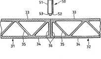
Fig. 1 is the vertical cross-section of a certain embodiment of the present invention.
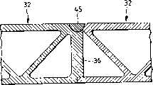
Fig. 2 is the vertical cross-section of Fig. 1 after friction welding.
Fig. 3 is the vertical cross-section of another embodiment of the present invention.
Fig. 4 is the vertical cross-section of Fig. 3 after friction welding.
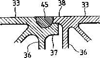
Fig. 5 is the vertical cross-section of further embodiment of this invention.
Fig. 6 is the friction welding vertical cross-section afterwards of Fig. 5.
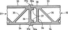
Fig. 7 is the vertical cross-section of yet another embodiment of the invention.
Fig. 8 is the vertical cross-section of Fig. 7 after friction welding.
Fig. 9 is the vertical cross-section of expression as friction welding process as described in further embodiment of this invention.
Figure 10 is the vertical cross-section of further embodiment of this invention.
Figure 11 is the vertical cross-section of further embodiment of this invention.
Figure 12 is the vertical cross-section of further embodiment of this invention.
Figure 13 is the vertical cross-section of further embodiment of this invention.
Figure 14 is the vertical cross-section of further embodiment of this invention.
Figure 15 is the vehicle body transparent view that railway vehicle is arranged.
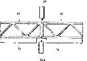
In the embodiment shown in fig. 1, the joint design that has butt joint type between thehollow member hollow member diaphragm plate 36,36.Diaphragm plate Diaphragm plate protuberance 52 is positioned on the extended surface at interface between twodiaphragm plates 36,36.The rigidity ofdiaphragm plate Diaphragm plate 36 is perpendicular to other two boards spare 33,34.Hollowmember hollow member 31 and lower surface and the hollow member 32.That ishollow member path protuberance 52 betweenedge 53 be positioned at the top ofhollow member upper surfaces.Identifier 35 expression is used for several members of connecting two boards spare 33,34 and being provided with the truss structure form.Twohollow member member diaphragm plate
The embodiment of friction welding is: makeinstrument 50 rotation,protuberance 52 is inserted the joint area ofhollow member protuberance 52 is moved along joint area.The center of turn axis ofprotuberance 52 is positioned between twodiaphragm plates
Fig. 2 represents two through the panelling after the friction welding.The welding bead thatidentifier 45 expression welding backs form.The width ofwelding bead 45 is centered close on the extended line ofdiaphragm plate lines.Welding bead 45 is positioned in the interior a certain zone ofdiaphragm plate bottom protuberances 52 insert in the joint area.
In this structure, supporting the vertical force that produces in the friction welding process perpendicular to thediaphragm plate plate diaphragm plate 36 as much as possible perpendicular toplate
Can punch on thediaphragm plate 36, with expendable weight, hereinafter described embodiment also is like this.
The welding hollow member can spin upside down it during the bottom side.
In the embodiment shown in fig. 3, the end of a certainhollow member 31 is provided withdiaphragm plate 36, and the corresponding end of anotherhollow member 32 does not have.On thediaphragm plate 36 ofhollow member 31, otch is made in the bight on its vertical direction, can rabbet the end ofexcrescence hollow member 32 thus.This notch portion is opened along the vertical direction (towardshollow member 32 1 sides) of the thickness direction and the thickness of hollow member 31.Whenexcrescence 38 is placed (nested) in notch portion the time, leave certain clearance between the two, be contacted each other although it seems in the drawings.(beingexcrescence hollow member diaphragm plate 36 upper surfaces one side partly is located immediately at the below of throw 50 central axis.The centre of gration axis of solderingoutfit 50protuberances 52 is arranged in the extended line ofdiaphragm plate 36 mid-depth lines.That is to say that the joint area of plate 33 (34) and plate 34 (33) is positioned on the extended line ofdiaphragm plate 36 mid-depth lines.Extend to the arm ofangle 33b of notch portion fromplate diaphragm plate 36 mid-depth lines.Consider arm ofangle 33b, the gap between 34b and theexcrescence 38, arm ofangle 33b, the 34b position should be partial to the left side ofdiaphragm plate 36 mid-depth line extended lines slightly.The rigidity ofdiaphragm plate 36 should be enough to bear down drive.Horizontal clearance betweenexcrescence 38 front ends and thehollow member 31 is same as situation shown in Figure 1.The height of solderingoutfit 50protuberances 52 and the thickness ofexcrescence 38 are about equally.The plastic flow zone forms the zone greater than protuberance 25 diameters gradually in the expansion ofexcrescence 38 downsides, finishes the friction welding of twohollow member excrescence 38 downsides and diaphragm plates, the friction welding seam that its downside also must distribute and form in a manner described.
Joint situation after Fig. 4 represents to weld.The shaping characteristic ofwelding bead 45 is: its width is centered close on the extended line ofdiaphragm plate
In order to bear vertical force, the centre of gration axis ofinstrument 50 is positioned on the extended line ofdiaphragm plate hollow member angle diaphragm plate protuberance 52 ofinstrument 50 is positioned at the scope ofdiaphragm plate 36 thickness extended lines, and the thickness ofdiaphragm plate 36 depends on the size of vertical force, the position ofprotuberance 52 and the intensity of diaphragm plate 36.Therefore,diaphragm plate 36 thickness exist less than the situation ofprotuberance 52 diameters.In view ofthrow 50 and arm ofangle 33b, the positional error that 34b may exist should make arm ofangle diaphragm plate 36 thickness extended lines, andprotuberance 52 also should have at least a part to be positioned at this scope.This set can makediaphragm plate 36 bear a part of vertical force at least, thereby achieves a butt joint a deformed configurations prevention substantially.So just can obtain satisfied welding effect.With regard towelding bead 45, even its size is slightly larger thanprotuberance 52, above-mentioned conclusion remains actv..Like this too for other embodiment.
Compare with situation shown in Figure 1, even this joint design when the gap is big betweenexcrescence 38 andhollow member 31, also can make the surface depression of the joint area degree that minimizes.These characteristics can make this joint obtain presentation quality preferably, and can reduce the putty consumption when spraying paint.Its reason is, the gap between two members ends on the depth location that equates withexcrescence 38 thickness.Also it may be noted that: this joint design can expendable weight.In addition, owing to two hollow member are rabbeted each other, so the two location on short transverse also is easy to realize.
The end ofhollow member 31 has the shape of both sides symmetry.Hollowmember 32 also is the both sides symmetry.In addition, an end ofhollow member 31 can be a shape shown in Figure 3, and its other end then can be made the shape of hollow member shown in Figure 3 32 ends.
In the embodiment shown in fig. 5, the arm ofangle 33b ofhollow member 31 upper cuts part, in fact the 34b downside directly is not provided with diaphragm plate 36.The right-hand member ofdiaphragm plate 36 is positioned at arm ofangle 33b, on the extendible portion of 34b.The centre of gration axis ofinstrument 50 is aimed at this extendible portion.The end ofhollow member 31 should have the rigidity that is enough to bear vertical force, for this reason, can thicken thedownside excrescence 37 of joint and increase knuckle size from the leading section ofexcrescence 37 to diaphragm plate 36.As above embodiment shown in Figure 3, theexcrescence 38 of anotherhollow member 32 can embed in the notch portion of excrescence 37.Be provided with thediaphragm plate 36 that is used for connectingupside plate 33 anddownside plate 34 near theexcrescence 38 of second hollow member 32.For this set, even there is notdiaphragm plate 36 under the arm of angle of notch portion, defective can not appear in the joint area yet.But it may be noted thatwelding bead 45 downsides are provided with thediaphragm plate 36 of plate 31.Fig. 6 has represented the situation after the welding.
In the embodiment shown in fig. 5, theplate 36 ofhollow member 32 can be removed.
Fig. 7 represents another embodiment as remodeling embodiment illustrated in fig. 5, and wherein, the joint area of twohollow member projection 37a, 38a.This can make joint area thicken.Twoprojection 37a, the height of 38a equates.Except thatdiaphragm plate 36 andprotuberance 37 were thin slightly, the other parts of this structure were same as structure shown in Figure 5.
Concerning this structure, if there is the gap in twoprojection 37a before welding between the 38a, when welding, just need so to useprojection 37a, the material of 38a is filled this gap, can improve presentation quality thus and reduce the putty consumption.
In normal weld, following drive flows downward material 41, the sunk part in the welding bead just corresponding the material 41 formed space of running off.In joint design shown in Figure 7, throw makesoutshot 37a, and the 38a plasticizing also forces it to remedy the loss space of material 41.So just, avoid forming depression, thereby obtained satisfied welding joint.Welding bead 45 shapes after Fig. 8 represents to weld.If have redundance after the welding, can be as shown in the figure with its excision.
Fig. 9 represents another embodiment, and this embodiment only allows from a side welding in upper and lower surface.The end ofhollow member downside plate upside plate downside plate 34,34.The front end ofupside plate diaphragm plate downside plate 34,34.Diaphragmplate diaphragm plate upside plate 33,33.The distance that two diaphragm plates are 36,36 should be as far as possible little, but also should be enough to guarantee the insertion of throw 50.The relation thatdiaphragm plate
Below introduce welding process.Under state shown in Fig. 9 (A), with the front end ofthrow 50 welding downside plates.At this moment, the joint area that comprisesplate hollow member 31,32.The upper surface of underframe (being the welding bead behind) is the plane.The height of theprotuberance 52 ofthrow 50 is less than the thickness ofplate 34,34.This design can guarantee that the bottom surface is still smooth after welding.Therefore, bottom surface one side can be used as the outside face (this outside face is meant the surface of being unkitted trim board) of railway vehicle or building structure undoubtedly.Usually, the upper surface in friction welding district (in the marginal portion 51) is not easy to smooth.
After this, shown in Fig. 9 (B), attaching parts 60 is contained between twohollow member
Then, shown in Fig. 9 (C), carry out friction welding with the blank area between 50 pairs of attaching partss 60 of throw and the hollow member 31.It is identical with used instrument among Fig. 9 (A) that throw 50 need not.
Then, shown in Fig. 9 (D), carry out friction welding with the blank area between 50 pairs of attaching partss 60 of throw and thehollow member 32.
Said method allows to weld from a side, thereby has removed turning operation.The advantage of removing turning operation has been to save upset and positioning action required man-hour, and has saved turning device, and assembly precision also and then be improved.
Figure 10 represents another embodiment, has wherein adopted the method for the both sides up and down ofhollow member throw 50a that is used for downside arranges in the vertical lower of the used solderingoutfit 50 of upside.Theprotuberance 52 ofsecond soldering outfit 50a is towards the top.Twosoldering outfits 50 toward each other, 50a move with identical speed when carrying outfriction welding.Identifier instrument hollow member
Adopt this layout that the centre of gration axis of thesecond instrument 50a is positioned on the extended line of first instrument, 50 centre of gration axis, the mechanical balance of the two helps smaller in the short period of time distortion to finish the welding of joint.In addition, owing to need not turninghollow member
This embodiment also is applicable to other embodiment.
The various embodiments described above are panelling to be welded with hollow member.Embodiment hereinafter is applicable to introduction the friction welding method of honeycomb type panelling.As shown in figure 11,honeycomb type panelling edge member 84 of surface panel 81,82 edge placement, wherein, arbor member 83 andedge member 84 are welded on the surface panel 81,82 by fibre, thereby form an integral structure.Surface panel 81,82, arbor member 83 andedge member 84 are made by aluminumalloy.Edge member 84 is for extrusion molding spare and have the square-section.The thickness on each bar limit is all greater than the thickness of surface panel 81,82 on this square-section.Be similar to situation shown in Figure 1, for twoedge members honeycomb type panelling
Embodiment illustrated in fig. 11 corresponding to embodiment illustrated in fig. 1.The height ofthrow 50protuberances 52 is greater than the thickness of surface panel 81,82.Be convenient to like this surface panel 81,82 andedge member panelling 80a, the load on the 80b is mainly transmitted by edge member 84.To thepanelling 80a that has completed, 80b can assemble and friction welding.
Embodiment illustrated in fig. 12 corresponding to embodiment illustrated in fig. 3.Theedge member 84 ofhoneycomb type panelling 80a has the cross section that is roughly rectangle, and arm of angle place is provided with otch.Theedge member 84 ofhoneycomb type panelling 80b then resembles the pipeline of an opening towards honeycomb type panelling 80a.The open end ofedge member 84 is connected on the notch portion ofedge member 84 ofhoneycomb type panelling 80a.
Can be by with the quadrat method manufacturing corresponding to the honeycomb type panelling of Fig. 5.
Figure 13 represents another embodiment corresponding to Fig. 7.Assembling twohoneycomb type panelling 80a, after the 80b, plate 86 is being placed on the surface panel 81,81 and temporarily it is welded on the surface panel 81,81.Plate 86 can be compensated plasticizing and the material that flows out.The vertical component of the edge member ofhoneycomb type panelling 80a shown in Figure 12 has been removed, vertical force by the horizontal component ofedge member 84 and on every side other parts bear.
Figure 14 represents an alternative embodiment of the invention.Figure 13 and before each embodiment in, panelling has two surfaces (surface panel), and in fact thepanelling panelling projection control soldering outfit 50 height.Plate 93,93 motions surfacewise of the mobile vehicle of instrument 50.Because the existence of surface panel 93 and 94 we can say thatpanelling surface texture.Panelling 91,92nd, the extrusion molding member.
Figure 14 has represented twopanellings 91 respect to one another and 92 diaphragm plates 96,96 in its connector portions office, and its similar is in Fig. 1, but also can take Fig. 3 to this, and the mode shown in 5 and 7 also is about to diaphragm plate and assembles up each other.
Figure 15 represents that this embodiment is at the structural application example of rail motorcar body.This body structure hassidepiece vehicle body 101,roof structure 102,base arrangement 103 and outer in theangular structure 104 of longitudinal end.Sidepiecevehicle body 101 androof structure 102 have used long limit to point to thepanelling sidepiece vehicle body 101 and theroof structure 102 and betweensidepiece vehicle body 101 and thebase arrangement 103 realizes.Roof structure 102 andsidepiece vehicle body 101 are generally made arc section.When doingsidepiece vehicle body 101 withpanelling
Claims (3)
1. the structure of a rolling stock is characterized in that:
Described rolling stock has a side portion structure body, a roof structure body and an end construction body;
Described side portion structure body is by arranging that a plurality of members carry out friction welding and form; And
Described side portion structure body is to adopt the metal inert-gas welding bonded assembly with being connected of roof structure body.
2. the structure of a rolling stock is characterized in that:
Described rolling stock has a side portion structure body, a roof structure body and a base arrangement body;
Described side portion structure body is by arranging that a plurality of members carry out friction welding and form; And
Described side portion structure body is to adopt the metal inert-gas welding bonded assembly with being connected of base arrangement body.
3. the structure of a rolling stock is characterized in that:
Described rolling stock has a side portion structure body, a roof structure body and an end construction body;
Described side portion structure body and roof structure body are all by arranging that a plurality of members carry out friction welding and form; And
Described side portion structure body is to adopt the metal inert-gas welding bonded assembly with being connected of roof structure body.
Applications Claiming Priority (2)
| Application Number | Priority Date | Filing Date | Title |
|---|---|---|---|
| JP6249196 | 1996-03-19 | ||
| JP62491/1996 | 1996-03-19 |
Related Parent Applications (1)
| Application Number | Title | Priority Date | Filing Date |
|---|---|---|---|
| CNB971034974ADivisionCN1203954C (en) | 1996-03-19 | 1997-03-18 | Friction Stir Welding Method |
Publications (1)
| Publication Number | Publication Date |
|---|---|
| CN1322650Atrue CN1322650A (en) | 2001-11-21 |
Family
ID=13201704
Family Applications (20)
| Application Number | Title | Priority Date | Filing Date |
|---|---|---|---|
| CNB011114983AExpired - Fee RelatedCN1165403C (en) | 1996-03-19 | 1997-03-18 | Components for friction welding |
| CNB2004101046013AExpired - Fee RelatedCN1322241C (en) | 1996-03-19 | 1997-03-18 | Friction welding method and structure body formed by friction welding |
| CNB2006100943947AExpired - Fee RelatedCN100441935C (en) | 1996-03-19 | 1997-03-18 | panel structure |
| CNB2004101046719AExpired - Fee RelatedCN1322242C (en) | 1996-03-19 | 1997-03-18 | Structure for friction welding |
| CNB2006100998206AExpired - Fee RelatedCN100475411C (en) | 1996-03-19 | 1997-03-18 | Friction welding method and structure using the friction welding method |
| CNB2006100943932AExpired - Fee RelatedCN100531997C (en) | 1996-03-19 | 1997-03-18 | Panel Construct |
| CN2006100943928AExpired - Fee RelatedCN1880002B (en) | 1996-03-19 | 1997-03-18 | Friction Stir Welding Method |
| CNB971034974AExpired - Fee RelatedCN1203954C (en) | 1996-03-19 | 1997-03-18 | Friction Stir Welding Method |
| CNB2004100949164AExpired - Fee RelatedCN1310732C (en) | 1996-03-19 | 1997-03-18 | Friction welding method |
| CNB991084934AExpired - Fee RelatedCN1208165C (en) | 1996-03-19 | 1999-06-18 | Structure and vehicle manufacturing method |
| CNB011118059AExpired - Fee RelatedCN1208166C (en) | 1996-03-19 | 2001-03-16 | Structural body mfg. method and structural body |
| CNB011118024AExpired - Fee RelatedCN1203957C (en) | 1996-03-19 | 2001-03-16 | Friction welding method and structure using the friction welding method |
| CNB011118075AExpired - Fee RelatedCN1199756C (en) | 1996-03-19 | 2001-03-16 | Structural member for friction welding |
| CNB011118032AExpired - Fee RelatedCN1211180C (en) | 1996-03-19 | 2001-03-16 | Hollow structural member for friction welding |
| CNB011118016AExpired - Fee RelatedCN1203956C (en) | 1996-03-19 | 2001-03-16 | Friction welding method |
| CNB011114967AExpired - Fee RelatedCN1192847C (en) | 1996-03-19 | 2001-03-16 | Friction welding method and structural body |
| CNB011118067AExpired - Fee RelatedCN1208167C (en) | 1996-03-19 | 2001-03-16 | Structural member for friction welding |
| CN01111497APendingCN1322650A (en) | 1996-03-19 | 2001-03-16 | Structural body of railway stock |
| CN011118040AExpired - Fee RelatedCN1216713C (en) | 1996-03-19 | 2001-03-16 | Friction welding method |
| CNB011114991AExpired - Fee RelatedCN1192848C (en) | 1996-03-19 | 2001-03-16 | Method of friction welding and structural body |
Family Applications Before (17)
| Application Number | Title | Priority Date | Filing Date |
|---|---|---|---|
| CNB011114983AExpired - Fee RelatedCN1165403C (en) | 1996-03-19 | 1997-03-18 | Components for friction welding |
| CNB2004101046013AExpired - Fee RelatedCN1322241C (en) | 1996-03-19 | 1997-03-18 | Friction welding method and structure body formed by friction welding |
| CNB2006100943947AExpired - Fee RelatedCN100441935C (en) | 1996-03-19 | 1997-03-18 | panel structure |
| CNB2004101046719AExpired - Fee RelatedCN1322242C (en) | 1996-03-19 | 1997-03-18 | Structure for friction welding |
| CNB2006100998206AExpired - Fee RelatedCN100475411C (en) | 1996-03-19 | 1997-03-18 | Friction welding method and structure using the friction welding method |
| CNB2006100943932AExpired - Fee RelatedCN100531997C (en) | 1996-03-19 | 1997-03-18 | Panel Construct |
| CN2006100943928AExpired - Fee RelatedCN1880002B (en) | 1996-03-19 | 1997-03-18 | Friction Stir Welding Method |
| CNB971034974AExpired - Fee RelatedCN1203954C (en) | 1996-03-19 | 1997-03-18 | Friction Stir Welding Method |
| CNB2004100949164AExpired - Fee RelatedCN1310732C (en) | 1996-03-19 | 1997-03-18 | Friction welding method |
| CNB991084934AExpired - Fee RelatedCN1208165C (en) | 1996-03-19 | 1999-06-18 | Structure and vehicle manufacturing method |
| CNB011118059AExpired - Fee RelatedCN1208166C (en) | 1996-03-19 | 2001-03-16 | Structural body mfg. method and structural body |
| CNB011118024AExpired - Fee RelatedCN1203957C (en) | 1996-03-19 | 2001-03-16 | Friction welding method and structure using the friction welding method |
| CNB011118075AExpired - Fee RelatedCN1199756C (en) | 1996-03-19 | 2001-03-16 | Structural member for friction welding |
| CNB011118032AExpired - Fee RelatedCN1211180C (en) | 1996-03-19 | 2001-03-16 | Hollow structural member for friction welding |
| CNB011118016AExpired - Fee RelatedCN1203956C (en) | 1996-03-19 | 2001-03-16 | Friction welding method |
| CNB011114967AExpired - Fee RelatedCN1192847C (en) | 1996-03-19 | 2001-03-16 | Friction welding method and structural body |
| CNB011118067AExpired - Fee RelatedCN1208167C (en) | 1996-03-19 | 2001-03-16 | Structural member for friction welding |
Family Applications After (2)
| Application Number | Title | Priority Date | Filing Date |
|---|---|---|---|
| CN011118040AExpired - Fee RelatedCN1216713C (en) | 1996-03-19 | 2001-03-16 | Friction welding method |
| CNB011114991AExpired - Fee RelatedCN1192848C (en) | 1996-03-19 | 2001-03-16 | Method of friction welding and structural body |
Country Status (6)
| Country | Link |
|---|---|
| US (24) | US6581819B1 (en) |
| EP (18) | EP0797043B1 (en) |
| JP (7) | JP2000202652A (en) |
| KR (13) | KR100445140B1 (en) |
| CN (20) | CN1165403C (en) |
| DE (17) | DE69739569D1 (en) |
Cited By (2)
| Publication number | Priority date | Publication date | Assignee | Title |
|---|---|---|---|---|
| CN102019936A (en)* | 2009-09-16 | 2011-04-20 | 阿尔斯通运输股份有限公司 | Method for assembling railway vehicle and railway vehicle obtained by applying method |
| CN108723578A (en)* | 2018-07-18 | 2018-11-02 | 中车长春轨道客车股份有限公司 | The friction stir welding method of hollow aluminium section bar split arc plate |
Families Citing this family (180)
| Publication number | Priority date | Publication date | Assignee | Title |
|---|---|---|---|---|
| CN1165403C (en)* | 1996-03-19 | 2004-09-08 | 株式会社日立制作所 | Components for friction welding |
| JP3897391B2 (en)* | 1997-03-25 | 2007-03-22 | 昭和電工株式会社 | Friction stir welding method for metal joining members |
| GB9713209D0 (en)* | 1997-06-20 | 1997-08-27 | British Aerospace | Friction welding metal components |
| JP3070735B2 (en) | 1997-07-23 | 2000-07-31 | 株式会社日立製作所 | Friction stir welding method |
| JP3589863B2 (en) | 1997-07-23 | 2004-11-17 | 株式会社日立製作所 | Structure and friction stir welding method |
| SE9704800D0 (en)* | 1997-12-19 | 1997-12-19 | Esab Ab | Device for welding |
| US6051325A (en)* | 1997-12-23 | 2000-04-18 | Mcdonnell Douglas Corporation | Joining of machined sandwich assemblies by friction stir welding |
| US6745929B1 (en)* | 1998-06-16 | 2004-06-08 | Hitachi, Ltd. | Method of manufacturing structural body and structural body |
| JP3420502B2 (en)* | 1998-06-16 | 2003-06-23 | 株式会社日立製作所 | Structure |
| US6045028A (en) | 1998-07-17 | 2000-04-04 | Mcdonnell Douglas Corporation | Integral corrosion protection of friction-welded joints |
| AU733140B2 (en)* | 1998-09-29 | 2001-05-10 | Hitachi Limited | A friction stir welding method |
| JP3459193B2 (en) | 1999-05-26 | 2003-10-20 | 株式会社日立製作所 | Method of repairing friction stir welding and method of manufacturing railway vehicle |
| TW460346B (en)* | 1999-05-28 | 2001-10-21 | Hitachi Ltd | A manufacturing method of a structure body and a manufacturing apparatus of a structure body |
| TW464576B (en) | 1999-05-28 | 2001-11-21 | Hitachi Ltd | A structure body and a manufacturing method of a structure body |
| JP3481501B2 (en) | 1999-05-28 | 2003-12-22 | 株式会社日立製作所 | Structure and method of manufacturing the same |
| JP2000343245A (en)* | 1999-05-31 | 2000-12-12 | Hitachi Ltd | How to make a structure |
| TW449519B (en) | 1999-05-31 | 2001-08-11 | Hitachi Ltd | A manufacturing method of a structure body |
| DE19948441A1 (en)* | 1999-10-08 | 2001-04-12 | Abb Research Ltd | Device for joining metal sheets, working with heat generating rotating ceramic pin |
| JP3459210B2 (en) | 1999-11-24 | 2003-10-20 | 株式会社日立製作所 | Friction stir welding method |
| JP3538357B2 (en)* | 2000-01-24 | 2004-06-14 | 株式会社日立製作所 | Friction stir welding method |
| AU757401B2 (en)* | 2000-01-27 | 2003-02-20 | Hitachi Limited | Structure body |
| JP3552978B2 (en) | 2000-01-27 | 2004-08-11 | 株式会社日立製作所 | Hollow profile |
| JP3571601B2 (en)* | 2000-02-21 | 2004-09-29 | 株式会社日立製作所 | Friction stir welding method |
| JP3589930B2 (en)* | 2000-02-25 | 2004-11-17 | 株式会社日立製作所 | Friction stir welding method |
| JP3575748B2 (en) | 2000-03-06 | 2004-10-13 | 株式会社日立製作所 | Friction stir welding method |
| MXPA02010936A (en) | 2000-05-08 | 2004-09-06 | Univ Brigham Young | Friction stir weldin of metal matrix composites, ferrous alloys, non ferrous alloys, and superalloys using a superabrasive tool. |
| JP3781099B2 (en)* | 2000-06-02 | 2006-05-31 | トヨタ自動車株式会社 | Hollow product, fluid processing system, and method for joining hollow members |
| US6352193B1 (en) | 2000-08-01 | 2002-03-05 | General Electric Company | Apparatus for joining electrically conductive materials |
| JP2002086281A (en)* | 2000-09-13 | 2002-03-26 | Hitachi Ltd | Friction stir welding method |
| JP3818084B2 (en)* | 2000-12-22 | 2006-09-06 | 日立電線株式会社 | Cooling plate and manufacturing method thereof, and sputtering target and manufacturing method thereof |
| JP3761786B2 (en) | 2001-01-17 | 2006-03-29 | 株式会社日立製作所 | Friction stir welding method and apparatus |
| JP3751215B2 (en)* | 2001-04-16 | 2006-03-01 | 株式会社日立製作所 | Friction stir welding method |
| JP3725043B2 (en)* | 2001-04-25 | 2005-12-07 | 株式会社日立製作所 | Rail vehicle |
| US6732901B2 (en) | 2001-06-12 | 2004-05-11 | Brigham Young University Technology Transfer Office | Anvil for friction stir welding high temperature materials |
| US7152909B2 (en)* | 2001-06-22 | 2006-12-26 | East Manufacturing Corporation | Trailer and trailer body construction and extruded panel for same |
| JP2003095097A (en) | 2001-09-25 | 2003-04-03 | Hitachi Ltd | Rail vehicle |
| JP3725057B2 (en) | 2001-09-25 | 2005-12-07 | 株式会社日立製作所 | Rail vehicle |
| DE20200646U1 (en)* | 2002-01-17 | 2003-06-05 | Horst Witte Entwicklungs- und Vertriebs-KG, 21369 Nahrendorf | Sandwich panel for making workpiece clamping devices, comprises hollow profiles joined together by friction welding |
| DE20202108U1 (en)* | 2002-02-13 | 2003-06-26 | Horst Witte Entwicklungs- und Vertriebs-KG, 21369 Nahrendorf | Sandwich panel to build up workpiece fixtures |
| DE10226526A1 (en)* | 2002-06-14 | 2003-08-07 | Daimler Chrysler Ag | Running gear frame has interconnected frame sections with at least one frame section seam as a friction stir welded seam which extends three-dimensionally, and at least two frame sections are differently constructed |
| JP4647179B2 (en)* | 2002-09-11 | 2011-03-09 | 株式会社日立製作所 | Processing method |
| JP2006518671A (en) | 2003-01-30 | 2006-08-17 | スミス インターナショナル、インコーポレテッド | Out-of-position friction stir welding of high melting point materials |
| US7430888B2 (en)* | 2003-04-25 | 2008-10-07 | Showa Denko K.K. | Tubular metal body, method of producing same, liner for pressure vessel and method of producing same |
| WO2004101205A2 (en) | 2003-05-05 | 2004-11-25 | Smith International, Inc. | Applications of friction stir welding using a superabrasive tool |
| US6893594B2 (en)* | 2003-06-20 | 2005-05-17 | Kuei Yung Wang Chen | Extruded window and door composite frames |
| US6933057B2 (en)* | 2003-07-17 | 2005-08-23 | The Boeing Company | Friction stir welded assembly and method of forming a friction stir welded assembly |
| US7225968B2 (en) | 2003-08-04 | 2007-06-05 | Sii Megadiamond, Inc. | Crack repair using friction stir welding on materials including metal matrix composites, ferrous alloys, non-ferrous alloys, and superalloys |
| US7494040B2 (en)* | 2003-09-25 | 2009-02-24 | Sii Megadiamond, Inc. | Friction stir welding improvements for metal matrix composites, ferrous alloys, non-ferrous alloys, and superalloys using a superabrasive tool |
| US7225967B2 (en) | 2003-12-16 | 2007-06-05 | The Boeing Company | Structural assemblies and preforms therefor formed by linear friction welding |
| US7398911B2 (en)* | 2003-12-16 | 2008-07-15 | The Boeing Company | Structural assemblies and preforms therefor formed by friction welding |
| GB0329898D0 (en)* | 2003-12-23 | 2004-01-28 | Airbus Uk Ltd | Welding process for large structures |
| KR100608712B1 (en)* | 2004-01-06 | 2006-08-03 | 삼성전자주식회사 | Image data display device and display method |
| CA2492185A1 (en)* | 2004-01-08 | 2005-07-08 | Tecton Products | Pultruded building product |
| US20050166516A1 (en)* | 2004-01-13 | 2005-08-04 | Valinge Aluminium Ab | Floor covering and locking systems |
| US20050199372A1 (en)* | 2004-03-08 | 2005-09-15 | Frazer James T. | Cold plate and method of making the same |
| US20050210820A1 (en)* | 2004-03-24 | 2005-09-29 | Shinmaywa Industries, Ltd. | Frame and method for fabricating the same |
| US8186561B2 (en) | 2004-03-24 | 2012-05-29 | Megastir Technologies, LLC | Solid state processing of hand-held knife blades to improve blade performance |
| JP4485846B2 (en)* | 2004-05-11 | 2010-06-23 | 株式会社日立製作所 | Structure block manufacturing method and manufacturing apparatus |
| US7520099B2 (en)* | 2004-05-17 | 2009-04-21 | Tecton Products | Pultruded building product and system |
| US20050262791A1 (en)* | 2004-05-17 | 2005-12-01 | Todd Pringle | Siding and building product |
| US20060049234A1 (en)* | 2004-05-21 | 2006-03-09 | Flak Richard A | Friction stirring and its application to drill bits, oil field and mining tools, and components in other industrial applications |
| US20100078224A1 (en) | 2004-05-21 | 2010-04-01 | Smith International, Inc. | Ball hole welding using the friction stir welding (fsw) process |
| US7188686B2 (en)* | 2004-06-07 | 2007-03-13 | Varco I/P, Inc. | Top drive systems |
| JP4695355B2 (en)* | 2004-07-15 | 2011-06-08 | 新日本製鐵株式会社 | Boom / arm member for construction machine with excellent weld fatigue strength and method for manufacturing the same |
| US7841504B2 (en)* | 2004-09-21 | 2010-11-30 | The Boeing Company | Apparatus and system for welding self-fixtured preforms and associated method |
| CN100584510C (en)* | 2004-10-05 | 2010-01-27 | Sii米加钻石公司 | Expandable mandrel for use in friction stir welding and method of providing the mandrel |
| FR2879548B1 (en)* | 2004-12-17 | 2007-02-16 | Alstom Transport Sa | PANEL ASSEMBLY FOR THE CONSTRUCTION OF A RAIL VEHICLE BOX AND METHOD THEREOF |
| KR100780019B1 (en)* | 2005-02-01 | 2007-11-27 | 가부시끼가이샤 히다치 세이사꾸쇼 | Friction Stir Welding |
| US7473475B1 (en)* | 2005-05-13 | 2009-01-06 | Florida Turbine Technologies, Inc. | Blind weld configuration for a rotor disc assembly |
| JP5010117B2 (en)* | 2005-07-20 | 2012-08-29 | 株式会社神戸製鋼所 | Aluminum extruded hollow panel for automobile and manufacturing method thereof |
| BRPI0520507A2 (en)* | 2005-08-19 | 2009-05-12 | Airbus Espana Sl | composite material beams with bulb |
| US9266191B2 (en) | 2013-12-18 | 2016-02-23 | Aeroprobe Corporation | Fabrication of monolithic stiffening ribs on metallic sheets |
| US9511445B2 (en) | 2014-12-17 | 2016-12-06 | Aeroprobe Corporation | Solid state joining using additive friction stir processing |
| US9511446B2 (en) | 2014-12-17 | 2016-12-06 | Aeroprobe Corporation | In-situ interlocking of metals using additive friction stir processing |
| US8632850B2 (en) | 2005-09-26 | 2014-01-21 | Schultz-Creehan Holdings, Inc. | Friction fabrication tools |
| US8550326B2 (en) | 2005-10-05 | 2013-10-08 | Megastir Technologies Llc | Expandable mandrel for use in friction stir welding |
| US8056797B2 (en) | 2005-10-05 | 2011-11-15 | Megastir Technologies | Expandable mandrel for use in friction stir welding |
| DE102005048001B4 (en)* | 2005-10-06 | 2007-06-14 | Euro-Composites S.A., Zone Industrielle | connecting element |
| JP4531671B2 (en)* | 2005-10-12 | 2010-08-25 | 株式会社神戸製鋼所 | Hollow panel and manufacturing method thereof |
| US7353978B2 (en)* | 2005-10-13 | 2008-04-08 | The Boeing Company | Method of making tailored blanks using linear friction welding |
| SE530250C2 (en)* | 2006-03-08 | 2008-04-08 | Sapa Profiler Ab | Adjustable overlap joint and construction made by the same |
| JP4266024B2 (en)* | 2006-03-28 | 2009-05-20 | 株式会社日立製作所 | Rail vehicle, manufacturing method thereof, and hollow shape material used therefor |
| GB0616324D0 (en)* | 2006-08-16 | 2006-09-27 | Airbus Uk Ltd | A cover panel for an aircraft wing and a method of forming thereof |
| US20080047222A1 (en)* | 2006-08-23 | 2008-02-28 | Lockheed Martin Corporation | Friction stir welding process having enhanced corrosion performance |
| FR2907040B1 (en) | 2006-10-13 | 2009-06-26 | Alstom Transport Sa | METHOD FOR ASSEMBLING A STRUCTURE COMPRISING AN EXTERIOR AND AN INTERIOR CONSISTING OF A PLURALITY OF DOUBLE-SKIN ELEMENTS, SUCH AS A RAILWAY VEHICLE CASE, AND STRUCTURE OBTAINED |
| JP4882004B2 (en)* | 2006-11-03 | 2012-02-22 | 株式会社東洋鋼鐵 | Manufacturing apparatus and manufacturing method for reinforcing frame for display panel using aluminum alloy extruded material |
| KR100832241B1 (en)* | 2006-11-03 | 2008-05-28 | 주식회사동양강철 | Reinforcement frame for display panel using aluminum alloy extrusion and its manufacturing method |
| JP5094140B2 (en)* | 2006-11-09 | 2012-12-12 | 日野自動車株式会社 | Member joint structure |
| JP4972417B2 (en)* | 2006-12-15 | 2012-07-11 | 日野自動車株式会社 | Member joining method and structure |
| FR2912490B1 (en) | 2007-02-09 | 2010-10-29 | Alcan Rhenalu | METAL COMPOSITE PANEL AND METHOD OF MANUFACTURE |
| DE102007010262A1 (en)* | 2007-03-02 | 2008-09-04 | Siemens Ag | Lightweight structures, for use in e.g. vehicle bodywork, comprise sandwich panel with heat-sensitive core between two outer sheets, connectors at either end of the panel being welded to it using friction stir welding |
| US20080230584A1 (en)* | 2007-03-19 | 2008-09-25 | The Boeing Company | Method for Manufacturing a Workpiece by Friction Welding to Reduce the Occurrence of Abnormal Grain Growth |
| CN103722288B (en)* | 2007-06-14 | 2016-03-16 | 日本轻金属株式会社 | Bonding method |
| US20080311421A1 (en)* | 2007-06-15 | 2008-12-18 | United Technologies Corporation | Friction stir welded structures derived from AL-RE-TM alloys |
| US7624907B2 (en)* | 2007-06-15 | 2009-12-01 | Cyril Bath Company | Linear friction welding apparatus and method |
| US20080308197A1 (en)* | 2007-06-15 | 2008-12-18 | United Technologies Corporation | Secondary processing of structures derived from AL-RE-TM alloys |
| US20080308610A1 (en)* | 2007-06-15 | 2008-12-18 | United Technologies Corporation | Hollow structures formed with friction stir welding |
| US20100068550A1 (en)* | 2007-06-15 | 2010-03-18 | United Technologies Corporation | Hollow structures formed with friction stir welding |
| CN101772395B (en)* | 2007-08-10 | 2013-01-16 | 日本轻金属株式会社 | Joining method and method for manufacturing joined structure |
| WO2009022507A1 (en)* | 2007-08-10 | 2009-02-19 | Nippon Light Metal Company, Ltd. | Joining method and method of manufacturing joint structure |
| US7856790B2 (en)* | 2007-10-10 | 2010-12-28 | Tecton Products, Llc | Pultruded building product |
| US8376453B2 (en)* | 2007-11-30 | 2013-02-19 | Kyoraku Co., Ltd. | Hollow double-walled panel and interior panel for vehicle made using same |
| US8079126B2 (en)* | 2008-01-25 | 2011-12-20 | Pratt & Whitney Rocketdyne, Inc. | Friction stir welded bladder fuel tank |
| US20090223957A1 (en) | 2008-03-06 | 2009-09-10 | Hmt,Inc. | Welded full contact floating roof and method |
| US20090235608A1 (en)* | 2008-03-19 | 2009-09-24 | Jan Kosny | Support structures formed from triangular elements |
| US7762447B2 (en) | 2008-03-20 | 2010-07-27 | Ut-Battelle, Llc | Multiple pass and multiple layer friction stir welding and material enhancement processes |
| US8100316B2 (en)* | 2008-05-29 | 2012-01-24 | Airbus Operations Gmbh | Method for joining aircraft fuselage elements by friction stir welding (fsw) |
| US10252376B2 (en)* | 2009-03-03 | 2019-04-09 | U-Haul International, Inc. | Welded lap joint with corrosive-protective structure |
| DE202009003080U1 (en)* | 2009-03-04 | 2009-04-30 | Dy-Pack Verpackungen Gustav Dyckerhoff Gmbh | paper bags |
| KR101072373B1 (en) | 2009-04-13 | 2011-10-11 | 한국철도기술연구원 | Body for railway vehicles |
| US20110079446A1 (en)* | 2009-10-05 | 2011-04-07 | Baker Hughes Incorporated | Earth-boring tools and components thereof and methods of attaching components of an earth-boring tool |
| KR101548792B1 (en) | 2009-11-02 | 2015-08-31 | 메가스터 테크놀로지스, 엘엘씨 | Out of position friction stir welding of casing and small diameter tubing or pipe |
| WO2011082311A2 (en)* | 2009-12-31 | 2011-07-07 | L.B. Foster Company | Conductor rail |
| US20110215614A1 (en)* | 2010-02-25 | 2011-09-08 | Ayyakannu Mani | Lightweight cross-car beam and method of constructing a structural member |
| NO331928B1 (en)* | 2010-03-31 | 2012-05-07 | Aker Engineering & Technology | Extruded elements |
| CN101804523B (en)* | 2010-04-23 | 2011-08-31 | 唐山轨道客车有限责任公司 | Welding method of butted section bars |
| US8881964B2 (en) | 2010-09-21 | 2014-11-11 | Ut-Battelle, Llc | Friction stir welding and processing of oxide dispersion strengthened (ODS) alloys |
| JP5237355B2 (en)* | 2010-11-26 | 2013-07-17 | 三菱重工業株式会社 | Method for manufacturing panel structure |
| CN103459081B (en)* | 2011-01-19 | 2016-05-25 | 日本轻金属株式会社 | Rotary tool unit, friction stir welding method, assembly of double-layer panels, and friction stir welding method of double-layer panels |
| CN103909343B (en)* | 2011-01-19 | 2016-04-27 | 日本轻金属株式会社 | Friction stirring connecting method |
| US20140103685A1 (en)* | 2011-02-23 | 2014-04-17 | Ayyakannu Mani | Lightweight Cross-Car Beam and Method of Construction |
| US8403390B2 (en)* | 2011-03-10 | 2013-03-26 | Shiloh Industries, Inc. | Vehicle panel assembly and method of attaching the same |
| KR101307294B1 (en)* | 2011-03-24 | 2013-09-12 | 주식회사동양강철 | Profile member for LNG storage tank of LNG carrier |
| KR101307295B1 (en)* | 2011-03-24 | 2013-09-12 | 주식회사동양강철 | Profile member assembly for LNG storage tank of LNG carrier |
| JP5575035B2 (en)* | 2011-03-29 | 2014-08-20 | 株式会社神戸製鋼所 | Car battery frame structure |
| JP5320439B2 (en)* | 2011-06-14 | 2013-10-23 | 株式会社日立製作所 | High corrosion resistance plant equipment |
| US8590767B2 (en)* | 2011-06-21 | 2013-11-26 | Research Institute Of Industrial Science & Technology | Method for welding hollow structure |
| WO2012175127A1 (en) | 2011-06-22 | 2012-12-27 | Sapa Ab | Friction stir welding tool with shoulders having different areas methods using such tool; product welded with such tool |
| US9468990B2 (en) | 2011-06-22 | 2016-10-18 | Sapa Ab | Friction stir welding tool with shoulders having different areas; methods using such tool; product welded with such tool |
| DE102011051728A1 (en)* | 2011-07-11 | 2013-01-17 | Thyssenkrupp Lasertechnik Gmbh | Method and device for producing tailor-made sheet-metal strips |
| JP5567530B2 (en)* | 2011-08-19 | 2014-08-06 | 日立オートモティブシステムズ株式会社 | Friction stir welding structure and power semiconductor device |
| US8561877B2 (en)* | 2011-10-27 | 2013-10-22 | GM Global Technology Operations LLC | Structural integrity welded assembly |
| US20130256060A1 (en)* | 2012-03-29 | 2013-10-03 | Safway Services, Llc | Scaffold Plank Structure |
| JP6047951B2 (en)* | 2012-06-29 | 2016-12-21 | スズキ株式会社 | Friction stir welding method of metal material and metal material joined body |
| RU2507113C1 (en)* | 2012-07-24 | 2014-02-20 | Федеральное государственное бюджетное образовательное учреждение высшего профессионального образования "Казанский национальный исследовательский технический университет им. А.Н. Туполева-КАИ" (КНИТУ-КАИ) | Honeycomb |
| CN103775136B (en)* | 2012-10-23 | 2015-06-10 | 中航商用航空发动机有限责任公司 | Vane |
| CN103047287B (en)* | 2012-12-31 | 2015-06-17 | 浙江工业大学 | Cone-shaped friction-free rotary air supply air floatation device |
| US20140255620A1 (en)* | 2013-03-06 | 2014-09-11 | Rolls-Royce Corporation | Sonic grain refinement of laser deposits |
| CN104235589A (en)* | 2013-06-16 | 2014-12-24 | 江苏新丽源南亚新材料有限公司 | Clamping groove type cellular board and manufacturing technology thereof |
| CN103406681A (en)* | 2013-08-09 | 2013-11-27 | 中国航空工业集团公司北京航空制造工程研究所 | Self-locking side-parting-resisting connector for stirring friction welding |
| US20180361501A1 (en)* | 2013-12-18 | 2018-12-20 | MELD Manufacturing Corporation | Meld solid-state joining of different features to cast parts |
| JP6248790B2 (en)* | 2014-05-08 | 2017-12-20 | 日本軽金属株式会社 | Friction stir welding method |
| JP6287751B2 (en)* | 2014-10-17 | 2018-03-07 | 日本軽金属株式会社 | Friction stir welding method |
| ES2809725T3 (en)* | 2015-02-24 | 2021-03-05 | Alumabridge Llc | Modular bridge deck system consisting of hollow extruded aluminum elements |
| CN107921575A (en)* | 2015-08-26 | 2018-04-17 | 日本轻金属株式会社 | Joint method, the manufacture method of liquid-cooled jacket cylinder and liquid-cooled jacket cylinder |
| CN105081596A (en)* | 2015-09-06 | 2015-11-25 | 唐山轨道客车有限责任公司 | Welding joint for friction stir welding |
| US9915046B2 (en)* | 2015-12-15 | 2018-03-13 | HFW Solutions, Inc. | Self alignment structure for applications joining extruded members |
| SE539953C2 (en)* | 2016-02-08 | 2018-02-06 | Nitiu Ab | A sandwich construction element comprising an open core structure of close packed asymmetric tetrahedrons |
| DE102016110572A1 (en)* | 2016-06-08 | 2017-12-14 | B. Braun Melsungen Ag | Medical-technical treatment chamber in lightweight construction |
| GB2552343A (en)* | 2016-07-19 | 2018-01-24 | Airbus Operations Ltd | Method of manufacturing a multi-alloy aerospace component |
| US10087618B2 (en)* | 2016-07-22 | 2018-10-02 | HFW Solutions, Inc. | System and method for interlocking structural members |
| US10549795B2 (en) | 2016-08-31 | 2020-02-04 | Wabash National L.P. | Floor assembly and floor securing apparatus |
| CN106735975B (en)* | 2016-12-19 | 2018-10-09 | 中车长春轨道客车股份有限公司 | Inboard width control method when aluminium alloy ground iron car welding of underframe |
| CA3039566C (en) | 2016-12-20 | 2021-04-13 | Michael Kloepfer | Cylindrical semi-trailer |
| CA3066401C (en) | 2016-12-20 | 2023-05-02 | Titan Trailers Inc. | Cylindrical cargo container construction |
| CN106801473B (en)* | 2017-03-24 | 2023-01-31 | 广东铝遊家科技有限公司 | Aluminum alloy structure house |
| JP2019025490A (en)* | 2017-07-25 | 2019-02-21 | 日本軽金属株式会社 | Joining method |
| US10759009B2 (en)* | 2017-09-11 | 2020-09-01 | Hitachi Automotive Systems Americas, Inc. | Friction stir welding flash and burr control |
| AU2018338411B2 (en) | 2017-09-22 | 2022-11-10 | Titan Trailers Inc. | Quasi-cylindrical cargo container and construction |
| CN107503439A (en)* | 2017-10-11 | 2017-12-22 | 广东铝遊家科技有限公司 | Aluminium alloy structure mobile house |
| JP7089034B2 (en) | 2017-10-31 | 2022-06-21 | メルド マニファクチャリング コーポレーション | Solid-state laminated modeling system as well as material composition and structural background |
| CN107989277B (en)* | 2017-12-30 | 2024-01-23 | 贵阳铝镁设计研究院有限公司 | Novel aluminum alloy structure wide goose plate |
| JP6681941B2 (en)* | 2018-05-31 | 2020-04-15 | 株式会社Uacj | Shock absorber |
| CN108644602A (en)* | 2018-06-28 | 2018-10-12 | 太仓新浏精密五金有限公司 | Die casting plank |
| DE102018211574B4 (en)* | 2018-07-12 | 2022-06-30 | Thyssenkrupp Ag | workpiece group |
| USD880006S1 (en)* | 2018-08-17 | 2020-03-31 | Stage FX, Inc. | Truss |
| CN109296927B (en)* | 2018-10-31 | 2021-11-23 | 河北金维重工有限公司 | Integral sweep with high welding precision |
| CN109797905A (en)* | 2019-01-04 | 2019-05-24 | 中国华冶科工集团有限公司 | A kind of tube truss structure primary and secondary truss mutually passes through installation method |
| CN109835359B (en)* | 2019-03-07 | 2020-04-28 | 中车株洲电力机车有限公司 | Aluminum-based composite material rail vehicle |
| CN110126861A (en)* | 2019-05-08 | 2019-08-16 | 中车青岛四方机车车辆股份有限公司 | The roof side rail of vehicle |
| US11541440B2 (en) | 2019-07-25 | 2023-01-03 | National Research Council Of Canada | Snap-fit extrusions for forming panels |
| US11701737B2 (en) | 2019-09-10 | 2023-07-18 | Qingdao Cimc Reefer Trailer Co., Ltd. | Friction-stir-welded sheet-and-post sidewall |
| CN111014937B (en)* | 2019-11-25 | 2021-08-03 | 长春城际轨道客车配件有限公司 | Manufacturing method of metal structural member based on friction stir welding |
| CN111692172A (en)* | 2020-06-19 | 2020-09-22 | 中车唐山机车车辆有限公司 | Connecting piece, headwall and carriage |
| US12415690B2 (en)* | 2020-07-16 | 2025-09-16 | Motis, Llc | Trussed ramp |
| US12162703B2 (en) | 2020-07-16 | 2024-12-10 | Motis, Llc | Combination ramp and load levelers |
| GB2601393C (en)* | 2021-06-10 | 2023-02-22 | Altro Ltd | Improvements in or relating to flooring |
| CN115162513B (en)* | 2021-08-16 | 2023-09-19 | 任建利 | Arch structure frame, multi-curved cavity wall, power generation building and colorful power generation city |
| CN115285157A (en)* | 2022-09-05 | 2022-11-04 | 中车长春轨道客车股份有限公司 | Front end structure of magnetic-levitation train and magnetic-levitation train |
| DE102024103950A1 (en)* | 2024-02-13 | 2025-08-14 | SCHÜCO International KG | Method for producing an extruded composite profile and composite profile |
Family Cites Families (168)
| Publication number | Priority date | Publication date | Assignee | Title |
|---|---|---|---|---|
| US92889A (en)* | 1869-07-20 | Improvement in corn-planters | ||
| US11673A (en)* | 1854-09-12 | Cooking stove and range | ||
| US51601A (en)* | 1865-12-19 | Improvement in sawing-machines | ||
| US69834A (en)* | 1867-10-15 | palmbe | ||
| US27154A (en)* | 1860-02-14 | Straw-ctjtteb | ||
| US69835A (en)* | 1867-10-15 | Improved washing machine | ||
| US211819A (en)* | 1879-01-28 | Improvement in harrow-teeth | ||
| US74949A (en)* | 1868-02-25 | Improved washiko-maohine | ||
| US69833A (en)* | 1867-10-15 | Improved ioe-oeeam freezer | ||
| US42293A (en)* | 1864-04-12 | Improvement in balanced valves for steam-engines | ||
| US11671A (en)* | 1854-09-12 | Improved method of | ||
| US11672A (en)* | 1854-09-12 | Coknt-sheller | ||
| US1913342A (en)* | 1930-07-03 | 1933-06-06 | Truscon Steel Co | Metal structure |
| US1954511A (en)* | 1930-08-13 | 1934-04-10 | Youngstown Sheet And Tube Co | Method and apparatus for forming welded material |
| US2177868A (en)* | 1937-06-08 | 1939-10-31 | Comb Eng Co Inc | Welded joint |
| US2284229A (en)* | 1940-08-19 | 1942-05-26 | Palmer George Vincent | Metal wall building construction |
| GB572789A (en) | 1941-10-17 | 1945-10-24 | Hans Klopstock | An improved method of joining or welding metals |
| US2457129A (en)* | 1946-02-27 | 1948-12-28 | Metal Lumber Corp Of New Jerse | Hatch cover |
| US3301147A (en)* | 1963-07-22 | 1967-01-31 | Harvey Aluminum Inc | Vehicle-supporting matting and plank therefor |
| US3269072A (en)* | 1963-08-26 | 1966-08-30 | Pullman Inc | Vehicle floor construction |
| US3397496A (en)* | 1965-02-04 | 1968-08-20 | K & Associates Inc As | Locking means for roof and wall panel construction |
| US3385182A (en)* | 1965-09-27 | 1968-05-28 | Harvey Aluminum Inc | Interlocking device for load bearing surfaces such as aircraft landing mats |
| US3443306A (en)* | 1966-08-03 | 1969-05-13 | Nooter Corp | Method of joining clad material |
| US3348459A (en)* | 1967-01-03 | 1967-10-24 | Harvey Aluminum Inc | Interlocking matting and coupling bar therefor |
| US3386221A (en)* | 1967-09-08 | 1968-06-04 | Revere Copper & Brass Inc | Lightweight panel |
| IL31940A (en)* | 1968-04-05 | 1971-08-25 | Dynamit Nobel Ag | Sections from thermoplastic resins |
| US3538819A (en)* | 1968-07-26 | 1970-11-10 | Us Navy | Airfield matting locking pin |
| SE359479B (en)* | 1972-02-24 | 1973-09-03 | Platmanufaktur Ab | |
| US3849835A (en)* | 1972-09-19 | 1974-11-26 | Acme General Corp | Spring hinge for bifold doors |
| US3848871A (en) | 1973-04-19 | 1974-11-19 | A Sweet | Non-slipping hand grip for tennis racket and the like |
| US3849871A (en)* | 1973-08-06 | 1974-11-26 | Neander H | Method for welding pipes |
| US4019018A (en)* | 1974-09-30 | 1977-04-19 | Kobe Steel Ltd. | Process for narrow gap welding of aluminum alloy thick plates |
| DE2450747C2 (en)* | 1974-10-25 | 1976-08-26 | Talbot Waggonfab | TWO-AXLE RAIL VEHICLE WITH A TWISTABLE BASE |
| JPS51111925A (en) | 1975-03-27 | 1976-10-02 | Mitsutoshi Washizu | Tone generator for gas cock |
| US3984961A (en)* | 1975-08-04 | 1976-10-12 | Fruehauf Corporation | Composite extruded floor |
| DE2604882C2 (en)* | 1976-02-07 | 1986-06-26 | Klaus 8940 Memmingen Kaspar | Drive-on area for mechanical parking facilities, ramps, lifting platforms or the like. |
| JPS52123358A (en) | 1976-04-09 | 1977-10-17 | Shigeru Kimura | Frictional welding method |
| JPS5411250A (en) | 1977-06-10 | 1979-01-27 | Japan Synthetic Rubber Co Ltd | Production of powdery food |
| US4337708A (en)* | 1980-04-11 | 1982-07-06 | Pullman Incorporated | Railway car superstructure frame |
| GB2088195B (en) | 1980-11-18 | 1984-04-18 | British United Shoe Machinery | Apparatus for use in heat setting a lasted shoe upper |
| US4488833A (en)* | 1982-04-27 | 1984-12-18 | Kaiser Aluminum & Chemical Corporation | Rapidly deployed assault vehicle surfacing or trackway system |
| JPS60166177A (en) | 1984-02-07 | 1985-08-29 | Toshiba Corp | Fit welding between different kind metal |
| DE3406609C2 (en)* | 1984-02-23 | 1998-08-06 | Magnetbahn Gmbh | Car body for passenger cars of railways, local trains, magnetic levitation trains |
| AU566257B2 (en)* | 1985-01-10 | 1987-10-15 | Hockney Pty Ltd | Table top for lorry |
| SU1393566A1 (en) | 1985-10-08 | 1988-05-07 | Производственное Объединение "Вильнюсский Завод Топливной Аппаратуры Им.50-Летия Ссср" | Method of seam friction welding |
| JPS62189251A (en)* | 1986-02-13 | 1987-08-19 | 川崎重工業株式会社 | Floor structure |
| SE457809B (en)* | 1987-05-20 | 1989-01-30 | Lars Svensson | bridge deck |
| US4966082A (en)* | 1987-10-21 | 1990-10-30 | Hitachi, Ltd. | Construction and a manufacturing method of underframe for a rolling stock |
| JPH01148655A (en)* | 1987-12-04 | 1989-06-12 | Tokyu Car Corp | Structure for joining structure body of vehicle |
| JPH01244961A (en)* | 1988-03-25 | 1989-09-29 | Hitachi Ltd | Vehicle body structure |
| JP2669535B2 (en)* | 1988-06-06 | 1997-10-29 | 株式会社日立製作所 | Railcar body |
| SU1655725A1 (en) | 1988-06-27 | 1991-06-15 | Производственное Объединение "Вильнюсский Завод Топливной Аппаратуры Им.50-Летия Ссср" | Welding method |
| JP2679817B2 (en)* | 1988-08-16 | 1997-11-19 | ジャトコ株式会社 | Coupling structure of two-part rotary drum for automatic transmission |
| DE375591T1 (en)* | 1988-12-21 | 1990-10-18 | United Technologies Corp., Hartford, Conn. | IMPROVEMENT IN WELDING WELDING THROUGH THE USE OF STACKED WALL GEOMETRY. |
| US5267515A (en)* | 1989-01-18 | 1993-12-07 | Hitachi, Ltd. | Vehicle body construction having longitudinally elongated extruded panels and continuous welds joining the panels |
| US5098007A (en) | 1989-01-18 | 1992-03-24 | Hitachi, Ltd. | Method of manufacturing a vehicle body |
| IL89005A (en)* | 1989-01-19 | 1991-11-21 | Polygal | Lightweight construction panels with interconnectable edges |
| JP2604226B2 (en) | 1989-03-20 | 1997-04-30 | 財団法人 鉄道総合技術研究所 | Railcar structure |
| US4977722A (en)* | 1989-06-14 | 1990-12-18 | Repla Limited | Frame system |
| US5199632A (en)* | 1989-06-30 | 1993-04-06 | Hitachi. Ltd. | Railway car body structures and methods of making them |
| DE69031328T2 (en) | 1989-06-30 | 1998-04-02 | Hitachi Ltd | Passenger car structures and their manufacturing processes |
| JP2533663B2 (en) | 1989-06-30 | 1996-09-11 | 株式会社日立製作所 | Railway vehicle structure |
| GB8928881D0 (en)* | 1989-12-21 | 1990-02-28 | Avon Inflatables Ltd | Inflatable boat and deck therefor |
| US5433151A (en)* | 1990-09-07 | 1995-07-18 | Hitachi, Ltd. | Railway car body structures and methods of making them using welded honeycomb panels connected in an edge to edge relation |
| US5064097A (en) | 1990-10-10 | 1991-11-12 | Water Center International Ltd. | Compact water purification and beverage dispensing apparatus |
| US5188278A (en)* | 1990-11-22 | 1993-02-23 | A & S Corporation | Friction welding method for joining a rim and a disc of a disc wheel and the apparatus therefor |
| US5204149A (en)* | 1991-01-04 | 1993-04-20 | Case Designers Corporation | Method and apparatus for making double wall containers |
| US5298098A (en)* | 1991-03-22 | 1994-03-29 | Hoedl Herbert K | Industrial pallets and methods of manufacture of panel structures |
| JPH0645340A (en) | 1991-11-12 | 1994-02-18 | Rohm Co Ltd | Semiconductor device and manufacturing method thereof |
| JP2626372B2 (en)* | 1991-11-25 | 1997-07-02 | 株式会社日立製作所 | Vehicle |
| GB9125978D0 (en)* | 1991-12-06 | 1992-02-05 | Welding Inst | Hot shear butt welding |
| USD338968S (en)* | 1991-12-26 | 1993-08-31 | Certainteed Corporation | Window component extrusion |
| FR2691937B1 (en) | 1992-06-03 | 1994-07-22 | Alsthom Gec | RAILWAY VEHICLE BODY IN STAINLESS STEEL. |
| TW276225B (en) | 1992-07-17 | 1996-05-21 | Hitachi Seisakusyo Kk | |
| JP2692505B2 (en)* | 1992-08-21 | 1997-12-17 | 株式会社日立製作所 | Vehicle repair method and vehicle |
| JP3266325B2 (en)* | 1992-09-10 | 2002-03-18 | ▲滲▼透工業株式会社 | Heat exchange backing body |
| JP2773570B2 (en) | 1992-09-18 | 1998-07-09 | 株式会社日立製作所 | Laminated panel |
| JPH06106681A (en) | 1992-09-24 | 1994-04-19 | Toppan Printing Co Ltd | Paper container |
| GB9220273D0 (en) | 1992-09-25 | 1992-11-11 | Welding Inst | Improvements relating to friction jointing and surfacing |
| GB2272725B (en) | 1992-11-19 | 1995-06-14 | Southco | Slam latch |
| IT1257961B (en)* | 1992-12-30 | 1996-02-19 | Fiat Ferroviaria Spa | CASH STRUCTURE WITH CORRUGATED STRUCTURAL PANELS FOR RAILWAY VEHICLES. |
| JP2640078B2 (en)* | 1993-02-08 | 1997-08-13 | 株式会社神戸製鋼所 | Damping profiles and structures for transport aircraft |
| JP3110195B2 (en)* | 1993-03-16 | 2000-11-20 | 積水化学工業株式会社 | Side-by-side plate |
| JPH06328273A (en)* | 1993-05-20 | 1994-11-29 | Daido Steel Co Ltd | How to join metal rods or wires |
| JP3237037B2 (en)* | 1993-06-17 | 2001-12-10 | 株式会社日立製作所 | Friction welding device |
| JP2626471B2 (en) | 1993-06-22 | 1997-07-02 | 株式会社日立製作所 | Manufacturing method of vehicle structure |
| US5476210A (en)* | 1993-06-25 | 1995-12-19 | Fuji Jukogyo Kabushiki Kaisha | Structure for joining plate elements and method for joining the same |
| JPH06156271A (en)* | 1993-06-28 | 1994-06-03 | Hitachi Ltd | Railroad car structure and method for fabricating its block |
| US5450317A (en)* | 1993-11-24 | 1995-09-12 | U S West Advanced Technologies, Inc. | Method and system for optimized logistics planning |
| US5398805A (en) | 1993-12-13 | 1995-03-21 | Interfit International, Ltd. | Wear shoe retainer for a sludge collector flight |
| DE4342786A1 (en)* | 1993-12-15 | 1995-06-22 | Lignotock Gmbh | Friction welding method for fitting connectors to decorative vehicle panels |
| JP2544706B2 (en) | 1994-03-25 | 1996-10-16 | 富国工業株式会社 | Continuous press |
| NO942790D0 (en) | 1994-03-28 | 1994-07-27 | Norsk Hydro As | Method of friction welding and device for the same |
| JPH07266068A (en) | 1994-03-30 | 1995-10-17 | Kobe Steel Ltd | Method for laser beam welding aluminum or aluminum alloy member |
| US5480317A (en)* | 1994-03-31 | 1996-01-02 | Illinois Tool Works Inc. | Socket for receiving a threaded member which prevents cross-threading |
| JPH07205807A (en)* | 1994-08-31 | 1995-08-08 | Hitachi Ltd | Railway car body |
| US5811035A (en)* | 1995-06-06 | 1998-09-22 | The Marley Cooling Tower Company | Multiple purpose panel for cooling towers |
| US5665435A (en)* | 1995-08-31 | 1997-09-09 | University Of Pittsburgh Of The Commonwealth System Of Higher Education | Method for fluorination of diamond surfaces |
| NO954273D0 (en) | 1995-10-26 | 1995-10-26 | Norsk Hydro As | Wheels Wheel |
| US5651154A (en) | 1995-11-13 | 1997-07-29 | Reynolds Metals Company | Modular bridge deck system consisting of hollow extruded aluminum elements |
| US6199340B1 (en)* | 1996-01-22 | 2001-03-13 | L.B. Plastics Limited | Modular construction element |
| US5819491A (en)* | 1996-01-22 | 1998-10-13 | L.B. Plastics Limited | Modular construction elements |
| JP3807766B2 (en) | 1996-02-20 | 2006-08-09 | 株式会社日立製作所 | Manufacturing method of railway vehicle structure |
| US5611479A (en) | 1996-02-20 | 1997-03-18 | Rockwell International Corporation | Friction stir welding total penetration technique |
| CN1165403C (en)* | 1996-03-19 | 2004-09-08 | 株式会社日立制作所 | Components for friction welding |
| US5862975A (en)* | 1996-03-20 | 1999-01-26 | The Boeing Company | Composite/metal structural joint with welded Z-pins |
| US5713507A (en) | 1996-03-21 | 1998-02-03 | Rockwell International Corporation | Programmable friction stir welding process |
| US5664826A (en)* | 1996-04-12 | 1997-09-09 | Wilkens; Arthur L. | Light weight trailer walls with smooth surfaces |
| US5769306A (en) | 1996-05-31 | 1998-06-23 | The Boeing Company | Weld root closure method for friction stir welds |
| US5718366A (en) | 1996-05-31 | 1998-02-17 | The Boeing Company | Friction stir welding tool for welding variable thickness workpieces |
| US5794835A (en) | 1996-05-31 | 1998-08-18 | The Boeing Company | Friction stir welding |
| DK174563B1 (en)* | 1996-09-06 | 2003-06-10 | Daimlerchrysler Rail Systems | Cover plate and method of making such cover plate |
| US5697511A (en) | 1996-09-27 | 1997-12-16 | Boeing North American, Inc. | Tank and method of fabrication |
| US5836029A (en)* | 1996-10-22 | 1998-11-17 | Reynolds Metals Company | Method of preparing an aluminum bridge deck and an aluminum bridge deck configuration for receiving a wearing surface |
| US5829664A (en) | 1996-11-15 | 1998-11-03 | Aluminum Company Of America | Resistance heated stir welding |
| US5836128A (en)* | 1996-11-21 | 1998-11-17 | Crane Plastics Company Limited Partnership | Deck plank |
| JPH10193143A (en)* | 1997-01-17 | 1998-07-28 | Showa Alum Corp | Friction stir welding |
| JP3283433B2 (en) | 1997-01-31 | 2002-05-20 | 住友軽金属工業株式会社 | Manufacturing method of aluminum wide profile |
| JP3897391B2 (en)* | 1997-03-25 | 2007-03-22 | 昭和電工株式会社 | Friction stir welding method for metal joining members |
| ES2174209T3 (en)* | 1997-07-17 | 2002-11-01 | Alcan Tech & Man Ag | CONSTRUCTION WITH PROFILES AND COMPOSITE PLATES. |
| JP3070735B2 (en)* | 1997-07-23 | 2000-07-31 | 株式会社日立製作所 | Friction stir welding method |
| JP3589863B2 (en)* | 1997-07-23 | 2004-11-17 | 株式会社日立製作所 | Structure and friction stir welding method |
| US6085485A (en)* | 1997-12-11 | 2000-07-11 | Murdock; Douglas G. | Load bearing pre-fabricated building construction panel |
| SE9704800D0 (en)* | 1997-12-19 | 1997-12-19 | Esab Ab | Device for welding |
| US6290117B1 (en)* | 1998-02-17 | 2001-09-18 | Hitachi, Ltd. | Friction stir welding method and friction stir welding apparatus |
| US6045027A (en)* | 1998-03-04 | 2000-04-04 | The Boeing Company | Friction stir welding interlocking joint design and method |
| JP3420502B2 (en)* | 1998-06-16 | 2003-06-23 | 株式会社日立製作所 | Structure |
| US6082810A (en)* | 1998-09-18 | 2000-07-04 | Utility Trailer Manufacturing Company | Cargo vehicle floor construction and method |
| AU733140B2 (en)* | 1998-09-29 | 2001-05-10 | Hitachi Limited | A friction stir welding method |
| CA2293907A1 (en)* | 1999-01-04 | 2000-07-04 | Sooner Trailer Manufacturing Co. | Trailer with improved double skin slat construction |
| JP3459187B2 (en)* | 1999-02-02 | 2003-10-20 | 株式会社日立製作所 | Hollow profile |
| JP3459193B2 (en)* | 1999-05-26 | 2003-10-20 | 株式会社日立製作所 | Method of repairing friction stir welding and method of manufacturing railway vehicle |
| TW464576B (en)* | 1999-05-28 | 2001-11-21 | Hitachi Ltd | A structure body and a manufacturing method of a structure body |
| JP3481501B2 (en)* | 1999-05-28 | 2003-12-22 | 株式会社日立製作所 | Structure and method of manufacturing the same |
| JP2000351365A (en)* | 1999-06-11 | 2000-12-19 | Hitachi Ltd | Car body |
| US6986452B2 (en)* | 1999-09-03 | 2006-01-17 | Lockheed Martin Corporation | Friction stir welding as a rivet replacement technology |
| AU7475200A (en)* | 1999-09-03 | 2001-04-10 | Lockheed Martin Corporation | Friction stir welding as a rivet replacement technology |
| JP3459210B2 (en)* | 1999-11-24 | 2003-10-20 | 株式会社日立製作所 | Friction stir welding method |
| US6722286B2 (en)* | 1999-12-14 | 2004-04-20 | Hitachi, Ltd. | Structure and railway car |
| JP3538357B2 (en)* | 2000-01-24 | 2004-06-14 | 株式会社日立製作所 | Friction stir welding method |
| JP3552978B2 (en)* | 2000-01-27 | 2004-08-11 | 株式会社日立製作所 | Hollow profile |
| JP3589930B2 (en)* | 2000-02-25 | 2004-11-17 | 株式会社日立製作所 | Friction stir welding method |
| US6324796B1 (en)* | 2000-04-10 | 2001-12-04 | Homeland Vinyl Products, Inc. | Modular decking planks |
| US6398883B1 (en)* | 2000-06-07 | 2002-06-04 | The Boeing Company | Friction stir grain refinement of structural members |
| US6729097B2 (en)* | 2000-10-12 | 2004-05-04 | Armstrong World Industries, Inc. | Hollow building panel having an angled support member and method of making same |
| JP3575749B2 (en)* | 2000-11-17 | 2004-10-13 | 株式会社日立製作所 | Friction stir welding method |
| JP3553012B2 (en)* | 2000-11-17 | 2004-08-11 | 株式会社日立製作所 | Friction stir welding method |
| EP1264321B1 (en)* | 2000-11-30 | 2006-08-16 | Showa Denko K.K. | Niobium powder for capacitor, sintered body thereof and capacitor using the sintered body |
| US6769595B2 (en)* | 2000-12-20 | 2004-08-03 | Alcoa Inc. | Friction plunge riveting |
| JP3675714B2 (en)* | 2000-12-20 | 2005-07-27 | 株式会社日立製作所 | Railway vehicle wife manufacturing method and rail car body |
| US6425626B1 (en)* | 2001-01-04 | 2002-07-30 | Michael Kloepfer | Truck/trailer box constructions |
| JP3761786B2 (en)* | 2001-01-17 | 2006-03-29 | 株式会社日立製作所 | Friction stir welding method and apparatus |
| USD459491S1 (en)* | 2001-01-31 | 2002-06-25 | Becht Engineering Company, Inc. | Deck slat |
| US6871600B2 (en)* | 2001-02-09 | 2005-03-29 | Trn Business Trust | Pultruded panel |
| US20020119336A1 (en)* | 2001-02-26 | 2002-08-29 | Takeshi Kawasaki | Method of friction stir welding structural body, structural body, and extruded material |
| US20040074949A1 (en)* | 2001-03-07 | 2004-04-22 | Masayuki Narita | Friction agitation joining method flat material for plastic working and closed end sleeve like body |
| US6550397B2 (en)* | 2001-03-27 | 2003-04-22 | Hitachi, Ltd. | Car body |
| JP3751215B2 (en)* | 2001-04-16 | 2006-03-01 | 株式会社日立製作所 | Friction stir welding method |
| US6669271B2 (en)* | 2001-06-22 | 2003-12-30 | East Manufacturing Corporation | Smooth side body structure and method |
| JP3751237B2 (en)* | 2001-09-03 | 2006-03-01 | 株式会社日立製作所 | Friction stir welding connection material |
| JP3725057B2 (en)* | 2001-09-25 | 2005-12-07 | 株式会社日立製作所 | Rail vehicle |
| JP3929816B2 (en)* | 2002-04-16 | 2007-06-13 | 株式会社日立製作所 | Hairline processing method |
| US6918221B2 (en)* | 2002-08-08 | 2005-07-19 | Robert M. Williams | Polymeric deck panels, deck assemblies, decks and methods for forming the same |
| JP4440522B2 (en)* | 2002-09-11 | 2010-03-24 | 株式会社日立製作所 | Hollow profile for friction stir welding |
| JP2003136258A (en)* | 2002-09-11 | 2003-05-14 | Hitachi Ltd | Friction stir welding method |
| US6739106B2 (en)* | 2002-09-12 | 2004-05-25 | Royal Group Technologies Limited | Reversible plastic building board with different colored sides |
| US6933057B2 (en)* | 2003-07-17 | 2005-08-23 | The Boeing Company | Friction stir welded assembly and method of forming a friction stir welded assembly |
| JP4205537B2 (en)* | 2003-09-04 | 2009-01-07 | 株式会社日立製作所 | Friction stir welding method |
- 1997
- 1997-03-18CNCNB011114983Apatent/CN1165403C/ennot_activeExpired - Fee Related
- 1997-03-18CNCNB2004101046013Apatent/CN1322241C/ennot_activeExpired - Fee Related
- 1997-03-18CNCNB2006100943947Apatent/CN100441935C/ennot_activeExpired - Fee Related
- 1997-03-18CNCNB2004101046719Apatent/CN1322242C/ennot_activeExpired - Fee Related
- 1997-03-18CNCNB2006100998206Apatent/CN100475411C/ennot_activeExpired - Fee Related
- 1997-03-18CNCNB2006100943932Apatent/CN100531997C/ennot_activeExpired - Fee Related
- 1997-03-18KRKR1019970009067Apatent/KR100445140B1/ennot_activeExpired - Lifetime
- 1997-03-18CNCN2006100943928Apatent/CN1880002B/ennot_activeExpired - Fee Related
- 1997-03-18USUS08/820,231patent/US6581819B1/ennot_activeExpired - Fee Related
- 1997-03-18CNCNB971034974Apatent/CN1203954C/ennot_activeExpired - Fee Related
- 1997-03-18CNCNB2004100949164Apatent/CN1310732C/ennot_activeExpired - Fee Related
- 1997-03-19EPEP97301870Apatent/EP0797043B1/ennot_activeExpired - Lifetime
- 1997-03-19EPEP02004624Apatent/EP1222997B1/ennot_activeExpired - Lifetime
- 1997-03-19DEDE69739569Tpatent/DE69739569D1/ennot_activeExpired - Lifetime
- 1997-03-19DEDE69734367Tpatent/DE69734367T2/ennot_activeExpired - Lifetime
- 1997-03-19EPEP01126189Apatent/EP1188507B1/ennot_activeExpired - Lifetime
- 1997-03-19EPEP02004626Apatent/EP1222999B1/ennot_activeExpired - Lifetime
- 1997-03-19DEDE69740067Tpatent/DE69740067D1/ennot_activeExpired - Lifetime
- 1997-03-19EPEP02004622Apatent/EP1222995B1/ennot_activeExpired - Lifetime
- 1997-03-19DEDE69732669Tpatent/DE69732669T2/ennot_activeExpired - Lifetime
- 1997-03-19EPEP01126193Apatent/EP1190808B1/ennot_activeExpired - Lifetime
- 1997-03-19DEDE69736958Tpatent/DE69736958T2/ennot_activeExpired - Lifetime
- 1997-03-19EPEP06005613Apatent/EP1679148B1/ennot_activeExpired - Lifetime
- 1997-03-19DEDE69736959Tpatent/DE69736959T2/ennot_activeExpired - Lifetime
- 1997-03-19EPEP06005612Apatent/EP1676667B1/ennot_activeExpired - Lifetime
- 1997-03-19EPEP02004618Apatent/EP1222991B1/ennot_activeExpired - Lifetime
- 1997-03-19DEDE69739407Tpatent/DE69739407D1/ennot_activeExpired - Lifetime
- 1997-03-19DEDE69735144Tpatent/DE69735144T2/ennot_activeExpired - Lifetime
- 1997-03-19DEDE69734368Tpatent/DE69734368T2/ennot_activeExpired - Lifetime
- 1997-03-19EPEP02004619Apatent/EP1222992B1/ennot_activeExpired - Lifetime
- 1997-03-19EPEP01126191Apatent/EP1190806B1/ennot_activeExpired - Lifetime
- 1997-03-19EPEP01126190Apatent/EP1190805A3/ennot_activeWithdrawn
- 1997-03-19DEDE69736017Tpatent/DE69736017T2/ennot_activeExpired - Lifetime
- 1997-03-19DEDE69732191Tpatent/DE69732191T2/ennot_activeExpired - Lifetime
- 1997-03-19EPEP01126192Apatent/EP1190807B1/ennot_activeExpired - Lifetime
- 1997-03-19DEDE69732260Tpatent/DE69732260T2/ennot_activeExpired - Lifetime
- 1997-03-19DEDE69735964Tpatent/DE69735964T2/ennot_activeExpired - Lifetime
- 1997-03-19EPEP02004623Apatent/EP1222996B1/ennot_activeExpired - Lifetime
- 1997-03-19EPEP02004621Apatent/EP1222994B1/ennot_activeExpired - Lifetime
- 1997-03-19DEDE69732670Tpatent/DE69732670T2/ennot_activeExpired - Lifetime
- 1997-03-19DEDE69735388Tpatent/DE69735388T2/ennot_activeExpired - Lifetime
- 1997-03-19DEDE69722493Tpatent/DE69722493T2/ennot_activeExpired - Lifetime
- 1997-03-19EPEP02004625Apatent/EP1222998B1/ennot_activeExpired - Lifetime
- 1997-03-19DEDE69735905Tpatent/DE69735905T2/ennot_activeExpired - Lifetime
- 1997-03-19EPEP06005615Apatent/EP1676668B1/ennot_activeExpired - Lifetime
- 1997-03-19EPEP02004620Apatent/EP1222993B1/ennot_activeExpired - Lifetime
- 1999
- 1999-06-18CNCNB991084934Apatent/CN1208165C/ennot_activeExpired - Fee Related
- 2000
- 2000-02-24JPJP2000047767Apatent/JP2000202652A/ennot_activeAbandoned
- 2000-02-24JPJP2000047585Apatent/JP2000205218A/enactivePending
- 2000-02-24JPJP2000047766Apatent/JP2000202651A/enactivePending
- 2000-02-24JPJP2000047583Apatent/JP2000205216A/enactivePending
- 2000-02-24JPJP2000047582Apatent/JP2000202650A/enactivePending
- 2000-02-24JPJP2000047584Apatent/JP2000205217A/enactivePending
- 2000-02-24JPJP2000047768Apatent/JP2000202653A/ennot_activeAbandoned
- 2001
- 2001-02-19KRKR1020010008233Apatent/KR100428552B1/ennot_activeExpired - Fee Related
- 2001-02-19KRKR1020010008235Apatent/KR100459094B1/ennot_activeExpired - Fee Related
- 2001-02-19KRKR1020010008240Apatent/KR100426025B1/ennot_activeExpired - Fee Related
- 2001-02-19KRKR1020010008232Apatent/KR100426021B1/ennot_activeExpired - Fee Related
- 2001-02-19KRKR1020010008238Apatent/KR100426023B1/ennot_activeExpired - Fee Related
- 2001-02-19KRKR1020010008234Apatent/KR100428553B1/ennot_activeExpired - Fee Related
- 2001-02-19KRKR1020010008239Apatent/KR100426024B1/ennot_activeExpired - Fee Related
- 2001-02-19KRKR1020010008229Apatent/KR100428539B1/ennot_activeExpired - Lifetime
- 2001-02-19KRKR1020010008231Apatent/KR100428544B1/ennot_activeExpired - Fee Related
- 2001-02-19KRKR1020010008237Apatent/KR100426022B1/ennot_activeExpired - Fee Related
- 2001-02-19KRKR1020010008230Apatent/KR100445136B1/ennot_activeExpired - Fee Related
- 2001-02-19KRKR1020010008236Apatent/KR100428554B1/ennot_activeExpired - Fee Related
- 2001-03-16CNCNB011118059Apatent/CN1208166C/ennot_activeExpired - Fee Related
- 2001-03-16CNCNB011118024Apatent/CN1203957C/ennot_activeExpired - Fee Related
- 2001-03-16CNCNB011118075Apatent/CN1199756C/ennot_activeExpired - Fee Related
- 2001-03-16CNCNB011118032Apatent/CN1211180C/ennot_activeExpired - Fee Related
- 2001-03-16CNCNB011118016Apatent/CN1203956C/ennot_activeExpired - Fee Related
- 2001-03-16CNCNB011114967Apatent/CN1192847C/ennot_activeExpired - Fee Related
- 2001-03-16CNCNB011118067Apatent/CN1208167C/ennot_activeExpired - Fee Related
- 2001-03-16CNCN01111497Apatent/CN1322650A/enactivePending
- 2001-03-16CNCN011118040Apatent/CN1216713C/ennot_activeExpired - Fee Related
- 2001-03-16CNCNB011114991Apatent/CN1192848C/ennot_activeExpired - Fee Related
- 2003
- 2003-06-23USUS10/600,577patent/US6983873B2/ennot_activeExpired - Fee Related
- 2003-06-23USUS10/600,576patent/US7032804B2/ennot_activeExpired - Fee Related
- 2003-06-23USUS10/600,616patent/US7114304B2/ennot_activeExpired - Fee Related
- 2003-06-23USUS10/600,607patent/US6966481B2/ennot_activeExpired - Fee Related
- 2003-06-23USUS10/600,610patent/US6946206B2/ennot_activeExpired - Fee Related
- 2003-06-23USUS10/600,617patent/US7520104B2/ennot_activeExpired - Fee Related
- 2003-06-23USUS10/600,574patent/US7416769B2/ennot_activeExpired - Fee Related
- 2003-06-23USUS10/600,608patent/US7056594B2/ennot_activeExpired - Fee Related
- 2003-06-23USUS10/600,614patent/US6840426B2/ennot_activeExpired - Fee Related
- 2003-06-23USUS10/600,613patent/US7178303B2/ennot_activeExpired - Fee Related
- 2003-06-23USUS10/600,572patent/US6862860B2/ennot_activeExpired - Lifetime
- 2003-06-23USUS10/600,611patent/US7032805B2/ennot_activeExpired - Fee Related
- 2003-06-23USUS10/600,615patent/US6978923B2/ennot_activeExpired - Fee Related
- 2003-06-23USUS10/600,573patent/US7073701B2/ennot_activeExpired - Fee Related
- 2003-06-23USUS10/600,575patent/US6953144B2/ennot_activeExpired - Fee Related
- 2003-06-23USUS10/600,618patent/US20040025741A1/ennot_activeAbandoned
- 2005
- 2005-03-21USUS11/084,020patent/US7562802B2/ennot_activeExpired - Fee Related
- 2006
- 2006-04-14USUS11/403,811patent/US7413107B2/ennot_activeExpired - Fee Related
- 2006-04-14USUS11/403,812patent/US7513409B2/ennot_activeExpired - Fee Related
- 2006-06-15USUS11/453,034patent/US7665651B2/ennot_activeExpired - Fee Related
- 2006-06-15USUS11/452,938patent/US7287683B2/ennot_activeExpired - Fee Related
- 2006-06-15USUS11/453,147patent/US20060254188A1/ennot_activeAbandoned
- 2010
- 2010-07-28USUS12/805,385patent/US20100297469A1/ennot_activeAbandoned
Cited By (2)
| Publication number | Priority date | Publication date | Assignee | Title |
|---|---|---|---|---|
| CN102019936A (en)* | 2009-09-16 | 2011-04-20 | 阿尔斯通运输股份有限公司 | Method for assembling railway vehicle and railway vehicle obtained by applying method |
| CN108723578A (en)* | 2018-07-18 | 2018-11-02 | 中车长春轨道客车股份有限公司 | The friction stir welding method of hollow aluminium section bar split arc plate |
Also Published As
Similar Documents
| Publication | Publication Date | Title |
|---|---|---|
| CN1322650A (en) | Structural body of railway stock | |
| CN1174829C (en) | Structure and method of manufacturing the structure | |
| CN1298481C (en) | frame and body | |
| CN1310114A (en) | Vehicle body structure | |
| US5767476A (en) | Manufacturing method for automotive frame | |
| CN115430941A (en) | Preparation method of superplastic forming aluminum skin cab | |
| CN1079755C (en) | sheet metal member | |
| CN1236875C (en) | Extruding forming method for tube with special-shaped section and mould for tube extruding forming | |
| CN1621174A (en) | Press-forming method, press-forming machine and press-formed product | |
| CN223290706U (en) | Seat fixing structure for passenger car |
Legal Events
| Date | Code | Title | Description |
|---|---|---|---|
| C10 | Entry into substantive examination | ||
| SE01 | Entry into force of request for substantive examination | ||
| C06 | Publication | ||
| PB01 | Publication | ||
| C02 | Deemed withdrawal of patent application after publication (patent law 2001) | ||
| WD01 | Invention patent application deemed withdrawn after publication |