CN1319023A - Retractable needle medical device - Google Patents
Retractable needle medical deviceDownload PDFInfo
- Publication number
- CN1319023A CN1319023ACN99811219.4ACN99811219ACN1319023ACN 1319023 ACN1319023 ACN 1319023ACN 99811219 ACN99811219 ACN 99811219ACN 1319023 ACN1319023 ACN 1319023A
- Authority
- CN
- China
- Prior art keywords
- needle
- housing
- syringe needle
- catheter
- needle holder
- Prior art date
- Legal status (The legal status is an assumption and is not a legal conclusion. Google has not performed a legal analysis and makes no representation as to the accuracy of the status listed.)
- Pending
Links
Images


Classifications
- A—HUMAN NECESSITIES
- A61—MEDICAL OR VETERINARY SCIENCE; HYGIENE
- A61M—DEVICES FOR INTRODUCING MEDIA INTO, OR ONTO, THE BODY; DEVICES FOR TRANSDUCING BODY MEDIA OR FOR TAKING MEDIA FROM THE BODY; DEVICES FOR PRODUCING OR ENDING SLEEP OR STUPOR
- A61M25/00—Catheters; Hollow probes
- A61M25/01—Introducing, guiding, advancing, emplacing or holding catheters
- A61M25/06—Body-piercing guide needles or the like
- A61M25/0612—Devices for protecting the needle; Devices to help insertion of the needle, e.g. wings or holders
- A61M25/0631—Devices for protecting the needle; Devices to help insertion of the needle, e.g. wings or holders having means for fully covering the needle after its withdrawal, e.g. needle being withdrawn inside the handle or a cover being advanced over the needle
- A—HUMAN NECESSITIES
- A61—MEDICAL OR VETERINARY SCIENCE; HYGIENE
- A61M—DEVICES FOR INTRODUCING MEDIA INTO, OR ONTO, THE BODY; DEVICES FOR TRANSDUCING BODY MEDIA OR FOR TAKING MEDIA FROM THE BODY; DEVICES FOR PRODUCING OR ENDING SLEEP OR STUPOR
- A61M25/00—Catheters; Hollow probes
- A61M25/01—Introducing, guiding, advancing, emplacing or holding catheters
- A61M25/09—Guide wires
- A61M25/09041—Mechanisms for insertion of guide wires
- A—HUMAN NECESSITIES
- A61—MEDICAL OR VETERINARY SCIENCE; HYGIENE
- A61M—DEVICES FOR INTRODUCING MEDIA INTO, OR ONTO, THE BODY; DEVICES FOR TRANSDUCING BODY MEDIA OR FOR TAKING MEDIA FROM THE BODY; DEVICES FOR PRODUCING OR ENDING SLEEP OR STUPOR
- A61M25/00—Catheters; Hollow probes
- A61M25/01—Introducing, guiding, advancing, emplacing or holding catheters
- A61M25/06—Body-piercing guide needles or the like
- A61M25/0693—Flashback chambers
Landscapes
- Health & Medical Sciences (AREA)
- Life Sciences & Earth Sciences (AREA)
- Biomedical Technology (AREA)
- Pulmonology (AREA)
- Engineering & Computer Science (AREA)
- Anesthesiology (AREA)
- Biophysics (AREA)
- Heart & Thoracic Surgery (AREA)
- Hematology (AREA)
- Animal Behavior & Ethology (AREA)
- General Health & Medical Sciences (AREA)
- Public Health (AREA)
- Veterinary Medicine (AREA)
- Media Introduction/Drainage Providing Device (AREA)
- Infusion, Injection, And Reservoir Apparatuses (AREA)
Abstract
Description
Translated fromChinese发明领域field of invention
本发明涉及带针头的医用装置,此装置举例来说可用以将导管或导丝插入病人的血管内。更具体地说,本发明涉及这样一种装置,其具有针头可退回特征,使该装置不能重新使用并可安全地处置。The present invention relates to medical devices with needles, which can be used, for example, to insert catheters or guide wires into blood vessels of patients. More specifically, the present invention relates to such a device having a needle retractable feature that renders the device non-reusable and safe to dispose of.
背景background
各种医用装置使用针头穿刺病人皮肤以便作出诊断或进行治疗。有一种装置为静脉注射导管插入装置,用以将装有针头的导管插入病人血管。另一种装置为用以将导丝引入病人的装置。导丝就用以将导管导入病人。一旦使导丝或导管作适当定位后就退出导管插入装置而将导丝或导管留在血管内。在从病人退出针头后对这种医用装置的操作由于针头无意中会刺戳医务人员会传播各种病原体,特别是人类免疫病毒。Various medical devices use needles to puncture a patient's skin for diagnosis or treatment. One such device is the IV catheterization device, which is used to insert a catheter containing a needle into a patient's blood vessel. Another device is a device used to introduce a guide wire into a patient. A guide wire is used to guide the catheter into the patient. Once the guidewire or catheter is properly positioned, the catheterization device is withdrawn leaving the guidewire or catheter within the vessel. Handling of such medical devices after the needle has been withdrawn from the patient can spread various pathogens, especially human immunoviruses, due to inadvertent needle sticks by medical personnel.
自20世纪80年代中期以来,对针头无意中刺戳危害的关注已引发很多有关安全针头装置的设计方法。这类装置大体上可分为滑套式针头装置或针头退回式装置,在滑套式针头装置中,在使用后使一阻隔体套住针头,在针头退回式装置中,在使用后使针头退入装置。后一类针头退回式装置可进一步分为手动和半自动退回装置。手动退回装置以Haller的美国专利No.4,026,287、Jagger的No.4,592,744、Haber的No.4,808,169和Haber的No.5,067,490为例要求使用人向后拉动或滑动与针头连接的机构而使针头退入装置。在半自动针头退回装置中可用偏压构件如弹簧在使用人作动一释放机构时将针头推入或拉入装置。这类装置的例子为美国专利中Haber等的No.4,813,426和Dysarz的No.5,125,414。Since the mid-1980s, concerns about the hazards of inadvertent needle sticks have inspired many approaches to the design of safe needle devices. Such devices can be broadly classified as slip-on needle devices, in which a barrier is placed over the needle after use, or needle retraction devices, in which the needle is retracted after use. back into the unit. The latter category of needle retraction devices can be further divided into manual and semi-automatic retraction devices. Manual retraction devices exemplified by Haller U.S. Patent No. 4,026,287, Jagger No. 4,592,744, Haber No. 4,808,169, and Haber No. 5,067,490 require the user to pull or slide the mechanism attached to the needle backward to retract the needle into the device . In semi-automatic needle retraction devices a biasing member such as a spring may be used to push or pull the needle into the device when the user actuates a release mechanism. Examples of such devices are US Patent Nos. 4,813,426 to Haber et al. and 5,125,414 to Dysarz.
Kulli的美国专利No.4,747,831和Kulli的美国专利No.4,900,307相应地示出导管插入装置和针头作半自动退回的注射器。在这两个专利中所示退回机构据揭示是在将导管从插入装置上取下或将针头从病人取出后由使用人按下一释放按钮来作动的。US Patent No. 4,747,831 to Kulli and US Patent No. 4,900,307 to Kulli respectively show catheterization devices and syringes with semi-automatic needle retraction. The retraction mechanism shown in these two patents is disclosed to be activated by the user by depressing a release button after the catheter is removed from the insertion device or the needle is removed from the patient.
属现有技术的半自动装置要求操作人进行手动操作。在很多情况下如在紧急情况下操作人一时分心或一时匆忙会有意无意地未进行退回动作所需手动操作。在这种情况下,使用过的针头仍露在外面而造成针头意外刺戳的危险。因此要求提供一种自动退回针头的机构从而在将导管插入病人的正常操作中使针头退回而不必进行单独的手动操作。还要求提供一种构件数有限的装置而使装置可在制造中节省成本。Prior art semi-automatic devices require manual operation by the operator. In many cases, such as in an emergency, the operator is temporarily distracted or in a hurry, intentionally or unintentionally, not performing the manual operation required for the return action. In this case, the used needle remains exposed posing a risk of accidental needle sticking. It is therefore desirable to provide an automatic needle retraction mechanism to retract the needle during the normal operation of catheterizing a patient without having to perform a separate manual operation. It is also desirable to provide a device with a limited number of components so that the device can be manufactured cost-effectively.
发明概述Summary of the invention
因此,本发明提供一种具有一空心壳体和一装在壳体上的导管。装置具有一针头,针头可在一从壳体向前伸出的伸出位置和一使针头套装在壳体内的退回位置之间操作。一偏压构件向退回位置偏压针头。一针头夹持器与针头作固定连接。针头夹持器对抗偏压构件的偏压将针头夹持在伸出位置上。针头夹持器最好具有一长条形臂,此臂具有一与导管接合的随动器部分。在从壳体上取下导管时导管脱开随动器部分而使针头夹持器松开针头。偏压构件就将针头向后推进壳体。Accordingly, the present invention provides a conduit having a hollow shell and a conduit attached to the shell. The device has a needle operable between an extended position extending forwardly from the housing and a retracted position in which the needle is nested within the housing. A biasing member biases the needle toward the retracted position. A needle holder is fixedly connected with the needle. The needle retainer retains the needle in the extended position against the bias of the biasing member. The needle holder preferably has an elongated arm with a follower portion for engagement with the catheter. When the catheter is removed from the housing, the catheter disengages the follower portion allowing the needle retainer to release the needle. The biasing member then pushes the needle rearwardly into the housing.
本发明还提供一种具有空心壳体和插入导丝所用针头的医用装置。装置具有在向前伸出壳体的一伸出位置和使针头套装在壳体内的一退回位置之间操作的针头。一偏压构件向退回位置偏压针头。装置具有一可在第一位置和第二位置之间操作的针头夹持器,在第一位置上针头夹持器对抗偏压构件向后的偏压可松开地啮合针头,在第二位置上针头夹持器松开针头而允许偏压构件将针头移动退回位置上。导丝啮合针头夹持器而阻止针头夹持器移到松开位置上。在将导丝穿入病人后,就使针头夹持器移到松开位置上,偏压构件也就将针头向后推进壳体。The invention also provides a medical device having a hollow housing and a needle for inserting a guide wire. The device has the needle operable between an extended position extending forwardly of the housing and a retracted position nesting the needle within the housing. A biasing member biases the needle toward the retracted position. The device has a needle retainer operable between a first position in which the needle retainer releasably engages the needle against the rearward bias of the biasing member and a second position in which the needle retainer releasably engages the needle The upper needle retainer releases the needle allowing the biasing member to move the needle back into the retracted position. The guidewire engages the needle retainer and prevents the needle retainer from moving to the released position. After the guidewire has been passed into the patient, the needle retainer is moved to the released position and the biasing member pushes the needle rearwardly into the housing.
本发明还提供一种插入由一针头携带的一医用器具如静脉注射导管或导丝的方法。方法包括提供一插入装置的步骤,插入装置具有一壳体、一针头和一针头夹持器,夹持器用以对针头作可松开的夹持而使针头向前伸出壳体。通过针头使医用器具插入病人。操作人选择性地用手夹持针头夹持器而阻止针头退回。操作人然后松开选择性地用手夹持的针头夹持器而松开针头。针头就退进壳体。The present invention also provides a method of inserting a medical device carried by a needle, such as an IV catheter or guide wire. The method includes the steps of providing an insertion device having a housing, a needle and a needle holder for releasably retaining the needle forwardly out of the housing. The medical device is inserted into the patient through the needle. The operator selectively grips the needle holder with his hand to prevent needle retraction. The operator then releases the selectively manually held needle holder to release the needle. The needle is then retracted into the housing.
附图描述Description of drawings
对以上概述和以下对本发明优选实施例的具体说明在结合附图进行阅读时会有更好的理解,图中:The above overview and the following detailed description of the preferred embodiments of the present invention will be better understood when read in conjunction with the accompanying drawings, in which:
图1为具有可退回针头的导管插入装置透视图;Figure 1 is a perspective view of a catheterization device with a retractable needle;
图2为图1所示装置剖面图;Fig. 2 is a sectional view of the device shown in Fig. 1;
图3为图2所示装置剖面图,示出针头退回前取下导管时的装置;Figure 3 is a cross-sectional view of the device shown in Figure 2, showing the device when the catheter is removed before the needle is retracted;
图4为图2所示装置剖面图,示出针头退回后的装置;Fig. 4 is a sectional view of the device shown in Fig. 2, showing the device after the needle is retracted;
图5为具有可退回针头的导管插入装置另一实施例剖面图;5 is a cross-sectional view of another embodiment of a catheter insertion device with a retractable needle;
图6为图5所示装置剖面图,示出针头退回前取下导管时的装置;Figure 6 is a cross-sectional view of the device shown in Figure 5, showing the device when the catheter is removed before the needle is retracted;
图7为图5所示装置剖面图,示出针头退回后的装置;Fig. 7 is a sectional view of the device shown in Fig. 5, showing the device after the needle is retracted;
图8为用以将导丝导入病人、针头可退回的装置侧视图;Figure 8 is a side view of a device for introducing a guide wire into a patient with a retractable needle;
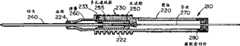
图9为图8所示导丝导入装置局部放大剖视图;Fig. 9 is a partially enlarged sectional view of the guide wire introducing device shown in Fig. 8;
图10为图8所示导丝导入装置侧视图,示出在退回位置上的针头;Figure 10 is a side view of the guide wire introduction device shown in Figure 8, showing the needle in the retracted position;
图11为用以将导丝导入病人、针头可退回的装置第二实施例侧视图;Fig. 11 is a side view of a second embodiment of a device for introducing a guide wire into a patient with a retractable needle;
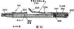
图12为图11所示导丝导入装置侧视图,示出在退回位置上的针头;Figure 12 is a side view of the guidewire introduction device shown in Figure 11, showing the needle in the retracted position;
图13为本发明针头可退回的导管插入装置侧视图;Fig. 13 is a side view of the catheter insertion device with retractable needle of the present invention;
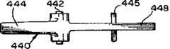
图14为图13所示导管插入装置底视图;Figure 14 is a bottom view of the catheter insertion device shown in Figure 13;
图15为图13所示导管插入装置剖面图;Fig. 15 is a sectional view of the catheter insertion device shown in Fig. 13;
图16为图13所示导管插入装置针头夹持器底视图;Fig. 16 is a bottom view of the needle holder of the catheter insertion device shown in Fig. 13;
图17为图16所示导管插入装置侧视图;Figure 17 is a side view of the catheter insertion device shown in Figure 16;
图18为本发明针头可退回的导管插入装置另一实施例部分剖示侧视图;Fig. 18 is a partially cutaway side view of another embodiment of the catheter insertion device with a retractable needle of the present invention;
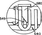
图19为图18所示导管插入装置局部放大图,示出在锁定位置上的锁定按钮;Fig. 19 is a partial enlarged view of the catheter insertion device shown in Fig. 18, showing the locking button in the locked position;
图20为图18所示导管插入装置部分剖示侧视图,示出在退回位置上的针头;Figure 20 is a side view, partially in section, of the catheterization device of Figure 18, showing the needle in the retracted position;
图21为图20所示导管插入装置局部放大图,示出在非锁定位置上的锁定按钮;Fig. 21 is a partial enlarged view of the catheter insertion device shown in Fig. 20, showing the locking button in the unlocked position;
图22为本发明针头可退回的导管插入装置第二替代性实施例剖面图;Fig. 22 is a cross-sectional view of a second alternative embodiment of a catheter insertion device with a retractable needle according to the present invention;
图23为图22所示导管插入装置剖面图,示出在退回位置上的针头;Figure 23 is a cross-sectional view of the catheterization device shown in Figure 22, showing the needle in the retracted position;
图24为图23所示导管插入装置局部放大剖面图;Fig. 24 is a partially enlarged cross-sectional view of the catheter insertion device shown in Fig. 23;
图25为图23所示导管插入装置局部放大剖面图。Fig. 25 is a partially enlarged cross-sectional view of the catheter insertion device shown in Fig. 23 .
优选实施例的详细描述Detailed description of the preferred embodiment
如图1~4、特别是图1所示,用以将套装在针头上的导管70插入病人的装置总的示为10。装置10具有一可退回的针头30,用以穿刺病人皮肤而插入导管70。在将导管70插入病人后,针头30自动退进装置10而使受污染的针头尖端套装在装置内以免意外的针头刺戳。As shown in FIGS. 1-4 , and in particular FIG. 1 , the device for inserting a needle-mounted
如图2~4所示,装置具有一大体上为筒形的壳体20、一针头30、一向后偏压针头的弹簧60和一对抗弹簧偏压可松开地夹持针头的针头夹持器40。针头可在一伸出位置和一退回位置两个位置之间操作。在伸出位置上,针头30向前从壳体20前端伸出。在退回位置上,针头退进壳体而将尖端套装在壳体内以免意外地碰触尖端。在针头如图2所示位于伸出位置时,弹簧将针头向后向退回位置上偏压。针头夹持器将针头可松开地夹持在伸出位置上。针头夹持器与导管70相互配合而在将导管从装置上取下时针头夹持器自动地松开针头而使针头退进壳体如图4所示。As shown in Figures 2-4, the device has a generally
现按图2对装置构件作更具体的说明。壳体大体上为筒形,壳体20的前端具有直径缩小的锥形端部22。将导管70装在端部22上。这样,端部22具有锥度以与导管70套筒72内部锥面配合。The components of the device will now be described in more detail according to FIG. 2 . The housing is generally cylindrical, with the front end of the
导管70具有大体上为锥形的套筒72和与导管套筒作固定连接的柔性套管74。导管70装在壳体端部22上而使套管74套装在针头前端上。但,针头尖端从套管中向前伸出而使尖端在使用前露出。
在将导管70装在端部22上时,导管套筒72与针头夹持器40接合。针头夹持器40为一与针头30作固定连接的长条形臂。此臂向前通过一开口伸出靠近端部的壳体前端。臂40的前部形成一随动器部分46。随动器部分通过靠近端部22的壳体开口从壳体向前伸出而与导管套筒72接合。
针头夹持器40具有一凸部45,凸部在随动器部分46的后面径向外凸。凸部45与前缘24接合,前缘由开口形成,臂40通过此开口在端部附近伸出。凸部45用作锁扣以便对抗弹簧偏压而卡住针头夹持器和所带针头。The
在将导管70装在端部22上时,导管套筒72卡紧针头夹持器40的随动器部分46而使凸部45卡在前缘24上。这样,在将导管装在装置上时使针头30对抗针头的偏压保持在伸出位置上。取下导管70会使针头夹持器径向向内偏移而使凸部脱离前缘。在本示例中,弹簧向后的偏压在取下导管时使针头夹持器径向偏移。When the
针头夹持器的臂是由柔性塑料构成的,因而此臂是可作弹性变形的。针头夹持器的臂40在其松弛状态下与前部开口的前缘24处于接触状态。前缘24最好向后倾斜而使在针头夹持器40上的凸部45形成一配接斜面。这两个配接面可在图3和4中最清楚地看出。弹簧所作向后的偏压力以一径向分力和一轴向分力的形式作用在此臂上。径向分力促使针头夹持器的臂40向内而使凸部45向上越过前缘24浮动直至与前缘脱离。弹簧60就将针头夹持器和所带针头向后推动而进入壳体,从而将针头尖端套装在壳体内。The arms of the needle holder are constructed of flexible plastic so that the arms are elastically deformable. The
装置10还具有在针头后端将其封住的流体储存器50。流体储存器50与针头30作流体连通而用作反流腔。因此,在将针头插入病人静脉时,血液就通过针头流入反流腔。反流腔50的后端是用多孔疏水通风栓52封住的。在血液进入反流腔时空气透过通风栓而使空气排出反流腔。但,通风栓52对血液是不可穿透的以免血液漏出反流腔。壳体和反流腔是由透明塑料构成的,因而在反流腔内的血液就用作针头已正确插入病人静脉的可视指示器。The
在本示例中,反流腔50和针头夹持器40整个地形成一单体结构。此两构件是用一种粘结剂如可用紫外线固化的环氧树脂进行固定连接的。弹簧围绕针头装在壳体内。弹簧前端支承在壳体前端,弹簧另一端支承在成整体的针头夹持器和反流腔上。In this example, the
在本示例中,壳体20短于针头30和反流腔50的组合长度。因此,壳体20后端一般是敞开的,使反流腔在退回针头时可向后伸出壳体如图4所示。装置还具有锁定或限制特性而使针头不会被向后推出壳体。最好在壳体侧面形成开口26,此开口在尺寸上可接纳针头夹持器臂40的前部46而起后向锁定的作用。针头夹持器的弹性径向向外偏压针头夹持器。在将针头向后推动时,针头夹持器46的前端嵌入开口26而使凸部46卡在开口的后沿上,使针头不致继续向后移动。此外,针头夹持器40的前端卡在开口26的前沿上而使针头不致向前移动,从而使针头退回后不会再伸出去。In this example,
在将导管70从装置上取下并插入病人时,来自病人的血液会流出导管后端。一般来说,一旦将导管接在流体储存器如静脉注射囊上,来自静脉注射囊内流体的流体压力足以防止或限制血液通过导管从病人流出。但,在将静脉注射囊接到导管上之前,血液会漏出导管。因此,在将导管插入病人之后就应堵住导管以免血液漏出。When
因此,端部22最好在将导管装在端部上时与导管套筒72内部构成流体密封。这样,在从壳体上取下导管和退回针头后,可将端部插入导管而堵住导管。此外,如图3所示,端部最好伸到针头夹持器40随动器部分46的前面而使端部22在退回针头后立即大体上堵住导管。此外,由于端部22在随动器部分46的前面伸出,针头在退回时和退回后都不会露出来。Thus,
如上所述形成的装置操作如下。在使用之前将针头30置于伸出位置上而使针头尖端露出。将针头尖端插入病人静脉。流入反流腔50的血液向医务人员指示针头已插入静脉。这时推进导管以便从装置10上取下导管而将导管70穿进病人静脉。为此,导管套筒72最好具有一凸体73以便医务人员可用握住装置的手的一个手指向前推动。在将导管推到针头夹持器40随动器部分46的前面时,针头夹持器40向内偏移而松开针头。弹簧60就向后推动针头30、针头夹持器40和反流腔50而使针头尖端套装在壳体20内。必要时医务人员就可将端部22插入导管以便重新堵住导管以免血液漏出。The device formed as described above operates as follows. Prior to use, the
图5~7示出另一优选实施例。在第二实施例中,对与图1~4所示和以上所述第一实施例构件相同的构件用相同的参考数字但加以100来表示。5-7 show another preferred embodiment. In the second embodiment, the same reference numerals are given to the same components as those of the first embodiment shown in FIGS. 1-4 and described above but with 100 added.
第二实施例总的示为110。装置110具有壳体120、可退回的针头130、向后偏压针头的弹簧160和对抗弹簧的偏压可松开地夹持针头的针头夹持器140。套装在针头上的导管170装在装置110的前端。针头夹持器140与导管配合以便在从装置110上取下导管时就松开针头,弹簧就将针头向后推进壳体120。A second embodiment is shown generally at 110 .
针头夹持器140的形状与结合第一实施例所述针头夹持器40相仿。针头夹持器具有与针头30作固定连接、弹性可挠曲的长条形臂。针头夹持器前端通过靠近端部122的壳体前端开口伸出。针头夹持器的前部146与导管套筒172的侧面接合。与第一实施例相仿,导管套筒172径向向外卡紧针头夹持器的臂而使臂的凸部145卡在由壳体前端开口形成的前缘124上。因此,在从装置110上取下导管170时,针头夹持器140向内偏移而松开针头130。弹簧就将针头向后推进壳体120。如图7所示,壳体经加长而使整个针头和反流腔在退回位置上套装在壳体内。The shape of the
这样,如同第一实施例,针头在使用后自动退回而使医务人员不必进行任何附加的步骤就可将受污染的针头安全地套装起来。将导管170插入病人这一步骤就足以使针头退回。但,如以下还要说明,医务人员必要时可推迟退回动作。In this way, as with the first embodiment, the needle is automatically retracted after use so that the medical personnel do not have to perform any additional steps to safely nest the contaminated needle. The step of inserting the
有时会要求医务人员在将导管插入病人后推迟退回动作。因此,装置110在壳体120侧面具有窗口121。将针头夹持器140置于窗口附近而使医务人员可用手夹紧针头夹持器。如果医务人员需控制退回动作,医务人员可施加压力以便径向向内偏移针头夹持器而使其接触一内壁125。这样,就把针头夹持器夹在医务人员握掌和内壁之间以免针头退进壳体。一旦医务人员松开针头夹持器,针头就退进壳体。Medical staff are sometimes asked to delay retracting the catheter after it has been inserted into the patient. Therefore, the
最好使窗口121的位置可使医务人员在握持装置110使用时能夹住针头夹持器。因此,握持部分是在壳体前端形成的。握持部分是沿壳体两侧一对彼此相对的凹弧面形成的。窗口121是在握持部分彼此相对的凹弧面中的一个表面上形成的。Preferably,
装置的操作如下。在使用前,针头向前从壳体伸出如图5所示。医务人员握住装置110壳体的握持部分。这时医务人员通过窗口121夹紧针头夹持器。将针头130插入病人作静脉注射。一旦在反流腔150内看到血液,就将导管轴向向前推进而将导管插入病人。一旦将导管轴向向前推到针头夹持器的前面,针头除非医务人员在针头夹持器上作力就会松脱退回。如果医务人员不需推迟退回动作,医务人员可松开手指作用在针头夹持器上的压力而使弹簧的偏压克服手指压力。医务人员也可用足够的力保持其胜过弹簧160偏压的握力。一旦医务人员松开装置,针头就自动退进壳体而将针头尖端套装起来。这样,针头在使用装置后不需任何附加的步骤如按压按钮就自动退回。与此同时,医务人员如需推迟退回动作而控制退回动作也不需作任何附加的步骤就可做到。通过使用装置时的自然步骤就能做到这种控制。但,即使医务人员要求推迟退回动作,只要医务人员对装置松握,针头还是会完全自动地退回去而不需任何其他的操作。The operation of the device is as follows. Before use, the needle protrudes forwardly from the housing as shown in FIG. 5 . The medical staff holds the grip portion of the
装置110还具有一可调的端部构件22。在第一实施例中,端部22与壳体成一整体。在第二实施例中,端部为一单个的构件,构件插在壳体前端的插座内,插座是为接纳端部构件作成的。端部构件122可相对于壳体120作轴向调整。通过调节端部构件的轴向位置可变动外露针头尖端伸出导管套管的长度。The
如图8~10特别是图8所示,用以将导丝270引入病人的装置总的示为210。装置具有用以穿入病人静脉的针头240。通过针头将导丝插入病人静脉。在将导丝插入病人后,插入针头自动退回而使经污染的针头不会接触使用装置的医务人员。此外,使用装置的医务人员必要时可控制装置的退回动作而推迟退回动作。但,即使推迟退回动作,一旦医务人员放下装置,退回动作就自动产生。As shown in FIGS. 8-10 and in particular FIG. 8 , the device for introducing a
如图8所示,装置具有壳体220,壳体具有直径缩小的端部224。针头240向前通过端部224开口伸出。壳体220的后端大体上是封闭的并具有一直径缩小的开口,导丝270通过此开口进入壳体内部。在壳体后端装一橡胶密封件280。导丝270通过密封件内一开口延伸而与密封件280构成流体密封。此外,密封件280与导丝作摩擦接合而使导丝与壳体220作摩擦连接。As shown in FIG. 8 , the device has a
在端部224后面,壳体具有由很多凸起的凸部形成的握持区222。在通常的操作中,使用人握住握持区以便在插入导丝时握住装置。Behind the end 224, the housing has a
弹簧260围着针头向后朝向退回位置偏压针头240。针头夹持器230可松开地将针头夹持在伸出位置上,在此位置上针头向前伸出壳体如图8所示。针头夹持器230具有长条形臂232,此臂通过枢销233与壳体220作绕轴转动的连接,枢销形成针头夹持器的活动枢轴线。锁扣235是在远离枢销233的臂端在臂232上成一整体地形成的。锁扣235伸进壳体内。Spring 260 biases needle 240 rearwardly around the needle toward the retracted position.
如图9所示,锁扣235卡在固定在针头240后端的反流腔250上。反流腔大体上为一筒形空腔。针头后端具有一侧口242以便在将针头插入病人静脉时血液通过侧口流入反流腔而向医务人员指示针头已穿入静脉。在推进导丝270前,导丝伸进针头240而使导丝前端位于针头内侧口242的后面。这样,导丝封住针头后端以免血液漏出反流腔后端。与此同时,导丝并不堵住侧口以便血液可通过针头流入反流腔。As shown in FIG. 9 , the lock 235 is locked on the
用一多孔通风栓封住反流腔250前端,通风栓可使空气透过,但不会使来自反流腔的血液通过。反流腔后端大体上是封闭的并具有一用以接纳导丝270的小孔。导丝通过后面的小孔穿入针头。这样,导丝封住反流腔后面的小孔以免血液漏出反流腔。The front end of the
如上所述,针头夹持器在一锁定位置和一非锁定位置之间绕轴转动,在锁定位置上针头夹持器对抗弹簧向后的偏压将针头夹持在伸出位置上,在非锁定位置上针头夹持器松开针头而使弹簧将针头向后推进壳体,从而将针头尖端套装起来。针头夹持器230在将导丝270插入病人后自动地从锁定位置绕轴转到非锁定位置上。导丝270阻止针头夹持器在将导丝插入病人之前绕轴转到非锁定位置上。As mentioned above, the needle holder pivots between a locked position in which the needle holder holds the needle in the extended position against the rearward bias of the spring, and an unlocked position. The needle retainer in the locked position releases the needle and allows the spring to push the needle back into the housing, thereby nesting the needle tip.
具体地说,通路236通过锁扣235延伸以便接纳导丝。导丝270通过锁扣通路236伸入反流腔如图10所示。在导丝留在锁扣通路内时锁扣不会绕轴转到非锁定位置上。在使导丝270后端移动到通路前面而将导丝从通路中脱出时,导丝不再阻止锁扣径向向外转动。弹簧260向后的偏压向后推动针头和所带反流腔。这一动作又径向向外推动锁扣,从而使臂232径向向外绕轴转离针头。弹簧就将针头推进壳体220如图10所示。Specifically, passageway 236 extends through latch 235 to receive a guidewire. The
如前所述,操作装置210的医务人员可随意进行干预以推迟退回动作。具体地说,如图8所示,在锁定位置上,针头夹持器230留在握持部分的狭槽内。这样,在医务人员握住握持部分222时,医务人员也就握住针头夹持器的壁232。只要医务人员握住针头夹持器,针头夹持器就不会绕轴转到非锁定位置上。这样,医务人员可在将导丝插入病人后推迟退回动作。但,只要医务人员松开针头夹持器230,针头夹持器就会绕轴转到非锁定位置上,弹簧就会将针头推到退回位置上。As previously mentioned, medical
这样所形成的装置操作如下。将针头240插入病人。流入反流腔的血液给出针头已插入静脉的可视指示。医务人员就通过针头推进导丝270而将导丝插入病人静脉。在推进导丝时,导丝穿过穿通锁扣235的通路236。一旦使导丝270送到锁扣的前面,针头夹持器就绕轴转到非锁定位置上,弹簧就将针头推进壳体220。如果医务人员需推迟退回动作,医务人员就在将导丝送到锁扣前面之前握住针头夹持器。在医务人员继续握住针头夹持器时,将导丝送到锁扣的前面。在医务人员需退回针头时,医务人员只需松开握住的针头夹持器。弹簧就自动地将针头向后推到退回位置上。The device thus formed operates as follows. The
如图11和12所示,用以将导丝370引入病人的第二实施例总的示为310。装置具有用以穿入病人静脉的针头340。通过针头将导丝370插入病人静脉。在将导丝插入病人后,插入针头就自动地退进壳体320而使受污染的针头不致接触到使用装置的医务人员。此外,使用装置的医务人员必要时可控制装置的退回动作而推迟退回动作。但,即使推迟退回动作,只要医务人员放下装置,退回动作就自动产生。As shown in FIGS. 11 and 12 , a second embodiment for introducing a guide wire 370 into a patient is shown generally at 310 . The device has a
导丝370最好为大体上不能拉伸的半柔性细丝。导丝前端是圆形的,导丝最好是硬质的。导丝的尺寸应使丝径稍小于针头340内孔以便导丝可在针头内滑动。Guidewire 370 is preferably a semi-flexible filament that is substantially instretchable. The front end of the guide wire is round, and the guide wire is preferably hard. The size of the guide wire should be such that the wire diameter is slightly smaller than the inner hole of the
装置具有空心壳体或筒体320。针头340通过一开口向前伸入壳体340前端。壳体320后端大体上是封闭的并具有直径缩小的开口,导丝370通过此开口进入壳体内部。橡胶密封件380位于壳体后部。导丝370通过密封件380内一开口延伸而与橡胶密封件构成液体密封。此外,密封件380与导丝作摩擦接合而使导丝与壳体320作摩擦连接。The device has a hollow housing or
弹簧360围着针头而向后向退回偏压针头340如图12所示。针头夹持器330可松开地将针头夹持在伸出位置上,在此位置上针头向前从壳体内伸出如图11所示。针头夹持器330为一与壳体成一整体的长条形臂而使臂330和壳体320形成一单一构件。臂330在成形时使臂径向向外向图12所示位置偏压。The
如图11所示,在使用之前臂330伸入壳体320内部。臂330的前端形成一锁扣335而使其与固定在针头340后端的反流腔350接合。反流腔350为一大体上成筒形的空心腔。针头后端具有一侧孔342以便在针头穿入病人静脉时血液通过测孔流入反流腔而向医务人员指示针头已穿入静脉。在推进导丝370之前导丝伸入针头340而使导丝前端位于针头侧孔342的后面。这样,导丝封住针头后端以免血液漏出反流腔后端。与此同时,导丝并不堵住侧孔而使血液可通过针头流入反流腔。As shown in FIG. 11, the
反流腔350的前端是用一多孔通风栓封住的,空气可从中透过,但来自反流腔的血液不能通过。反流腔后端大体上是封闭的,仅有用以接纳导丝370的小孔。导丝通过后面的小孔进入针头。这样,导丝封住反流腔后面的小孔以免血液漏出反流腔。The front end of the
如上所述,针头夹持器在一锁定位置和一非锁定位置之间绕轴转动,在锁定位置上针头夹持器对抗弹簧360向后的偏压将针头夹持在伸出位置上,在非锁定位置上针头夹持器松开针头而使弹簧可将针头向后推进壳体以便套住针头尖端。针头夹持器330在将导丝370穿入病人后自动地从锁定位置绕轴转到非锁定位置上。在将导丝穿入病人前导丝370防止针头夹持器绕轴转到非锁定位置上。As mentioned above, the needle holder pivots between a locked position in which the needle holder holds the needle in the extended position against the rearward bias of
具体地说,臂330具有用以接纳导丝370的一导丝前通路332和一导丝后通路334。通路332、334的位置和朝向应使通路332、334在臂330位于图11所示锁定位置时大体上与针头340同轴线。这样,导丝370与针头夹持器的臂330接合而可松开地将臂夹持在锁定位置上,因而对抗弹簧360的偏压将针头340可松开地夹持在伸出位置上。在导丝370留在锁定通路332、334中之一中时,此臂就被阻止绕轴转到非锁定位置上。在使导丝370后端向导丝前通路332的前面移动而使导丝从此通路中脱出时,导丝就不再能阻止此臂径向向外移动。弹簧360向后的偏压就向后推动针头340和所带反流腔350。这种情况连同臂330的径向偏压将此臂径向向外推动而使此臂径向向外绕轴转离针头。弹簧就将针头推入壳体320如图12所示。Specifically,
如图11所示,最好将臂330弯成槽形或凹形。槽形的顶面最好垂直向下脱离针头340的中心线或轴线。如图11所示,导丝370在导丝通路332、334之间的部分处在壳体322的外面而露出以便医务人员用手操作。这样,医务人员可同时握住装置并将导丝370用手送入病人。具体地说,医务人员在用一手握住装置310时可接触通路332、334之间的导丝外露部分并向前移动导丝以便将导丝通过针头340穿入病人。As shown in FIG. 11, the
图13~17特别是图13示出用以将导管450插入病人的导管插入装置410。装置410具有用以将导管450导入病人的针头420。插入装置410在操作人员从装置上取下导管450时可使针头420自动退入插入装置410。此外,装置的构形使操作人可推迟退回动作。这些特征使操作人可控制退回动作而使针头在使用后自动退回,从而使针头成为不可重复使用而可安全处理的针头。13-17, particularly FIG. 13, illustrate a
导管插入装置410具有大体上为筒形的空心筒体或壳体430,壳体具有直径缩小的前方端部434。使针头420可松开的夹持而使针头的前端通过筒体端部434内一开口向前伸出。针头可在一伸出位置和一退回位置之前操作。在退回位置上将针头套装在壳体内。
先将导管450装在导管插入装置410的前端而使针头420通过导管从装置前面伸出。导管450具有套管452和套筒454。套管452套住或接纳针头420的前部而使针头尖端稍从套管开口端伸出。Firstly, the
导管450具有装在导管套筒454上的柔性长条形套管452。套管452与针头作伸缩式接合而使套管套住针头并使针头尖端422伸出套管前端。尖端422的后沿称作针头斜面的跟部。在针头斜面跟部和套管前端之间的长度称作定位长度。定位长度最好是可调的。
在本示例中,定位长度是可调的,只有保持针头伸出的位置不变而在将导管在使用前装在筒体上时调节导管450的位置。筒体430端部是可调的以便调节导管。In this example, the positioning length is adjustable, only by maintaining the position where the needle is extended and adjusting the position of the
筒体430具有可更换的端部434如图15所示。在本示例中,端部434为一单独的构件,将此构件插在筒体430前端的开口内。端部434具有外部环形凸缘439,导管套筒454的后沿455靠在此凸缘上。因此,改变端部434的轴向位置就可调节凸缘439的轴向位置,从而调节定位长度。The
端部434具有大体上为筒形的后部,此后部具有略小于筒体430前部内径的外径。若干齿体438从端部434后端外表面伸出。齿体438与筒体430内表面接合而使端部434与筒体连接。凸缘439的轴向位置取决于端部后端插入筒体430的长度。调节端部插入长度就可调节凸缘439的轴向位置,从而调节定位长度。
如图15所示,大体上为筒形的腔470装在针头的后端。腔470形成一反流腔。将反流腔470装在针头420后端而使反流腔围住针头420的后端。反流腔后端用一多孔通风栓472封住。通风栓472使空气排出腔470而阻止血液逸出反流腔470。As shown in Figure 15, a generally
偏压件460将针头420向后向其退回位置偏压。在本示列中,偏压件为一围在针头外面的螺旋弹簧460。弹簧460前端支承在在端部434内形成的凸肩上。弹簧的后端支承在反流腔470上而向后偏压反流腔和所带针头。也可使弹簧460通过一种粘结剂如环氧树脂与针头连接。一与壳体430作绕轴转动连接的针头夹持器或杆臂440对抗弹簧460的偏压对针头420和反流腔470作可松开的夹持。
针头夹持器440具有前部444和后部448。在本示例中,前部444从枢轴442向前延伸,后部448从枢轴442向后延伸。夹持器440前部444内表面在将导管装在插入装置410上时与导管450的套筒454接触。夹持器440的前部444最好与导管套筒454的外表面接触或接合。也可使前部与导管套筒454内表面接合。针头夹持器440的后部448在将导管装在插入装置上时位于枢点和导管450的后面。
针头夹持器440的后部448具有一带锁扣446的释放杆。此杆可在一锁定位置和一非锁定位置之间绕轴转动。在锁定位置上释放杆作大体上平行于装置410纵轴线的延伸。在释放杆端部的锁扣446穿过筒体430侧边的开口432而使反流腔470后端与锁扣接触以便将针头夹持在其伸出位置上。The
应找正针头420的尖端422而使尖端的斜面相对于筒体430作圆周上的定位如图13所示。具体地说,最好使尖端作圆周上的定位而使尖端最靠前的一点垂直地位于尖端斜面跟部的下面。在本示例中,反流腔470在构形上与针头夹持器配合以便找正针头斜面如以下所述。The
反流腔470大体上为筒形而具有一沿反流腔长度延伸的平面。针头斜面所要求的圆周上的朝向是在使反流腔与针头连接时相对于反流腔的平面进行定位的。如图15所示,针头夹持器后部448具有大体上为平面的表面或凸台449,此表面与反流腔470配合以便相对于筒体430在圆周上找正针头420。如图15所示,在针头夹持器440处于锁定位置时,使反流腔470的平面与针头夹持器凸台449找正并接合。这样,就使反流腔470和所带针头420相对于针头夹持器、因而也相对于筒体430在圆周上进行了定位。The
在将导管装在插入装置上时在针头夹持器杆件的前部444和导管套筒454之间的接合阻止杆件绕轴转到其非锁定位置上。最好使夹持器440后部448受偏压而绕轴转离壳体430侧面。在本示例中,与反流腔470接合的锁扣446平面是带有角度的,从而使弹簧460的部分向后的偏压传递到杆件上而径向向外偏压杆件。在经过杆件端部取下导管450后,夹持器自由地绕轴转到其非锁定位置上,因而使锁扣446脱离针头420后端。弹簧460就将针头向后推进壳体430。Engagement between the
必要时操作人可按需要控制针头的退回动作如下。针头夹持器440具有一肋条445,此肋条相对于针头夹持器杆件纵轴线是横向布置的。如图13和14所示,筒件430具有由若干平行间隔的肋条431构成的握持部分。针头夹持器肋条445大体上平行于握持肋条431而使针头夹持器肋条445构成握持部分的一部分。这样,如操作人需控制针头的退回动作,操作人就在握住装置410的握持部分时握紧针头夹持器的肋条445。When necessary, the operator can control the retraction action of the needle as required. The
操作人通过握紧针头夹持器肋条445阻止针头夹持器440从锁定位置绕轴转到非锁定位置上。在操作人将导管450插入病人后,针头夹持器前部444与导管脱开,因而使针头夹持器可绕轴转向非锁定位置。但,操作人握紧针头夹持器肋条445就阻止针头夹持器绕轴转到非锁定位置上。操作人在针头夹持器肋条445上在需退回针头前保持一向内的力就可控制退回动作。在使导管450脱开针头夹持器440后一旦操作人松开针头夹持器肋条445,针头夹持器就自由地绕轴转到非锁定位置上而使弹簧460将针头420向后推进筒体430。这样,装置在使导管450脱开插入装置壳体之前一直阻止发生退回动作。此外,装置可使操作人控制退回动作的时间而使退回动作发生在使用装置之后。The operator prevents the
导管插入装置先是处在图13所示状态。导管插入装置410的操作人首先用针头422穿刺病人血管。在针头422穿入病人血管时,血液通过针头420流动而聚集在透明的反流腔470内。血液在反流腔470内的出现可用以向操作人指示针头已正确地穿入血管,导管450也已处于正确的位置。操作人就使导管套筒454向针头420的尖端422滑离装置410前端以便将导管管腔452插入病人血管。从装置上取下导管套筒454的动作在导管套筒边缘455通过杆件444端部时使夹持器440自动地绕轴转动而与针头端部脱离接触。但,操作人通过在取下导管套筒前握紧针头夹持器肋条445暂时制止自动退回动作。一旦操作人松开针头夹持器肋条445,针头夹持器绕轴转动而脱开针头420。针头就松脱而在弹簧460的偏压下退入导管插入装置410的筒体430。操作人除了需作出正常的插入导管步骤外不必进行其他的动作来使针头退回。与此同时,操作人必要时可作出干预而推迟退回动作。The catheter insertion device is first in the state shown in FIG. 13 . The operator of
如图15所示,端部434还具有一个内径稍大于针头420外径的收缩部分435。收缩部分435和针头之间的紧配合在重新堵塞步骤中限制血液漏进筒体430如以下进一步的说明所示。此外,外圆肋437从端部434前端径向凸出。肋437与导管套筒454的内腔配合而形成流体密封。此内腔具有斜度,其较大直径大于端部434上肋437的直径。内腔最前部分最好形成大体上为筒形的零斜度区。零斜度区的内径与端部434上肋437的直径相似。这样,在将导管450装上筒体430时肋437与零斜度区接合而形成流体密封。As shown in FIG. 15 , the
在将导管插入病人和使针头420退回后可将装置端部434插入导管450而重新堵塞导管以免血液漏出导管。为此,导管450和(或)针头夹持器440前端在构形上便于绕轴转动针头夹持器而使针头夹持器前端并不影响重新堵塞导管。具体地说,针头夹持器前缘是圆形的以便针头夹持器440前部444在针头夹持器与导管450边缘455接触时绕轴向下转动如图13和15透视图所示。边缘455也可以是圆形的或斜形的以便在将导管从装置上卸下足够程度而使针头夹持器脱离针头420后,针头夹持器440在端部434相对于导管450向前轴向移动时绕轴转动。After the catheter has been inserted into the patient and the
在针头退回后将筒体430端部434插入导管空腔而重新堵住导管450,从而使圆形肋437与零斜度区接合。肋437和零斜度区配合而形成流体密封,从而使血液不会围绕端部434从导管内漏出。此外,退回的针头420与端部434收缩部分435形成密封而减少或避免血液从导管450漏进筒体430。在退回位置上,锁扣446使针头弯曲和(或)弯形。Inserting the
端部434还具有一外周边凹部436。最初,导管450围住端部434而操作人不能看到凹部436。当操作人从端部434上卸下导管450时,凹部436显出而操作人可看到凹部。在凹部436显出后,继续卸下导管450就将导管移出针头夹持器440的前端而使针头夹持器绕轴转到非锁定位置上。这样,凹部对操作人成为可视指示器而给出可视信号,表明继续向前移动导管会使针头退回。凹部436最好在构形上加大在凹部和端部外表面其余部分之间的区别。也可采用一种不同的可视指示如在端部434上针头夹持器440前端的轴向后面采用一种环形着色线条。The
图18~20示出导管插入装置的另一实施例510。图17~20所述另一实施例具有与结合图13~17所述第一实施例的构件相仿的构件。对图18~20中与图13~17中构件相仿的构件采用相同的标号但加以500。18-20 illustrate another
导管插入装置510具有从筒体或壳体530向前伸出的插入针头520。针头520用带有释放杆的针头夹持器540夹持。针头夹持器540与装在壳体530端部534上的导管550接合。这样,在将导管装在装置510壳体530上时导管550阻止针头夹持器540绕轴转动而防止针头520退回。
如在以上结合图13~17所述实施例中,在图18中导管插入装置510在操作上也不用手动干预或不需单独的退回步骤就使针头自动退回。针头夹持器540向非锁定位置受有偏压而在将导管550从插入装置510上取下时针头夹持器540自动绕轴转到其非锁定位置上而松开针头520。弹簧560就将针头520向后推进壳体530而将针头520尖端安全地套装在壳体内。As in the embodiment described above in connection with FIGS. 13-17 , in FIG. 18 the
此外,如在前一实施例中,装置510具有外露手动操作的表面供操作人必要时干预而推迟退回动作。具体地说,装置具有与一卡爪549接合的控制按钮580,卡爪与针头夹持器540连接。控制按钮580在一锁定位置和一非锁定位置之间操作。在锁定位置上控制按钮与针头夹持器540上的卡爪549接合以免针头夹持器绕轴转到非锁定位置上而松开针头520。控制按钮可向非锁定位置移动,也就是使针头夹持器540处于非锁定位置。Furthermore, as in the previous embodiment, the
控制按钮580和卡爪549具有配合斜面。在针头夹持器540绕轴转动时卡爪和控制按钮的配合斜面将一垂直的力传递给按钮而使控制按钮向上移到非锁定位置上。因此,不用操作人的干预,在将导管550从壳体530上取下时,针头夹持器540绕轴转到非锁定位置上而使控制按钮移到非锁定位置上。针头就退进壳体。The
操作人可在取下导管前按下控制按钮580进行干预而推迟退回动作。由操作人在控制按钮上施加向下的力可使卡爪549锁定就位而防止针头夹持器绕轴转动。在将导管从壳体上取下后,只要操作人按住控制按钮,针头夹持器就夹持针头。只要操作人松开控制按钮,卡爪就自由地转动而使针头夹持器绕轴转到非锁定位置上,针头就退回。这样,在使用装置之后,插入针头就自动退回,但必要时操作人可推迟退回动作。The operator may intervene by pressing the
装置510还示出另一种对反流腔520的安排。反流腔520可如前一实施例在构形上使反流腔470封住针头420后面的开口端并使针头夹持器440与反流腔接合。在本示例中,也可使针头520的后端从反流腔570向后伸出而使针头夹持器540与针头后端接合。将针头后端堵住以免血液漏进壳体。此外,在针头侧面形成一侧孔,反流腔围住侧孔。来自病人的血液通过侧孔流进反流腔而用作病人动脉已被穿刺的可视指示器。
图22~25示出导管插入装置另一实施例610。装置610装有前面所述相似的构件。对这些构件用相同的标号但加以600。22-25 illustrate another
导管插入装置610具有从筒体或壳体630向前伸出的插入针头620。针头620是用带有释放杆、可绕轴转动的针头夹持器640作可松开的夹持的。针头夹持器640的一端与装在壳体630端部634上的导管650接合。在这种安排下,导管650在将其装在壳体630上、夹持器之下时阻止针头夹持器640松开针头620。
如在以上结合图13~21所述实施例中,图22所示导管插入装置610也可不用手动干预或不需单独的退回步骤进行操作而自动退回针头。针头夹持器640受有朝向非锁定位置的偏压,从而在将导管650从插入装置610上取下时针头夹持器640就自动绕轴转到其非锁定位置上而松开针头620。弹簧660就将针头620向后推进壳体630而将针头620尖端安全地套装在壳体内。As in the embodiments described above in connection with FIGS. 13-21 , the
此外,如在前述实施例中,装置610具有外露手动操作的表面以便操作人必要时进行干预而推迟退回动作。具体地说,壳体具有向操作人提供握持装置610所需表面的握持部分691。针头夹持器640位于握持部分631附近以便操作人可方便地接触针头夹持器以免针头夹持器绕轴转到非锁定位置上。In addition, as in the previous embodiments, the
如图22和23所示,壳体630具有握持部分631,这是由若干平行间隔的肋条构成的。肋条形成凸弧形安全防滑表面。如图13所示,壳体可具有用以握住装置的对置握持表面。在本示例中,筒体具有在壳体一侧的握持部分631,而针头夹持器640的后部648位于壳体与握持部分相对的另一侧。针头夹持器640后部648的外露表面在构形上与握持部分631相似。因此,在操作人握住装置使用时,操作人在装置上所加垂直的握力压下针头夹持器的后部。只要操作人压下针头夹持器的后部,操作人就阻止针头夹持器绕轴径向向外转动而松开针头使其退回。As shown in Figures 22 and 23, the
装置610还具有伸缩式筒体以缩短使用前壳体的总长。装置610也可采用如以上在装置410-510中所述单件式壳体。The
装置610的壳体630具有两个构件,一外套筒690和一内套筒695。内套筒695在外套筒690内伸缩。在使用前,将内套筒695套装在外套筒690后端内。在使针头620退回时,反流腔670和所带针头接触内套筒而使内套筒在针头退回时向后移动。这样,外套筒套装在外面而延长壳体的长度以适应针头的长度。
壳体具有一前止动体,用以防止内套筒695被重新插入外套筒690。壳体还具有一后止动体,用以防止内套筒被向后移出外套筒后缘。The housing has a front stop to prevent the
一对位于内套筒695侧面的弹性锁片697与外套筒690的后缘配合而用作前止动体。锁片697受径向向外的偏压。在将内套筒695套装在外套筒690内时,锁片697与外套筒内表面接合而使锁片大体上与内套筒的外表面对齐。在将内套筒向后移动而使锁片位于外套筒后部时,锁片径向向外弯曲如图23和24所示。因此,试图在退回后向前移动内套筒会使锁片与外套筒后缘相接,因而阻止向前的移动。A pair of elastic locking pieces 697 located on the side of the
在外套筒690上的环形缘部693与内套筒695上的环形凸缘696配合而用作后止动体。如图23和24所示,环形缘部693从外套筒690的后缘径向向外凸起。环形凸缘696从内套筒695前缘径向向外凸起。在将内套筒向后移动时,环形凸缘696与环形缘部693接合而阻止内套筒进一步向后移动。An annular rim 693 on the
以上所述仅供说明而非供限定之用。这里并不排除所示和所述特征或其某些部分的任何等效内容。但,应该承认,在由所附权利要求书所限定的本发明范围和精神以内可以作出各种修改。The foregoing is for illustration only and not for limitation. This does not exclude any equivalents to the features shown and described or parts thereof. It should be recognized, however, that various modifications may be made within the scope and spirit of the invention as defined by the appended claims.
Claims (22)
Applications Claiming Priority (6)
| Application Number | Priority Date | Filing Date | Title |
|---|---|---|---|
| US9480198P | 1998-07-31 | 1998-07-31 | |
| US11250498P | 1998-12-14 | 1998-12-14 | |
| US12088899P | 1999-02-20 | 1999-02-20 | |
| US60/094,801 | 1999-02-20 | ||
| US60/112,504 | 1999-02-20 | ||
| US60/120,888 | 1999-02-20 |
Publications (1)
| Publication Number | Publication Date |
|---|---|
| CN1319023Atrue CN1319023A (en) | 2001-10-24 |
Family
ID=27377796
Family Applications (1)
| Application Number | Title | Priority Date | Filing Date |
|---|---|---|---|
| CN99811219.4APendingCN1319023A (en) | 1998-07-31 | 1999-05-13 | Retractable needle medical device |
Country Status (14)
| Country | Link |
|---|---|
| EP (1) | EP1100562B1 (en) |
| JP (1) | JP3796514B2 (en) |
| CN (1) | CN1319023A (en) |
| AT (1) | ATE251476T1 (en) |
| AU (1) | AU4077999A (en) |
| BR (1) | BR9912660A (en) |
| CA (1) | CA2338255A1 (en) |
| DE (1) | DE69911976T2 (en) |
| DK (1) | DK1100562T3 (en) |
| ES (1) | ES2209439T3 (en) |
| MX (1) | MXPA01001158A (en) |
| PL (1) | PL345957A1 (en) |
| PT (1) | PT1100562E (en) |
| WO (1) | WO2000006221A1 (en) |
Cited By (25)
| Publication number | Priority date | Publication date | Assignee | Title |
|---|---|---|---|---|
| CN103596616A (en)* | 2011-01-31 | 2014-02-19 | 血管途径公司 | Intravenous catheter and insertion device with reduced blood spatter |
| WO2014063353A1 (en)* | 2012-10-26 | 2014-05-01 | Zhang Jianming | Puncture needle tube component of indwelling needle with needle tip protective sleeve |
| CN105007966A (en)* | 2012-11-09 | 2015-10-28 | 康尔福盛303公司 | Conduit Assemblies for Closed Systems |
| CN105169545A (en)* | 2010-06-25 | 2015-12-23 | 史密斯医疗Asd公司 | Catheter Assembly With Seal Member |
| US9522254B2 (en) | 2013-01-30 | 2016-12-20 | Vascular Pathways, Inc. | Systems and methods for venipuncture and catheter placement |
| US9675784B2 (en) | 2007-04-18 | 2017-06-13 | Vascular Pathways, Inc. | Intravenous catheter insertion and blood sample devices and method of use |
| US9861792B2 (en) | 2011-02-25 | 2018-01-09 | C. R. Bard, Inc. | Medical component insertion device including a retractable needle |
| US9872971B2 (en) | 2010-05-14 | 2018-01-23 | C. R. Bard, Inc. | Guidewire extension system for a catheter placement device |
| US9950139B2 (en) | 2010-05-14 | 2018-04-24 | C. R. Bard, Inc. | Catheter placement device including guidewire and catheter control elements |
| CN108939204A (en)* | 2017-04-27 | 2018-12-07 | 王祖扬 | A kind of syringe needle manual retrieving formula intravenous infusion needle |
| US10220191B2 (en) | 2005-07-06 | 2019-03-05 | Vascular Pathways, Inc. | Intravenous catheter insertion device and method of use |
| US10232146B2 (en) | 2014-09-05 | 2019-03-19 | C. R. Bard, Inc. | Catheter insertion device including retractable needle |
| US10384039B2 (en) | 2010-05-14 | 2019-08-20 | C. R. Bard, Inc. | Catheter insertion device including top-mounted advancement components |
| US10426931B2 (en) | 2010-05-14 | 2019-10-01 | C. R. Bard, Inc. | Catheter placement device and method |
| US10493262B2 (en) | 2016-09-12 | 2019-12-03 | C. R. Bard, Inc. | Blood control for a catheter insertion device |
| USD903101S1 (en) | 2011-05-13 | 2020-11-24 | C. R. Bard, Inc. | Catheter |
| USD903100S1 (en) | 2015-05-01 | 2020-11-24 | C. R. Bard, Inc. | Catheter placement device |
| USD921884S1 (en) | 2018-07-27 | 2021-06-08 | Bard Access Systems, Inc. | Catheter insertion device |
| US11040176B2 (en) | 2015-05-15 | 2021-06-22 | C. R. Bard, Inc. | Catheter placement device including an extensible needle safety component |
| CN114642784A (en)* | 2020-12-21 | 2022-06-21 | 巴德阿克塞斯系统股份有限公司 | Catheterization Systems and Catheter Placement Systems |
| US11389626B2 (en) | 2018-03-07 | 2022-07-19 | Bard Access Systems, Inc. | Guidewire advancement and blood flashback systems for a medical device insertion system |
| US11400260B2 (en) | 2017-03-01 | 2022-08-02 | C. R. Bard, Inc. | Catheter insertion device |
| US11559665B2 (en) | 2019-08-19 | 2023-01-24 | Becton, Dickinson And Company | Midline catheter placement device |
| US11925779B2 (en) | 2010-05-14 | 2024-03-12 | C. R. Bard, Inc. | Catheter insertion device including top-mounted advancement components |
| US12440652B2 (en) | 2019-09-20 | 2025-10-14 | Bard Peripheral Vascular, Inc. | Intravenous catheter-placement device and method thereof |
Families Citing this family (32)
| Publication number | Priority date | Publication date | Assignee | Title |
|---|---|---|---|---|
| US6641564B1 (en)* | 2000-11-06 | 2003-11-04 | Medamicus, Inc. | Safety introducer apparatus and method therefor |
| US7001396B2 (en) | 2003-03-26 | 2006-02-21 | Enpath Medical, Inc. | Safety introducer assembly and method |
| JP2004538103A (en) | 2001-08-09 | 2004-12-24 | ベクトン・ディキンソン・アンド・カンパニー | Retractable safety needle device |
| US6730062B2 (en) | 2001-10-11 | 2004-05-04 | Medex, Inc. | Safety catheter with non-removable retractable needle |
| US7258678B2 (en) | 2002-03-14 | 2007-08-21 | Becton, Dickinson And Company | Retractable safety needle |
| CN101203253A (en)* | 2005-05-11 | 2008-06-18 | 医疗器械创新有限公司 | A syringe with removable needle |
| US7753877B2 (en) | 2005-08-08 | 2010-07-13 | Smiths Medical Asd, Inc. | Needle guard strut wall clip |
| US7632243B2 (en)* | 2005-08-08 | 2009-12-15 | Smiths Medical Asd, Inc. | Duckbill catheter release mechanism |
| US7650192B2 (en) | 2005-12-02 | 2010-01-19 | Medtronic, Inc. | Passive charge of implantable medical device utilizing external power source and method |
| CA2875284C (en)* | 2006-09-29 | 2016-05-31 | Tyco Healthcare Group Lp | Flashback chamber visual enhancement |
| DE102007049446A1 (en) | 2007-10-16 | 2009-04-23 | Cequr Aps | Catheter introducer |
| US8216188B2 (en)* | 2009-06-29 | 2012-07-10 | Don Millerd | Safety catheter |
| US9526846B2 (en) | 2009-08-19 | 2016-12-27 | Safety Syringes, Inc. | Patient-contact activated needle stick safety device |
| WO2012015415A1 (en) | 2010-07-29 | 2012-02-02 | Becton, Dickinson And Company | Passively shielding needle assembly with skin sensor |
| MX366712B (en)* | 2012-07-04 | 2019-07-19 | Equipos Medicos Vizcarra S A Star | Extraction device for collecting blood samples, including a catheter and a safety system. |
| US11224724B2 (en)* | 2013-03-12 | 2022-01-18 | Teleflex Medical Incorporated | Catheter insertion device |
| DE102013224431B4 (en) | 2013-11-28 | 2015-06-18 | 4A Engineering Gmbh | Setting aid for setting a catheter for diabetics |
| US9555221B2 (en) | 2014-04-10 | 2017-01-31 | Smiths Medical Asd, Inc. | Constant force hold tip protector for a safety catheter |
| JP6096229B2 (en)* | 2015-01-20 | 2017-03-15 | ベクトン・ディキンソン・アンド・カンパニーBecton, Dickinson And Company | How the needle assembly operates |
| ES2975734T3 (en) | 2015-01-29 | 2024-07-12 | Becton Dickinson Co | Integrated Quick Insert Catheter |
| WO2016152415A1 (en)* | 2015-03-25 | 2016-09-29 | テルモ株式会社 | Catheter assembly |
| AU2018234838B2 (en)* | 2017-03-17 | 2023-02-02 | Becton, Dickinson And Company | Midline catheter placement device |
| BR112022005254A2 (en) | 2019-09-24 | 2022-06-14 | Bard Access Systems Inc | Acute central venous catheter and peripherally inserted venous catheter integrated |
| CA3168492A1 (en) | 2020-01-23 | 2021-07-29 | Bard Access Systems, Inc. | Splitable catheter docking station system |
| EP4135819A1 (en) | 2020-04-23 | 2023-02-22 | Bard Access Systems, Inc. | Rapidly insertable central catheters including catheter assemblies |
| WO2021236950A1 (en) | 2020-05-21 | 2021-11-25 | Bard Access Systems, Inc. | Rapidly insertable central catheters including catheter assemblies |
| AU2021303150B2 (en) | 2020-06-29 | 2025-10-02 | Bard Access Systems, Inc. | Rapidly insertable central catheters including catheter assemblies and methods thereof |
| CA3186461A1 (en) | 2020-06-29 | 2022-01-06 | Bard Access Systems, Inc. | Rapidly insertable central catheters including assemblies |
| AU2021371314B2 (en) | 2020-10-28 | 2025-09-25 | Bard Access Systems, Inc. | Catheter placement system with stiffening system |
| AU2021400331B2 (en) | 2020-12-17 | 2025-09-25 | Bard Access Systems, Inc. | Rapidly insertable central catheters and assemblies |
| EP4259254A1 (en) | 2020-12-21 | 2023-10-18 | Bard Access Systems, Inc. | Optimized structural support in catheter insertion systems |
| WO2025052971A1 (en)* | 2023-09-07 | 2025-03-13 | テルモ株式会社 | Catheter assembly |
Family Cites Families (16)
| Publication number | Priority date | Publication date | Assignee | Title |
|---|---|---|---|---|
| US4026287A (en) | 1975-12-10 | 1977-05-31 | Irene Haller | Syringe with retractable cannula |
| US4592744A (en) | 1985-08-14 | 1986-06-03 | The University Of Virginia Alumni Patents Foundation | Self-resheathing needle assembly |
| US4900307A (en) | 1987-04-29 | 1990-02-13 | Kulli John C | Safety retracting needle for use with syringe |
| US4747831A (en) | 1987-04-29 | 1988-05-31 | Phase Medical, Inc. | Cannula insertion set with safety retracting needle |
| US4813426A (en) | 1987-11-09 | 1989-03-21 | Habley Medical Technology Corporation | Shielded safety syringe having a retractable needle |
| US4892107A (en) | 1988-01-05 | 1990-01-09 | Habley Medical Technology Corp. | Single use, safety blood collection device |
| US4808169A (en) | 1988-01-14 | 1989-02-28 | Habley Medical Technology Corporation | Disposable safety syringe having means for retracting its needle cannula into its medication cartridge |
| US5125414A (en) | 1990-01-16 | 1992-06-30 | Dysarz Edward D | Trap in barrel one handed retracted blood sampling device |
| US5697907A (en)* | 1993-07-20 | 1997-12-16 | Graphic Controls Corporation | Safety catheter |
| US5376075A (en)* | 1993-08-31 | 1994-12-27 | Haughton; Victor M. | Catheter sharp retraction system |
| CA2135706C (en)* | 1993-11-15 | 1999-06-15 | Walter E. Cover | Retractable-needle cannula insertion set with refinements to better control leakage, retraction speed, and reuse |
| US5579780A (en)* | 1994-10-11 | 1996-12-03 | Zadini; Filiberto P. | Manual guidewire placement device |
| US5795339A (en)* | 1995-03-07 | 1998-08-18 | Becton Dickinson And Company | Catheter-advancement actuated needle retraction system |
| EP0763369B1 (en)* | 1995-09-18 | 2002-01-09 | Becton, Dickinson and Company | Needle shield with collapsible cover |
| US5704914A (en)* | 1996-02-23 | 1998-01-06 | Stocking; John E. | Catheter placement assembly |
| US5685855A (en)* | 1996-07-23 | 1997-11-11 | Erskine; Timothy J. | Protected needle catheter placement device with sampling provisions and method for its use |
- 1999
- 1999-05-13CNCN99811219.4Apatent/CN1319023A/enactivePending
- 1999-05-13DEDE69911976Tpatent/DE69911976T2/ennot_activeExpired - Lifetime
- 1999-05-13ESES99924227Tpatent/ES2209439T3/ennot_activeExpired - Lifetime
- 1999-05-13CACA002338255Apatent/CA2338255A1/ennot_activeAbandoned
- 1999-05-13EPEP99924227Apatent/EP1100562B1/ennot_activeExpired - Lifetime
- 1999-05-13DKDK99924227Tpatent/DK1100562T3/enactive
- 1999-05-13AUAU40779/99Apatent/AU4077999A/ennot_activeAbandoned
- 1999-05-13MXMXPA01001158Apatent/MXPA01001158A/enactiveIP Right Grant
- 1999-05-13PTPT99924227Tpatent/PT1100562E/enunknown
- 1999-05-13BRBR9912660-5Apatent/BR9912660A/ennot_activeIP Right Cessation
- 1999-05-13JPJP2000562071Apatent/JP3796514B2/ennot_activeExpired - Lifetime
- 1999-05-13WOPCT/US1999/010609patent/WO2000006221A1/enactiveIP Right Grant
- 1999-05-13ATAT99924227Tpatent/ATE251476T1/ennot_activeIP Right Cessation
- 1999-05-13PLPL99345957Apatent/PL345957A1/enunknown
Cited By (68)
| Publication number | Priority date | Publication date | Assignee | Title |
|---|---|---|---|---|
| US11020571B2 (en) | 2005-07-06 | 2021-06-01 | Vascular Pathways, Inc. | Intravenous catheter insertion device and method of use |
| US10912930B2 (en) | 2005-07-06 | 2021-02-09 | Vascular Pathways, Inc. | Intravenous catheter insertion device and method of use |
| US12370349B2 (en) | 2005-07-06 | 2025-07-29 | Vascular Pathways, Inc. | Intravenous catheter insertion device and method of use |
| US11577054B2 (en) | 2005-07-06 | 2023-02-14 | Vascular Pathways, Inc. | Intravenous catheter insertion device and method of use |
| US10806906B2 (en) | 2005-07-06 | 2020-10-20 | Vascular Pathways, Inc. | Intravenous catheter insertion device and method of use |
| US10220191B2 (en) | 2005-07-06 | 2019-03-05 | Vascular Pathways, Inc. | Intravenous catheter insertion device and method of use |
| US11925778B2 (en) | 2005-07-06 | 2024-03-12 | Vascular Pathways, Inc. | Intravenous catheter insertion device |
| US9675784B2 (en) | 2007-04-18 | 2017-06-13 | Vascular Pathways, Inc. | Intravenous catheter insertion and blood sample devices and method of use |
| US9757540B2 (en) | 2007-04-18 | 2017-09-12 | Vascular Pathways, Inc. | Intravenous catheter insertion and blood sample devices and method of use |
| US10086171B2 (en) | 2007-05-07 | 2018-10-02 | Vascular Pathways, Inc. | Intravenous catheter insertion and blood sample devices and method of use |
| US10799680B2 (en) | 2007-05-07 | 2020-10-13 | Vascular Pathways, Inc. | Intravenous catheter insertion and blood sample devices and method of use |
| US10525236B2 (en) | 2007-05-07 | 2020-01-07 | Vascular Pathways, Inc. | Intravenous catheter insertion and blood sample devices and method of use |
| US11925779B2 (en) | 2010-05-14 | 2024-03-12 | C. R. Bard, Inc. | Catheter insertion device including top-mounted advancement components |
| US10426931B2 (en) | 2010-05-14 | 2019-10-01 | C. R. Bard, Inc. | Catheter placement device and method |
| US12296115B2 (en) | 2010-05-14 | 2025-05-13 | C. R. Bard, Inc. | Insertion device |
| US9950139B2 (en) | 2010-05-14 | 2018-04-24 | C. R. Bard, Inc. | Catheter placement device including guidewire and catheter control elements |
| US11135406B2 (en) | 2010-05-14 | 2021-10-05 | C. R. Bard, Inc. | Catheter insertion device including top-mounted advancement components |
| US9872971B2 (en) | 2010-05-14 | 2018-01-23 | C. R. Bard, Inc. | Guidewire extension system for a catheter placement device |
| US10722685B2 (en) | 2010-05-14 | 2020-07-28 | C. R. Bard, Inc. | Catheter placement device including guidewire and catheter control elements |
| US11000678B2 (en) | 2010-05-14 | 2021-05-11 | C. R. Bard, Inc. | Catheter placement device and method |
| US11278702B2 (en) | 2010-05-14 | 2022-03-22 | C. R. Bard, Inc. | Guidewire extension system for a catheter placement device |
| US10688281B2 (en) | 2010-05-14 | 2020-06-23 | C. R. Bard, Inc. | Catheter placement device including guidewire and catheter control elements |
| US10688280B2 (en) | 2010-05-14 | 2020-06-23 | C. R. Bard, Inc. | Catheter placement device including guidewire and catheter control elements |
| US10384039B2 (en) | 2010-05-14 | 2019-08-20 | C. R. Bard, Inc. | Catheter insertion device including top-mounted advancement components |
| US11738173B2 (en) | 2010-06-25 | 2023-08-29 | Smiths Medical Asd, Inc. | Catheter assembly with seal member |
| US11617856B2 (en) | 2010-06-25 | 2023-04-04 | Smiths Medical Asd, Inc. | Catheter assembly with seal member |
| CN105169545A (en)* | 2010-06-25 | 2015-12-23 | 史密斯医疗Asd公司 | Catheter Assembly With Seal Member |
| CN105233390B (en)* | 2010-06-25 | 2018-06-05 | 史密斯医疗Asd公司 | Conduit tube component with sealing element |
| CN105233390A (en)* | 2010-06-25 | 2016-01-13 | 史密斯医疗Asd公司 | Catheter assembly with seal member |
| US11207495B2 (en) | 2010-06-25 | 2021-12-28 | Smiths Medical Asd, Inc. | Catheter assembly with seal member |
| US10080867B2 (en) | 2010-06-25 | 2018-09-25 | Smiths Medical Asd, Inc. | Method of making catheter assembly with seal member |
| CN103596616B (en)* | 2011-01-31 | 2015-07-15 | 血管途径公司 | Intravenous catheter and insertion device with reduced blood spatter |
| US9616201B2 (en) | 2011-01-31 | 2017-04-11 | Vascular Pathways, Inc. | Intravenous catheter and insertion device with reduced blood spatter |
| US10328239B2 (en) | 2011-01-31 | 2019-06-25 | Vascular Pathways, Inc. | Intravenous catheter and insertion device with reduced blood spatter |
| CN103596616A (en)* | 2011-01-31 | 2014-02-19 | 血管途径公司 | Intravenous catheter and insertion device with reduced blood spatter |
| US11202886B2 (en) | 2011-01-31 | 2021-12-21 | Vascular Pathways, Inc. | Intravenous catheter and insertion device with reduced blood spatter |
| US11123524B2 (en) | 2011-02-25 | 2021-09-21 | C. R. Bard, Inc. | Medical component insertion device including a retractable needle |
| US9861792B2 (en) | 2011-02-25 | 2018-01-09 | C. R. Bard, Inc. | Medical component insertion device including a retractable needle |
| US11931534B2 (en) | 2011-02-25 | 2024-03-19 | C. R. Bard, Inc. | Medical component insertion device including a retractable needle |
| USD903101S1 (en) | 2011-05-13 | 2020-11-24 | C. R. Bard, Inc. | Catheter |
| WO2014063353A1 (en)* | 2012-10-26 | 2014-05-01 | Zhang Jianming | Puncture needle tube component of indwelling needle with needle tip protective sleeve |
| CN109364350A (en)* | 2012-11-09 | 2019-02-22 | 康尔福盛303公司 | The conduit assembly of closed system |
| US10118023B2 (en) | 2012-11-09 | 2018-11-06 | Carefusion 303, Inc. | Closed-system catheter assembly |
| CN109364350B (en)* | 2012-11-09 | 2021-04-09 | 康尔福盛303公司 | Catheter assembly for closed systems |
| CN105007966A (en)* | 2012-11-09 | 2015-10-28 | 康尔福盛303公司 | Conduit Assemblies for Closed Systems |
| US9522254B2 (en) | 2013-01-30 | 2016-12-20 | Vascular Pathways, Inc. | Systems and methods for venipuncture and catheter placement |
| US10265507B2 (en) | 2013-01-30 | 2019-04-23 | Vascular Pathways, Inc. | Systems and methods for venipuncture and catheter placement |
| US11565089B2 (en) | 2014-09-05 | 2023-01-31 | C. R. Bard, Inc. | Catheter insertion device including retractable needle |
| US11033719B2 (en) | 2014-09-05 | 2021-06-15 | C. R. Bard, Inc. | Catheter insertion device including retractable needle |
| US10232146B2 (en) | 2014-09-05 | 2019-03-19 | C. R. Bard, Inc. | Catheter insertion device including retractable needle |
| USD903100S1 (en) | 2015-05-01 | 2020-11-24 | C. R. Bard, Inc. | Catheter placement device |
| USD1069106S1 (en) | 2015-05-01 | 2025-04-01 | C. R. Bard, Inc. | Catheter placement device |
| US11040176B2 (en) | 2015-05-15 | 2021-06-22 | C. R. Bard, Inc. | Catheter placement device including an extensible needle safety component |
| US12161819B2 (en) | 2015-05-15 | 2024-12-10 | C. R. Bard, Inc. | Catheter placement device including an extensible needle safety component |
| US10493262B2 (en) | 2016-09-12 | 2019-12-03 | C. R. Bard, Inc. | Blood control for a catheter insertion device |
| US11759618B2 (en) | 2016-09-12 | 2023-09-19 | C. R. Bard, Inc. | Blood control for a catheter insertion device |
| US12403294B2 (en) | 2016-09-12 | 2025-09-02 | C. R. Bard, Inc. | Blood control for a catheter insertion device |
| US11400260B2 (en) | 2017-03-01 | 2022-08-02 | C. R. Bard, Inc. | Catheter insertion device |
| US12357796B2 (en) | 2017-03-01 | 2025-07-15 | C. R. Bard, Inc. | Catheter insertion device |
| CN108939204A (en)* | 2017-04-27 | 2018-12-07 | 王祖扬 | A kind of syringe needle manual retrieving formula intravenous infusion needle |
| CN108939204B (en)* | 2017-04-27 | 2023-11-03 | 重庆医药集团威逊医疗科技有限公司 | Manual needle retraction type intravenous infusion needle |
| US12017020B2 (en) | 2018-03-07 | 2024-06-25 | Bard Access Systems, Inc. | Guidewire advancement and blood flashback systems for a medical device insertion system |
| US11389626B2 (en) | 2018-03-07 | 2022-07-19 | Bard Access Systems, Inc. | Guidewire advancement and blood flashback systems for a medical device insertion system |
| USD921884S1 (en) | 2018-07-27 | 2021-06-08 | Bard Access Systems, Inc. | Catheter insertion device |
| US11883615B2 (en) | 2019-08-19 | 2024-01-30 | Becton, Dickinson And Company | Midline catheter placement device |
| US11559665B2 (en) | 2019-08-19 | 2023-01-24 | Becton, Dickinson And Company | Midline catheter placement device |
| US12440652B2 (en) | 2019-09-20 | 2025-10-14 | Bard Peripheral Vascular, Inc. | Intravenous catheter-placement device and method thereof |
| CN114642784A (en)* | 2020-12-21 | 2022-06-21 | 巴德阿克塞斯系统股份有限公司 | Catheterization Systems and Catheter Placement Systems |
Also Published As
| Publication number | Publication date |
|---|---|
| PT1100562E (en) | 2004-02-27 |
| PL345957A1 (en) | 2002-01-14 |
| MXPA01001158A (en) | 2002-04-24 |
| WO2000006221A1 (en) | 2000-02-10 |
| AU4077999A (en) | 2000-02-21 |
| DE69911976T2 (en) | 2004-08-12 |
| JP3796514B2 (en) | 2006-07-12 |
| EP1100562A1 (en) | 2001-05-23 |
| BR9912660A (en) | 2001-10-23 |
| CA2338255A1 (en) | 2000-02-10 |
| EP1100562B1 (en) | 2003-10-08 |
| ATE251476T1 (en) | 2003-10-15 |
| ES2209439T3 (en) | 2004-06-16 |
| JP2002521143A (en) | 2002-07-16 |
| DE69911976D1 (en) | 2003-11-13 |
| EP1100562A4 (en) | 2001-07-25 |
| DK1100562T3 (en) | 2004-02-02 |
Similar Documents
| Publication | Publication Date | Title |
|---|---|---|
| CN1319023A (en) | Retractable needle medical device | |
| JP5775931B2 (en) | Disposable collection device for body fluid | |
| US6547762B1 (en) | Retractable needle medical device | |
| CN1185025C (en) | needle device | |
| US7524306B2 (en) | Catheter insertion device with retractable needle | |
| US20110125097A1 (en) | Catheter Introducer with Hub Seal and Removal Tab | |
| CN1285758A (en) | Catheter insertion device with retractable needle | |
| EP1378263A2 (en) | Retractable needle medical device | |
| AU2004229083B2 (en) | Passive safety device for needle of blood collection set | |
| AU716353B2 (en) | Protected needle catheter placement device with sampling provisions and method for its use | |
| CN101001656B (en) | Passive needle protection device | |
| US20010018572A1 (en) | Releasable locking needle assembly with optional release accessory therefor | |
| SG175352A1 (en) | Iv catheter introducer | |
| JPH05503658A (en) | Disposable medical needle assemblies and catheter placement assemblies with fully secure enclosure means | |
| CA3030746A1 (en) | Self sheathing anesthetic needle with a dedicated syringe | |
| US20020026151A1 (en) | Apparatus and method for catheterization of blood vessels | |
| AU2003203669B2 (en) | Retractable needle medical device | |
| HK1068560B (en) | Medical needle device with winged shield for erroneous piercing prevention | |
| HK1068560A1 (en) | Medical needle device with winged shield for erroneous piercing prevention | |
| HK1164093A (en) | A device useful for collecting bodily fluid from a patient |
Legal Events
| Date | Code | Title | Description |
|---|---|---|---|
| C06 | Publication | ||
| PB01 | Publication | ||
| C10 | Entry into substantive examination | ||
| SE01 | Entry into force of request for substantive examination | ||
| C02 | Deemed withdrawal of patent application after publication (patent law 2001) | ||
| WD01 | Invention patent application deemed withdrawn after publication |