CN1316580C - Electrode parts that remove surface oxides by electron attachment - Google Patents
Electrode parts that remove surface oxides by electron attachmentDownload PDFInfo
- Publication number
- CN1316580C CN1316580CCNB2004100477750ACN200410047775ACN1316580CCN 1316580 CCN1316580 CCN 1316580CCN B2004100477750 ACNB2004100477750 ACN B2004100477750ACN 200410047775 ACN200410047775 ACN 200410047775ACN 1316580 CCN1316580 CCN 1316580C
- Authority
- CN
- China
- Prior art keywords
- electrode
- gas
- substrate
- emission
- energy
- Prior art date
- Legal status (The legal status is an assumption and is not a legal conclusion. Google has not performed a legal analysis and makes no representation as to the accuracy of the status listed.)
- Expired - Lifetime
Links
Images


Classifications
- H—ELECTRICITY
- H01—ELECTRIC ELEMENTS
- H01L—SEMICONDUCTOR DEVICES NOT COVERED BY CLASS H10
- H01L21/00—Processes or apparatus adapted for the manufacture or treatment of semiconductor or solid state devices or of parts thereof
- H01L21/02—Manufacture or treatment of semiconductor devices or of parts thereof
- H01L21/04—Manufacture or treatment of semiconductor devices or of parts thereof the devices having potential barriers, e.g. a PN junction, depletion layer or carrier concentration layer
- H01L21/18—Manufacture or treatment of semiconductor devices or of parts thereof the devices having potential barriers, e.g. a PN junction, depletion layer or carrier concentration layer the devices having semiconductor bodies comprising elements of Group IV of the Periodic Table or AIIIBV compounds with or without impurities, e.g. doping materials
- H01L21/30—Treatment of semiconductor bodies using processes or apparatus not provided for in groups H01L21/20 - H01L21/26
- H01L21/302—Treatment of semiconductor bodies using processes or apparatus not provided for in groups H01L21/20 - H01L21/26 to change their surface-physical characteristics or shape, e.g. etching, polishing, cutting
- H01L21/306—Chemical or electrical treatment, e.g. electrolytic etching
- H01L21/3065—Plasma etching; Reactive-ion etching
- H—ELECTRICITY
- H01—ELECTRIC ELEMENTS
- H01L—SEMICONDUCTOR DEVICES NOT COVERED BY CLASS H10
- H01L21/00—Processes or apparatus adapted for the manufacture or treatment of semiconductor or solid state devices or of parts thereof
- H01L21/02—Manufacture or treatment of semiconductor devices or of parts thereof
- H01L21/04—Manufacture or treatment of semiconductor devices or of parts thereof the devices having potential barriers, e.g. a PN junction, depletion layer or carrier concentration layer
- H01L21/18—Manufacture or treatment of semiconductor devices or of parts thereof the devices having potential barriers, e.g. a PN junction, depletion layer or carrier concentration layer the devices having semiconductor bodies comprising elements of Group IV of the Periodic Table or AIIIBV compounds with or without impurities, e.g. doping materials
- H01L21/30—Treatment of semiconductor bodies using processes or apparatus not provided for in groups H01L21/20 - H01L21/26
- H01L21/31—Treatment of semiconductor bodies using processes or apparatus not provided for in groups H01L21/20 - H01L21/26 to form insulating layers thereon, e.g. for masking or by using photolithographic techniques; After treatment of these layers; Selection of materials for these layers
- H01L21/3105—After-treatment
- H01L21/311—Etching the insulating layers by chemical or physical means
- H01L21/31105—Etching inorganic layers
- H01L21/31111—Etching inorganic layers by chemical means
- H01L21/31116—Etching inorganic layers by chemical means by dry-etching
- B—PERFORMING OPERATIONS; TRANSPORTING
- B23—MACHINE TOOLS; METAL-WORKING NOT OTHERWISE PROVIDED FOR
- B23K—SOLDERING OR UNSOLDERING; WELDING; CLADDING OR PLATING BY SOLDERING OR WELDING; CUTTING BY APPLYING HEAT LOCALLY, e.g. FLAME CUTTING; WORKING BY LASER BEAM
- B23K1/00—Soldering, e.g. brazing, or unsoldering
- B23K1/20—Preliminary treatment of work or areas to be soldered, e.g. in respect of a galvanic coating
- B23K1/206—Cleaning
- B—PERFORMING OPERATIONS; TRANSPORTING
- B23—MACHINE TOOLS; METAL-WORKING NOT OTHERWISE PROVIDED FOR
- B23K—SOLDERING OR UNSOLDERING; WELDING; CLADDING OR PLATING BY SOLDERING OR WELDING; CUTTING BY APPLYING HEAT LOCALLY, e.g. FLAME CUTTING; WORKING BY LASER BEAM
- B23K35/00—Rods, electrodes, materials, or media, for use in soldering, welding, or cutting
- B23K35/22—Rods, electrodes, materials, or media, for use in soldering, welding, or cutting characterised by the composition or nature of the material
- B23K35/38—Selection of media, e.g. special atmospheres for surrounding the working area
- C—CHEMISTRY; METALLURGY
- C23—COATING METALLIC MATERIAL; COATING MATERIAL WITH METALLIC MATERIAL; CHEMICAL SURFACE TREATMENT; DIFFUSION TREATMENT OF METALLIC MATERIAL; COATING BY VACUUM EVAPORATION, BY SPUTTERING, BY ION IMPLANTATION OR BY CHEMICAL VAPOUR DEPOSITION, IN GENERAL; INHIBITING CORROSION OF METALLIC MATERIAL OR INCRUSTATION IN GENERAL
- C23G—CLEANING OR DE-GREASING OF METALLIC MATERIAL BY CHEMICAL METHODS OTHER THAN ELECTROLYSIS
- C23G5/00—Cleaning or de-greasing metallic material by other methods; Apparatus for cleaning or de-greasing metallic material with organic solvents
- B—PERFORMING OPERATIONS; TRANSPORTING
- B23—MACHINE TOOLS; METAL-WORKING NOT OTHERWISE PROVIDED FOR
- B23K—SOLDERING OR UNSOLDERING; WELDING; CLADDING OR PLATING BY SOLDERING OR WELDING; CUTTING BY APPLYING HEAT LOCALLY, e.g. FLAME CUTTING; WORKING BY LASER BEAM
- B23K35/00—Rods, electrodes, materials, or media, for use in soldering, welding, or cutting
- B23K35/22—Rods, electrodes, materials, or media, for use in soldering, welding, or cutting characterised by the composition or nature of the material
- B23K35/24—Selection of soldering or welding materials proper
- B23K35/26—Selection of soldering or welding materials proper with the principal constituent melting at less than 400 degrees C
- B23K35/268—Pb as the principal constituent
- H—ELECTRICITY
- H01—ELECTRIC ELEMENTS
- H01L—SEMICONDUCTOR DEVICES NOT COVERED BY CLASS H10
- H01L2924/00—Indexing scheme for arrangements or methods for connecting or disconnecting semiconductor or solid-state bodies as covered by H01L24/00
- H01L2924/0001—Technical content checked by a classifier
- H01L2924/0002—Not covered by any one of groups H01L24/00, H01L24/00 and H01L2224/00
Landscapes
- Engineering & Computer Science (AREA)
- Chemical & Material Sciences (AREA)
- Mechanical Engineering (AREA)
- Physics & Mathematics (AREA)
- Power Engineering (AREA)
- Chemical Kinetics & Catalysis (AREA)
- General Chemical & Material Sciences (AREA)
- Condensed Matter Physics & Semiconductors (AREA)
- General Physics & Mathematics (AREA)
- Manufacturing & Machinery (AREA)
- Computer Hardware Design (AREA)
- Microelectronics & Electronic Packaging (AREA)
- Inorganic Chemistry (AREA)
- Plasma & Fusion (AREA)
- Materials Engineering (AREA)
- Metallurgy (AREA)
- Organic Chemistry (AREA)
- Cleaning Or Drying Semiconductors (AREA)
- Cleaning And De-Greasing Of Metallic Materials By Chemical Methods (AREA)
- Weting (AREA)
- Physical Or Chemical Processes And Apparatus (AREA)
- Treating Waste Gases (AREA)
Abstract
Description
Translated fromChinese参照引用的相关申请Related Applications Cited by Reference
本申请是2003年4月28日提出的、美国专利申请号为10/425,405的延续部分,本文结合其全部公开内容作为参考。This application is a continuation-in-part of US Patent Application Serial No. 10/425,405, filed April 28, 2003, the entire disclosure of which is incorporated herein by reference.
技术领域technical field
本文公开了一种去除基片表面金属氧化物的无焊剂的方法和装置。更具体地,本文公开了一种用于基片表面上焊料的无焊剂回流的方法和装置,特别是用于晶片凸起应用的方法和装置。Disclosed herein is a flux-free method and device for removing metal oxides on the surface of a substrate. More specifically, disclosed herein is a method and apparatus for fluxless reflow of solder on a substrate surface, particularly for wafer bump applications.
背景技术Background technique
晶片凸起是一种用于内部引线焊接的芯片焊接区上产生厚金属凸起的方法。通常通过在片焊接区上沉积焊料,然后回流(这里指首次回流)以进行合金化处理并且将焊料凸起的形状由蘑菇状变成半球状。具有首次回流凸起的芯片被“轻碰”,以符合基片上焊料可润湿端的印迹,然后经过二次回流形成焊点。本文将这些焊点称为内部引线焊点。高熔点焊料(如>300℃)通常用于晶片凸起处理中,由于其允许随后的装孔步骤,比如外部引线焊接处理,利用低熔点焊料(如<230℃)而不会破坏内部引线焊接。Wafer bumping is a method of producing thick metal bumps on the die pads for internal lead bonding. Usually by depositing solder on the chip pad, and then reflow (referring to the first reflow here) to carry out alloying treatment and change the shape of the solder bump from mushroom shape to hemisphere shape. Chips with primary reflow bumps are "bumped" to conform to the footprint of the solder-wettable end on the substrate, and then undergo a secondary reflow to form solder joints. These solder joints are referred to herein as inner lead solder joints. High melting point solders (e.g. >300°C) are commonly used in wafer bumping processes as they allow subsequent via filling steps, such as external lead bonding processes, to utilize low melting point solders (e.g. <230°C) without disrupting internal lead bonding .
第一次回流后焊料凸起的形状是很关键的。例如,大的凸起高度有利于更好的接合和更高的抗疲劳性。进一步地,形成凸起的应优选基本上均匀以确保平整性。确信具有相对大的凸起高度的基本上均匀的焊料凸起与第一次回流期间没有氧化物的凸起表面有关。在焊料凸起晶片的第一次回流期间,通常有两种主要去除焊料氧化物的方法。一种方法是回流温度为400至450℃利用纯氢的无焊剂焊接。该方法的主要问题是纯氢的易燃特性,这极大地限制了该方法的应用。第二种方法是在沉积的焊料凸起上应用有机焊剂,或应用于已印在晶片上以形成凸起的焊料膏混合物中,并在惰性环境中回流凸起,以使得焊剂能有效地去除焊料表面的初始氧化物。然而该方法有其自身的缺点。由于焊剂分解在焊料凸起中可形成小的空隙。这些空隙不仅可降低所形成焊点的电和机械性能,而且可破坏焊料凸起晶片的共平面并影响随后的芯片焊接处理。已分解的焊剂挥发物也会污染回流熔炉,这会提高维护成本。此外,焊剂残留物时常留在晶片上会导致侵蚀和降低部件的性能。The shape of the solder bump after the first reflow is critical. For example, a large protrusion height facilitates better engagement and higher fatigue resistance. Further, the protrusion should preferably be substantially uniform to ensure flatness. It is believed that substantially uniform solder bumps with relatively large bump heights are associated with a bump surface free of oxides during the first reflow. During the first reflow of a solder bumped wafer, there are generally two main methods for removing solder oxides. One method is fluxless soldering with pure hydrogen at a reflow temperature of 400 to 450°C. The main problem with this method is the flammable nature of pure hydrogen, which greatly limits the application of this method. The second method is to apply an organic flux on the deposited solder bumps, or to a solder paste mixture that has been printed on the wafer to form the bumps, and reflow the bumps in an inert environment to allow the flux to be removed effectively Initial oxide on the surface of the solder. However, this method has its own disadvantages. Small voids may form in the solder bumps due to flux breakdown. These voids can not only degrade the electrical and mechanical properties of the formed solder joints, but can also disrupt the coplanarity of the solder bump wafer and affect the subsequent die bonding process. Decomposed flux volatiles can also contaminate the reflow furnace, which increases maintenance costs. In addition, flux residues are often left on the wafer which can cause corrosion and degrade part performance.
为去除上述回流过程的焊剂残留物,可采用利用氟氯碳(CFC)作为清除剂的后清除处理。然而,后清除增加了额外的步骤并延长了制备过程的时间。此外,由于对保护地球的臭氧层的潜在破坏,禁止利用氟氯碳(CFC)作为清除剂。尽管利用少量催化剂减少残留使无清除焊剂得到了发展,但在焊剂残留量和焊剂活性的收益和损失间存在折衷。因此促进产生高反应性的H2游离基,从而减少氢浓度的有效范围并且降低减少表面氧化物的处理温度的催化方法是工业上所寻求的。To remove the flux residue from the reflow process described above, a post-cleaning process using chlorofluorocarbons (CFCs) as a scavenger may be used. However, post-cleaning adds an extra step and prolongs the time of the preparation process. Furthermore, the use of chlorofluorocarbons (CFCs) as scavengers is banned due to potential damage to the Earth's protective ozone layer. Although no-scavenging fluxes have been developed using low amounts of catalyst to reduce residue, there is a trade-off between the gain and loss of flux residue and flux activity. Catalytic methods that promote the generation of highly reactiveH2 radicals, thereby reducing the effective range of hydrogen concentration and lowering the treatment temperature to reduce surface oxides are therefore sought after by industry.
现有技术利用几种技术进行无焊剂(干式)焊接。一种技术是使用激光熔化或加热金属氧化物至它们的挥发温度。该方法通常在惰性气体或还原气体下进行,以阻止被释放污染物再氧化。然而氧化物和基底金属的熔点或沸点相似,并且使基底金属熔化或挥发是不希望的。因此该激光方法难以实施。通常激光是昂贵的、操作低效并且需要对氧化层的直达线路瞄准。这些因素限制了激光技术在多数焊接应用的使用。The prior art utilizes several techniques for fluxless (dry) soldering. One technique is to use a laser to melt or heat metal oxides to their volatilization temperature. The method is usually performed under an inert or reducing gas to prevent re-oxidation of released pollutants. However, the melting or boiling points of the oxide and the base metal are similar, and melting or volatilization of the base metal is undesirable. The laser method is therefore difficult to implement. Lasers are generally expensive, inefficient to operate and require direct line targeting of the oxide layer. These factors limit the use of laser technology in most welding applications.
升温下通过暴露于反应气体(如H2)可化学地还原(如生成H2O)表面氧化物。通常使用在惰性载体(如N2)中含有5%或更多还原气体的混合物。然后在升温下通过解吸作用从表面释放反应产物(如H2O),并被气流场带走。典型的处理温度超过350℃。然而该方法是低速的和低效的,即使在升温下亦如此。Surface oxides can be chemically reduced (eg, toH2O ) by exposure to reactive gases (eg,H2 ) at elevated temperatures. Typically mixtures containing 5% or more reducing gas in an inert carrier such asN2 are used. The reaction products (such asH2O ) are then released from the surface by desorption at elevated temperature and carried away by the gas flow field. Typical processing temperatures exceed 350°C. However, this method is slow and inefficient, even at elevated temperatures.
利用更多的活性还原物质可促进还原过程的速度和效率。利用传统等离子体技术可制备这些活性物质。音频、无线电或微波频的气体等离子体可用于制备用于表面去氧化的反应性游离基。在该处理中,高强度的电磁辐射用于电离和分解H2、O2、SF6或包括含氟化合物的其它物质而成为高反应性游离基。可在低于300℃的温度下进行表面处理。然而为获得等离子形成的最佳条件,通常在真空条件下进行该处理。真空操作需要昂贵的装置,并且必须以缓慢的、分批的过程进行,而不是快的、连续的过程。同样等离子体通常在处理箱中广泛分散,并且难以控制在具体的基片区域。因此,反应过程中不能有效地利用反应物质。等离子体通过溅射也可导致破坏处理箱,并且可在绝缘表面产生聚集的空间电荷,这可能导致微电路破坏。微波自身也能引起微电路破坏,并且处理期间基片温度难于控制。等离子体也能释放有潜在危险的紫外光。该处理也需要昂贵的电装置并消耗可观的能量,从而降低其总的成本效率。Utilizing more active reducing species increases the speed and efficiency of the reduction process. These active materials can be prepared using conventional plasma techniques. Gas plasmas at audio, radio or microwave frequencies can be used to prepare reactive radicals for surface deoxidation. In this process, high intensity electromagnetic radiation is used to ionize and decomposeH2 ,O2 ,SF6 or other species including fluorine-containing compounds into highly reactive free radicals. Surface treatment can be performed at temperatures below 300°C. However, to obtain optimum conditions for plasma formation, the treatment is usually performed under vacuum conditions. Vacuum operation requires expensive equipment and must be done as a slow, batch process rather than a fast, continuous process. Also plasma is often widely dispersed in the process chamber and difficult to control in specific substrate areas. Therefore, the reaction substance cannot be effectively utilized during the reaction. Plasma can also cause damage to the process chamber by sputtering, and can generate accumulated space charges on insulating surfaces, which can lead to microcircuit damage. Microwaves themselves can also cause damage to microcircuits, and the temperature of the substrate is difficult to control during processing. Plasmas also emit potentially dangerous ultraviolet light. The process also requires expensive electrical equipment and consumes considerable energy, reducing its overall cost effectiveness.
美国专利号U.S.5,409,543公开一种在真空环境中利用热灯丝热分解分子氢制备活性氢物质(即原子氢)的方法。激发的氢化学还原基片表面。热灯丝的温度范围可为500℃至2200℃。电偏压网用于偏转或俘获热灯丝发射的过量游离电子。在惰性载气中由含有2%至100%的氢的混合物制备活性物质或原子氢。U.S. Patent No. U.S. 5,409,543 discloses a method for preparing active hydrogen species (ie, atomic hydrogen) by thermally decomposing molecular hydrogen using a hot filament in a vacuum environment. The excited hydrogen chemically reduces the substrate surface. The temperature of the hot filament may range from 500°C to 2200°C. An electrical bias grid is used to deflect or trap excess free electrons emitted by the hot filament. Active species or atomic hydrogen are produced from mixtures containing 2% to 100% hydrogen in an inert carrier gas.
美国专利号U.S.6,203,637公开了一种利用热电子阴极放电来活化氢的方法。从热电子阴极释放电子引起气体层放电,由此产生活性物质。该释放过程在含有热灯丝的独立箱或远的箱中进行。离子和活化的中性物质流入处理箱,从而化学还原氧化的金属表面。然而,该热阴极处理需要真空环境达到最佳效率和灯丝寿命。真空操作需要必须并入焊接传送带系统的昂贵装置,从而降低其效率总价。U.S. Patent No. U.S. 6,203,637 discloses a method for activating hydrogen using a thermionic cathode discharge. The release of electrons from the thermionic cathode causes a gas layer discharge, thereby producing active species. This release process is performed in a separate box containing a hot filament or in a remote box. Ions and activated neutral species flow into the treatment chamber, thereby chemically reducing oxidized metal surfaces. However, this hot cathode process requires a vacuum environment for optimum efficiency and filament life. Vacuum operation requires expensive equipment that must be incorporated into the welding conveyor system, reducing its overall efficiency.
Potier等人,“Fluxless Soldering Under Activated Atmosphere at AmbientPressure”,Surface Mount Intemational Conference,1995,San Jose,CA,和美国专利号U.S.6,146,503,6,089,445,6,021,940,6,007,637,5,941,448,5,858,312和5,722,581公开了利用放电制备活化H2(或其它还原气体,如CH4或NH3)的方法。还原气体通常以“百分比水平”出现在惰性载体中(N2)。利用“几千伏特”的交流电源产生放电。间接箱中电极释放的电子产生激发的或不稳定的物质,它们实质上是不带电物质,然后流至基片。由此引起的处理还原了基底金属上的氧化物,使之可在接近150℃下被焊接。然而该间接放电箱需要巨大的装置成本,并且不容易改型以适合现存的焊接传送带系统。此外,该方法通常用于在焊接前预处理金属表面,而不是去除焊料氧化物。Potier et al., "Fluxless Soldering Under Activated Atmosphere at AmbientPressure", Surface Mount International Conference, 1995, San Jose, CA, and U.S. Pat. A method of activatingH2 (or other reducing gases such asCH4 orNH3 ). The reducing gas is usually present in the inert carrier (N2 ) at a "percentage level". The discharge is generated using an AC power source of "several thousand volts". The electrons released from the electrodes in the indirect box generate excited or unstable species, which are essentially uncharged species, which then flow to the substrate. The resulting treatment reduces the oxides on the base metal, allowing it to be soldered at temperatures approaching 150°C. However, this indirect discharge box requires significant installation costs and is not easily retrofittable to existing welding conveyor systems. Also, this method is often used to pre-treat metal surfaces prior to soldering, rather than to remove solder oxides.
美国专利号U.S.5,433,820公开了一种利用来自高电压(1kV至50kV)电极的大气压下的放电或等离子体表面处理方法。电极被置于最接近基底而不是远的箱中。电极释放的游离电子产生活性氢游离基—一种含有原子氢的等离子体—然后它们通过置于氧化基片上的绝缘屏蔽的孔。该绝缘屏蔽使活性氢浓缩至需脱氧的特定表面位置。然而该绝缘屏蔽会聚集可改变电场并阻碍精确控制的表面电荷。所述的方法仅用于熔化基底金属表面。U.S. Patent No. U.S. 5,433,820 discloses a method of surface treatment using an electrical discharge or plasma at atmospheric pressure from a high voltage (1 kV to 50 kV) electrode. Electrodes are placed in the box closest to the substrate rather than farther away. Dissociative electrons released from the electrodes generate active hydrogen radicals—a plasma containing atomic hydrogen—which then pass through insulatingly shielded holes placed in the oxide substrate. This insulating shield concentrates the active hydrogen to specific surface locations to be deoxygenated. However, this insulating shield collects surface charges that can alter the electric field and prevent precise control. The method described is for melting the base metal surface only.
因此,本领域需要提供一种在可减少热能的相对低温下、经济且有效地进行焊料凸起晶片的无焊剂回流方法。本领域进一步需要提供一种为节省购买和维护真空装置的费用而在接近室温或大气压环境下进行的无焊剂回流方法和装置。此外,本领域需要提供一种利用不易燃气体环境的无焊剂回流方法。Therefore, there is a need in the art to provide a method for flux-free reflow of solder bumped wafers economically and efficiently at a relatively low temperature that reduces thermal energy. There is a further need in the art to provide a method and apparatus for flux-free reflow at near room temperature or atmospheric pressure in order to save the cost of purchasing and maintaining vacuum devices. Additionally, there is a need in the art to provide a flux-free reflow method utilizing a non-flammable gas environment.
发明内容Contents of the invention
本发明通过提供一种不利用焊剂去除基片表面的金属氧化物的装置和方法满足本领域的部分需要,即使不是全部需要。The present invention satisfies some, if not all, of the needs in the art by providing an apparatus and method for removing metal oxides from substrate surfaces without the use of flux.
特别地,本发明一方面提供一种去除基片表面金属氧化物的方法,该方法包括:提供基片、发射电极部件和位于目标区域中的基底电极,其中,所述发射电极部件包括外壳,所述外壳至少部分由绝缘材料构成并具有内部空间和至少一个与所述内部空间流体连通的流体入口;由导电基底限定出的发射电极,所述导电基底包含延伸至目标区域中的大量导电端,并且具有延伸穿过所述导电基底并与所述内部空间流体连通的大量小孔,以允许含还原气体的气体混合物通过,其中所述导电基底安装在所述外壳上,并且所述基底电极邻近所述发射电极部件和所述基片;使所述气体混合物通过所述目标区域;提供能量到的所述发射电极部件,以在目标区域产生电子,其中至少部分电子附着在至少部分还原气体上,形成带负电的还原气体;使该带负电的还原气体接触处理表面以还原基片处理表面的金属氧化物。In particular, one aspect of the present invention provides a method for removing metal oxides on the surface of a substrate, the method comprising: providing a substrate, an emitter electrode part, and a base electrode located in a target area, wherein the emitter electrode part includes a casing, The housing is constructed at least in part of an insulating material and has an interior space and at least one fluid inlet in fluid communication with the interior space; an emitter electrode defined by a conductive base comprising a plurality of conductive terminals extending into a target area , and have a plurality of small holes extending through the conductive substrate and in fluid communication with the inner space to allow passage of a gas mixture containing a reducing gas, wherein the conductive substrate is mounted on the housing, and the substrate electrode adjacent to said emitter electrode member and said substrate; passing said gas mixture through said target region; providing energy to said emitter electrode member to generate electrons at the target region, wherein at least some of the electrons attach to at least part of the reducing gas above, a negatively charged reducing gas is formed; the negatively charged reducing gas is brought into contact with the processing surface to reduce the metal oxide on the processing surface of the substrate.
然而,本发明的另一方面提供一种用于去除目标区域内的基片表面金属氧化物的装置,该装置包括:至少一个能量源;至少一个含有还原气体的气体混合物的气体供应源;与至少一个能量源电连接并且与所述至少一个气体供应源流体连通的发射电极部件,该发射电极部件包括:一个外壳,该外壳至少部分含有绝缘材料并具有内部空间、至少一个与该内部空间和所述至少一个气体供应源流体连通的流体入口;以及连接于所述外壳上的导电基底,该导电基底包含延伸至该目标区域中的大量导电端和延伸穿过该导电基底中而与该内部空间流体连通的大量小孔,以允许含还原气体的气体混合物通过;基底电极,该基底电极邻近所述发射电极部件。However, another aspect of the present invention provides an apparatus for removing metal oxides on a substrate surface in a target area, the apparatus comprising: at least one energy source; at least one gas supply source of a gas mixture containing a reducing gas; and An emitter electrode assembly electrically connected to at least one energy source and in fluid communication with said at least one gas supply source, the emitter electrode assembly comprising: a housing at least partially containing insulating material and having an interior space, at least one a fluid inlet in fluid communication with the at least one gas supply; and a conductive base connected to the housing, the conductive base including a plurality of conductive terminals extending into the target area and extending through the conductive base to communicate with the interior a plurality of small holes in fluid communication with the space to allow passage of a gas mixture containing a reducing gas; a base electrode adjacent to said emitter electrode member.
本发明的上述和其它部分将由下面的详细描述变得显而易见。The above and other aspects of the present invention will become apparent from the following detailed description.
附图说明Description of drawings
图1a和1b分别说明发射电极和基底电极上的电压脉冲。Figures 1a and 1b illustrate voltage pulses on the emitter electrode and the substrate electrode, respectively.
图2a至2i是适用于发射和/或复原电子的各种电极几何形状示意图。Figures 2a to 2i are schematic diagrams of various electrode geometries suitable for emitting and/or recovering electrons.
图3提供一种适用于使用大量端点发射和/或复原电子的电极实施方式的实例。Figure 3 provides an example of an embodiment of an electrode suitable for emitting and/or recovering electrons using a large number of endpoints.
图4提供一种适用于具有分段组件的发射和/或复原电子的电极实施方式的实例。Figure 4 provides an example of an embodiment of an electrode suitable for emitting and/or recovering electrons with segmented components.
图5提供一种晶片凸起应用中说明去除表面金属氧化物的本发明实施方式的实例。Figure 5 provides an example of an embodiment of the invention illustrating the removal of surface metal oxides in a wafer bumping application.
图6说明通过在晶片凸起回流期间,通过改变电极极性来去除基片表面负电离子的本发明的一种特殊实施方式。Figure 6 illustrates a particular embodiment of the invention for removing negatively charged ions from the substrate surface by changing the polarity of the electrodes during wafer bump reflow.
图7a和7b说明当两个电极极性改变时两个电极间的带电物质的传送。Figures 7a and 7b illustrate the transport of charged species between two electrodes when the polarity of the two electrodes is changed.
图8提供一种本发明的特殊实施方式的实例,即通过使用相对于基底电极具正偏压的附加电极来去除基片表面的电子。Figure 8 provides an example of a particular embodiment of the invention for removing electrons from the substrate surface by using an additional electrode with a positive bias with respect to the substrate electrode.
图9a至9e提供使用相对于基片的至少一个电极的运动的多种本发明具体Figures 9a to 9e provide various embodiments of the invention using movement of at least one electrode relative to the substrate.
实施方式的实例。Examples of implementations.
图10a和10b分别提供一种单向电压脉冲和双向电压脉冲的实例。Figures 10a and 10b provide an example of a unidirectional voltage pulse and a bidirectional voltage pulse, respectively.
图11a和11b分别提供一种包含大量电极的部件实施方式的分解图和安装立体图。Figures 11a and 11b provide an exploded and installed perspective view, respectively, of an embodiment of a component comprising a plurality of electrodes.
图11c提供在图11a和11b中所提供的导电基底实施方式的详细顶视图。Figure 11c provides a detailed top view of the conductive substrate embodiment provided in Figures 11a and 11b.
具体实施方式Detailed ways
本发明涉及一种暴露于负电离子的用于去除基片表面金属氧化物的装置和含有该装置的方法。负电离子反应并还原表面金属氧化物。可通过改进传统回流和焊接装置、如用于回流焊料凸起晶片的回流机械来使用本发明。本发明也能用于其中需要去除基片表面金属氧化物的其它处理,例如但不限于,金属镀(即焊接镀覆部分印制电路板或金属表面使得它们更有利于随后的焊接),用于外部引线焊接的回流焊接和波动焊接、表面清洗、铜焊、铅焊、和去除比如在硅片处理过程中形成的铜氧化物的表面金属氧化物。利用本发明的方法和装置去除金属氧化物同样适用于上述处理和无需有机焊剂的需要去除氧化物的任何其它处理。The present invention relates to a device for removing metal oxides from a substrate surface exposed to negatively charged ions and a method containing the same. Negatively charged ions react and reduce surface metal oxides. The present invention can be used by modifying conventional reflow and soldering equipment, such as reflow machines used to reflow solder bumped wafers. The present invention can also be used in other treatments where it is desired to remove metal oxides from the surface of the substrate, such as, but not limited to, metal plating (i.e. solder plating parts of printed circuit boards or metal surfaces so that they are more conducive to subsequent soldering), with Reflow and wave soldering for external lead soldering, surface cleaning, brazing, lead soldering, and removal of surface metal oxides such as copper oxides formed during silicon wafer processing. The removal of metal oxides using the method and apparatus of the present invention is equally applicable to the above treatment and any other treatment requiring oxide removal without the use of organic fluxes.
本文所用的术语“基片”通常涉及的材料如硅、二氧化硅涂覆的硅、铝-氧化铝、砷化镓、陶瓷、石英、铜、玻璃、环氧树脂、或适用于电子装置的任何材料。具体的实施方式中,基片是其上有焊料的电绝缘或半传导基片。焊料组合物的例子包括,但不限于,无焊剂的锡-银,无焊剂的锡-银-铜,无焊剂的锡-铅,或无焊剂的锡-铜。然而本发明的方法适用于多种不同基片和/或焊料组合物。具体的优选实施方式中,基片是其上具有许多焊料凸起的硅片。The term "substrate" as used herein generally refers to materials such as silicon, silicon dioxide-coated silicon, aluminum-alumina, gallium arsenide, ceramic, quartz, copper, glass, epoxy, or other materials suitable for use in electronic devices. any material. In a specific embodiment, the substrate is an electrically insulating or semiconducting substrate with solder on it. Examples of solder compositions include, but are not limited to, fluxless tin-silver, fluxless tin-silver-copper, fluxless tin-lead, or fluxless tin-copper. However, the method of the present invention is applicable to a variety of different substrates and/or solder compositions. In a particularly preferred embodiment, the substrate is a silicon wafer having a plurality of solder bumps thereon.
尽管不希望被理论所束缚,但认为当将能量源如直流电压源施加在至少两个电极间时,从相对于其它电极和/或两电极间的气相具有负电偏压的两个电极的其中一个电极(这里指“发射电极”)产生电子。产生的电子沿着电场漂向其它电极,即接地的或具有正偏压电极(这里指“基底电极”)。将在表面具有大量焊料凸起的基片置于由基底电极和发射电极限定的区域(这里指“目标区域”)中,其中具有焊料凸起的表面或处理区域暴露于发射电极。具体的实施方式中,基片可与基底电极连接形成目标部件。包含还原气体和任选载体气体的气体混合物穿过电极产生的电场。在电子漂移期间,通过电子附着而使部分还原气体形成负离子,然后漂至目标部件,即,基底电极和基片表面。从而在基片表面上,无需传统的焊剂,负电离子能还原存在的金属氧化物。此外由于沿着电场漂移负电离子,能促进表面处理的活性物质的吸附作用。While not wishing to be bound by theory, it is believed that when an energy source, such as a DC voltage source, is applied between at least two electrodes, a negative electrical bias from one of the two electrodes with respect to the other electrode and/or the gas phase between the two electrodes One electrode (here referred to as the "emitter electrode") generates electrons. The generated electrons drift along the electric field to the other electrode, ie, the grounded or positively biased electrode (referred to herein as the "substrate electrode"). A substrate having a large number of solder bumps on the surface is placed in an area defined by the base electrode and the emitter electrode (herein referred to as the "target area"), wherein the surface or treated area having the solder bumps is exposed to the emitter electrode. In a specific embodiment, the substrate can be connected with the base electrode to form the target part. A gas mixture comprising a reducing gas and optionally a carrier gas is passed across the electrodes to create an electric field. During electron drift, part of the reducing gas forms negative ions by electron attachment, and then drifts to target components, ie, the base electrode and the substrate surface. Thus, on the substrate surface, the negatively charged ions can reduce the existing metal oxides without the need for conventional fluxes. In addition, due to the negatively charged ions drifting along the electric field, the adsorption of active substances for surface treatment can be promoted.
在含氢的还原气体的实施方式中,认为本发明的方法如下发生:In the embodiment of the hydrogen-containing reducing gas, it is believed that the method of the present invention occurs as follows:
游离附着: H2+e’→H-+H (I)Free attachment: H2 +e'→H- +H (I)
放射附着: e’+H→H-+hγ (II)Radiation attachment: e'+H→H- +hγ (II)
结合(I)和(II): 2e’+H2→2H-+hγ (III)Combine (I) and (II): 2e'+H2 →2H- +hγ (III)
氧化物还原:2H-+MO→M+H2O+2e’(M=焊料/基底金属)(IV)Oxide reduction: 2H- +MO→M+H2 O+2e' (M=solder/base metal)(IV)
这些实施方式中,由于电子吸附形成的电离的氢原子消除了与分子氢键断裂有关的能量,利用本文公开的方法,金属氧化物还原作用的活化能量低于利用分子氢的方法。In these embodiments, the activation energy for reduction of metal oxides using the methods disclosed herein is lower than that using molecular hydrogen due to the ionized hydrogen atoms formed by electron adsorption eliminating the energy associated with breaking molecular hydrogen bonds.
具体实施方式中,施用足以导致发射电极产生电子的能量到至少一个电极,如发射电极。具体实施方式中,能量源可以为电能源或电压源,如AC或DC电源。其它能量源,如电磁能源,热能源,或光电能源也能单独使用,或与任何上述能源结合使用。能源可为恒定的能源或交替的能源脉冲。本发明的具体实施方式中,发射电极连接于第一电压水平并且基底电极连接于第二个电压水平。电压水平中的差异引起电位压。第一或第二电压水平中的一个可以为零,这表示这两个电极的任一个可以接地。In a specific embodiment, energy is applied to at least one electrode, such as the emitter electrode, sufficient to cause the emitter electrode to generate electrons. In a specific embodiment, the energy source may be an electrical energy source or a voltage source, such as an AC or DC power source. Other energy sources, such as electromagnetic energy, thermal energy, or photovoltaic energy can also be used alone or in combination with any of the aforementioned energy sources. The energy source can be a constant energy source or alternating pulses of energy source. In a particular embodiment of the invention, the emitter electrode is connected to a first voltage level and the substrate electrode is connected to a second voltage level. Differences in voltage levels cause potential voltages. One of the first or second voltage levels may be zero, which means that either of the two electrodes may be grounded.
为采用电子吸附产生负电离子,需产生大量电子。与此有关的是,电子可通过多种方式产生,例如但不限于,阴极发射、气体放电,或它们结合使用。这些电子产生方法中,方法的选择主要取决于电子产生的效率和能级。对于还原气体是氢的实施方式来说,能级接近4eV的电子是优选的。这些实施方式中,该低能级的电子可通过阴极发射和/和气体放电产生。产生的电子随后可从发射电极移向基底电极,引起空间电荷。当氢穿过至少两个电极或目标区域中,空间电荷提供通过电子吸附产生负电氢离子的电子源。In order to generate negatively charged ions by electron adsorption, a large number of electrons need to be generated. In relation to this, electrons can be generated in a variety of ways such as, but not limited to, cathode emission, gas discharge, or a combination thereof. Among these electron generation methods, the choice of method mainly depends on the efficiency and energy level of electron generation. For embodiments where the reducing gas is hydrogen, electrons with an energy level close to 4 eV are preferred. In these embodiments, the lower energy level electrons may be generated by cathode emission and/or gas discharge. The generated electrons can then move from the emitter electrode to the substrate electrode, causing space charge. As hydrogen passes through at least two electrodes or in the target region, the space charge provides a source of electrons that generate negatively charged hydrogen ions through electron adsorption.
对于涉及通过阴极发射产生电子的实施方式来说,可包括:场发射(这里指冷发射),热发射(这里指热的发射(hot emission)),热-场发射,光电子放射,和电子或离子束发射。For embodiments involving the generation of electrons by cathode emission, these may include: field emission (here referred to as cold emission), thermal emission (here referred to as hot emission), thermal-field emission, photoelectron emission, and electron or Ion beam emission.
场发射涉及应用在相对于基底电极的发射电极上具负偏压的电场,其强度足够高,从而能克服从发射电极表面产生的电子势能。具体的优选实施方式中,在两个电极间应用范围为0.1至50kV,或2至30kV的DC电压。该实施方式中,电极间的距离范围为从0.1至30cm,或从0.5至5cm。Field emission involves the application of an electric field negatively biased on the emitter electrode relative to the substrate electrode, with a strength high enough to overcome the potential energy of electrons arising from the emitter electrode surface. In a particularly preferred embodiment, a DC voltage in the range of 0.1 to 50 kV, or 2 to 30 kV is applied between the two electrodes. In this embodiment, the distance between the electrodes ranges from 0.1 to 30 cm, or from 0.5 to 5 cm.
另一方面,热发射涉及利用高温以在发射电极中激发电子,并从发射电极材料中的金属键分离电子。具体优选的实施方式中,发射电极的温度范围可为800至3500℃,或800至1500℃。采用多种方法可使发射电极产生和/或保持高温,例如但不限于,采用使AC或DC流穿过电极的直接加热;间接加热如使得经加热元件、红外线或二者结合加热的电绝缘热表面与阴极表面接触。Thermal emission, on the other hand, involves the use of high temperatures to excite electrons in the emitter electrode and to detach electrons from metallic bonds in the emitter electrode material. In a specific preferred embodiment, the temperature range of the emitter electrode may be 800 to 3500°C, or 800 to 1500°C. Emitter electrodes can be generated and/or maintained at elevated temperatures using a variety of methods, such as, but not limited to, direct heating with AC or DC flow through the electrodes; The hot surface is in contact with the cathode surface.
热-场发射是热发射和场发射方法的混合,其中使用电场和高温的产生电子。因此,产生与单纯场发射和单纯热发射相同电子时,热-场发射需要较小的电场和较低的电极温度。热-场发射能将单纯场发射遇到的困难最小化,如发射表面的污染作用引起电子发射降低的趋势,和发射表面平整性和均一性的高限制。此外,热-场发射也可避免与热发射相关的问题,如发射电极和气相间高电位化学反应。实施方式中,热-场发射用于电子产生,发射电极的温度范围可从室温至3500℃,或从150至1500℃。该实施方式中,电压范围可从0.01至30kV,或从0.1至10kV。Thermal-field emission is a hybrid of thermal and field emission methods in which an electric field and high temperature are used to generate electrons. Therefore, thermal-field emission requires a smaller electric field and a lower electrode temperature to generate the same electrons as pure field emission and pure thermal emission. Thermal-field emission minimizes the difficulties encountered with pure field emission, such as the tendency to degrade electron emission due to contamination of the emitting surface, and the high constraints on the flatness and uniformity of the emitting surface. In addition, thermal-field emission can also avoid problems associated with thermal emission, such as high-potential chemical reactions between the emitting electrode and the gas phase. In embodiments where thermal-field emission is used for electron generation, the temperature of the emitter electrode may range from room temperature to 3500°C, or from 150 to 1500°C. In this embodiment, the voltage may range from 0.01 to 30 kV, or from 0.1 to 10 kV.
具体优选的实施方式中,热发射或热-场发射方法用于产生电子。这些实施方式中,任一个这些方法中所使用的高温发射电极也可起到热源的作用,它作为穿过由两个电极产生的电场的气体混合物的热源,从而能减少随后回流处理步骤中加热气体所需的热能。In a particularly preferred embodiment, thermal emission or thermal-field emission methods are used to generate electrons. In these embodiments, the high temperature emitter electrode used in any of these methods may also function as a heat source for the gas mixture passing through the electric field generated by the two electrodes, thereby reducing heating during subsequent reflow processing steps. The heat energy required by the gas.
本发明的具体实施方式中,电子产生是经由阴极发射和电晕放电方法相结合来完成的。这些实施方式中,能量源如DC电压用于两个电极间,电子可从两个发射电极(冷或热)和邻近发射电极的气相(电晕放电)产生。为提高通过电子附着形成负电离子的效率和增加发射电极的寿命,电晕放电优选最小。In a specific embodiment of the invention, electron generation is accomplished via a combination of cathode emission and corona discharge methods. In these embodiments, an energy source such as a DC voltage is applied between the two electrodes and electrons can be generated from both emitting electrodes (cold or hot) and the gas phase adjacent to the emitting electrode (corona discharge). Corona discharge is preferably minimized in order to increase the efficiency of formation of negatively charged ions by electron attachment and to increase the lifetime of the emitter electrode.
在阴极发射系统用于电子发射的实施方式中,用于两个电极的电压可为恒电压或脉冲电压。电压脉冲频率范围从0至100kHz。图1a和1b分别提供一种发射电极上和基底电极上电压脉冲的实例。这些实施方式中,确信如实施例1a和1b所示的脉冲电压是优选于连续电压以促进产生大量电子,并且降低气相放电的趋势。In embodiments where a cathode emission system is used for electron emission, the voltage for both electrodes may be a constant voltage or a pulsed voltage. Voltage pulse frequency range from 0 to 100kHz. Figures 1a and 1b provide an example of a voltage pulse on the emitter electrode and on the substrate electrode, respectively. Of these embodiments, it is believed that pulsed voltages as shown in Examples 1a and 1b are preferred over continuous voltages to facilitate the generation of a large number of electrons and reduce the tendency of gas phase discharges.
对于涉及通过气体放电产生电子的实施方式来说,这些实施方式可包括热放电,光电放电,和各种雪崩放电,包括辉光放电,弧光放电,火花放电,和电晕放电。这些实施方式中,通过气相电离产生电子。气相是包含还原气体和惰性气体的气体混合物。具体的气相电离实施方式中,在两电极间应用电压源,电子可从两电极间的气体混合物中的惰性气体产生,随后漂向正偏压电极如基底电极。在电子漂移期间,通过电子附着,部分电子可附在还原气体分子上并形成负电离子。此外,一些阳离子也在惰性气体中产生,随后漂向负偏压电极如发射电极并在电极表面被中和。For embodiments involving the generation of electrons by gas discharges, these embodiments may include thermal discharges, photovoltaic discharges, and various avalanche discharges, including glow discharges, arc discharges, spark discharges, and corona discharges. In these embodiments, electrons are generated by gas phase ionization. The gas phase is a gas mixture comprising a reducing gas and an inert gas. In a specific gas phase ionization embodiment, a voltage source is applied between two electrodes, and electrons can be generated from an inert gas in a gas mixture between the two electrodes and subsequently drift toward a positively biased electrode, such as a substrate electrode. During electron drift, through electron attachment, some electrons can attach to reducing gas molecules and form negatively charged ions. In addition, some cations are also generated in the inert gas, which subsequently drift towards negatively biased electrodes such as the emitter electrode and are neutralized at the electrode surface.
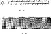
如前面提到的,当发射电极具有相对于基底电极的负偏压时,电子可从发射电极产生。参见图2a至2i,发射电极可具有多种几何形状,如细线2a,具尖端的棒2b,具几个尖端或齿(comb)的棒2c,筛或金属丝网2d,松散盘管2e,排列的齿2f,细线或细丝束2g,表面具尖端突出的棒2h,或表面凸起的板2i。其它几何体也可包括上述几何体的结合如具有表面突起的板或棒,延伸有尖端的板或棒,丝或细丝缠绕的棒,细线丝等。从导电基底延伸出一种或多种电极的实施方式中,电极可从如图2c中所述实施方式的实质上平的基底发射,该基底位于隐藏孔中,或可选择从表面凸起如“U”形或“V”凸起延伸出电极。可使用的大量电极可以并串行(parallel series)或交叉网状格排列。更进一步的几何形状可包括车轮式(wagon wheel)几何体,其中大量的电极以放射方式如轮子的“幅”形式排列。具体的实施方式中,例如涉及场发射的方式中,负极优选具大面积弯曲的几何体组成,如大量尖端以使邻近电极表面的电场最大化,如图3描述的几何体。如图3所示,电极1有一系列位于电极表面凹槽中的细线2和沿电极表面散发的大量尖端3。As mentioned earlier, when the emitter electrode has a negative bias with respect to the substrate electrode, electrons can be generated from the emitter electrode. Referring to Figures 2a to 2i, the emitter electrode can have various geometries, such as a thin wire 2a, a pointed rod 2b, a rod with several points or teeth (comb) 2c, a screen or wire mesh 2d, a loose coil 2e , arrayed teeth 2f, thin wires or filament bundles 2g, rods 2h with protruding points on the surface, or
图11a和11b提供一种电极部件410的实例,该部件位于无焊剂焊接装置400中。具体实施方式中,电极部件410作为发射电极起作用。无焊剂焊接装置400进一步包括至少一种能量源和至少一种气体供应源(未表示)。参见图11a,电极部件410由外壳420和导电基底430组成。外壳420至少部分地含有绝缘材料,例如但不限于陶瓷。另一个实施方式中,外壳420可包含绝缘和导电材料的组合,或者可选择,至少部分用绝缘材料包覆的导电材料。这些后一类实施方式中,与导电基底430接触并面向目标区域440的外壳420部分由绝缘材料组成。外壳420具有内部空间422、与内部空间422流体连通的至少一个的流体入口424,和允许气体混合物穿过电极部件410的气体供应源(未表示)。具体实施方式中,通过至少一个流体入口可将包含体积的4%的氢和平衡量的氮的气体混合物引入外壳420。在图11a,11b和/或11c中,外壳420和导电基底430作为具有圆形横断面来描述的。然而外壳420和导电基底430可具有多种其它的横断面,例如但不限于,正方形,长方形,椭圆形或多种其它形状。11 a and 11 b provide an example of an electrode assembly 410 that is located in a fluxless soldering apparatus 400 . In a specific embodiment, the electrode member 410 functions as an emitter electrode. The fluxless soldering apparatus 400 further includes at least one energy source and at least one gas supply source (not shown). Referring to FIG. 11 a , the electrode part 410 is composed of a casing 420 and a
导电基底430具有许多与内部空间422流体连通的大量小孔432和从其中延伸的大量导电端434。导电基底430可排列,安装,或放置在所示的外壳420中。也可选择的是,导电基底430和外壳420可以是完整的组件。具体实施方式中,当气体混合物通过至少一个流体入口424穿过内部空间422并穿过孔432进入目标区域440时,导电基底430与至少一个能量源(未表示)的电连接产生了附着气体混合物的电子。焊接装置400可进一步包括一种或多种附加电极如接地的基底电极460。如图11a和11b所示的具体实施方式中,在目标区域440中,含有焊料凸起的基片450可放置在基底电极460上。
水和氧杂质可由多种因素如漏气和反应副产物产生。具体实施方式中,目标区域中的这些杂质需要最小化。例如,具体实施方式中,优选目标区域中每百万(ppm)的氧杂质总量低于20份。目标区域的杂质可通过提高气体穿过流体入口424的流动速度达到最小化。Water and oxygen impurities can arise from a variety of factors such as outgassing and reaction by-products. In particular embodiments, these impurities need to be minimized in the target region. For example, in particular embodiments, it is preferred that the total amount of oxygen impurities in the target region be less than 20 parts per million (ppm). Contamination of the target area can be minimized by increasing the flow velocity of the gas through the fluid inlet 424 .
具体实施方式中,大量的导电端434可以这样的方式排列,即导电基底430上导电端的相互排列形成了,如三角形,放射状,正方形,交叉状等。也可选择的是,导电端的排列可以以随机的形式。图11c中举例说明了一种排列类型的实例,其中x,y和z实质上长度相似,从而形成等边三角形。每个导电端的长度、几何形状和其它特征彼此间可不相同。此外,根据象装置生产能力、基片类型、待去除的氧化物量、附加电极的数量、气体混合物的流动速度、至少一种能量源的类型和量这样的非限制性因素来改变导电端的密度。In a specific embodiment, a large number of
作为放射电极起作用的电极材料优选包含相对低电子发射能量或功函的导电材料。材料也优选具有高熔点和在处理条件下具有相对高的稳定性。适宜材料的例子包括金属、合金、半导体、和包覆或沉积在传导基片上的氧化物。进一步的例子包括,但不限于,钨、石墨、高温合金如镍铬合金,以及金属氧化物如沉积在传导基片上的BaO和Al2O3。Electrode materials that function as emissive electrodes preferably comprise conductive materials with relatively low electron emission energy or work function. The material also preferably has a high melting point and relatively high stability under processing conditions. Examples of suitable materials include metals, alloys, semiconductors, and oxides coated or deposited on conductive substrates. Further examples include, but are not limited to, tungsten, graphite, superalloys such as nickel chrome, and metal oxides such as BaO andAl2O3deposited on a conductive substrate.
作为基底电极起作用的电极材料可由导电材料如金属或半导体材料组成。金属或半导体材料的例子包括本文公开的任何材料。一个优选实施方式中,基底电极可由半导体、比如基片自身组成,即回流的晶片可以是基底电极。该实施方式中,基片例如通过接地而起到第二或基底电极的作用,例如,通过接地。另一个实施方式中,基底电极可为导电材料如任何用于发射电极的材料。根据应用基底电极可以有多种不同的几何形状。Electrode materials functioning as substrate electrodes may consist of conductive materials such as metals or semiconductor materials. Examples of metal or semiconductor materials include any of the materials disclosed herein. In a preferred embodiment, the base electrode can be composed of a semiconductor, such as the substrate itself, that is, the reflowed wafer can be the base electrode. In this embodiment, the substrate acts as a second or base electrode, eg by being grounded. In another embodiment, the base electrode can be a conductive material such as any material used for an emitter electrode. Depending on the application, the substrate electrode can have a variety of different geometries.
本发明涉及热-场发射的具体实施方式中,发射电极可包含如图4所述电极的分段部件。在这点上,发射电极的芯10可由具高电阻的金属制得。从芯10发散大量的端点11。端点11可由如本文公开的任何具有相对低电子发射能量或功函的导电材料制得。可采用直接通入AC或DC流(未表示)穿过芯10来加热芯。热传导会从芯至端点11传递热量。热芯10和大量端点11封在壳(enclosure)12中,然后插入支撑架,从而形成所示的分段部件。端点11暴露在壳12外面。壳12由绝缘材料组成。操作过程中,分段部件允许芯的热膨胀。该排列中,通过在相对于基底电极的发射电极上应用负偏压,从热端点11产生电子。In a specific embodiment of the invention involving thermal-field emission, the emitter electrode may comprise a segmented part of the electrode as described in FIG. 4 . In this regard, the
涉及热-场发射的本发明另一个优选实施方式中,间接加热可提高发射电极的温度。这可以利用作为发射电极的芯的加热筒来达到目的。加热筒表面可含有比如与加热筒内的加热元件电绝缘的金属导电材料。为促进电子发射,大量分布的发射端可安装在加热筒表面。可通过使AC或DC流通过筒内的加热元件来加热筒。通过在相对于发射电极的筒表面施加负偏压,可从筒的分布端点产生电子。为在该排列中产生电压,发射电极可接地使得筒可以为负偏压,或可选的,筒可接地使得发射电极可以为正偏压。一些实施方式中,后一种情况是优选的,用于除去两个电路间的潜在干扰,如一个电路可以为沿着加热元件的AC或DC流,另一个电路可以为筒表面和第二电压间的高电压。这些实施方式中,热筒电极也可以作为气体混合物的热源,以达到回流处理步骤所需温度。In another preferred embodiment of the invention involving thermal-field emission, indirect heating increases the temperature of the emitter electrode. This can be achieved with a heating cartridge as the core of the emitter electrode. The heating cartridge surface may contain, for example, a metallic conductive material that is electrically insulated from the heating elements within the heating cartridge. To facilitate electron emission, a large number of distributed emitting terminals can be mounted on the surface of the heating cylinder. The cartridge may be heated by passing AC or DC flow through a heating element within the cartridge. Electrons can be generated from the distributed end points of the cartridge by applying a negative bias to the cartridge surface relative to the emitter electrode. To generate a voltage in this arrangement, the emitter electrode can be grounded so that the barrel can be negatively biased, or alternatively, the barrel can be grounded so that the emitter electrode can be positively biased. In some embodiments, the latter case is preferred to remove potential interference between two circuits, e.g. one circuit may be an AC or DC flow along the heating element and the other circuit may be the cartridge surface and a second voltage high voltage between. In these embodiments, the hot cartridge electrode may also serve as a heat source for the gas mixture to reach the temperature required for the reflow processing step.
如前面提到的,包含还原气体的气体混合物穿过由至少两个电极产生的电场。包含在气体混合物中的还原气体可以为一种或多种下列种类:1)本质上为还原性的气体,2)能产生形成气体氧化物的活性物质的气体,气体氧化物是金属氧化物与活性物质反应产生的,或3)能产生形成液体或气体氧化物的活性物质的气体,液体或气体氧化物是金属氧化物与活性物质反应产生的。As mentioned earlier, the gas mixture comprising the reducing gas is passed through an electric field generated by at least two electrodes. The reducing gas contained in the gas mixture may be one or more of the following species: 1) a gas that is reducing in nature, 2) a gas that produces reactive species that form gaseous oxides, which are metal oxides combined with The reaction of the active material, or 3) the gas of the active material capable of forming a liquid or gaseous oxide, which is produced by the reaction of the metal oxide with the active material.
第一类气体、或本质上为还原性的气体,包括热力学上可作为还原剂用于除去氧化物的任何气体。本质上为还原性的气体包括H2,CO,SiH4,Si2H6,甲酸,醇类如甲醇,乙醇等,以及一些具下式(III)的酸性蒸气:The first class of gases, or gases that are reducing in nature, includes any gas that is thermodynamically available as a reducing agent for oxide removal. Gases that are reducing in nature include H2 , CO, SiH4 , Si2 H6 , formic acid, alcohols such as methanol, ethanol, etc., and some acid vapors with the following formula (III):

式(III)中,取代基R可为烷基,取代的烷基,芳基或取代的芳基。本文使用的术语“烷基”包括直链、支链或环烷基,优选含有1至20个碳原子,或更优选1至10个碳原子。这也适用于包含在其它基团中的烷基部分,如卤烷基、烷芳基或芳烷基。术语“取代的烷基”适用于具有如下取代基的烷基部分:包括杂环原子如O、N、S或卤素原子;OCH3;OR(R=C1-10烷基或C6-10芳基);C1-10烷基或C6-10芳基;NO2;SO3R(R=C1-10烷基或C6-10芳基);或NR2(R=H,C1-10烷基或C6-10芳基)。本文使用的术语“卤素”包括氟、氯、溴和碘。本文使用的术语“芳基”包括芳香性的6至12元碳环。本文使用的术语“取代芳基”包括具有如下取代基的芳环,如杂环原子如O、N、S或卤素原子;OCH3;OR(R=C1-10烷基或C6-10芳基);C1-10烷基或C6-10芳基;NO2;SO3R(R=C1-10烷基或C6-10芳基);或NR2(R=H,C1-10烷基或C6-10芳基)。具体优选的实施方式中,气体混合物含有氢。In formula (III), the substituent R may be an alkyl group, a substituted alkyl group, an aryl group or a substituted aryl group. The term "alkyl" as used herein includes linear, branched or cyclic alkyl groups, preferably containing 1 to 20 carbon atoms, or more preferably 1 to 10 carbon atoms. This also applies to alkyl moieties contained in other groups, such as haloalkyl, alkaryl or aralkyl. The term "substituted alkyl" applies to alkyl moieties having substituents including hetero ring atoms such as O, N, S or halogen atoms; OCH3 ; OR (R=C1-10 alkyl or C6-10 aryl); C1-10 alkyl or C6-10 aryl; NO2 ; SO3 R (R=C1-10 alkyl or C6-10 aryl); or NR2 (R=H, C1-10 alkyl or C6-10 aryl). The term "halogen" as used herein includes fluorine, chlorine, bromine and iodine. The term "aryl" as used herein includes aromatic 6 to 12 membered carbocyclic rings. The term "substituted aryl" as used herein includes aromatic rings having substituents such as hetero ring atoms such as O, N, S or halogen atoms; OCH3 ; OR (R=C1-10 alkyl or C6-10 aryl); C1-10 alkyl or C6-10 aryl; NO2 ; SO3 R (R=C1-10 alkyl or C6-10 aryl); or NR2 (R=H, C1-10 alkyl or C6-10 aryl). In a particularly preferred embodiment, the gas mixture contains hydrogen.
第二类还原气体包括任何本质上无还原性、但可通过电子在气体分子上的游离附着而产生活性物质例如,H、C、S、H’、C’和S’,并且通过活性物质与待去除的金属氧化物反应而形成气体氧化物。这类气体的例子包括NH3,H2S,C1至C10的烃,例如但不限于CH4,C2H4,式(III)的酸性蒸气,和下式(IV)的有机蒸气:The second type of reducing gas includes any essentially non-reducing gas, but can generate active species such as H, C, S, H', C' and S' through the free attachment of electrons on gas molecules, and through the active species and The metal oxides to be removed react to form gaseous oxides. Examples of such gases includeNH3 ,H2S ,C1 toC10 hydrocarbons such as but not limited toCH4 ,C2H4 , acid vapors of formula (III), and organic vaporsof formula (IV) below :
在式(III)和式(IV)中,取代基R可为烷基,取代烷基,芳基或取代芳基。In formula (III) and formula (IV), the substituent R can be an alkyl group, a substituted alkyl group, an aryl group or a substituted aryl group.
第三类还原气体包括任何本质上无还原性、但通过在气体分子上分离附着的电子能形成活性物质例如F,Cl,F’和Cl’,并且通过活性物质与金属氧化物反应而形成液体或含水氧化物的气体。这类气体例子包括含有氟和氯的气体,例如CF4,SF6,CF2Cl2,HCl,BF3,WF6,UF6,SiF3,NF3,CClF3和HF。The third type of reducing gas includes any essentially non-reducing gas, but can form active species such as F, Cl, F' and Cl' by separating attached electrons on gas molecules, and form liquids by reacting active species with metal oxides or gases containing hydrous oxides. Examples of such gases include gases containing fluorine and chlorine, such as CF4 , SF6 , CF2 Cl2 , HCl, BF3 , WF6 , UF6 , SiF3 , NF3 , CClF3 and HF.
除了包括一种和多种上述种类的还原气体外,气体混合物可进一步含有一种或多种载体气体。载体气体可用于,例如,稀释还原气体或提供碰撞稳定性。用于气体混合物中的载体气体可为电子亲和性低于气体混合物中的还原气体或气体混合物中的气体的任何气体。具体的实施方式中,载体气体为惰性气体。适宜的惰性气体的实例包括,但不限于,N2,Ar,He,Ne,Kr,Xe和Rn。In addition to comprising one or more reducing gases of the aforementioned species, the gas mixture may further contain one or more carrier gases. The carrier gas can be used, for example, to dilute the reducing gas or to provide collisional stability. The carrier gas used in the gas mixture can be any gas that has a lower electron affinity than the reducing gas in the gas mixture or the gas in the gas mixture. In a specific embodiment, the carrier gas is an inert gas. Examples of suitable inert gases include, but are not limited to,N2 , Ar, He, Ne, Kr, Xe and Rn.
具体的实施方式中,由于相对低的价格和排出气体的环境友好性,气体混合物含有作为还原气体的氢和作为载体气体的氮。这些实施方式中,气体混合物含有占体积的0.1至100%,或1至50%,或0.1至4%的氢。氢含量低于4%是优选的,这使得气体混合物不易燃。In a specific embodiment, the gas mixture contains hydrogen as the reducing gas and nitrogen as the carrier gas due to the relatively low price and the environmental friendliness of the exhaust gas. In these embodiments, the gas mixture contains 0.1 to 100%, or 1 to 50%, or 0.1 to 4% hydrogen by volume. A hydrogen content of less than 4% is preferred, which renders the gas mixture non-flammable.
具体的实施方式中,在温度范围从室温至450℃,或从100至350℃下,气体混合物穿过由至少两个电极产生的场。气体混合物的压力优选为环境气压,即处理区域本身的压力。无需例如真空的特殊压力。实施方式中,对气体混合物加压,压力范围可以从10至20磅/英寸,或从14至16磅/英寸。In a specific embodiment, the gas mixture is passed through a field generated by at least two electrodes at a temperature ranging from room temperature to 450°C, or from 100 to 350°C. The pressure of the gas mixture is preferably ambient air pressure, ie the pressure of the treatment zone itself. No special pressure such as vacuum is required. In embodiments, the gas mixture is pressurized, which may range from 10 to 20 psig, or from 14 to 16 psig.
氧化物将被去除的基片表面优选位于发射电极和基底电极间,并且表面面向发射电极。本发明的具体优选实施方式中,基片可连接到基底电极以提供目标部件并且面对发射电极。这些实施方式中,发射电极与基片或目标部件的顶部表面的距离范围可以为0.1至30cm,或从0.5至5cm。The surface of the substrate from which the oxide is to be removed is preferably located between the emitter electrode and the base electrode, with the surface facing the emitter electrode. In a particularly preferred embodiment of the invention, a substrate may be attached to the base electrode to provide the target component and face the emitter electrode. In these embodiments, the distance of the emitter electrode from the top surface of the substrate or target component may range from 0.1 to 30 cm, or from 0.5 to 5 cm.
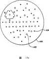
图5提供一种其中基片是硅片20的用于晶片凸起应用的处理实例。参见图5,发射电极24位于硅片20上,包含大量焊料凸起(未表示)的硅片20置于基底电极22上,以形成目标部件。包含大量焊料凸起的硅片20的至少一部分表面暴露在发射电极24下。尽管所示的硅片20置于基底电极22上时,可预见硅片20可被放置在电极22和24之间的任何地方。脉冲电压25被施加在基底电极22和发射电极24以产生电场。包含氢和氮的气体混合物26通过电场。电场产生漂向基底电极22和置于其上的晶片20的低能电子28。此外,通过电子附着,而使得气体混合物26中的部分氢形成的氢离子30,也漂向基底电极22和置于其上的片20。负电氢离子30和电子28向电极22和置于其上的晶片20漂移促进晶片20表面上离子30的吸收,并促进硅片表面的去氧化(这里指表面去氧化)。FIG. 5 provides an example of a process for wafer bumping applications where the substrate is a silicon wafer 20 . Referring to FIG. 5, the emitter electrode 24 is located on a silicon wafer 20, and the silicon wafer 20 including a large number of solder bumps (not shown) is placed on the base electrode 22 to form a target component. At least a portion of the surface of the silicon wafer 20 containing a plurality of solder bumps is exposed under the emitter electrode 24 . Although silicon wafer 20 is shown placed on substrate electrode 22, it is contemplated that silicon wafer 20 may be placed anywhere between electrodes 22 and 24. A pulse voltage 25 is applied to the substrate electrode 22 and the emitter electrode 24 to generate an electric field. A gas mixture 26 comprising hydrogen and nitrogen is passed through the electric field. The electric field produces low energy electrons 28 that drift towards the substrate electrode 22 and the wafer 20 disposed thereon. In addition, hydrogen ions 30 formed from a portion of the hydrogen in the gas mixture 26 by electron attachment also drift towards the substrate electrode 22 and the wafer 20 placed thereon. The drift of negatively charged hydrogen ions 30 and electrons 28 towards the electrode 22 and the wafer 20 placed thereon facilitates the absorption of ions 30 on the surface of the wafer 20 and promotes deoxidation of the silicon wafer surface (referred to herein as surface deoxidation).
根据基片的传导性,一些作为表面去氧化的反应副产物产生的电子可聚集在基片表面上。此外,由于沿着电场漂移,部分自由电子可直接吸收在基片上。基片表面上的电子堆积可阻止负电离子的进一步吸收,并且对表面去氧化的平衡状态有不利的影响。为使表面去氧化处理更高效,基片表面上的电子需要定期除去。Depending on the conductivity of the substrate, some of the electrons generated as a by-product of the surface deoxidation reaction may accumulate on the substrate surface. In addition, part of the free electrons can be absorbed directly on the substrate due to drift along the electric field. Electron accumulation on the substrate surface can prevent further absorption of negatively charged ions and adversely affect the equilibrium state of surface deoxidation. For surface deoxidation to be effective, electrons on the substrate surface need to be removed periodically.
一个去除基片表面电子的方法中,可以改变两个电极彼此之间的极性。在极性改变期间,每个电极上的电压水平不必要相同。一个实施方式中,通过应用如图10b所示的至少两个电极间的双向电压脉冲获得极性改变。图6提供一种极性改变的例子,其中在一个脉冲相中(如负偏压)电极可产生电子,并在另一电压脉冲相中(如正偏压)回收电子。在图6中,电极100作为电子发射和电子回收电极使用,电极102作为基底电极使用。该排列使得表面去氧化的效率达到最大化。包含大量尖端101的电极100置于晶片103上。通过连接到AC电源104加热电极100。另一个电极102置于晶片103下。例如,通过双向脉冲DC源105,可获得电极100和102间极性的改变。双向电压脉冲的例子在图10b中说明。当电极100是负偏压时,至少部分产生于端点101的电子附着在至少部分还原气体上,并且新产生的还原气体离子漂向晶片103。当极性逆转时,从晶片103表面释放电子并在端点101处回收。图7a和7b说明在每个电压脉冲循环期间带电物质的传送。两电极极性改变的频率范围可为0至100kHz。In one method of removing electrons from the surface of the substrate, the polarity of the two electrodes relative to each other can be changed. The voltage levels on each electrode are not necessarily the same during a polarity change. In one embodiment, the polarity change is obtained by applying bi-directional voltage pulses between at least two electrodes as shown in Figure 10b. Figure 6 provides an example of a polarity change where electrons can be generated at an electrode during one pulse phase (eg, negative bias) and electrons can be recovered during another voltage pulse phase (eg, positive bias). In FIG. 6, an
可选的实施方式中,通过使用一种或多种附加的电极可除去基片表面上过量的电子。图8提供了一种其中晶片是基片的例子。参见图8,晶片200置于接地的基底电极201上。相对基底电极201具负偏压的电极202和相对于基底电极201具正偏压的电极203的两个电极,均安装在晶片200的表面上。该排列中,从电极202不断产生电子并在电极203回收。一个优选的实施方式中,电极202和电极203的极性可相对于基底电极201由正偏压到负偏压定期改变,反之亦然。In an alternative embodiment, excess electrons on the substrate surface may be removed by use of one or more additional electrodes. Figure 8 provides an example where the wafer is the substrate. Referring to FIG. 8 , a
然而在另一个实施方式中,通过在表面去氧化后使用中和剂,可从基片表面去除电子或残留的表面电荷。如果不进行处理,残留电荷杂质可引起对灵敏的电子元件有害的静电放电。这些实施方式中,高纯度气体如N2流动通过商业上可得到的中和器,然后穿过基片表面可中和晶片表面的残留电荷。气体中存在的正离子会中和任何残留电子并提供电中性的表面。例如,适宜的电子中和器可以由在气体中产生等密度的正离子和负离子的Kr-85放射源组成。尽管气体流经片时产生了正离子和负离子,但是气流净电荷为零。In another embodiment, however, electrons or residual surface charge can be removed from the substrate surface by using a neutralizing agent after the surface has been deoxidized. Left untreated, residual charge impurities can cause electrostatic discharges that are harmful to sensitive electronic components. In these embodiments, a high purity gas such asN2 is flowed through a commercially available neutralizer and then across the substrate surface to neutralize residual charge on the wafer surface. The presence of positive ions in the gas neutralizes any remaining electrons and provides an electrically neutral surface. For example, a suitable electron neutralizer may consist of a Kr-85 radiation source that produces an isodensity of positive and negative ions in the gas. Although positive and negative ions are generated as the gas flows over the sheet, the net charge of the gas flow is zero.
具体实施方式中,基片或目标部件可相对于作为发射电极的电极移动。在这点上,发射电极可在固定的位置上和基片可移动,发射电极可移动和基片可在固定的位置上,或者发射电极和基片都可移动。移动可以是直线的、水平的、旋转的或沿着弧形的移动。这些实施方式中,在基片表面的局部区域可发生表面去氧化。In a specific embodiment, the substrate or target part is movable relative to the electrode which acts as the emitting electrode. In this regard, the emitting electrode may be at a fixed position and the substrate may be movable, the emitting electrode may be movable and the substrate may be at a fixed position, or both the emitting electrode and the substrate may be movable. Movement can be linear, horizontal, rotational or along an arc. In these embodiments, surface deoxidation may occur in localized regions of the substrate surface.
对于下列的图9a至9e,基片是置于接地的基底电极上的硅片。包含大量焊料凸起(未表示)的至少部分晶片表面暴露于发射电极,即作为发射电极和回收电极起作用的电极(如改变极性,例如,使电位由负偏压到电压)。图9a显示在加热的线电极302下旋转移动的硅片300,该电极302被相对于基底电压304施加了双向脉冲电压,该电压可以0至100KHz的频率下循环,从而产生如306所示的离子区域。位于处理箱(未表示)外部的发动机使晶片旋转。这种通常在半导体处理中完成的旋转不会严重污染片表面。通过采用高清洁度的旋转进料槽和控制流动方式可避免污染。图9b显示在热的线电极312下直线移动的硅片310,该电极312被相对于基底电极314施加了双向脉冲电压,从而产生如316所示的离子区域。该排列适用于利用传送带使晶片移动通过管状起凸炉(bumping fumaces)的应用,例如,印刷电路板穿过回流炉。图9c显示在一对热的线发射电极324和326下旋转移动的硅片320:基底电极322具有稳定正偏压,发射电极324和326具有相对于基底电极322的稳定负偏压,使得产生电子并从片表面回收,从而产生如328所示的离子区域。位于处理箱(未表示)外部的发动机使晶片旋转。图9d显示在一对热的线电极334和336下直线移动的硅片330,所述电极保持稳定并具有相对于基底电极332的相反极性,分别进行电子发射和回收,从而产生如338所示的离子区域。最后,图9e使用位于枢轴臂346末端的相对小的电极344。电极344的极性相对于基底电极342不断改变,从而产生如348所示的离子区域。该臂在旋转晶片340上摇摆,例如弧形运动,从而对整个晶片表面进行彻底和均一的处理。For the following Figures 9a to 9e, the substrate is a silicon wafer placed on a grounded base electrode. At least a portion of the wafer surface containing a plurality of solder bumps (not shown) is exposed to the emitter electrode, an electrode that functions as an emitter electrode and as a recovery electrode (eg, changes polarity, eg, biases the potential from negative to voltage). Figure 9a shows a silicon wafer 300 in rotational motion under a heated wire electrode 302 to which a bidirectional pulsed voltage is applied relative to a substrate voltage 304, which can be cycled at a frequency from 0 to 100 KHz to produce ion region. A motor located outside the processing box (not shown) spins the wafers. This rotation, which is commonly done in semiconductor processing, does not seriously contaminate the wafer surface. Contamination is avoided by using a high-cleanliness rotary feed chute and controlled flow. FIG. 9 b shows a silicon wafer 310 linearly moving under a heated wire electrode 312 to which a bidirectional pulsed voltage is applied relative to a substrate electrode 314 , thereby creating an ionic region as shown at 316 . This arrangement is suitable for applications where conveyor belts are used to move wafers through tubular bumping fumaces, for example, printed circuit boards through reflow ovens. Figure 9c shows a silicon wafer 320 moving in rotation under a pair of heated wire emitter electrodes 324 and 326: the base electrode 322 has a stable positive bias and the emitter electrodes 324 and 326 have a stable negative bias relative to the base electrode 322 such that Electrons are recovered from the surface of the sheet, thereby creating an ion region as shown at 328. A motor located outside the processing box (not shown) spins the wafers. Figure 9d shows silicon wafer 330 moving linearly under a pair of heated wire electrodes 334 and 336, which are held steady and have opposite polarity with respect to substrate electrode 332, for electron emission and recovery, respectively, thereby producing The ion region shown. Finally, FIG. 9e uses a relatively small electrode 344 at the end of a pivot arm 346 . The polarity of electrode 344 is constantly changing relative to substrate electrode 342 , thereby creating an ionic region as shown at 348 . The arm rocks, eg, in an arcuate motion, over the rotating wafer 340 to provide a thorough and uniform treatment of the entire wafer surface.
除了焊料凸起晶片的回流外,本发明的方法可用于微电子制造的几个领域,例如,表面清洁、金属电镀、铜焊、焊接、用于外部引线焊接的回流焊接和波动焊接。适合于本发明方法的回流和波动焊接装置的例子示于图1-3中,所述图在悬而未决的美国申请09/949,580中公开,该申请转让给了本发明的受让人,本文结合该申请的的全部内容作为参考。一个优选的实施方式中,本发明的方法可用于减少金属表面氧化物,如在硅片处理过程中或薄膜去氧化过程中形成的铜氧化物。作为各种湿处理步骤的结果可形成这种氧化物,如用于在片上形成微电子器件的化学机械平面化(planarization)。这种表面氧化物降低器件的产量和器件安全性。本发明以完全干燥的、环境友好的方式去除表面氧化物,无需使用含水还原剂。此外,既然本发明以相对低的温度来实施,这不会严重影响处理期间装置的热预算。与之相比的,由于产生掺杂物和氧化物的扩散,更高温度有降低器件的产量和器件安全性的趋势,从而降低器件性能。既然本发明的方法可在单晶片上进行,该方法可与其它单晶片处理结合,从而提供与其它制造步骤更好的相容性。In addition to reflow of solder bumped wafers, the method of the present invention can be used in several areas of microelectronics manufacturing, such as surface cleaning, metal plating, brazing, soldering, reflow soldering for external lead soldering, and wave soldering. Examples of reflow and wave soldering apparatus suitable for the method of the present invention are shown in FIGS. 1-3, which are disclosed in co-pending U.S. Application Serial No. 09/949,580, assigned to the assignee of the present invention, incorporated herein by reference. The entire content of the application is incorporated by reference. In a preferred embodiment, the method of the present invention can be used to reduce oxides on metal surfaces, such as copper oxides formed during silicon wafer processing or thin film deoxidation. Such oxides may form as a result of various wet processing steps, such as chemical mechanical planarization for forming microelectronic devices on wafers. Such surface oxides reduce device yield and device safety. The present invention removes surface oxides in a completely dry, environmentally friendly manner without the use of aqueous reducing agents. Furthermore, since the invention is implemented at relatively low temperatures, this does not significantly impact the thermal budget of the device during processing. In contrast, higher temperatures tend to reduce device yield and device safety due to diffusion of dopants and oxides, thereby reducing device performance. Since the method of the present invention can be performed on a single wafer, the method can be combined with other single wafer processing, thereby providing better compatibility with other fabrication steps.
本发明的方法和装置特别适合晶片凸起和薄膜去氧化应用。本发明用于晶片凸起和薄膜去氧化有很多有益之处。首先,相对于外部引线焊接的传统回流焊接处理而言,晶片凸起和薄膜去氧化都是单面处理。与此有关的是,去氧化的表面上的空间可为小至1cm,从而引起对离子产生和传送的有效处理。第二,晶片凸起中的回流处理温度明显高于传统回流焊接处理。更高的温度促进了通过电子附着形成负电离子。第三,在晶片凸起和薄膜去氧化处理中,焊料凸起和薄膜完全暴露,从而使得表面去氧化期间任何“盲区”效果最小化。此外,相比其它焊料必须湿润并且散布在元件表面的焊接处理而言,晶片上沉积的焊料凸起仅需要通过第一次回流而形成焊球。The method and apparatus of the present invention are particularly suitable for wafer bumping and thin film deoxidation applications. The present invention has many benefits for wafer bumping and thin film deoxidation. First, both wafer bumping and film deoxidation are single-sided processes compared to traditional reflow soldering processes for external lead soldering. In relation to this, the space on the deoxidized surface can be as small as 1 cm, resulting in efficient handling of ion generation and transport. Second, the reflow process temperature in wafer bumping is significantly higher than conventional reflow soldering processes. Higher temperatures promote the formation of negatively charged ions through electron attachment. Third, during the wafer bump and film deoxidization process, the solder bumps and film are fully exposed, thereby minimizing any "dead zone" effects during surface deoxidation. Furthermore, solder bumps deposited on the wafer need only pass through the first reflow to form solder balls, compared to other soldering processes where the solder must wet and spread over the component surface.
根据下面的实施例对本发明作更详细的说明,但不应理解为本发明限于此。The present invention will be described in more detail based on the following examples, but it should not be construed that the present invention is limited thereto.
实施例1Example 1
利用实验室规模的炉进行第一个试验。所用的样品是在接地的铜片(正极)上的无焊剂锡-铅焊料预制品(熔点183℃),在N2中5%的H2气流下,将之装入炉内并加热至250℃。当样品温度为平衡状态时,在负电极(负极)和接地样品(正极)间使用DC电压,并且以0.3mA的电流使电压逐渐升高至约-2kV。两电极间的距离约1cm。压力为环境气压。发现铜表面上的焊料的确非常润湿。在如此低温下,不使用电压,在铜表面上不能获得良好的无焊剂焊料润湿,甚至在纯H2中,因为在锡基焊料上用纯H2除去锡氧化物的有效温度为高于350℃。因此,该结果表明在促进H2无焊剂焊接中电子附着方法是有效的。A first experiment was performed using a laboratory scale furnace. The sample used was a flux-free tin-lead solder preform (melting point 183°C) on a grounded copper sheet (positive terminal), which was loaded into a furnace and heated to 250°C under a flow of 5%H2 inN2 . ℃. When the sample temperature was in equilibrium, a DC voltage was applied between the negative electrode (cathode) and the grounded sample (positive pole), and the voltage was gradually increased to about -2 kV with a current of 0.3 mA. The distance between the two electrodes is about 1 cm. Pressure is ambient air pressure. It was found that the solder on the copper surface was indeed very wet. At such low temperatures, without application of voltage, good fluxless solder wetting cannot be obtained on copper surfaces, even in pureH2 , since the effective temperature for removal of tin oxides with pureH2 on tin-based solders is higher than 350°C. Therefore, this result indicates that the electron attachment method is effective in promotingH2 fluxless soldering.
实施例2Example 2
利用与实施例1相同的装置并且利用场发射机理,研究了用于氢促进的电子附着无焊剂焊接的几种阴极极材料。研究结果列于表I中。Using the same setup as in Example 1 and utilizing the field emission mechanism, several cathode electrode materials for hydrogen-promoted electron attachment fluxless soldering were investigated. The results of the study are listed in Table I.
如表I所示,获得最佳的结果是通过利用Ni/Cr阴极,该阴极提供最高的助熔(fluxing)效率,从而引起最短的润湿时间。确信Ni/Cr阴极产生与其它负极材料相比相对更大量的电子和适宜的电子能级。As shown in Table I, the best results were obtained by using a Ni/Cr cathode, which provided the highest fluxing efficiency, resulting in the shortest wetting time. It is believed that the Ni/Cr cathode produces a relatively larger amount of electrons and a suitable electron energy level compared to other negative electrode materials.
表I:250℃和20%的H2下,阴极材料对润湿时间的影响Table I: Effect of cathode material on wetting time at 250°C and 20%H2
实施例3Example 3
进行本实施例研究产生电子的热-场发射方法的效率。从棒表面突出大量1mm长机加工端的直径为3mm的石墨棒作为阴极,并且它的几何形状与图2i中描述的棒相似。每个突出的机加工端的顶锥角为25度。利用AC能源电阻加热,在5%H2和95%N2的气体混合物中,将石墨棒加热至约400至500℃。在1.5cm间隔的石墨阴极和作为阳极的铜片间施加5KV的DC电压源。石墨上所有的端点都照明(illuminated)了,从而表示电子可从石墨棒的分布端均一地产生。不加热石墨棒,则从阴极无电子发射,或者一个端点和阳极片间发生击穿。这表明利用具大量端点的阴极和升高温度相结合,即热-场发射方法,对于从集成发射系统获得均一的电子发射是有效的。This example was carried out to investigate the efficiency of the thermal-field emission method of generating electrons. A large 3 mm diameter graphite rod protruding from the rod surface with a 1 mm long machined end served as the cathode, and its geometry was similar to the rod described in Fig. 2i. Each protruding machined end has a tip taper angle of 25 degrees. Using AC energy resistance heating, graphite rods are heated to about 400 to 500 °C in a gas mixture of 5%H2 and 95%N2 . A DC voltage source of 5KV was applied between graphite cathodes at 1.5cm intervals and copper sheets as anodes. All endpoints on the graphite are illuminated, indicating that electrons can be generated uniformly from distributed ends of the graphite rod. Without heating the graphite rod, there is no electron emission from the cathode, or a breakdown occurs between one end and the anode sheet. This shows that the use of a cathode with a large number of endpoints combined with elevated temperature, ie, the thermal-field emission approach, is effective for obtaining uniform electron emission from an integrated emission system.
实施例4Example 4
利用直径为0.04”并且水平夹紧在两个机加工的Al2O3耐熔片间的镍铬合金电热丝,如图4中描述的电极,来进行本实施例。每个丝末端均具有尖端(12.5度)的5个串连镍铬合金发射丝,从镍铬合金电热丝垂直突出并且垂直位于两个耐熔片间。利用AC能源,在5%H2和95%N2的气体混合物中,将镍铬合金电热丝和端点都加热至约870℃。在6mm间隔的阴极和作为阳极的铜片间施加2.6KV的DC电压源。5个端点都照明了,并且总的放射电流达到2.4mA。不加热该丝,则从阴极无电子发射,或者一个端点和阳极片间的击穿。如实施例3一样,实施例4证实了热辅助场发射提供均一的电子发射。此外,由于发射电极的更高温度,这也增加在既定电势下的电子发射数量。This example was carried out using Nichrome heating wires 0.04" in diameter and clamped horizontally between two machinedAl2O3 refractory sheets, such as the electrodesdepicted in Figure 4. Each wire end has 5 Nichrome emitting wires in series at the tip (12.5 degrees), protruding vertically from the Nichrome heating wire and vertically located between two refractory plates.Using AC energy, in the gas of 5% H2 and 95% N2 In the mixture, the nickel-chromium alloy heating wire and the terminal are heated to about 870 ° C. A 2.6KV DC voltage source is applied between the cathode at a distance of 6 mm and the copper sheet as the anode. All 5 terminals are illuminated, and the total emission current Reach 2.4mA.Do not heat this silk, then there is no electron emission from cathode, perhaps the breakdown between an end point and anode sheet.As embodiment 3, embodiment 4 has confirmed that heat-assisted field emission provides uniform electron emission.In addition, This also increases the number of electrons emitted at a given potential due to the higher temperature of the emitting electrode.
实施例5Example 5
进行本实施例来证明两电极间电压脉冲对阴极发射的影响。单端的镍铬合金丝作为发射电极使用,接地的铜片作为基底电极起作用。铜片位于发射电极端下3mm处,锡/铅焊料预制品置于铜片上。室温下,在5%H2和余量的N2的气体混合物中,镍铬丝、预制品和铜片保存在熔炉中。在两电极间施用各种频率和振幅的脉冲单向电压。此时,发射电极的电势相对于接地的基底电极可从负数到零改变,从而引起电子从端电极产生。结果示于表II中。This example was performed to demonstrate the effect of voltage pulses between two electrodes on cathode emission. A single-ended nichrome wire acts as the emitter electrode, and a grounded copper sheet acts as the base electrode. A copper sheet is located 3 mm below the emitter electrode tip, and a tin/lead solder preform is placed on the copper sheet. Nichrome wires, preforms and copper sheets are kept in a furnace at room temperature in a gas mixture of 5%H2 and the balance ofN2 . Pulsed unidirectional voltages of various frequencies and amplitudes are applied between the two electrodes. At this time, the potential of the emitter electrode may change from negative to zero with respect to the grounded substrate electrode, thereby causing electrons to be generated from the terminal electrode. The results are shown in Table II.
表II的结果表明:当使用更高的脉冲频率和振幅时,从发射电极产生更大量的电子。The results in Table II show that a greater amount of electrons are generated from the emitting electrode when higher pulse frequencies and amplitudes are used.
表II:单向电压脉冲Table II: Unidirectional Voltage Pulses
实施例6Example 6
进行本实施例来证明通过利用与实施例5的相同装置改变两个电极极性的表面放电。This example was carried out to demonstrate surface discharge by changing the polarity of two electrodes using the same apparatus as in Example 5.
在两个电极间使用3.4kV的总脉冲振幅的双向电压脉冲(如从+1.7kV至-1.7kV)。双向电压脉冲期间,两电极的极性改变。换句话说,发射电极的端点从相对于接地的基底电极的正偏压改变成负偏压,从而使得从该电极产生电子并从端电极回收电子。Bidirectional voltage pulses (eg, from +1.7 kV to -1.7 kV) with a total pulse amplitude of 3.4 kV are used between the two electrodes. During a bidirectional voltage pulse, the polarity of the two electrodes changes. In other words, the terminal of the emitter electrode is changed from a positive bias to a negative bias with respect to the grounded substrate electrode, so that electrons are generated from the electrode and electrons are recovered from the terminal electrode.
表III表示对于极性改变的每个频率下的来自基底电压的泄漏电流。如表III所示,极性改变的频率越高,通过观察穿过铜基底电极的泄漏电流而得到的电荷堆积越少。Table III shows the leakage current from the substrate voltage for each frequency of polarity change. As shown in Table III, the higher the frequency of the polarity change, the less the charge build-up observed by the leakage current through the copper base electrode.
表III:双向电压脉冲Table III: Bidirectional Voltage Pulses
实施例7Example 7
进行本实施例来证明使用附加的电极的远距离表面放电。熔点为305℃的90Pb/10Sn焊料预制品放在小块铜基片上,铜基片放在电绝缘晶片上。接地的铜片置于晶片下并作为基底电极起作用。两个单端点的镍铬丝一个具负偏压而另一个具正偏压,利用焊料预制品将它们都设置在基底电极上1cm处。两个单端点电极间的距离是1.5cm。将该装配在N2中包含4%的H2的气体混合物中从室温加热至焊料熔点以上的回流温度。当回流温度达到平衡,通过施加正极和负极电压到两个单端点电极开始电子附着,并且记录焊料预制品形成球状物的所需时间。球状焊料的形成表明形成了没有氧化物的焊料表面。如表IV所示,在温度范围为310至330℃时,表面去氧化是相当有效的,而该温度仅高于焊料熔点5至15℃。This example was performed to demonstrate remote surface discharge using additional electrodes. A 90Pb/10Sn solder preform with a melting point of 305°C was placed on a small copper substrate placed on an electrically insulating wafer. A grounded copper strip is placed under the die and functions as the base electrode. Two single-ended nichrome wires, one negatively biased and the other positively biased, were both positioned 1 cm above the base electrode using solder preforms. The distance between two single-ended electrodes is 1.5 cm. The assembly was heated from room temperature to a reflow temperature above the melting point of the solder in a gas mixture containing 4%H2 inN2 . When the reflow temperature reached equilibrium, electron attachment was initiated by applying positive and negative voltages to the two single-terminal electrodes, and the time required for the solder preform to form a ball was recorded. The formation of spherical solder indicates the formation of an oxide-free solder surface. As shown in Table IV, surface deoxidation is quite effective in the temperature range of 310 to 330°C, which is only 5 to 15°C above the melting point of the solder.
表IVTable IV
实施例8Example 8
利用与实施例1类似的装置,在用N2换气的恒定电场下测定发射端点的寿命。在~2.2KV/cm的恒定场,端点发射保持在0.3mA超过上千小时。该结果证实了由于无离子和电子侵蚀而使得场发射端点长的持久性能,。Using a setup similar to Example 1, the lifetime of the emitting endpoint was determined under a constant electric field purged withN2 . At a constant field of -2.2 KV/cm, the endpoint emission remains at 0.3 mA for over thousands of hours. This result confirms the long-lasting performance of the field emission endpoint due to the absence of ion and electron erosion.
然而根据本发明的详细描述和相关的具体实施例,在不偏离本发明的宗旨和范围下,对本发明可进行各种改变和修改对于本领域技术人员来说是显而易见的。However, according to the detailed description and related specific embodiments of the present invention, it will be obvious to those skilled in the art that various changes and modifications can be made to the present invention without departing from the spirit and scope of the present invention.
Claims (23)


Applications Claiming Priority (6)
| Application Number | Priority Date | Filing Date | Title |
|---|---|---|---|
| US10/425,405US7387738B2 (en) | 2003-04-28 | 2003-04-28 | Removal of surface oxides by electron attachment for wafer bumping applications |
| US10/425405 | 2003-04-28 | ||
| US10/425,405 | 2003-04-28 | ||
| US10/819,225US7563380B2 (en) | 2003-04-28 | 2004-04-07 | Electrode assembly for the removal of surface oxides by electron attachment |
| US10/819,225 | 2004-04-07 | ||
| US10/819225 | 2004-04-07 |
Related Child Applications (1)
| Application Number | Title | Priority Date | Filing Date |
|---|---|---|---|
| CN200610101858ADivisionCN100577881C (en) | 2003-04-28 | 2004-04-28 | Method for removing copper oxide films from treated surfaces of substrates |
Publications (2)
| Publication Number | Publication Date |
|---|---|
| CN1551322A CN1551322A (en) | 2004-12-01 |
| CN1316580Ctrue CN1316580C (en) | 2007-05-16 |
Family
ID=32993967
Family Applications (1)
| Application Number | Title | Priority Date | Filing Date |
|---|---|---|---|
| CNB2004100477750AExpired - LifetimeCN1316580C (en) | 2003-04-28 | 2004-04-28 | Electrode parts that remove surface oxides by electron attachment |
Country Status (6)
| Country | Link |
|---|---|
| EP (1) | EP1475179B1 (en) |
| JP (1) | JP4460349B2 (en) |
| KR (1) | KR100638195B1 (en) |
| CN (1) | CN1316580C (en) |
| CA (1) | CA2465195C (en) |
| TW (1) | TWI240765B (en) |
Families Citing this family (16)
| Publication number | Priority date | Publication date | Assignee | Title |
|---|---|---|---|---|
| US8361340B2 (en)* | 2003-04-28 | 2013-01-29 | Air Products And Chemicals, Inc. | Removal of surface oxides by electron attachment |
| US7897029B2 (en) | 2008-03-04 | 2011-03-01 | Air Products And Chemicals, Inc. | Removal of surface oxides by electron attachment |
| US7387738B2 (en) | 2003-04-28 | 2008-06-17 | Air Products And Chemicals, Inc. | Removal of surface oxides by electron attachment for wafer bumping applications |
| US20050241671A1 (en)* | 2004-04-29 | 2005-11-03 | Dong Chun C | Method for removing a substance from a substrate using electron attachment |
| US7247579B2 (en)* | 2004-12-23 | 2007-07-24 | Lam Research Corporation | Cleaning methods for silicon electrode assembly surface contamination removal |
| US8454850B2 (en)* | 2009-09-02 | 2013-06-04 | Air Products And Chemicals, Inc. | Method for the removal of surface oxides by electron attachment |
| JP2012068579A (en)* | 2010-09-27 | 2012-04-05 | Toppan Printing Co Ltd | Method and device for cleaning photomask |
| CN101993034A (en)* | 2010-11-03 | 2011-03-30 | 深港产学研基地 | Method for hermetically sealing high-cleanliness MEMS device |
| US9006975B2 (en)* | 2011-02-09 | 2015-04-14 | Air Products And Chemicals, Inc. | Apparatus and method for removal of surface oxides via fluxless technique involving electron attachment |
| US9205509B2 (en)* | 2011-08-31 | 2015-12-08 | General Electric Company | Localized cleaning process and apparatus therefor |
| CN106637267A (en)* | 2015-10-28 | 2017-05-10 | 通用电气公司 | Method and device for removing oxide from metal substrate |
| CN112670149B (en)* | 2019-10-15 | 2025-06-24 | 北京烁科中科信电子装备有限公司 | A method for eliminating electrode charge accumulation |
| JP6879482B1 (en)* | 2020-01-09 | 2021-06-02 | 株式会社オリジン | Manufacturing method of oxide-removed parts and oxide removal equipment |
| CN111681972B (en)* | 2020-06-19 | 2024-03-15 | 中国航空无线电电子研究所 | Frock assisting gold removal of mounted chip with pins and Jin Tangxi removal method |
| CN112992701B (en)* | 2021-04-23 | 2021-07-16 | 度亘激光技术(苏州)有限公司 | Packaging method of semiconductor device and semiconductor device |
| CN113546761B (en)* | 2021-07-21 | 2023-01-13 | 深圳市天得一环境科技有限公司 | Composite discharge electrode, corona strengthening mechanism and purifying equipment |
Citations (4)
| Publication number | Priority date | Publication date | Assignee | Title |
|---|---|---|---|---|
| US5433820A (en)* | 1992-10-30 | 1995-07-18 | L'air Liquide, Societe Anonyme Pour L'etude Et L'exploitation Des Procedes Georges Claude | Method and apparatus for dry process fluxing |
| CN1110937A (en)* | 1993-12-15 | 1995-11-01 | 乔治·克劳德方法的研究开发空气股份有限公司 | Method and device for dry fluxing of metallic surfaces before soldering or tinning |
| CN1143554A (en)* | 1995-06-09 | 1997-02-26 | 乔治·克劳德方法的研究开发空气股份有限公司 | Method for dry fluxing of metallic surface, before soldering or tinning, using atmosphere which includes water vapour |
| WO2001014963A1 (en)* | 1999-08-19 | 2001-03-01 | National Instruments Corporation | Graphical programming system with distributed block diagram execution and user interface display |
Family Cites Families (14)
| Publication number | Priority date | Publication date | Assignee | Title |
|---|---|---|---|---|
| JPS62256840A (en)* | 1986-04-30 | 1987-11-09 | Toyoda Gosei Co Ltd | Electrode for corona discharge |
| JPH01307225A (en)* | 1988-06-06 | 1989-12-12 | Hitachi Ltd | Negative ion generation method and substrate processing method |
| GB8827933D0 (en)* | 1988-11-30 | 1989-01-05 | Plessey Co Plc | Improvements relating to soldering processes |
| JP3221008B2 (en)* | 1991-07-25 | 2001-10-22 | 株式会社ブリヂストン | Surface treatment method and apparatus |
| US5409543A (en)* | 1992-12-22 | 1995-04-25 | Sandia Corporation | Dry soldering with hot filament produced atomic hydrogen |
| JPH08209353A (en)* | 1995-02-03 | 1996-08-13 | Technova:Kk | Plasma-process and device therefor |
| FR2735053B1 (en)* | 1995-06-09 | 1997-07-25 | Air Liquide | METHOD AND DEVICE FOR WAVE BRAZING INCORPORATING DRY FLUXING OPERATION |
| JPH11214320A (en)* | 1998-01-20 | 1999-08-06 | Handotai Process Kenkyusho:Kk | Method for forming impurity region in semiconductor layer and apparatus for implanting impurity |
| JP2000311868A (en)* | 1999-04-27 | 2000-11-07 | Canon Inc | Surface treatment apparatus and method using negative ions, and method for manufacturing semiconductor device |
| JP2000311940A (en)* | 1999-04-27 | 2000-11-07 | Canon Inc | Processing apparatus and semiconductor device manufacturing method |
| JP4112821B2 (en)* | 2001-06-01 | 2008-07-02 | 松下電器産業株式会社 | Plasma processing method and plasma processing apparatus |
| JP2002361028A (en)* | 2001-06-12 | 2002-12-17 | Daikin Ind Ltd | Plasma reactor and air purification device |
| JP4580590B2 (en)* | 2001-06-21 | 2010-11-17 | パナソニック株式会社 | Flux removal method and apparatus |
| US6776330B2 (en)* | 2001-09-10 | 2004-08-17 | Air Products And Chemicals, Inc. | Hydrogen fluxless soldering by electron attachment |
- 2004
- 2004-04-26CACA2465195Apatent/CA2465195C/ennot_activeExpired - Fee Related
- 2004-04-27TWTW093111791Apatent/TWI240765B/ennot_activeIP Right Cessation
- 2004-04-27EPEP04010015.8Apatent/EP1475179B1/ennot_activeExpired - Lifetime
- 2004-04-28KRKR1020040029400Apatent/KR100638195B1/ennot_activeExpired - Fee Related
- 2004-04-28CNCNB2004100477750Apatent/CN1316580C/ennot_activeExpired - Lifetime
- 2004-04-28JPJP2004134190Apatent/JP4460349B2/ennot_activeExpired - Fee Related
Patent Citations (4)
| Publication number | Priority date | Publication date | Assignee | Title |
|---|---|---|---|---|
| US5433820A (en)* | 1992-10-30 | 1995-07-18 | L'air Liquide, Societe Anonyme Pour L'etude Et L'exploitation Des Procedes Georges Claude | Method and apparatus for dry process fluxing |
| CN1110937A (en)* | 1993-12-15 | 1995-11-01 | 乔治·克劳德方法的研究开发空气股份有限公司 | Method and device for dry fluxing of metallic surfaces before soldering or tinning |
| CN1143554A (en)* | 1995-06-09 | 1997-02-26 | 乔治·克劳德方法的研究开发空气股份有限公司 | Method for dry fluxing of metallic surface, before soldering or tinning, using atmosphere which includes water vapour |
| WO2001014963A1 (en)* | 1999-08-19 | 2001-03-01 | National Instruments Corporation | Graphical programming system with distributed block diagram execution and user interface display |
Also Published As
| Publication number | Publication date |
|---|---|
| EP1475179A3 (en) | 2006-04-05 |
| EP1475179A2 (en) | 2004-11-10 |
| TW200427873A (en) | 2004-12-16 |
| CA2465195C (en) | 2012-06-19 |
| KR100638195B1 (en) | 2006-10-26 |
| CA2465195A1 (en) | 2004-10-28 |
| TWI240765B (en) | 2005-10-01 |
| JP4460349B2 (en) | 2010-05-12 |
| KR20040093446A (en) | 2004-11-05 |
| EP1475179B1 (en) | 2014-11-19 |
| JP2005002468A (en) | 2005-01-06 |
| CN1551322A (en) | 2004-12-01 |
Similar Documents
| Publication | Publication Date | Title |
|---|---|---|
| US8617352B2 (en) | Electrode assembly for the removal of surface oxides by electron attachment | |
| US7977598B2 (en) | Apparatus and method for removal of surface oxides via fluxless technique involving electron attachment and remote ion generation | |
| EP2119526B1 (en) | Method of and apparatus for removal of surface oxides by electron attachment using two groups of electrodes electrically connected to opposed sources | |
| CN1316580C (en) | Electrode parts that remove surface oxides by electron attachment | |
| KR101323951B1 (en) | Apparatus and method for removal of surface oxides via fluxless technique involving electron attachment | |
| EP1473105B1 (en) | Method for removal of surface oxide via fluxless technique involving electron attachement and remote ion generation | |
| US7897029B2 (en) | Removal of surface oxides by electron attachment | |
| SG187373A1 (en) | Apparatus and method for removal of surface oxides via fluxless technique involving electron attachment |
Legal Events
| Date | Code | Title | Description |
|---|---|---|---|
| C06 | Publication | ||
| PB01 | Publication | ||
| C10 | Entry into substantive examination | ||
| SE01 | Entry into force of request for substantive examination | ||
| C14 | Grant of patent or utility model | ||
| GR01 | Patent grant | ||
| ASS | Succession or assignment of patent right | Owner name:AIR PROD & CHEM Free format text:FORMER OWNER: AIR PROD + CHEM; BTU INTERNATIONAL CO., LTD. Effective date:20081024 | |
| C41 | Transfer of patent application or patent right or utility model | ||
| TR01 | Transfer of patent right | Effective date of registration:20081024 Address after:American Pennsylvania Patentee after:Air Products and Chemicals, Inc. Address before:Pennsylvania, America Co-patentee before:BTU International, Inc. Patentee before:Air Products and Chemicals, Inc. | |
| CX01 | Expiry of patent term | Granted publication date:20070516 | |
| CX01 | Expiry of patent term |