CN1312468C - Optoelectronic dust sensor and air conditioning equipment in which such optoelectronic dust sensor is installed - Google Patents
Optoelectronic dust sensor and air conditioning equipment in which such optoelectronic dust sensor is installedDownload PDFInfo
- Publication number
- CN1312468C CN1312468CCNB2004100315671ACN200410031567ACN1312468CCN 1312468 CCN1312468 CCN 1312468CCN B2004100315671 ACNB2004100315671 ACN B2004100315671ACN 200410031567 ACN200410031567 ACN 200410031567ACN 1312468 CCN1312468 CCN 1312468C
- Authority
- CN
- China
- Prior art keywords
- dust
- main body
- light
- photoelectric
- light receiving
- Prior art date
- Legal status (The legal status is an assumption and is not a legal conclusion. Google has not performed a legal analysis and makes no representation as to the accuracy of the status listed.)
- Expired - Fee Related
Links
Images

Classifications
- G—PHYSICS
- G01—MEASURING; TESTING
- G01N—INVESTIGATING OR ANALYSING MATERIALS BY DETERMINING THEIR CHEMICAL OR PHYSICAL PROPERTIES
- G01N21/00—Investigating or analysing materials by the use of optical means, i.e. using sub-millimetre waves, infrared, visible or ultraviolet light
- G01N21/17—Systems in which incident light is modified in accordance with the properties of the material investigated
- G01N21/47—Scattering, i.e. diffuse reflection
- G01N21/49—Scattering, i.e. diffuse reflection within a body or fluid
- G01N21/53—Scattering, i.e. diffuse reflection within a body or fluid within a flowing fluid, e.g. smoke
- G—PHYSICS
- G01—MEASURING; TESTING
- G01N—INVESTIGATING OR ANALYSING MATERIALS BY DETERMINING THEIR CHEMICAL OR PHYSICAL PROPERTIES
- G01N15/00—Investigating characteristics of particles; Investigating permeability, pore-volume or surface-area of porous materials
- G01N15/06—Investigating concentration of particle suspensions
- G01N15/075—Investigating concentration of particle suspensions by optical means
- G—PHYSICS
- G01—MEASURING; TESTING
- G01N—INVESTIGATING OR ANALYSING MATERIALS BY DETERMINING THEIR CHEMICAL OR PHYSICAL PROPERTIES
- G01N21/00—Investigating or analysing materials by the use of optical means, i.e. using sub-millimetre waves, infrared, visible or ultraviolet light
- G01N21/84—Systems specially adapted for particular applications
- G01N21/88—Investigating the presence of flaws or contamination
- G01N21/94—Investigating contamination, e.g. dust
Landscapes
- Chemical & Material Sciences (AREA)
- General Health & Medical Sciences (AREA)
- Life Sciences & Earth Sciences (AREA)
- Health & Medical Sciences (AREA)
- Analytical Chemistry (AREA)
- Biochemistry (AREA)
- Physics & Mathematics (AREA)
- General Physics & Mathematics (AREA)
- Immunology (AREA)
- Pathology (AREA)
- Dispersion Chemistry (AREA)
- Investigating Or Analysing Materials By Optical Means (AREA)
- Fire-Detection Mechanisms (AREA)
- Alarm Systems (AREA)
Abstract
Description
Translated fromChinese技术领域technical field
本申请要求2003年3月25日向日本提交的专利申请NO.2003-082912的优先权,本申请引入其全部内容可供参考。This application claims priority from Patent Application No. 2003-082912 filed in Japan on March 25, 2003, the entire contents of which are incorporated herein by reference.
背景技术Background technique
本发明涉及一种检测室内飘浮的灰尘和/或烟雾的存在、不存在和/或浓度的光电灰尘检测器,并且涉及其中安装这种光电灰尘检测器的空气调节装置。The present invention relates to a photoelectric dust detector for detecting the presence, absence and/or concentration of dust and/or smoke floating in a room, and to an air conditioning device in which such a photoelectric dust detector is installed.
这种光电灰尘检测器可以设置在如空气过滤器、空气洗涤器、空气冷却器以及其他空气调节装置上,其中利用它们来检测由空气调节装置循环的空气内所含的灰尘和/或烟雾的存在、不存在和/或浓度。Such photoelectric dust detectors can be provided, for example, on air filters, air scrubbers, air coolers, and other air conditioning devices, where they are used to detect the presence of dust and/or smoke contained in the air circulated by the air conditioning device Presence, absence and/or concentration.
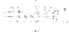
图6(a)、图6(b)、图6(c)和图6(d)是表示传统光电灰尘检测器(见日本专利申请出版物KoKai No.H8-62136(1996))的剖视图、前视图、底视图和背视图。在该检测器上,主体箱101的前面板102和后面板103上分别形成有灰尘通孔102a、103a;灰尘从背面的灰尘通孔103a引入,灰尘通过各个灰尘通孔102a、103a之间的灰尘通道,并且灰尘从前面的灰尘通孔102a被排放出。发光单元104装有发光元件104a、透镜104b和缝104c;发光元件104a发出的光由透镜104b校准然后入射到灰尘通道上。光接收单元105装有光接收元件105a、透镜105b和缝105c;来自灰尘通道的光通过透镜105b凝聚在光接收元件105a上。Fig. 6 (a), Fig. 6 (b), Fig. 6 (c) and Fig. 6 (d) are the sectional views that represent conventional photoelectric dust detector (see Japanese patent application publication KoKai No.H8-62136 (1996)), Front view, bottom view and back view. On this detector, the
这里,在没有灰尘或烟雾通过灰尘通道的情况下,由于几乎所有来自发光单元104的光都会通过灰尘通道并到达光隔离区106,因此光接收单元105接收到的光通量将会非常小。而且,在有灰尘和/或烟雾通过灰尘通道的情况下,由于来自发光单元104的部分光会被灰尘通道中的灰尘和/或烟雾反射并且会入射到光接收单元105上,因此光接收单元105接收到的光通量将会增加。因而,基于光接收单元105的光接收元件105a所接收到的光的输出变化可以检测出通过灰尘通道的灰尘和/或烟雾的存在和/或不存在;和/或基于光接收元件105a的接收光的输出电平可以检测出通过灰尘通道的灰尘和/或烟雾的浓度。Here, if no dust or smoke passes through the dust channel, since almost all the light from the
但是,利用上述传统的光电灰尘检测器,由于主体箱101内设置有灰尘通道(passage route),灰尘和/或烟雾都通过灰尘通道,因此灰尘和/或烟雾有聚集在主体箱101内并且沉积积聚其中的趋势。如果积聚在主体箱101内的沉积物量太大,有时就会出现这种情况:发光单元104发出的部分光被主体箱101内积聚的沉积物以散射的方式反射并入射到光接收单元105上,于是这将导致光接收单元105所接收到的光通量的增加并造成对灰尘和/或烟雾的错误检测。But, utilize above-mentioned conventional photoelectric dust detector, because dust passage (passage route) is arranged in
然而,在上述传统光电检测器中,并没有考虑对积聚在主体箱101内的沉积物进行消除,消除沉积物也是困难的;实际中应用了真空吸尘器等来通过各个小灰尘通孔102a、103a吸走沉积物。However, in the above-mentioned conventional photodetector, no consideration is given to eliminating the deposits accumulated in the
因此本发明的构想源于考虑到上述传统问题,本发明的一个目的是提供一种能容易地消除已经积聚在主体箱内的沉积物的光电灰尘检测器,以及其中安装了这种光电灰尘检测器的空气调节装置。Therefore, the idea of the present invention originates from consideration of the above-mentioned conventional problems, and an object of the present invention is to provide a photoelectric dust detector capable of easily eliminating deposits that have accumulated in the main body box, and in which such a photoelectric dust detector is installed. air conditioning unit.
发明内容Contents of the invention
为了解决上述和/或其他问题,根据本发明的一个或多个实施例的一种光电灰尘检测器,可以包括:一个或多个发光单元、一个或多个光接收单元、一个或多个至少局部地包围光电灰尘检测器的主体箱、一个或多个通孔、以及一个或多个开孔;发光单元用光照射一个或多个灰尘通道,光接收单元接收由通过至少一个灰尘通道或多个灰尘通道的灰尘所反射的光,通孔设置在至少一个主体箱或多个主体箱上以便能将灰尘从外部引入至少一个灰尘通道或多个灰尘通道,开孔设置在至少一个主体箱或多个主体箱上以便能将灰尘从至少一个灰尘通道或多个灰尘通道排放到外部;其中基于从至少一个光接收单元或多个光接收单元输出的接收光来检测灰尘的存在、不存在和/或浓度;并且至少一个开孔或多个开孔大于至少一个通孔或多个通孔。所述光电灰尘检测器还包括:一个或多个检测报告装置,用于检测并报告聚集在该光电灰尘检测器的至少一个主体箱或多个主体箱的内部的一定量或更多的大量灰尘,其中在来自光接收单元的信号电平保持在或高于预定的高的电平期间,所述检测报告装置维持时间的径迹,并且当所述时间超出预定阈值时,所述检测报告装置报告在主体箱内可能已经积聚了大量灰尘。In order to solve the above and/or other problems, a photoelectric dust detector according to one or more embodiments of the present invention may include: one or more light emitting units, one or more light receiving units, one or more at least Partially surround the main body box of the photoelectric dust detector, one or more through holes, and one or more openings; the light-emitting unit illuminates one or more dust passages with light, and the light-receiving unit receives The light reflected by the dust in the dust channel, the through hole is arranged on at least one main body box or a plurality of main body boxes so that dust can be introduced into at least one dust channel or a plurality of dust channels from the outside, and the opening is arranged in at least one main body box or a plurality of dust channels. on a plurality of main body cases so as to be able to discharge dust from at least one dust passage or a plurality of dust passages to the outside; wherein the presence, absence and and/or concentration; and the at least one opening or openings are larger than the at least one through opening or openings. The photoelectric dust detector also includes: one or more detection reporting means for detecting and reporting a certain amount or more of a large amount of dust accumulated inside at least one main body box or a plurality of main body boxes of the photoelectric dust detector , wherein said detection reporting means maintains a track of time while the signal level from the light receiving unit remains at or above a predetermined high level, and when said time exceeds a predetermined threshold, said detection reporting means Reports that a large amount of dust may have accumulated in the main box.
根据以这种方式构成的本发明的实施例,通孔和开孔可以形成在光电灰尘检测器的主体箱上,灰尘通道可以设置在通孔和开孔之间,并且开孔可以大于通孔。设置在排放灰尘的侧面的大开孔可以便于排放灰尘。而且,灰尘较小可能积聚在主体箱内。另外,可以是这种情况,即主体箱内的沉积物可以通过大开孔而容易地除去。此外,当上述一个或多个光电灰尘检测器例如安置在空气调节装置的一个或多个进气口附近时,则至少一个光电检测器或多个检测器的至少一个开孔或多个开孔可以朝向该空气调节装置的内部,并且至少一个光电检测器或多个检测器的至少一个通孔或多个通孔可以朝向该空气调节装置外部。也就是说,通过将光电灰尘检测器的主体箱安置得使小通孔朝向明侧而大开孔朝向暗侧,从而可以减少通过小通孔入射到主体箱的外部光的强度,从而降低了光接收单元检测灰尘时出错的可能性。According to the embodiment of the present invention constituted in this way, the through hole and the opening can be formed on the main body case of the photoelectric dust detector, the dust channel can be provided between the through hole and the opening, and the opening can be larger than the through hole . Large openings provided on the dust discharge side facilitate dust discharge. Also, dust is less likely to accumulate in the main body case. In addition, it may be the case that deposits in the main body tank can be easily removed through the large openings. In addition, when the above-mentioned one or more photoelectric dust detectors are placed near one or more air inlets of the air conditioning device, for example, at least one opening or a plurality of openings of the at least one photoelectric detector or a plurality of detectors The at least one through-hole or through-holes of the at least one photodetector or detectors may be towards the inside of the air-conditioning device, and the at least one through-hole or through-holes of the at least one photodetector or detectors may be towards the outside of the air-conditioning device. That is to say, by arranging the main body case of the photoelectric dust detector so that the small through hole faces the bright side and the large opening faces the dark side, the intensity of external light incident on the main body case through the small through hole can be reduced, thereby reducing the Possibility of errors in the detection of dust by the light receiving unit.
而且,在本发明的一个或多个实施例中,至少一个开孔或多个开孔可以配备至少一个可移动安装的盖。Furthermore, in one or more embodiments of the invention, at least one aperture or apertures may be provided with at least one movably mounted cover.
这种盖可以设置在开孔上,并且当检测灰尘时可以开动该盖以露出开孔。Such a cover can be placed over the opening and can be actuated to reveal the opening when dust is detected.
而且,在本发明的一个或多个实施例中,至少一个盖或多个盖可以设置得能移动距至少一个光路的至少一个距离,该光路从至少一个发光单元或多个单元、灰尘通过的至少一个灰尘通道或多个通道直到至少一个光接收单元或多个单元。Furthermore, in one or more embodiments of the present invention, at least one cover or covers may be arranged to be movable at least a distance from at least one light path from at least one light emitting unit or units, dust passing At least one dust channel or channels up to at least one light receiving unit or units.
作为以这种方式布置盖的结果,来自发光单元的光可以由盖反射从而不入射到光接收单元上,因而消除了这个会导致光接收单元检测灰尘错误的因素。As a result of arranging the cover in this way, the light from the light emitting unit can be reflected by the cover so as not to be incident on the light receiving unit, thus eliminating this factor that would cause the light receiving unit to detect dust erroneously.
另外,本发明的一个或多个实施例可以进一步包括一个或多个检测报告装置,用于检测并报告聚集在光电灰尘检测器的至少一个主体箱或多个机箱内部的一定量或更多的大量灰尘。In addition, one or more embodiments of the present invention may further include one or more detection and reporting devices for detecting and reporting a certain amount or more of Lots of dust.
提供这种检测报告装置可以使得更容易得知什么时候应该除去沉积物。Providing such a detection reporting means can make it easier to know when deposits should be removed.
为了解决上述和/或其他问题,根据本发明的一种空气调节装置,包括上述的一个或多个光电灰尘检测器,其中所述光电灰尘检测器布置在该空气调节装置的一个或多个进气口附近时,至少一个光电检测器或多个检测器的至少一个开孔或多个开孔朝向该空气调节装置里面,而至少一个光电检测器或多个检测器的至少一个通孔或多个通孔朝向该空气调节装置外面。In order to solve the above and/or other problems, an air conditioning device according to the present invention includes the above-mentioned one or more photoelectric dust detectors, wherein the photoelectric dust detectors are arranged in one or more When the air port is near, at least one opening or multiple openings of at least one photoelectric detector or multiple detectors face the inside of the air conditioning device, and at least one through hole or multiple openings of at least one photoelectric detector or multiple detectors A through hole faces the outside of the air conditioning unit.
附图说明Description of drawings
图1(a)、图1(b)、图1(c)和图1(d)是表示根据本发明的光电灰尘检测器的一种实施例的剖视图、前视图、底视图和背视图。1(a), FIG. 1(b), FIG. 1(c) and FIG. 1(d) are a sectional view, a front view, a bottom view and a rear view showing an embodiment of a photoelectric dust detector according to the present invention.
图2是表示根据本实施例的光电灰尘检测器的构造的方块图。FIG. 2 is a block diagram showing the construction of the photoelectric dust detector according to the present embodiment.
图3是表示来自图2中检测器的发光元件的光脉冲的脉冲宽度和周期的示意图。FIG. 3 is a schematic diagram showing the pulse width and period of light pulses from the light emitting elements of the detector in FIG. 2 .
图4是表示图2中的检测器的光接收元件信号电平的曲线图。FIG. 4 is a graph showing a signal level of a light receiving element of the detector in FIG. 2. FIG.
图5是表示图1中的检测器的变更方案的视图。FIG. 5 is a view showing a modification of the detector in FIG. 1 .
图6(a)、图6(b)、图6(c)和图6(d)是表示传统光电灰尘检测器的剖视图、前视图、底视图和背视图。6(a), 6(b), 6(c) and 6(d) are sectional, front, bottom and rear views showing a conventional photoelectric dust detector.
具体实施方式Detailed ways
下面将参照附图详细描述本发明的实施例。Embodiments of the present invention will be described in detail below with reference to the accompanying drawings.
图1(a)、图1(b)、图1(c)和图1(d)是表示根据本发明的光电灰尘检测器的一种实施例的剖视图、前视图、底视图和背视图。1(a), FIG. 1(b), FIG. 1(c) and FIG. 1(d) are a sectional view, a front view, a bottom view and a rear view showing an embodiment of a photoelectric dust detector according to the present invention.
在本实施例的光电灰尘检测器11上,开孔13a形成在主体箱12的前面板13上,通孔14a形成在主体箱12的后面板14上,允许灰尘和/或烟雾通过的灰尘通道设置在后面板14的通孔14a和前面板13的开孔13a之间。通孔14a用于将灰尘和/或烟雾引入灰尘通道。用于将灰尘和/或烟雾从灰尘通道中排放出去的开孔13a充分大于通孔14a。On the
而且,分别安置发光单元15和光接收单元16朝向灰尘通道。多个挡光板17以适当的分布方式安置,从而防止了来自发光单元15的光直接入射到光接收单元16上并且形成了光隔离区18。Also, the light emitting unit 15 and the light receiving unit 16 are disposed toward the dust passage, respectively. A plurality of light baffles 17 are arranged in an appropriate distributed manner, thereby preventing the light from the light emitting unit 15 from being directly incident on the light receiving unit 16 and forming a light isolation region 18 .
发光单元15配备有发光元件15a、透镜15b和缝15c;来自发光元件15a的光由透镜15b校准,校准光束的横断面由于缝15c变窄和/或成形,其后由此存在从那里直接朝向灰尘通道。光接收单元16配备有光接收元件16a、透镜16b和缝16c;来自灰尘通道的光通过缝16c和透镜16b聚集在光接收元件16a上。The light emitting unit 15 is equipped with a
发光单元15的透镜15b和缝15c用于使来自发光元件15a的光集中在灰尘通道上因而避免了这种情况:来自发光元件15a的光可能在主体箱12内被分散和反射,从而使不需要的光入射到光接收单元16上。另外,光接收单元16的透镜16b和缝16c用于使仅由灰尘通道里的灰尘和/或烟雾反射的光由光接收元件16a接收,从而避免了光接收元件16a接收到在主体箱12内反射的不需要的光的情况。The lens 15b and the slit 15c of the light emitting unit 15 are used to concentrate the light from the
在这种光电灰尘检测器11中,如果没有灰尘或烟雾通过灰尘通道,由于来自发光单元15的光将通过灰尘通道并到达光隔离区18,因此光接收单元16接收到的光通量会非常小。而且,如果有灰尘和/或烟雾通过灰尘通道,由于来自发光单元15的一部分光会由灰尘通道里的灰尘和/或烟雾反射并入射到光接收单元16上,因此光接收单元16接收到的光通量将会增加。所以,基于光接收单元16的光接收元件16a的接收光的输出变化可以检测出通过灰尘通道的灰尘和/或烟雾的存在和/或不存在;和/或基于光接收元件16a的接收光输出电平可以检测出通过灰尘通道的灰尘和/或烟雾的浓度。In this
图2是表示根据本实施例的光电灰尘检测器11的构造的方块图。在该光电灰尘检测器11中,微型计算机21通过晶体管22和驱动电路23控制发光元件15a的驱动从而使发光元件15a以图3所示的脉冲方式循环地发光。发光元件15a发出的朝向灰尘通道的光脉冲具有Pw的脉冲宽度并以T的周期发出。当灰尘通道里没有灰尘或烟雾时,光接收元件16a不接收光;但是当灰尘通道里有灰尘和/或烟雾时,光接收元件16a接收由该灰尘和/或烟雾反射的光并输出与接收到的光强度相应的信号。由于来自光接收元件16a的信号很微弱,因此在输入微型计算机21的A/D转换器25之前用三级放大器24将其放大。FIG. 2 is a block diagram showing the configuration of the
注意,没有异议地提供峰值保持电路以保持从各级任何放大器24的下游位置的放大输出。Note that a peak hold circuit is unambiguously provided to hold the amplified output from a location downstream of any
在微型计算机21中,A/D转换器25对光接收元件16a的信号电平(接收光强度)执行A/D转换,并将该信号电平与以前存储在EEPROM(未示出)中的阈值进行比较。如果该信号电平小于阈值,则确定没有灰尘或烟雾在灰尘通道里。但是如果该信号电平大于或等于阈值,则确定有灰尘和/或烟雾在灰尘通道里。而且,如果确定有灰尘和/或烟雾在灰尘通道里时,输出检测信号指示存在灰尘和/或烟雾。替代地或附加地,对应于光接收元件16a的信号电平可以确定灰尘和/或烟雾的浓度,并可以输出检测信号指示灰尘和/或烟雾的浓度。In the
即使碰巧当光电灰尘检测器11的灰尘通道中没有灰尘或烟雾时,来自发光单元15的光仍然会在主体箱12内以散射的方式反射并且光接收单元16仍会接收到少量的光,因此当没有检测到灰尘时光接收元件16a的信号电平(接收光强度)将是恒定值S0,如图4所示。Even when there is no dust or smoke in the dust channel of the
另外,光接收元件16a的信号电平可能会随着与通过灰尘通道的灰尘和/或烟雾的浓度相应的曲线S1所示的那样变化。In addition, the signal level of the
此外,当没有检测到灰尘时信号电平的值S0表示主体箱12内绝对没有沉积灰尘或烟雾的状况,而当没有检测到灰尘时信号电平随着积聚在主体箱12内的沉积物的量的增加而增加。例如,当没有检测到灰尘时信号电平可能增加到值S2的量级上。此时,由于较高的电平S2加到了对应于灰尘和/或烟雾的浓度的曲线S1上,从而导致达到了饱和输出电压,因此不再可以基于信号电平而确定灰尘和/或烟雾的存在、不存在和/或浓度。In addition, the value S0 of the signal level when no dust is detected represents a condition in which dust or smoke is absolutely not deposited in the
因此微型计算机21留下来自光接收元件16a的信号电平延续到维持在值S2附近的这段时间的径迹,并且如果到了该时间例如几十分钟,即如果高信号电平保持了很长一段时间,则这个解释的含义为大量沉积物已经积聚在了主体箱12内,并将输出指示该事实的报告信号,启动蜂鸣器,和/或让LED闪烁。这可以报告已经有大量沉积物积聚在了主体箱12内。Therefore, the
如果来自光接收元件16a的信号电平持续几十分钟小于近似值S2,则这个解释的含义为来自光接收元件16a的信号电平随着灰尘和/或烟雾的浓度的变化而变化。If the signal level from the
这里,由于当报告出主体箱12内已经聚集了大量的沉积物时将不能确定灰尘和/或烟雾的存在、不存在和/或浓度,因此必须将沉积物从主体箱12内移走。主体箱12上的开孔13a充分大于通孔14a。这将可以利用例如尖头棉花的棉拭等来通过开孔13a而容易地拭去和消除主体箱12内的沉积物。而且,由于开孔13a足够大以允许进入对应于发光单元15的透镜15b和光接收单元16的透镜16b的部分,因此可以容易地擦去并消除积聚在各个透镜15b、16b上的沉积物。Here, since the presence, absence and/or concentration of dust and/or smoke cannot be determined when it is reported that a large amount of sediment has accumulated in the
另外,由于侧面提供了排放灰尘和/或烟雾的大开孔13a,因此便于排放灰尘和/或烟雾。而且,还具有减少灰尘和/或烟雾积聚在主体箱12内的趋势的优点。In addition, since the side provides a
而且,通过安置光电灰尘检测器11的主体箱12以使小通孔14a朝向明面并使大开孔13a朝向暗面,可以减少通过小通孔14a入射到主体箱12的外部光的量,从而减少了光接收单元16发生错误检测灰尘和/或烟雾的可能性。And, by placing the
例如,当光电灰尘检测器11布置在空气过滤器、空气洗涤器、空气冷却器和/或其他空气调节装置的进气口附近时,可以安置主体箱12使主体箱12的开孔13a朝向空气调节装置的进气口侧(即里面),并使主体箱12的通孔14a朝向空气调节装置的外面。这样,灰尘和/或烟雾会从主体箱12的通孔14a与空气一起输送并通过开孔13a出去,于是减少了灰尘和/或烟雾积聚在主体箱12内的趋势。另外,小通孔14a朝向空气调节装置明亮的外面,而大开孔13a朝向空气调节装置黑暗的进气口侧(即里面),因此通过小通孔14a入射到主体箱12的外部的光的量减少,这降低了光接收单元16发生错误检测灰尘和/或烟雾的可能性。For example, when the
而且,本发明可以进行许多改变,本发明并不局限于上述实施例。例如,如图5所示,毫无异议,可提供可移动安装在主体箱12的开孔13a上的可滑动的盖31。假如提供它,则开孔13a可以用合适的滑动盖31来适当地揭开。此外,当从主体箱12内消除灰尘和/或烟雾时,盖31可以完全从开孔13a上卸下。Also, the present invention can be modified in many ways, and the present invention is not limited to the above-described embodiments. For example, as shown in FIG. 5, there may be provided a
另外,毫无异议,可对主体箱12上的开孔13a和/或通孔14a的形状、位置、尺寸等等进行适当的修改。In addition, without objection, appropriate modifications can be made to the shape, position, size, etc. of the
如上所述,在本发明的实施例中,通孔和开孔可以形成在光电灰尘检测器的主体箱上,灰尘通道可以设置在通孔和开孔之间,且开孔可以大于通孔。侧面上设置的排放灰尘的大开孔可以便于排放灰尘。而且,灰尘可以有较小的积聚在主体箱内的可能性。此外,可以通过大开孔来容易地消除主体箱内的沉积物。另外,通过安置光电灰尘检测器的主体箱使小通孔朝向明面而大开孔朝向暗面,可以减少通过小通孔入射到主体箱的外部光的量,从而降低了光接收单元发生错误检测灰尘的可能性。As mentioned above, in the embodiment of the present invention, the through hole and the opening can be formed on the main body box of the photoelectric dust detector, the dust channel can be provided between the through hole and the opening, and the opening can be larger than the through hole. The large opening for discharging dust arranged on the side can facilitate dust discharging. Also, dust may have less chance of accumulating in the main body case. Furthermore, deposits in the main body tank can be easily eliminated through the large opening. In addition, by arranging the main box of the photoelectric dust detector so that the small through hole faces the bright side and the large opening faces the dark side, the amount of external light incident on the main box through the small through hole can be reduced, thereby reducing the error of the light receiving unit. Possibility of detecting dust.
注意本发明的光电灰尘检测器不仅对灰尘检测有效而且对检测诸如烟雾等物的存在、不存在和/或浓度同样有效。Note that the photoelectric dust detector of the present invention is effective not only for dust detection but also for detecting the presence, absence and/or concentration of things such as smoke.
在不脱离本发明的精神或基本特征的前提下,本发明可以除了这里所述的形式之外的许多种形式具体。因此,上述实施例和工作实例全都仅仅是说明性的并且不以限制的方式解释。本发明的范围由权利要求指明,它并不局限于说明书中的任何具体实例表达。所有的在权利要求等价范围内的改动和变化都属于本发明的范围内。The present invention may be embodied in many forms other than those set forth herein without departing from the spirit or essential characteristics of the invention. Accordingly, the above-described embodiments and working examples are all illustrative only and not to be construed in a limiting manner. The scope of the present invention is indicated by the claims, and is not limited to any specific expression in the specification. All modifications and changes within the equivalent scope of the claims belong to the scope of the present invention.
Claims (4)
Translated fromChineseApplications Claiming Priority (3)
| Application Number | Priority Date | Filing Date | Title |
|---|---|---|---|
| JP082912/03 | 2003-03-25 | ||
| JP2003082912AJP3917096B2 (en) | 2003-03-25 | 2003-03-25 | Photoelectric dust sensor |
| JP082912/2003 | 2003-03-25 |
Publications (2)
| Publication Number | Publication Date |
|---|---|
| CN1542435A CN1542435A (en) | 2004-11-03 |
| CN1312468Ctrue CN1312468C (en) | 2007-04-25 |
Family
ID=32985022
Family Applications (1)
| Application Number | Title | Priority Date | Filing Date |
|---|---|---|---|
| CNB2004100315671AExpired - Fee RelatedCN1312468C (en) | 2003-03-25 | 2004-03-25 | Optoelectronic dust sensor and air conditioning equipment in which such optoelectronic dust sensor is installed |
Country Status (4)
| Country | Link |
|---|---|
| US (1) | US7038189B2 (en) |
| JP (1) | JP3917096B2 (en) |
| KR (1) | KR20040084739A (en) |
| CN (1) | CN1312468C (en) |
Cited By (2)
| Publication number | Priority date | Publication date | Assignee | Title |
|---|---|---|---|---|
| CN105572003A (en)* | 2014-11-10 | 2016-05-11 | 江苏美的清洁电器股份有限公司 | Control method of dust concentration detection component for dust collector |
| CN108917818A (en)* | 2018-06-29 | 2018-11-30 | 深圳市同泰怡信息技术有限公司 | Machine box for server dust detection method and system |
Families Citing this family (33)
| Publication number | Priority date | Publication date | Assignee | Title |
|---|---|---|---|---|
| TWI245963B (en)* | 2003-12-17 | 2005-12-21 | Benq Corp | Projector and dust-detecting device for filter |
| USD531525S1 (en)* | 2004-11-02 | 2006-11-07 | Sick Ag | Optoelectronic sensor |
| WO2007133235A2 (en)* | 2005-08-08 | 2007-11-22 | Liquidia Technologies, Inc. | Micro and nano-structure metrology |
| JP2007047029A (en)* | 2005-08-10 | 2007-02-22 | Sharp Corp | Dust sensor and air cleaner |
| CA123682S (en)* | 2007-07-10 | 2008-09-22 | Sick Ag | Optoelectronic sensor |
| US8514090B2 (en)* | 2010-11-05 | 2013-08-20 | Oneida Air Systems Inc | Dust level sensor arrangement for dust collection system |
| JP5967525B2 (en)* | 2012-06-13 | 2016-08-10 | パナソニックIpマネジメント株式会社 | Dust detector |
| USD737152S1 (en)* | 2013-12-09 | 2015-08-25 | Hon Hai Precision Industry Co., Ltd. | Image measuring device |
| US9726579B2 (en) | 2014-12-02 | 2017-08-08 | Tsi, Incorporated | System and method of conducting particle monitoring using low cost particle sensors |
| CN106064010A (en)* | 2015-06-29 | 2016-11-02 | 崔子扬 | A kind of air washer filtered for waste gas absorption and double purification mechanism |
| KR101805907B1 (en) | 2016-03-16 | 2018-01-10 | 주식회사 엠넥스 | dust measuring method in air using photographing digital image |
| KR101795238B1 (en) | 2016-04-14 | 2017-11-07 | 현대자동차주식회사 | Dust sensor apparatus for vehicle |
| WO2017217078A1 (en)* | 2016-06-13 | 2017-12-21 | シャープ株式会社 | Photoelectric dust sensor device and air conditioner |
| KR102637410B1 (en)* | 2016-06-16 | 2024-02-16 | 엘지전자 주식회사 | Apparatus and method for measuring dust |
| KR102626632B1 (en)* | 2016-07-20 | 2024-01-18 | 엘지전자 주식회사 | Dust measuring apparatus and mobile terminal for controlling the same |
| KR102791866B1 (en) | 2017-02-28 | 2025-04-07 | 엘지이노텍 주식회사 | Light sensing device and Apparatus for sensing particle |
| KR102568945B1 (en) | 2017-01-02 | 2023-08-22 | 엘지이노텍 주식회사 | Apparatus for sensing particle |
| US11035777B2 (en) | 2017-01-02 | 2021-06-15 | Lg Innotek Co., Ltd. | Light sensing device and particle sensing device |
| KR102644216B1 (en) | 2017-01-10 | 2024-03-05 | 엘지이노텍 주식회사 | Apparatus for sensing particle |
| JP6834507B2 (en)* | 2017-01-17 | 2021-02-24 | 住友電気工業株式会社 | Dust sensor system, cleaning judgment method and cleaning judgment program |
| US20180242480A1 (en)* | 2017-02-17 | 2018-08-23 | Honeywell International Inc. | Shield cover for particle sensor to improve electromagnetic interference performance |
| KR102380173B1 (en) | 2017-04-14 | 2022-03-29 | 엘지이노텍 주식회사 | Apparatus for sensing particle |
| KR102331147B1 (en) | 2017-04-20 | 2021-11-26 | 엘지이노텍 주식회사 | Apparatus for sensing particle |
| KR20190018788A (en) | 2017-08-16 | 2019-02-26 | 주식회사 지티사이언 | Smart Type Lab Table |
| US10788422B2 (en)* | 2017-09-22 | 2020-09-29 | Lg Electronics Inc. | Mobile terminal comprising a dust sensor for sensing scattered light by dust particles and operation method of the same |
| EP3460425B1 (en)* | 2017-09-22 | 2021-04-07 | LG Electronics Inc. | Mobile terminal and operation method of the same |
| US11788942B2 (en)* | 2017-12-15 | 2023-10-17 | Analog Devices, Inc. | Compact optical smoke detector system and apparatus |
| JP2019158442A (en)* | 2018-03-09 | 2019-09-19 | シャープ株式会社 | Display panel inspection system and display panel inspection method |
| RU2709410C1 (en)* | 2018-10-03 | 2019-12-17 | Общество с ограниченной ответственностью "Унискан-Ризерч" | Meter, system and method of measuring mass concentration of dust particles |
| WO2020106036A1 (en) | 2018-11-19 | 2020-05-28 | Samsung Electronics Co., Ltd. | Multimodal dust sensor |
| CN111199628A (en) | 2018-11-20 | 2020-05-26 | 海湾安全技术有限公司 | Smoke detector |
| US12211370B2 (en) | 2018-12-02 | 2025-01-28 | Analog Devices, Inc. | Fire detection system |
| US11796445B2 (en) | 2019-05-15 | 2023-10-24 | Analog Devices, Inc. | Optical improvements to compact smoke detectors, systems and apparatus |
Citations (7)
| Publication number | Priority date | Publication date | Assignee | Title |
|---|---|---|---|---|
| GB840768A (en)* | 1956-05-15 | 1960-07-13 | Kelvin & Hughes Ltd | Methods of and apparatus for the measurement or indication of smoke density |
| US3985453A (en)* | 1974-07-19 | 1976-10-12 | Matsushita Electric Works, Ltd. | Light scattering type smoke detector |
| CN85106166A (en)* | 1985-08-15 | 1987-03-04 | 报知机株式会社 | Scattered Light Smoke Detector |
| US4672217A (en)* | 1985-04-05 | 1987-06-09 | General Signal Corporation | Easily cleaned photoelectric smoke detector |
| US4748336A (en)* | 1985-05-01 | 1988-05-31 | Nippondenso Co., Ltd. | Optical dust detector assembly for use in an automotive vehicle |
| CN2096067U (en)* | 1991-04-19 | 1992-02-12 | 北京利达防火保安设备有限公司 | Photoelectric smoke sensitive probe photo sensitive room |
| JPH0862136A (en)* | 1994-08-24 | 1996-03-08 | Sharp Corp | Photoelectric smoke detector |
Family Cites Families (3)
| Publication number | Priority date | Publication date | Assignee | Title |
|---|---|---|---|---|
| US4906978A (en)* | 1986-12-24 | 1990-03-06 | Cerberus Ag | Optical smoke detector |
| KR930003937Y1 (en)* | 1991-08-14 | 1993-06-25 | 주식회사 금성사 | Suction suction detection device of vacuum cleaner |
| JP4658452B2 (en)* | 2003-02-07 | 2011-03-23 | オリンパス株式会社 | Optical encoder |
- 2003
- 2003-03-25JPJP2003082912Apatent/JP3917096B2/ennot_activeExpired - Fee Related
- 2004
- 2004-03-16USUS10/801,005patent/US7038189B2/ennot_activeExpired - Fee Related
- 2004-03-24KRKR1020040019839Apatent/KR20040084739A/ennot_activeCeased
- 2004-03-25CNCNB2004100315671Apatent/CN1312468C/ennot_activeExpired - Fee Related
Patent Citations (7)
| Publication number | Priority date | Publication date | Assignee | Title |
|---|---|---|---|---|
| GB840768A (en)* | 1956-05-15 | 1960-07-13 | Kelvin & Hughes Ltd | Methods of and apparatus for the measurement or indication of smoke density |
| US3985453A (en)* | 1974-07-19 | 1976-10-12 | Matsushita Electric Works, Ltd. | Light scattering type smoke detector |
| US4672217A (en)* | 1985-04-05 | 1987-06-09 | General Signal Corporation | Easily cleaned photoelectric smoke detector |
| US4748336A (en)* | 1985-05-01 | 1988-05-31 | Nippondenso Co., Ltd. | Optical dust detector assembly for use in an automotive vehicle |
| CN85106166A (en)* | 1985-08-15 | 1987-03-04 | 报知机株式会社 | Scattered Light Smoke Detector |
| CN2096067U (en)* | 1991-04-19 | 1992-02-12 | 北京利达防火保安设备有限公司 | Photoelectric smoke sensitive probe photo sensitive room |
| JPH0862136A (en)* | 1994-08-24 | 1996-03-08 | Sharp Corp | Photoelectric smoke detector |
Cited By (3)
| Publication number | Priority date | Publication date | Assignee | Title |
|---|---|---|---|---|
| CN105572003A (en)* | 2014-11-10 | 2016-05-11 | 江苏美的清洁电器股份有限公司 | Control method of dust concentration detection component for dust collector |
| CN105572003B (en)* | 2014-11-10 | 2018-10-19 | 江苏美的清洁电器股份有限公司 | The control method of dust concentration detection components for dust catcher |
| CN108917818A (en)* | 2018-06-29 | 2018-11-30 | 深圳市同泰怡信息技术有限公司 | Machine box for server dust detection method and system |
Also Published As
| Publication number | Publication date |
|---|---|
| US20040188598A1 (en) | 2004-09-30 |
| JP2004294082A (en) | 2004-10-21 |
| US7038189B2 (en) | 2006-05-02 |
| JP3917096B2 (en) | 2007-05-23 |
| KR20040084739A (en) | 2004-10-06 |
| CN1542435A (en) | 2004-11-03 |
Similar Documents
| Publication | Publication Date | Title |
|---|---|---|
| CN1312468C (en) | Optoelectronic dust sensor and air conditioning equipment in which such optoelectronic dust sensor is installed | |
| CN1898551A (en) | Method for evaluating a scattered light signal and a scattered light detector for realizing the method | |
| US7659980B1 (en) | Nephelometric turbidity sensor device | |
| US20200011779A1 (en) | Highly integrated optical particle counter (opc) | |
| CN101261225B (en) | Smoke detector | |
| EP0638885B1 (en) | Fire detecting apparatus | |
| KR101905275B1 (en) | Particle sensor and electronic apparatus equipped with the same | |
| US20100039645A1 (en) | Method and system for particle detection | |
| JP5967525B2 (en) | Dust detector | |
| CN110231261B (en) | Particulate matter concentration detection device | |
| KR20170097391A (en) | Sensor device for sensing fine dust | |
| JP2017116417A (en) | Photoelectric dust sensor and air conditioner | |
| WO2008109933A1 (en) | Particle detection apparatus | |
| JP3012271B2 (en) | air purifier | |
| JP4995608B2 (en) | smoke detector | |
| JP2008039735A (en) | Particle measuring device | |
| KR20190123964A (en) | Dust sensor | |
| JP3107277B2 (en) | air purifier | |
| KR20180113341A (en) | Apparatus for sensing particle | |
| JP2010231613A (en) | Fire detector | |
| US11885726B2 (en) | Particulate matter sensor | |
| JPH08263767A (en) | Particulate detecting sensor | |
| JP2007047029A (en) | Dust sensor and air cleaner | |
| JPH05126717A (en) | Dust detection device | |
| JP6483907B1 (en) | Foreign object detection device |
Legal Events
| Date | Code | Title | Description |
|---|---|---|---|
| C06 | Publication | ||
| PB01 | Publication | ||
| C10 | Entry into substantive examination | ||
| SE01 | Entry into force of request for substantive examination | ||
| C14 | Grant of patent or utility model | ||
| GR01 | Patent grant | ||
| C17 | Cessation of patent right | ||
| CF01 | Termination of patent right due to non-payment of annual fee | Granted publication date:20070425 |