CN1311153A - Elevator control device - Google Patents
Elevator control deviceDownload PDFInfo
- Publication number
- CN1311153A CN1311153ACN01108362ACN01108362ACN1311153ACN 1311153 ACN1311153 ACN 1311153ACN 01108362 ACN01108362 ACN 01108362ACN 01108362 ACN01108362 ACN 01108362ACN 1311153 ACN1311153 ACN 1311153A
- Authority
- CN
- China
- Prior art keywords
- charging
- current
- discharge
- charge
- voltage
- Prior art date
- Legal status (The legal status is an assumption and is not a legal conclusion. Google has not performed a legal analysis and makes no representation as to the accuracy of the status listed.)
- Granted
Links
Images


Classifications
- B—PERFORMING OPERATIONS; TRANSPORTING
- B66—HOISTING; LIFTING; HAULING
- B66B—ELEVATORS; ESCALATORS OR MOVING WALKWAYS
- B66B1/00—Control systems of elevators in general
- B—PERFORMING OPERATIONS; TRANSPORTING
- B66—HOISTING; LIFTING; HAULING
- B66B—ELEVATORS; ESCALATORS OR MOVING WALKWAYS
- B66B1/00—Control systems of elevators in general
- B66B1/24—Control systems with regulation, i.e. with retroactive action, for influencing travelling speed, acceleration, or deceleration
- B66B1/28—Control systems with regulation, i.e. with retroactive action, for influencing travelling speed, acceleration, or deceleration electrical
- B66B1/30—Control systems with regulation, i.e. with retroactive action, for influencing travelling speed, acceleration, or deceleration electrical effective on driving gear, e.g. acting on power electronics, on inverter or rectifier controlled motor
Landscapes
- Engineering & Computer Science (AREA)
- Automation & Control Theory (AREA)
- Elevator Control (AREA)
- Charge And Discharge Circuits For Batteries Or The Like (AREA)
Abstract
Translated fromChineseDescription
Translated fromChinese本发明涉及使用蓄电池的节能型电梯控制装置。The invention relates to an energy-saving elevator control device using a storage battery.
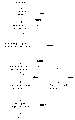
图20是以往使用蓄电池并控制电梯的控制装置基本构成图。Fig. 20 is a diagram showing the basic configuration of a conventional control device for controlling an elevator using a storage battery.
在图20中,1表示三相交流电源,2表示将由三相交流电源1输出的交流电变换为直流电的由二极管等构成的逆变器,由逆变器2所变换后的直流电供给直流母线3。4是由后述速度控制装置控制的进行电梯的速度位置控制的逆变器,它将通过直流母线3供给的直流电变换为要求的可变电压可变频率的交流电后供给交流电动机5,由此驱动与交流电动机5直接连接的电梯的提升机6,这样,卷绕在提升机6上的钢丝7控制连接其两端的电梯轿厢8及对重9的升降而将电梯轿厢8内的乘客运送到规定的楼层。In Fig. 20, 1 denotes a three-phase AC power supply, and 2 denotes an inverter composed of diodes for converting the AC power output from the three-phase
这里,电梯轿厢8及对重9的重量设计为当电梯轿厢8内乘有一半定员时两者重量几乎相等。即,无占空比升降电梯轿厢8时,电梯轿厢8下降时进行动力运行,上升时进行再生运行。相反,乘有定员降电梯轿厢8时,下降时进行再生运行,上升时进行动力运行。Here, the weight of the
10是由微型计算机等构成的电梯控制电路,它进行电梯整体的管理与控制。11表示设置于直流母线3之间、当电梯再生运行时积蓄电能而在动力运行时与逆变器2同时将积蓄的功率供给逆变器4的蓄电装置,它是由蓄电池12以及控制该蓄电池12充放电的DC-DC逆变器13构成。10 is an elevator control circuit composed of a microcomputer, etc., which manages and controls the elevator as a whole. 11 represents an electric storage device arranged between the
这里,DC-DC逆变器13具备降压型斩波电路以及升压型斩波电路,该降压型斩波电路由电抗器13a、与该电抗器串联的充电电流控制门13b、与下述放电电流控制门13d反向并联的二极管13c构成,该升压型斩波电路由电抗器13a、与该电抗器13a串联的放电电流控制门13d以及与上述充电电流控制门13b反向并联的二极管13e构成,充电电流控制门13b以及放电电流控制门13d是由充放电控制电路15根据检测蓄电装置11充放电状态的充放电状态检测器14输出的检测值以及电压检测器18输出的检测值而进行控制。又,对于以往示例中的充放电状态检测器14,是使用设置于蓄电池12与DC-DC逆变器13之间的电流检测器。Here, the DC-
16与17是设置于直流母线3之间的再生电流控制门与再生电阻,18是检测直流母线3电压的电压检测器,19表示根据下述速度控制电路输出的再生控制指令进行工作的再生控制电路,再生电流控制门16在再生运行条件下,当电压检测器17检测到的电压大于规定值时,根据再生控制电路19的控制进行闭合脉冲宽度的控制,再生功率通过电流流过再生电阻而变换为热能消耗。16 and 17 are regenerative current control gates and regenerative resistors arranged between the
20是与提升机6直接连接的编码器,21是速度控制电路,该速度控制电路根据电梯控制电路10发出的指令,按照速度指令以及来自编码器22的速度反馈输出来控制逆变器4的输出电压及输出频率,而由此控制电梯的位置及速度。20 is an encoder directly connected to the
下面,对于上述构成的动作进行说明。Next, the operation of the above configuration will be described.
当电梯动力运行时,三相交流电源1以及蓄电装置11两者向逆变器4供电。蓄电装置11由蓄电池12以及DC-DC逆变器13构成,并且受到充放电控制电路15控制。一般为了构成小型、价廉的装置,要减少蓄电池12的个数,蓄电池12的输出电压也小于直流母线3的电压。而且,直流母线3的电压大致被控制在将三相交流电源1进行整流的电压附近。因此,蓄电池12充电时必须降低直流母线3的母线电压,放电时必须上升直流母线3的母线电压,为此采用DC-DC逆变器13。由充放电控制电路15控制该DC-DC逆变器13的充放电电流控制门13b以及放电电流控制门13d。When the elevator is running under power, both the three-phase
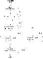
图21与图22是表示充放电控制电路15在放电时与充电时的控制流程图。21 and 22 are flow charts showing the control flow of the charging and discharging
首先,对于图21所示的放电时的控制进行说明。First, the control at the time of discharge shown in FIG. 21 will be described.
作为控制系统,在电压控制中构成电流控制局部环路等,可以进行更加稳定的控制,但这里,为了简化起见,以母线电压控制的方式进行说明。As a control system, more stable control can be achieved by constructing a current control partial loop in the voltage control, but here, for the sake of simplicity, the bus voltage control will be described.
首先,由电压检测器17检测直流母线3的母线电压(步骤S11)。充放电控制电路15将该检测电压与要求的电压设定值进行比较,判定检测电压是否超过电压设定值(步骤S12),当检测电压没有超过设定值时,则接着判定由充放电状态检测器14检测到的蓄电池12的放电电流值是否超过规定值(步骤S13)。First, the bus voltage of the
根据上述判定,当检测电压超过设定值时,或者检测电压没有超过设定值而蓄电池12的放电电流检测值超过设定值时,为了减小放电电流控制门13d闭合脉冲宽度,从当前闭合时间减去调整时间DT而求得新的门闭合时间(步骤S14)。According to the above judgment, when the detection voltage exceeds the set value, or when the detection voltage does not exceed the set value but the discharge current detection value of the
另外,在上述步骤S13中,当判定电流检测器14检测出的蓄电池12的放电电流检测值没有超过规定值时,为了增加放电电流控制门13d的闭合脉冲宽度,在当前的闭合时间上加上调整时间DT而求得新的门闭合时间(步骤S15)。根据如此求得的门闭合时间,控制放电电流控制门13d的闭合,同时将求得的门闭合时间作为当前闭合时间而存储在内装存储器中(步骤S16)。In addition, in the above-mentioned step S13, when it is determined that the discharge current detection value of the
由此,通过增加放电电流控制门13d的闭合脉冲宽度,使得更加多的电流从蓄电池12流出,结果是在增大供电功率的同时也由于供给功率使直流母线3的母线电压上升。考虑到在动力运行时,对电梯必须供给功率,此功率由上述蓄电池12的放电以及三相交流电源1的供电来提供。当进行控制使得母线电压比利用三相交流电源1供电的逆变器2的输出电压高时,所有的功率由蓄电池12供给。然而,为了构成价廉的蓄电装置11,则不应由蓄电池12来供给所有的功率,而设计为按照适当的比例由蓄电池12及三相交流电源1进行供电。Thus, by increasing the closing pulse width of the discharge
即,在图21中,将放电电流的检测值与相当于供给分担的电流(规定值)进行比较,当没有超过规定值,则增加放电电流控制门13d的闭合脉冲宽度,进一步增大供给量,而当放电电流的检测值超过规定值时,缩短放电电流控制门13d的闭合脉冲宽度来限制功率供给。这样,在逆变器4所必要的功率内限制了由蓄电池12供给的份额,因此,直流母线3的母线电压降低,结果由逆变器2开始供给功率。这些由于是在非常短的时间内进行的,实际上为了供给电梯必要的功率,可以将其稳定在适当的母线电压,由蓄电池12以及三相交流电源1按照所要求的比例进行供电。That is, in FIG. 21, the detection value of the discharge current is compared with the current (predetermined value) corresponding to the supply share, and when it does not exceed the specified value, the closing pulse width of the discharge
其次,对于图22所示充电时的控制进行说明。Next, the control at the time of charging shown in FIG. 22 will be described.
当交流电动机5进行功率再生时,直流母线3的母线电压由于该再生功率而上升。当该电压比逆变器2的输出电压高时,停止由三相交流电源1供电。当不存在蓄电装置11的情况下,如持续这种状态则直流母线3的电压上升,因此检测直流母线3母线电压的电压检测器17的检测电压值当达到某规定电压时,则再生控制电路19进行动作,闭合再生电流控制门16。由此,电流流向再生电阻17,消耗再生功率,同时因电磁制动效果使得电梯减速。但是,当存在蓄电装置11的情况下,在小于规定电压时,通过充放电控制电路15的控制,使得此功率对蓄电装置11进行充电。When the
即,如图10所示,当电压检测器17检测到的直流母线3的母线电压检测值超过规定电压时,充放电控制电路15检测到是再生状态,通过增加充电电流控制门13b的闭合脉冲宽度而来增大向蓄电池12的充电电流(步骤S21->步骤S22->步骤S23)。不久若电梯产生的再生功率变小,则直流母线3的电压随之降低,由于电压检测器17的检测值没有超过规定电压,因此进行控制使得充电电流控制门13b的闭合脉冲宽度变小,充电功率也变小(步骤S21->S22->S24)。That is, as shown in FIG. 10, when the bus voltage detection value of the
如此,通过监视直流母线3的母线电压来控制充电功率,将母线电压控制在适当的范围中而进行充电。又,以往是通过积蓄和再利用原来消耗掉的再生功率来实现节能的。当充电装置因某种原因而没有消耗功率时,作为后备的措施是使得上述再生控制电路19进行动作,通过电阻来消耗再生功率而使得电梯适当减速。根据电梯容量等不同,再生功率也不同,对于住宅用一般电梯,再生功率为2KVA左右,在减速的最大值时再生功率为4KVA左右。In this way, charging power is controlled by monitoring the bus voltage of the
再生控制电路19监视直流母线3的电压,如超过规定电压时,则为了通过再生电阻17将上述功率消耗掉,利用再生控制电路19来控制再生电流控制门16的闭合脉冲宽度,由此使得再生功率产生的电流流入再生电阻17。这种脉冲宽度控制的方式虽有多种,为简单起见,可采用下式进行。现在,设使得再生电流控制门16开始闭合的直流母线3的电压为VR,则由于再生电阻17的值是已知的,因此当闭合电路时,就能够简单地计算电流IR,并且由于要消耗的最大功率已知,将该功率(VA)作为WR,则只要产生WR/(VR×IR)占空比的闭合脉冲即可,这可以在监视直流母线电压的同时进行。但是,最终的目的也是为了通过再生电阻17来消耗再生功率。The
然而,对于上述以往的电梯控制装置,蓄电装置11必须装有大容量的蓄电池12,该蓄电池12在蓄电装置11的温度、充电程度、即以蓄电装置11的满充电状态为基准而将充放电电流与充放电电压的乘积以容量进行归一化且累积的值即SOC(:stateofcharge,充电状态)等所有条件下,能够将再生功率进行充电。因此,这就需要高价的、大容量蓄电装置11。However, for the above-mentioned conventional elevator control device, the power storage device 11 must be equipped with a large-
本发明为了解决上述问题,目的是提供一种电梯控制装置,它不影响充电的节省能源的效果,并且使用低容量低价格的蓄电装置而能对蓄电装置进行稳定的充放电控制。In order to solve the above problems, the present invention aims to provide an elevator control device that does not affect the energy-saving effect of charging, and uses a low-capacity and low-cost power storage device to perform stable charge and discharge control on the power storage device.
本发明的电梯控制装置,其特点在于,它具备:将来自交流电源的交流电进行整流变换为直流电的变换器;将上述变换器输出的直流电变换为可变电压可变频率的交流电而驱动电动机使电梯运行的逆变器;设置于上述变换器与上述逆变器间的直流母线之间并且在电梯再生运行时积蓄来自直流母线的直流电、在动力运行时将积蓄的直流电供给直流母线的蓄电装置;控制上述蓄电装置与上述直流母线之间进行充放电的充放电控制装置;检测上述直流母线的母线电压的母线电压检测手段;检测上述蓄电装置的充放电状态的充放电状态检测手段。并且,上述充放电控制手段根据来自上述母线电压检测手段的检测值以及来自上述充放电状态检测手段的检测值而控制上述蓄电装置的充放电。The elevator control device of the present invention is characterized in that it has: a converter for rectifying and converting the alternating current from the alternating current power source into direct current; converting the direct current output by the converter into alternating current of variable voltage and variable frequency to drive the motor to Inverter for elevator operation; it is installed between the above-mentioned converter and the DC bus between the above-mentioned inverter and stores the DC power from the DC bus during the regenerative operation of the elevator, and supplies the stored DC power to the DC bus during power running. device; a charging and discharging control device for controlling charging and discharging between the above-mentioned power storage device and the above-mentioned DC bus; a bus voltage detection means for detecting the bus voltage of the above-mentioned DC bus; a charging and discharging state detection means for detecting the charging and discharging state of the above-mentioned power storage device . Furthermore, the charge and discharge control means controls charge and discharge of the power storage device based on the detection value from the bus voltage detection means and the detection value from the charge and discharge state detection means.
又,上述充放电控制手段具备对应于温度设定限定充电电流的工作表,根据来自上述充放电状态检测手段的温度检测值,从上述工作表中求得温度检测值所对应的限定充电电流,根据来自上述充放电状态检测手段的充放电电流检测值与限定充电电流的比较结果,控制对上述蓄电装置的充电电流。Also, the above-mentioned charging and discharging control means has a working table corresponding to the temperature setting limit charging current, and according to the temperature detection value from the above-mentioned charging and discharging state detecting means, obtain the limited charging current corresponding to the temperature detection value from the above working table, A charge current to the power storage device is controlled based on a comparison result of a charge and discharge current detection value from the charge and discharge state detection means and a limited charge current.
又,上述充放电控制手段具备多个工作表,上述工作表是以上述蓄电装置的满充电状态为基准,与将充放电电流及充放电电压的乘积以容量进行归一化并累积的值即充电程度相对应,选择与上述充电程度相对应的工作表。In addition, the charge and discharge control means includes a plurality of work tables, and the work table is a value obtained by normalizing the product of the charge and discharge current and the charge and discharge voltage by the capacity based on the fully charged state of the power storage device and accumulating That is, corresponding to the charging degree, select the worksheet corresponding to the above charging degree.
又,上述充放电控制手段具备工作表,上述工作表以上述蓄电装置的满充电状态为基准,相对于将充放电电流及充放电电压的乘积以容量进行归一化并累积的值即充电程度设定限定充电电流,根据来自上述充放电状态检测手段其检测值的充放电程度值求出所对应限定充电电流,根据充电电流的检测值与限定充电电流的比较结果,控制对上述蓄电装置的充电电流。In addition, the above-mentioned charge and discharge control means includes a work table, and the above work table is based on the fully charged state of the above-mentioned power storage device, and the charge-discharge current and the charge-discharge voltage are normalized and accumulated by the capacity. Set the limited charging current according to the degree, calculate the corresponding limited charging current according to the charging and discharging degree value from the detected value of the above-mentioned charging and discharging state detection means, and control the above-mentioned storage battery according to the comparison result between the detected value of the charging current and the limited charging current. device charging current.
又,上述充放电控制手段根据来自上述充放电状态检测手段的充电电流检测值与最大充电电流设定值的比较结果,控制对上述蓄电装置的充电电流。Furthermore, the charging/discharging control means controls the charging current to the power storage device based on a comparison result of the charging current detection value from the charging/discharging state detecting means and a maximum charging current setting value.
又,上述充放电控制手段具备相对于充电电流设定最大充电电压的工作表,求出来自上述充放电状态检测手段的充电电流检测值所对应的最大充电电压设定值,根据充电电压检测值与最大充电电压设定值的比较结果控制对上述蓄电装置的充电电流。Also, the charging and discharging control means has a work table for setting the maximum charging voltage with respect to the charging current, obtains the maximum charging voltage setting value corresponding to the charging current detection value from the charging and discharging state detection means, and calculates the maximum charging voltage setting value based on the charging voltage detection value. The result of the comparison with the maximum charging voltage setting value controls the charging current to the power storage device.
又,上述电梯控制装置还具备通过控制上述逆变器的输出电压输出频率来控制电梯速度的速度控制手段,上述充放电控制手段根据来自上述母线电压检测手段的检测值、上述充放电状态检测手段的检测值以及来自上述速度控制手段的速度指令,控制上述蓄电装置的放电电流。Also, the above-mentioned elevator control device is further provided with a speed control means for controlling the speed of the elevator by controlling the output voltage output frequency of the above-mentioned inverter. The detected value and the speed command from the speed control means control the discharge current of the power storage device.
又,上述充放电控制手段具备相对于温度设定的限定放电电流的工作表,求出来自上述充放电状态检测手段的温度检测值所对应的限定放电电流,并且根据放电电流检测值与限定放电电流的比较结果,控制上述蓄电装置的放电电流。Also, the above-mentioned charging and discharging control means is provided with a working table of the limited discharge current set with respect to the temperature, obtains the limited discharge current corresponding to the temperature detection value from the above-mentioned charge and discharge state detection means, and The result of the current comparison controls the discharge current of the power storage device.
又,上述充放电控制手段具备以上述蓄电装置的满充电状态为基准而与将充放电电流与充放电电压的乘积以容量进行归一化并累积的值即充电程度相对应的多个工作表,选择根据来自上述充放电状态检测手段其检测值的充放电程度所对应的工作表。In addition, the charge and discharge control means includes a plurality of operations corresponding to a value obtained by normalizing and accumulating a product of charge and discharge current and charge and discharge voltage by a capacity based on a fully charged state of the electric storage device, that is, a charge level. Table, select the worksheet corresponding to the degree of charge and discharge according to the detection value from the above-mentioned charge and discharge state detection means.
又,上述充放电控制手段具备以上述蓄电装置的满充电状态为基准而与将充放电电流与充放电电压的乘积以容量进行归一化并累积的值即充电程度所对应的设定限定放电电流的工作表,根据来自上述充放电状态检测手段其检测值求出充电程度值所对应的限定放电电流,根据放电电流的检测值与限定放电电流的比较结果,控制上述蓄电装置的放电电流。In addition, the charging and discharging control means includes a setting limit corresponding to a value obtained by normalizing and accumulating a product of charging and discharging current and charging and discharging voltage by a capacity based on a fully charged state of the power storage device, that is, a charging degree. The working table of the discharge current, according to the detection value from the above-mentioned charge-discharge state detection means, obtains the limited discharge current corresponding to the charging degree value, and controls the discharge of the above-mentioned electric storage device according to the comparison result of the detection value of the discharge current and the limited discharge current. current.
又,上述充放电控制手段具备相对于放电电流设定最大放电电压的工作表,求出来自上述充放电状态检测手段的放电电流检测值所对应的最大放电电压的设定值,根据放电电压检测值与最大放电电压设定值的比较结果,来控制蓄电装置的放电电流。In addition, the above-mentioned charging and discharging control means has a working table for setting the maximum discharge voltage with respect to the discharge current, obtains the set value of the maximum discharge voltage corresponding to the discharge current detection value from the above-mentioned charge and discharge state detection means, and detects the maximum discharge voltage based on the discharge voltage. Value and the maximum discharge voltage set value comparison results to control the discharge current of the storage device.
图1是表示本发明的电梯控制装置的构成框图。Fig. 1 is a block diagram showing the configuration of an elevator control device according to the present invention.
图2是本发明实施形态1中充放电控制电路15A所具有的工作表的说明图。Fig. 2 is an explanatory diagram of an operation table included in charge and
图3是表示本发明实施形态1中充放电控制电路15A的充电控制内容流程图。Fig. 3 is a flow chart showing the charge control content of charge and
图4是本发明实施形态2中充放电控制电路15A所具有的多个工作表的说明图。Fig. 4 is an explanatory diagram of a plurality of work tables included in the charge and
图5是表示本发明实施形态2中充放电控制电路15A的充电控制内容流程图。Fig. 5 is a flow chart showing the charge control content of charge and
图6是本发明实施形态3中充放电控制电路15A所具有的工作表的说明图。Fig. 6 is an explanatory diagram of an operation table included in charge and
图7是表示本发明实施形态3中充放电控制电路15A的充电控制内容流程图。Fig. 7 is a flow chart showing the charge control content of charge and
图8是表示本发明实施形态4中充放电控制电路15A的充电控制内容流程图。Fig. 8 is a flow chart showing the charge control content of charge and
图9是本发明实施形态5中充放电控制电路15A所具有的工作表的说明图。Fig. 9 is an explanatory diagram of an operation table included in the charging and discharging
图10是表示本发明实施形态5中充放电控制电路15A的充电控制内容流程图。Fig. 10 is a flow chart showing the charge control content of charge and
图11是表示本发明实施形态6中充放电控制电路15A的充电控制内容流程图。Fig. 11 is a flow chart showing the charge control content of charge and
图12是本发明实施形态7中充放电控制电路15A所具有的工作表的说明图。Fig. 12 is an explanatory diagram of an operation table included in the charge and
图13是表示本发明实施形态7中充放电控制电路15A的放电控制内容流程图。Fig. 13 is a flow chart showing the content of discharge control by charge and
图14是本发明实施形态8中充放电控制电路15A所具有的工作表的说明图。Fig. 14 is an explanatory diagram of an operation table included in charge and
图15是表示本发明实施形态8中充放电控制电路15A的放电控制内容流程图。Fig. 15 is a flow chart showing discharge control contents of charge and
图16是本发明实施形态9中充放电控制电路15A所具有的工作表的说明图。Fig. 16 is an explanatory diagram of an operation table included in charge and
图17是表示本发明实施形态9中充放电控制电路15A的放电控制内容流程图。Fig. 17 is a flow chart showing the content of discharge control by charge and
图18是本发明实施形态10中充放电控制电路15A所具有的工作表的说明图。Fig. 18 is an explanatory diagram of an operation table included in charge and
图19是表示本发明实施形态10中充放电控制电路15A的放电控制内容流程图。Fig. 19 is a flow chart showing the content of discharge control by charge and
图20是表示以往示例的电梯控制装置的构成框图。Fig. 20 is a block diagram showing the configuration of a conventional elevator control device.
图21是表示图20所示的充放电控制电路15放电时的控制流程图。FIG. 21 is a flow chart showing the control during discharge by the charging and discharging
图22是表示图20所示的充放电控制电路15充电时的控制流程图。FIG. 22 is a flow chart showing control during charging by the charging and discharging
1三相交流电源1 three-phase AC power supply
2变换器2 converters
3直流母线3 DC bus
4逆变器4 inverters
5交流电动机5 AC motor
6提升机6 Hoists
7绳索7 ropes
8电梯轿厢8 elevator cars
9对重9 counterweights
10电梯控制电路10 elevator control circuit
11蓄电装置11 power storage device
12蓄电池12 batteries
13DC-DC变换器13DC-DC converter
14,14A充放电状态检测装置14,14A charge and discharge state detection device
15,15A充放电控制电路15,15A charge and discharge control circuit
16再生电流控制门16 Regenerative current control gate
17再生电阻17 regenerative resistor
18电压检测器18 voltage detector
19再生控制电路19 regeneration control circuit
20编码器20 encoders
21速度控制电路21 speed control circuit
实施形态Implementation form
在本发明中,为了确保节能的效果,向蓄电装置的充电要尽可能多地接受再生功率,而为了确保充电能力及电池寿命,要控制不进行过充电。In the present invention, in order to ensure the energy-saving effect, the power storage device is charged with as much regenerative power as possible, and in order to ensure the charging capacity and battery life, it is controlled not to perform overcharging.
即,本发明提供一种电梯,它具备通过检测母线电压以及蓄电装置的充放电状态并根据检测值进行充放电控制从而延长电池寿命的蓄电装置。That is, the present invention provides an elevator including an electric storage device that detects a bus voltage and a state of charge and discharge of the electric storage device, and performs charge and discharge control based on the detected values to extend the life of the battery.
蓄电装置中使用的蓄电池特性因铅电池、镍氢电池等电池种类而有所不同,一般情况下,在温度比通常低或者比通常高的状态,充电的情况较差,当充电程度高(接近满充电状态),当然很难接受充电。在这样很难接受充电的状态下,当用很大的电流要进行充电时,则不仅内阻增大即不仅产生电池发热与充电电压上升,而且使得此后的充电性能劣化。因此,必须控制使得尽量避免过充电。The characteristics of the battery used in the power storage device vary depending on the type of battery such as lead battery and nickel-metal hydride battery. Generally, when the temperature is lower or higher than usual, the charging situation is poor. When the charging degree is high ( close to full charge state), of course it is difficult to accept the charge. In such a state that it is difficult to accept charging, when charging with a large current, not only the internal resistance increases, that is, not only the battery generates heat and the charging voltage rises, but also the subsequent charging performance deteriorates. Therefore, it is necessary to control so as to avoid overcharging as much as possible.
图1是表示本发明的电梯控制装置的构成框图。与图20所示的以往示例相同的部分使用相同的符号并且省略对它们的说明。作为新的符号,14A与15A表示本发明的充放电状态检测装置与充放电控制电路,充放电状态检测装置14A具备检测蓄电装置11的充放电电流、充放电电压及温度的各种检测器,并将这些检测值以及充电程度SOC输出到充放电控制电路15A。充放电控制电路15A根据来自电压检测器18的母线电压检测值、来自上述充放电状态检测装置14的检测值以及来自速度控制电路21的速度指令,控制蓄电装置11的充放电。Fig. 1 is a block diagram showing the configuration of an elevator control device according to the present invention. The same symbols are used for the same parts as those in the conventional example shown in FIG. 20 and their descriptions are omitted. As new symbols, 14A and 15A represent the charge and discharge state detection device and the charge and discharge control circuit of the present invention, and the charge and discharge
以下,对于具体的实施形态进行说明。Hereinafter, specific embodiments will be described.
实施形态1
在实施形态1中,充放电控制电路具备如图2所示的对应于蓄电装置11的蓄电池12的温度设定限定充电电流的工作表T1,从充放电状态检测装置14A输入蓄电装置11的蓄电池12的温度检测值,并且从上述工作表T1中求得输入的温度检测值所对应的限定充电电流,再根据来自上述充放电状态检测装置14A的充电电流检测值与限定充电电流的比较结果,来控制对蓄电装置11的充电电流。In
其次,参照图3的流程图对于本实施形态1中充放电控制电路15A的控制进行说明。Next, the control of charge and
充放电控制电路15A首先根据来自电压检测器18的检测值来确认直流母线3的电压,根据该母线电压来确认电梯为再生状态还是动力状态,判定母线电压是否超过规定值(步骤S101,S102)。若母线电压没有超过规定值,则因处在动力状态而不进行充电,控制蓄电装置11的DC-DC变换器13的充电电流控制门13b的门闭合时间为0(步骤S102→103)。The charging and discharging
另外,当母线电压高于规定值时是再生运行,此时,进行控制使得蓄电池12进行充电。首先,读出来自充放电状态检测装置14A的蓄电装置11其蓄电池12的温度检测值以及充电电流,求得温度检测值所对应的充电电流限定值,即从图2所示的工作表T1中求得限定充电电流(步骤S102->S104,S105)。一般由于温度与限定充电电流的函数不是线性函数,因此,具有通过实验等求得的工作表并通过一次插补等进行计算。In addition, when the bus voltage is higher than a predetermined value, it is regenerative operation, and at this time, control is performed so that the
此后,判定来自充放电状态检测装置14A的当前的充电电流是否超过求得的限定充电电流,如当前充电电流没有超过限定充电电流,则为了进一步增大充电电流,在当前的闭合时间上加上调整时间DT而求得充电电流控制门13b的新的门闭合时间,由此使得闭合脉冲宽度增加(步骤S106,S107)。Thereafter, it is determined whether the current charging current from the charging and discharging
相反,如当前充电电流超过限定充电电流,则在当前闭合时间上减去调整时间DT而求得充电电流控制门13b的新的门闭合时间,由此缩短闭合脉冲宽度来减小充电电流(步骤S106->S108)。这样,根据求得的门闭合时间,在进行充电电流控制门13b的闭合控制,同时将求得的门闭合时间作为当前的门闭合时间存储在内装的存储器中,准备用于下次门闭合时间的调整(步骤109)。On the contrary, if the current charging current exceeds the limited charging current, the adjustment time DT is subtracted from the current closing time to obtain a new gate closing time of the charging
因此,根据上述的实施形态1,当利用再生功率向蓄电装置11充电时,在不会给蓄电池12施加过度负担的范围内能够进行稳定的充电控制,能够构成节省能源效率高、价格低的蓄电装置。Therefore, according to the above-mentioned first embodiment, when charging the power storage device 11 with regenerative power, stable charge control can be performed within the range that does not impose an excessive load on the
实施形态2
在实施形态2中,充放电控制电路15A具备如图4所示的多个工作表T1a,T1b,T1c,…,这些工作表根据蓄电装置11中蓄电池12的充电程度SOC,对应于蓄电装置11中蓄电池12的温度设定限定充电电流,从充放电状态检测装置14输入蓄电装置11中蓄电池12的温度检测值以及充电程度SOC,从多个工作表中选择对应于充电程度SOC的工作表,从选择的工作表中求出输入的温度检测值所对应的限定充电电流,再根据来自上述充放电状态检测装置14的充电电流检测值以及限定充电电流的比较结果,控制对蓄电装置11的充电电流。In
下面,参照图5所示的流程图对于本发明实施形态2中充放电控制电路15A的控制进行说明。Next, the control of charge and
充放电控制电路15A首先根据来自电压检测器18的检测值确认直流母线3的电压,根据该母线电压确认电梯为再生状态还是动力状态,判定母线电压是否超过规定值(步骤S201,S202)。当母线电压没有超过规定值时,因为是动力状态而不进行充电,控制蓄电装置11的DC-DC变换器13的充电电流控制门13b的门闭合时间为0(步骤S202->S203)。The charging and discharging
另外,当母线电压高于规定值时是再生运行,此时,进行控制使得蓄电池12进行充电。首先,读出来自充放电状态检测装置14A的蓄电装置11中蓄电池12的温度检测值、充电电流以及充电程度SOC,然后先从多个工作表中选择充电程度SOC所对应的工作表,再从选择的工作表中求得温度检测值所对应的限定充电电流(步骤S202->S204,S205)。一般对于充电程度SOC较高的状态下,很难接受充电,当充电程度SOC超过一定大小,最好限制充电电流,使其成小。In addition, when the bus voltage is higher than a predetermined value, it is regenerative operation, and at this time, control is performed so that the
此后,判定来自充放电状态检测装置14A的当前充电电流是否超过求得的限定充电电流,如当前充电电流没有超过限定充电电流,则为了进一步增大充电电流,在当前的闭合时间上加上调整时间DT而求得充电电流控制门13b的新的门闭合时间,由此使得闭合脉冲宽度增加(步骤S206,S207)。Thereafter, it is determined whether the current charging current from the charging and discharging
相反,如当前充电电流超过限定充电电流,则在当前闭合时间上减去调整时间DT而求得充电电流控制门13b的新的门闭合时间,由此缩短闭合脉冲宽度来减小充电电流(步骤S206->S208)。这样,根据求得的门闭合时间,在进行充电电流控制门13b的闭合控制,同时将求得的门闭合时间作为当前的门闭合时间存储在内装的存储器中,准备用于下次门闭合时间的调整(步骤S209)。On the contrary, if the current charging current exceeds the limited charging current, the adjustment time DT is subtracted from the current closing time to obtain a new gate closing time of the charging
因此,根据上述的实施形态2,考虑充电程度SOC,然后与实施形态1相同,当利用再生功率向蓄电装置11充电时,在不向蓄电池12施加过度负担的范围内能够进行稳定的充电控制,能够构成节省能源效率高、价格低的蓄电装置。Therefore, according to the above-mentioned second embodiment, when the charge level SOC is taken into consideration, as in the first embodiment, when the power storage device 11 is charged with regenerative power, stable charge control can be performed within the range that does not impose an excessive load on the
实施形态3
在本实施形态3中,充放电控制电路15A具备如图6所示的相对于蓄电装置11中蓄电池12的充电程序SOC设定限定充电电流工作表T2,将来自充放电状态检测装置14的蓄电装置11中蓄电池12的充电程序SOC输入,从表T2中求得充电程序SOC对应的限定充电电流,再根据来自上述充放电状态检测装置14A的充电电流检测值以及限定充电电流的比较结果,控制对蓄电装置11的充电电流。In the third embodiment, the charging and discharging
下面,参照图7所示的流程图对于本发明实施形态3中充放电控制电路15A的控制进行说明。Next, the control of charge and
充放电控制电路15A首先根据来自电压检测器18的检测值确认直流母线3的电压,根据该母线电压确认电梯为再生状态还是动力状态,判定母线电压是否超过规定值(步骤S301,S302)。当母线电压没有超过规定值时,因为是动力状态而不进行充电,控制蓄电装置11的DC-DC变换器13的充电电流控制门13b的门闭合时间为0(步骤S302->S303)。The charging and discharging
另外,当母线电压高于规定值时是再生运行,此时,进行控制使得蓄电池12进行充电。首先,读出来自充放电状态检测装置14A的蓄电装置11中蓄电池12的充电程度SOC,从图6所示的工作表T2中求得充电程度SOC所对应的限定充电电流(步骤S302->S304,S305)。一般对于充电程度SOC较高的状态下,很难接受充电,当充电程度SOC超过一定大小,最好限制充电电流,使其减小。In addition, when the bus voltage is higher than a predetermined value, it is regenerative operation, and at this time, control is performed so that the
此后,判定来自充放电状态检测装置14A的当前充电电流是否超过求得的限定充电电流,如当前充电电流没有超过限定充电电流,则为了进一步增大充电电流,在当前的闭合时间上加上调整时间DT而求得充电电流控制门13b的新的门闭合时间,由此使得闭合脉冲宽度增加(步骤S306,S307)。Thereafter, it is determined whether the current charging current from the charging and discharging
相反,如当前充电电流超过限定充电电流,则在当前闭合时间上减去调整时间DT而求得充电电流控制门13b的新的门闭合时间,由此缩短闭合脉冲宽度来减小充电电流(步骤S306->S308)。这样,根据求得的门闭合时间,在进行充电电流控制门13b的闭合控制,同时将求得的门闭合时间作为当前的门闭合时间存储在内装的存储器中,准备用于下次门闭合时间的调整(步骤S309)。On the contrary, if the current charging current exceeds the limited charging current, the adjustment time DT is subtracted from the current closing time to obtain a new gate closing time of the charging
因此,根据上述的实施形态3,通过选择充电程度SOC所对应的限定充电电流,然后与实施形态1相同,当利用再生功率向蓄电装置11充电时,在不向蓄电池12施加过度负担的范围内能够进行稳定的充电控制,能够构成节省能源效率高、价格低的蓄电装置。Therefore, according to the third embodiment described above, by selecting the limited charging current corresponding to the degree of charge SOC, similar to the first embodiment, when charging the power storage device 11 with regenerative power, the
实施形态4Embodiment 4
在实施形态4中,充放电控制电路15A根据充电电流的检测值与最大充电电流设定值的比较结果来控制对蓄电装置11的充电电流。In Embodiment 4, charge and
参照图8所示的流程图对于本发明实施形态4中充放电控制电路15A的控制进行说明。The control of charge and
充放电控制电路15A首先根据来自电压检测器18的检测值确认直流母线3的电压,根据该母线电压确认电梯为再生状态还是动力状态,判定母线电压是否超过规定值(步骤S401,S402)。当母线电压没有超过规定值时,因为是动力状态而不进行充电,控制蓄电装置11的DC-DC变换器13的充电电流控制门13b的门闭合时间为0(步骤4202->S403)。The charging and discharging
另外,当母线电压高于规定值时是再生运行,此时,进行控制使得蓄电池12进行充电。首先,读出来自充放电状态检测装置14A的对蓄电装置11中蓄电池12的充电电流,判定当前充电电流是否超过预先设定的最大充电电流设定值(步骤S402->S404,S405)。如当前充电电流没有超过最大充电电流设定值,则为了进一步增大充电电流,在当前的闭合时间上加上调整时间DT而求得充电电流控制门13b的新的门闭合时间,由此使得闭合脉冲宽度增加(步骤S406)。In addition, when the bus voltage is higher than a predetermined value, it is regenerative operation, and at this time, control is performed so that the
相反,如当前充电电超过最大充电电流设定值,则在当前闭合时间上减去调整时间DT而求得充电电流控制门13b的新的门闭合时间,由此缩短闭合脉冲宽度来减小充电电流(步骤S405->S407)。这样,根据求得的门闭合时间,在进行充电电流控制门13b的闭合控制,同时将求得的门闭合时间作为当前的门闭合时间存储在内装的存储器中,准备用于下次门闭合时间的调整(步骤S408)。On the contrary, if the current charging current exceeds the maximum charging current setting value, the adjustment time DT is subtracted from the current closing time to obtain a new gate closing time of the charging
因此,根据上述的实施形态4,根据充电电流的检测值与最大充电电流设定值的比较结果来控制对蓄电装置11的充电电流,由此,与实施形态1相同,当利用再生功率向蓄电装置11充电时,在不向蓄电池12施加过度负担的范围内能够进行稳定的充电控制,能够构成节省能源效率高、价格低的蓄电装置。Therefore, according to the above-mentioned fourth embodiment, the charging current to the power storage device 11 is controlled based on the comparison result of the detected charging current value and the maximum charging current setting value. When charging the power storage device 11 , stable charge control can be performed within a range that does not impose an excessive load on the
实施形态5
在实施形态5中,充放电控制电路15A具备如图9所示的、对应于蓄电装置11中蓄电池12的充电电流设定最大充电电压的工作表T3,将来自充放电状态检测装置14A的对蓄电装置11中蓄电池12的充电电流以及充电电压作为输入,从工作表T3中求出充电电流所对应的最大充电电压,再根据来自上述充放电状态检测装置14A的充电电压检测值以及最大充电电压的比较结果,控制对蓄电装置11的充电电流。In
下面,参照图10所示的流程图对于本发明实施形态5中充放电控制电路15A的控制进行说明。Next, the control of charge and
充放电控制电路15A首先根据来自电压检测器18的检测值确认直流母线3的电压,根据该母线电压确认电梯为再生状态还是动力状态,判定母线电压是否超过规定值(步骤S501,S502)。当母线电压没有超过规定值时,因为是动力状态而不进行充电,控制蓄电装置11的DC-DC变换器13的充电电流控制门13b的门闭合时间为0(步骤S502->S503)。The charging and discharging
另外,当母线电压高于规定值时是再生运行,此时,进行控制使得蓄电池12进行充电。首先,读出来自充放电状态检测装置14A的对蓄电装置11中蓄电池12的充电电流以及充电电压,从图9所示的工作表T3中求得充电电流所对应的最大充电电压(步骤S502->S504,S505)。In addition, when the bus voltage is higher than a predetermined value, it is regenerative operation, and at this time, control is performed so that the
此后,判定来自充放电状态检测装置14A的当前充电电压是否超过求得的最大充电电压,如当前充电电压没有超过最大充电电压,则为了进一步增大充电电流,在当前的闭合时间上加上调整时间DT而求得充电电流控制门13b的新的门闭合时间,由此使得闭合脉冲宽度增加(步骤S506,S507)。Thereafter, it is determined whether the current charging voltage from the charging and discharging
相反,如当前充电电压超过最大充电电压,则在当前闭合时间上减去调整时间DT而求得充电电流控制门13b的新的门闭合时间,由此缩短闭合脉冲宽度来减小充电电流(步骤S506->S508)。这样,根据求得的门闭合时间,在进行充电电流控制门13b的闭合控制,同时将求得的门闭合时间作为当前的门闭合时间存储在内装的存储器中,准备用于下次门闭合时间的调整(步骤S509)。On the contrary, if the current charging voltage exceeds the maximum charging voltage, the adjustment time DT is subtracted from the current closing time to obtain a new gate closing time of the charging
因此,根据上述的实施形态5,从工作表中求出充电电流检测值所对应的最大充电电压,根据充电电压检测值与最大充电电压的比较结果,来控制对蓄电装置11的充电电流,由此与实施形态1相同,当利用再生功率向蓄电装置11充电时,在不向蓄电池12施加过度负担的范围内能够进行稳定的充电控制,能够构成节省能源效率高、价格低的蓄电装置。Therefore, according to the above-mentioned fifth embodiment, the maximum charging voltage corresponding to the detected charging current value is obtained from the work table, and the charging current to the power storage device 11 is controlled according to the comparison result between the detected charging voltage value and the maximum charging voltage. Thus, similar to
实施形态6Embodiment 6
在实施形态6中,充放电控制电路将来自充放电状态检测装置14A的对蓄电装置11中蓄电池12的充电电流以及充电电压作为输入,同时从速度控制电路21输入速度指令,然后控制蓄电装置11的放电电流。In Embodiment 6, the charging and discharging control circuit receives the charging current and charging voltage of the
参照图11所示的流程图对于本发明实施形态6中充放电控制电路15A的控制进行说明。The control of charge and
充放电控制电路15A首先根据来自电压检测器18的检测值确认直流母线3的电压,根据该母线电压确认电梯为再生状态还是动力状态,判定母线电压是否超过规定值(步骤S601,S602)。当母线电压没有超过规定值时,因为是动力状态而不进行充电,控制蓄电装置11的DC-DC变换器13的充电电流控制门13b的门闭合时间为0(步骤S602->S603)。The charging and discharging
另外,当母线电压高于规定值时是再生运行,而读出来自充放电状态检测装置14A的蓄电装置11中蓄电池12的充电电压,判定该充电电压是否超过规定值,当充电电压超过规定值,没有必要再进行充电,则控制蓄电装置11的DC-DC变换器13的充电电流控制门13b的门闭合时间为0(步骤S604->步骤S603)。In addition, when the bus voltage is higher than the specified value, it is regenerative operation, and the charging voltage of the
然而,当充电电压没有超过规定值,则进行控制使得蓄电池12进行充电。首先,此时根据来自速度控制电路21的速度指令,确认电梯是否以恒定速度运行(加速结束)。当电梯达到高速时,监视充电电压,如有设定值以上的增量,则在当前闭合时间上减去调整时间DT而求得充电电流控制门13b的新的门闭合时间,由此缩短闭合脉冲宽度来减小充电电流(步骤S604->S607)。However, when the charging voltage does not exceed the predetermined value, control is performed so that the
此时,如没有确认电梯运行状态,由于会存在下述的问题,即加速时再生功率增大的情况下,充电时电池电压上升很大,会检测出这种情况,因此,必须检查电梯的状态。又,检测该电压变化增量的目的是在电压的绝对值上升之前能觉察到而预先限制充电。一般上述充电电压在即使流过相同大小的电流时,也经常在过度充电之前有迅速增加的趋势。因此,如测量该电压的变化,则能够进行控制以早早地减少充电或停止充电等。At this time, if the running status of the elevator is not confirmed, there will be the following problem, that is, when the regenerative power increases during acceleration, the battery voltage rises greatly during charging, and this situation will be detected. Therefore, it is necessary to check the elevator’s state. Furthermore, the purpose of detecting this voltage change increment is to detect it before the absolute value of the voltage rises and limit charging in advance. In general, the charging voltage tends to increase rapidly before overcharging even when the same magnitude of current is passed. Therefore, by measuring this change in voltage, it is possible to perform control such that charging is reduced or stopped early.
其次,在上述步骤S605的判定中,当判定电梯没有以恒定速度运行(完成加速)时,或者在上述步骤S606的判定中,判定充电电压的变化量没有超过设定值时,则判定来自充放电状态检测装置14A的充电电流检测值是否在设定范围内(步骤S605或者S606->S608,S609)。Secondly, in the determination of the above step S605, when it is determined that the elevator is not running at a constant speed (acceleration is completed), or in the determination of the above step S606, when it is determined that the change in the charging voltage does not exceed the set value, then it is determined Whether the charging current detection value of the discharge
在上述步骤S609中,当充电电流没有在设定范围内,则在当前闭合时间上减去调整时间DT而求得充电电流控制门13b的新的门时间,由此,减小闭合脉冲宽度而减小充电电流(步骤S609->S607)。In the above step S609, when the charging current is not within the set range, the adjustment time DT is subtracted from the current closing time to obtain a new gate time of the charging
相反,当充电电流在设定范围内,则为了进一步增加充电电流,在当前门闭合时间上加上调整时间DT而求得充电电流控制门13b的新门闭合时间,由此增加闭合脉冲宽度(步骤S609,S610)。On the contrary, when the charging current is within the set range, in order to further increase the charging current, the adjustment time DT is added to the current gate closing time to obtain a new gate closing time of the charging
由此,根据求得的门闭合时间,控制充电电流控制门13b的闭合。同时将求得的门闭合时间作为当前门闭合时间而存储在内装的存储器中,准备用于下次门闭合时间的调整(步骤S611)。Thus, the closing of the charging
因此,根据上述的实施形态6,根据充电电流与充电电压的检测值以及速度指令而控制对蓄电装置11的充电电流,由此与实施形态1相同,当利用再生功率向蓄电装置11充电时,在不向蓄电池12施加过度负担的范围内能够进行稳定的充电控制,能够构成节省能源效率高、价格低的蓄电装置。Therefore, according to the above-mentioned sixth embodiment, the charging current to the power storage device 11 is controlled based on the detection values of the charging current and the charging voltage and the speed command, thereby, similar to the first embodiment, when the regenerative power is used to charge the power storage device 11 In this case, stable charge control can be performed within a range that does not impose an excessive load on the
实施形态7Implementation form 7
在实施形态7中,充放电控制电路15A具备如图12所示的对应于蓄电装置11中蓄电池12的温度设定限定放电电流的工作表T4,输入来自充放电状态检测装置14A的蓄电装置11中蓄电池12的温度与放电电流,从工作表T4中求得电池温度所对应的限定放电电流,再根据来自上述充放电状态检测装置14A的放电电流检测值与限定放电电流的比较结果,控制蓄电装置11中蓄电池12的放电电流。In Embodiment 7, the charging and discharging
下面,参照图13所示的流程图对于本发明实施形态7中充放电控制电路15A的控制进行说明。Next, the control of charge and
充放电控制电路15A首先根据来自电压检测器18的检测值确认直流母线3的电压,根据该母线电压确认电梯为再生状态还是动力状态,判定母线电压是否超过规定值(步骤S701,S702)。当母线电压超过规定值时,则当前的门闭合时间上减去调整时间DT而求得放电电流控制门13d的新的门闭合时间,由此使得闭合脉冲宽度较小而减少放电电流(步骤S702->S703)。The charging and discharging
另外,当母线电压没有超过规定值时,读出来自充放电状态检测装置14A的蓄电装置11中蓄电池12的温度与放电电流,从工作表T4中求得电池温度所对应的限定放电电流,判定当前放电电流是否超过限定放电电流(步骤S702->7204,S705)。如当前放电电流超过限定放电电流,则当前的门闭合时间上减去调整时间DT而求得放电电流控制门13d的新的门闭合时间,由此使得闭合脉冲宽度较小而减少放电电流(步骤S705->S703)。In addition, when the bus voltage does not exceed the specified value, read out the temperature and discharge current of the
相反,如当前放电电流没有超过限定放电电流,为了进一步增加放电电流,则在当前门闭合时间上加上调整时间DT而求得放电电流控制门13d的新的门闭合时间,由此增大闭合脉冲宽度(步骤S706)。这样,根据求得的门闭合时间,进行放电电流控制门13d的闭合控制,同时将求得的门闭合时间作为当前的门闭合时间存储在内装的存储器中,准备用于下次门闭合时间的调整(步骤S707)。On the contrary, if the current discharge current does not exceed the limit discharge current, in order to further increase the discharge current, the adjustment time DT is added to the current gate closing time to obtain a new gate closing time of the discharge
因此,根据上述的实施形态7,根据电池温度的检测值从工作表中求得对应的限定放电电流,并且根据放电电流检测值与限定放电电流的比较结果,来控制蓄电装置11的放电电流,由此,当蓄电装置11放电时,在不向蓄电池12施加过度负担的范围内能够进行稳定的放电控制,能够构成节省能源效率高、价格低的蓄电装置。Therefore, according to the above-mentioned seventh embodiment, the corresponding limited discharge current is obtained from the work table according to the detection value of the battery temperature, and the discharge current of the power storage device 11 is controlled according to the comparison result between the detection value of the discharge current and the limited discharge current. Accordingly, when the power storage device 11 is discharged, stable discharge control can be performed within a range that does not impose an excessive load on the
实施形态8
在实施形态8中,充放电控制电路15A具备如图14所示的多个工作表T4a,T4b,T4c,…,这些工作表根据蓄电装置11中蓄电池12的充电程度SOC对应于温度设定限定放电电流,从充放电状态检测装置14A输入蓄电装置11中蓄电池12的温度、放电电流及充电程度SOC,从多个工作表中选择对应于充电程度SOC的工作表,再从选择的工作表中求出电池温度所对应的限定放电电流,然后,根据来自上述充放电状态检测装置14A的放电电流的检测值以及限定放电电流的比较结果,控制蓄电装置11中蓄电池12的放电电流。In the eighth embodiment, the charging and discharging
下面,参照图15所示的流程图对于本发明实施形态8中充放电控制电路15A的控制进行说明。Next, the control of charge and
充放电控制电路15A首先根据来自电压检测器18的检测值确认直流母线3的电压,判定母线电压是否超过规定值(步骤S801,S802)。当母线电压超过规定值时,在当前门闭合时间上减去调整时间DT而求得放电电流控制门13d的新的门闭合时间,由此,减小闭合脉冲宽度而减少放电电流(步骤S802->S803)。The charging and discharging
另外,当母线电压没有超过规定值时,读出来自充放电状态检测装置14A的蓄电装置11中蓄电池12的温度、放电电流以及充电程度SOC,从图14所示的多个工作表中选择充电程度SOC所对应的工作表,从选择的工作表中求得电池温度所对应的限定放电电流,并且判定当前放电电流是否超过限定放电电流(步骤S802->S804,S805)。如当前放电电流超过限定放电电流,则在当前的门闭合时间上减去调整时间DT而求得放电电流控制门13d的新的门闭合时间,由此使得闭合脉冲宽度减小而减少放电电流(步骤S805->S803)。In addition, when the bus voltage does not exceed the specified value, read the temperature, discharge current, and SOC of the
相反,如当前放电电流没有超过限定放电电流,则在当前门闭合时间上加上调整时间DT而求得放电电流控制门13d的新的门闭合时间,由此增大闭合脉冲宽度而增大放电电流(步骤S806)。这样,根据求得的门闭合时间,在进行放电电流控制门13d的闭合控制,同时将求得的门闭合时间作为当前的门闭合时间存储在内装的存储器中,准备用于下次门闭合时间的调整(步骤S807)。On the contrary, if the current discharge current does not exceed the limited discharge current, add the adjustment time DT to the current gate closing time to obtain a new gate closing time of the discharge
因此,根据上述的实施形态8,选择对应于充电程度SOC的工作表,并且从选择的工作表中求得电池温度所对应的限定放电电流,根据放电电流的检测值与限定放电电流的比较结果,控制蓄电装置11的放电电流,由此,当蓄电装置11放电时,在不向蓄电池12施加过度负担的范围内能够进行稳定的放电控制,能够构成节省能源效率高、价格低的蓄电装置。Therefore, according to the above-mentioned eighth embodiment, the work table corresponding to the charge level SOC is selected, and the limited discharge current corresponding to the battery temperature is obtained from the selected work table, and according to the comparison result of the detection value of the discharge current and the limited discharge current By controlling the discharge current of the power storage device 11, when the power storage device 11 is discharging, stable discharge control can be performed within the range that does not impose an excessive load on the
实施形态9Embodiment 9
在实施形态9中,充放电控制电路15A具备如图16所示的对应于蓄电装置11中蓄电池12的充电程度SOC设定限定放电电流的工作表T5,从充放电状态检测装置14A输入蓄电装置11中蓄电池12的放电电流以及充电程度SOC,从工作表中求出对应于充电程度SOC的限定放电电流,再根据来自上述充放电状态检测装置14A的放电电流检测值以及限定放电电流的比较结果,控制蓄电装置11中蓄电池12的放电电流。In the ninth embodiment, the charging and discharging
下面,参照图17所示的流程图对于本发明实施形态9中充放电控制电路15A的控制进行说明。Next, the control of charge and
充放电控制电路15A首先根据来自电压检测器18的检测值确认直流母线3的电压,判定母线电压是否超过规定值(步骤S901,S902)。当母线电压超过规定值时,在当前门闭合时间上减去调整时间DT而求得放电电流控制门13d的新的门闭合时间,由此,减小闭合门的脉冲宽度而减少放电电流(步骤S902->S903)。The charge and
另外,当母线电压没有超过规定值时,读出来自充放电状态检测装置14A的蓄电装置11中蓄电池12的放电电流以及充电程度SOC,从图16所示的工作表中求得充电程度SOC所对应的限定放电电流,并且判定当前放电电流是否超过限定放电电流(步骤S902->S904,S905)。如当前放电电流超过限定放电电流,则在当前的闭合时间上减去调整时间DT而求得放电电流控制门13d的新的门闭合时间,由此使得闭合脉冲宽度减小而减少放电电流(步骤S805->S803)。In addition, when the bus voltage does not exceed the specified value, read the discharge current and SOC of the
相反,如当前放电电流没有超过限定放电电流,则在当前门闭合时间上加上调整时间DT而求得放电电流控制门13d的新的门闭合时间,由此增大闭合脉冲宽度而增大放电电流(步骤S906)。这样,根据求得的门闭合时间,在进行放电电流控制门13d的闭合控制,同时将求得的门闭合时间作为当前的门闭合时间存储在内装的存储器中,准备用于下次门闭合时间的调整(步骤S907)。On the contrary, if the current discharge current does not exceed the limited discharge current, add the adjustment time DT to the current gate closing time to obtain a new gate closing time of the discharge
因此,根据上述的实施形态9,求得充电程度SOC所对应的限定放电电流,根据放电电流检测值与限定放电电流的比较结果,控制蓄电装置11的放电电流,由此,当蓄电装置11放电时,在不向蓄电池12施加过度负担的范围内能够进行稳定的放电控制,能够构成节省能源效率高、价格低的蓄电装置。Therefore, according to the above-mentioned ninth embodiment, the limited discharge current corresponding to the charge level SOC is obtained, and the discharge current of the power storage device 11 is controlled according to the comparison result of the discharge current detection value and the limited discharge current, thereby, when the power storage device 11. During discharge, stable discharge control can be performed within a range that does not impose an excessive load on the
实施形态10
在实施形态10中,充放电控制电路15A具备如图18所示的对应于蓄电装置11中蓄电池12的放电电流设定最大放电电压的工作表T6,从充放电状态检测装置14A输入蓄电装置11中蓄电池12的放电电流以及放电电压,从工作表中求得放电电流对应的最大放电电压,再根据来自上述充放电状态检测装置14A的放电电压检测值以及限定放电电压的比较结果,控制蓄电装置11中蓄电池12的放电电流。In
下面,参照图19所示的流程图对于本发明实施形态10中充放电控制电路15A的控制进行说明。Next, the control of charge and
充放电控制电路15A首先根据来自电压检测器18的检测值确认直流母线3的电压,判定母线电压是否超过规定值(步骤S1001,S1002)。当母线电压超过规定值时,在当前门闭合时间上减去调整时间DT而求得放电电流控制门13d的新的门闭合时间,由此,减小闭合门脉冲宽度而减少放电电流(步骤S1002->S1003)。The charge and
另外,当母线电压没有超过规定值时,读出来自充放电状态检测装置14A的蓄电装置11中蓄电池12的放电电流以及放电电压,从图18所示的工作表中求得放电电流所对应的最大放电电压,并且判定当前放电电压是否超过最大放电电压(步骤S1002->S1004,S1005)。如当前放电电压超过最大放电电压,则在当前的门闭合时间上减去调整时间DT而求得放电电流控制门13d的新的门闭合时间,由此使得闭合脉冲宽度减小而减少放电电流(步骤S1005->S1003)。In addition, when the bus voltage does not exceed the specified value, read out the discharge current and discharge voltage of the
相反,如当前放电电压没有超过最大放电电压,则在当前门闭合时间上加上调整时间DT而求得放电电流控制门13d的新的门闭合时间,由此增大闭合脉冲宽度而增大放电电流(步骤S1006)。这样,根据求得的门闭合时间,在进行放电电流控制门13d的闭合控制,同时将求得的门闭合时间作为当前的门闭合时间存储在内装的存储器中,准备用于下次门闭合时间的调整(步骤S1007)。On the contrary, if the current discharge voltage does not exceed the maximum discharge voltage, the adjustment time DT is added to the current gate closing time to obtain a new gate closing time of the discharge
因此,根据上述的实施形态10,求得放电电流所对应的最大放电电压,并且根据放电电压检测值与最大放电电压的比较结果,控制蓄电装置11的放电电流,由此,当蓄电装置11放电时,在不向蓄电池12施加过度负担的范围内能够进行稳定的放电控制,能够构成节省能源效率高、价格低的蓄电装置。Therefore, according to the above-mentioned tenth embodiment, the maximum discharge voltage corresponding to the discharge current is obtained, and the discharge current of the power storage device 11 is controlled based on the comparison result of the discharge voltage detection value and the maximum discharge voltage. 11. During discharge, stable discharge control can be performed within a range that does not impose an excessive load on the
如上所述,根据本发明,按照来自母线电压检测手段的检测值以及来自充放电状态检测手段的检测值,控制蓄电装置的充放电,由此能够对蓄电装置稳定的充放电控制,构成的电梯所具有的蓄电装置,即使使用小容量低价格的蓄电池,也不会降低节能的效果,并且能够延长电池寿命。As described above, according to the present invention, the charge and discharge of the power storage device are controlled according to the detection value from the bus voltage detection means and the detection value from the charge and discharge state detection means, thereby enabling stable charge and discharge control of the power storage device. Even if a small-capacity and low-priced battery is used for the electric storage device of the elevator, the energy-saving effect will not be reduced, and the battery life can be extended.
Claims (11)
Translated fromChineseApplications Claiming Priority (2)
| Application Number | Priority Date | Filing Date | Title |
|---|---|---|---|
| JP2000052344AJP2001240326A (en) | 2000-02-28 | 2000-02-28 | Elevator control device |
| JP052344/2000 | 2000-02-28 |
Publications (2)
| Publication Number | Publication Date |
|---|---|
| CN1311153Atrue CN1311153A (en) | 2001-09-05 |
| CN1206150C CN1206150C (en) | 2005-06-15 |
Family
ID=18573874
Family Applications (1)
| Application Number | Title | Priority Date | Filing Date |
|---|---|---|---|
| CNB01108362XAExpired - Fee RelatedCN1206150C (en) | 2000-02-28 | 2001-02-26 | Elevator control device |
Country Status (5)
| Country | Link |
|---|---|
| US (1) | US6435313B2 (en) |
| JP (1) | JP2001240326A (en) |
| KR (1) | KR100407625B1 (en) |
| CN (1) | CN1206150C (en) |
| TW (1) | TW546245B (en) |
Cited By (8)
| Publication number | Priority date | Publication date | Assignee | Title |
|---|---|---|---|---|
| CN102336356A (en)* | 2010-07-22 | 2012-02-01 | 上海三菱电梯有限公司 | Energy saving device for elevator |
| CN101409526B (en)* | 2007-10-10 | 2012-03-28 | 株式会社日立制作所 | Elevator system and battery unit |
| CN101618812B (en)* | 2008-06-30 | 2012-06-06 | 东芝电梯株式会社 | Control device for elevator |
| CN103193129A (en)* | 2012-01-05 | 2013-07-10 | 株式会社日立制作所 | Control device of elevator |
| CN106904088A (en)* | 2017-03-02 | 2017-06-30 | 苏州协鑫集成科技工业应用研究院有限公司 | Discharge control method and device |
| CN110040587A (en)* | 2018-01-17 | 2019-07-23 | 上海三菱电梯有限公司 | Elevator energy-saving deployment device |
| CN111137767A (en)* | 2020-02-27 | 2020-05-12 | 苏州易米克电子有限公司 | Method for detecting battery performance in electric brake release device of elevator |
| CN119400986A (en)* | 2024-10-11 | 2025-02-07 | 成都维信电子科大新技术有限公司 | A method for charging a nickel-hydrogen battery based on temperature proportional speed reduction |
Families Citing this family (35)
| Publication number | Priority date | Publication date | Assignee | Title |
|---|---|---|---|---|
| US6661203B2 (en)* | 2001-11-12 | 2003-12-09 | Hewlett-Packard Development Company, L.P. | Battery charging and discharging system optimized for high temperature environments |
| JP3872758B2 (en)* | 2003-01-08 | 2007-01-24 | 株式会社日立製作所 | Power control device |
| JP3722810B2 (en)* | 2003-06-06 | 2005-11-30 | ファナック株式会社 | Motor drive device |
| JP4566617B2 (en)* | 2004-05-12 | 2010-10-20 | 東芝エレベータ株式会社 | Elevator control device |
| JP4619039B2 (en)* | 2004-05-12 | 2011-01-26 | 東芝エレベータ株式会社 | Elevator control device |
| JP4721843B2 (en)* | 2005-09-21 | 2011-07-13 | 東芝エレベータ株式会社 | Elevator control device |
| CN101168426B (en)* | 2006-10-25 | 2010-10-06 | 株式会社安川电机 | Crane device and its control method |
| JP4874404B2 (en) | 2007-02-13 | 2012-02-15 | オーチス エレベータ カンパニー | Automatic rescue operation for regenerative drive system |
| FR2930688B1 (en)* | 2008-04-23 | 2012-10-12 | Peugeot Citroen Automobiles Sa | METHOD FOR LIMITING THE INTERNAL HEATING OF A SUPERCONDENSOR |
| CN101807821B (en)* | 2010-03-05 | 2012-04-25 | 南京理工大学 | Energy saving system of elevator |
| WO2011146783A1 (en) | 2010-05-21 | 2011-11-24 | Qnovo Inc. | Method and circuitry to adaptively charge a battery/cell |
| US12081057B2 (en) | 2010-05-21 | 2024-09-03 | Qnovo Inc. | Method and circuitry to adaptively charge a battery/cell |
| US8791669B2 (en) | 2010-06-24 | 2014-07-29 | Qnovo Inc. | Method and circuitry to calculate the state of charge of a battery/cell |
| US10067198B2 (en) | 2010-05-21 | 2018-09-04 | Qnovo Inc. | Method and circuitry to adaptively charge a battery/cell using the state of health thereof |
| US11397216B2 (en) | 2010-05-21 | 2022-07-26 | Qnovo Inc. | Battery adaptive charging using a battery model |
| US11791647B2 (en) | 2010-05-21 | 2023-10-17 | Qnovo Inc. | Method and circuitry to adaptively charge a battery/cell |
| US11397215B2 (en) | 2010-05-21 | 2022-07-26 | Qnovo Inc. | Battery adaptive charging using battery physical phenomena |
| US10389156B2 (en) | 2010-05-21 | 2019-08-20 | Qnovo Inc. | Method and circuitry to adaptively charge a battery/cell |
| US8970178B2 (en) | 2010-06-24 | 2015-03-03 | Qnovo Inc. | Method and circuitry to calculate the state of charge of a battery/cell |
| US9142994B2 (en) | 2012-09-25 | 2015-09-22 | Qnovo, Inc. | Method and circuitry to adaptively charge a battery/cell |
| JP2013536137A (en) | 2010-07-30 | 2013-09-19 | オーチス エレベータ カンパニー | Elevator regenerative drive controller referring to DC bus |
| CN102372197B (en)* | 2010-08-12 | 2014-08-13 | 上海三菱电梯有限公司 | Elevator control device |
| JP5386457B2 (en)* | 2010-09-27 | 2014-01-15 | 三菱電機株式会社 | Power regeneration device |
| JP5944637B2 (en)* | 2011-08-31 | 2016-07-05 | 東芝エレベータ株式会社 | elevator |
| BR112015002230B1 (en)* | 2012-08-02 | 2021-08-17 | Nissan Motor Co., Ltd. | BATTERY CHARGING MANAGEMENT SYSTEM FOR AN AUTOMATED VEHICLE AND BATTERY CHARGING MANAGEMENT METHOD FOR AN AUTOMATED GUIDED VEHICLE |
| CN104521091B (en)* | 2012-08-02 | 2016-05-18 | 日产自动车株式会社 | The charging management system of automatic guided vehicle and charging management method |
| US9461492B1 (en) | 2013-04-19 | 2016-10-04 | Qnovo Inc. | Method and circuitry to adaptively charge a battery/cell using a charge-time parameter |
| WO2015023263A1 (en)* | 2013-08-13 | 2015-02-19 | Otis Elevator Company | Elevator braking in a battery powered elevator system |
| US10574079B1 (en) | 2014-06-20 | 2020-02-25 | Qnovo Inc. | Wireless charging techniques and circuitry for a battery |
| CN106159979A (en)* | 2015-04-01 | 2016-11-23 | 神华集团有限责任公司 | The control system of electrical network and power distribution network |
| KR102123675B1 (en)* | 2016-10-31 | 2020-06-26 | 주식회사 엘지화학 | Method for proctect overcharg, overdischargge and efficiency increasing of battery pack |
| US10604378B2 (en) | 2017-06-14 | 2020-03-31 | Otis Elevator Company | Emergency elevator power management |
| US11594883B2 (en)* | 2018-01-23 | 2023-02-28 | Tdk Corporation | Direct current power supplying system |
| WO2021119229A1 (en)* | 2019-12-10 | 2021-06-17 | Milwaukee Electric Tool Corporation | Motor control for gas engine replacement device based on battery pack configuration data |
| CN115315399B (en)* | 2020-03-30 | 2024-08-02 | 三菱电机株式会社 | elevator |
Family Cites Families (13)
| Publication number | Priority date | Publication date | Assignee | Title |
|---|---|---|---|---|
| US3585482A (en)* | 1969-03-25 | 1971-06-15 | Gen Systems Inc | Battery-charging system with voltage reference means with two reference levels |
| US4316097A (en)* | 1979-12-14 | 1982-02-16 | Reynolds William R | Backup power circuit |
| JPS59203072A (en)* | 1983-05-04 | 1984-11-17 | 三菱電機株式会社 | AC elevator control device |
| JP2656684B2 (en)* | 1991-06-12 | 1997-09-24 | 三菱電機株式会社 | Elevator blackout operation device |
| JP2505704Y2 (en)* | 1991-09-18 | 1996-07-31 | フジテック株式会社 | AC elevator controller |
| JPH069164A (en)* | 1992-06-29 | 1994-01-18 | Mitsubishi Electric Corp | Control method and device of elevator |
| US5420491A (en)* | 1992-12-02 | 1995-05-30 | Otis Elevator Company | Method for consuming regenerated power for elevators |
| US6121740A (en)* | 1994-06-27 | 2000-09-19 | Ford Global Technologies, Inc. | Control of regeneration energy from an electric motor |
| KR0132192Y1 (en)* | 1995-04-08 | 1998-12-01 | 이종수 | Operation control equipment of elevator |
| JP3309648B2 (en)* | 1995-06-22 | 2002-07-29 | 三菱電機株式会社 | Elevator control device |
| US5712456A (en)* | 1996-04-10 | 1998-01-27 | Otis Elevator Company | Flywheel energy storage for operating elevators |
| KR100303011B1 (en)* | 1998-12-12 | 2002-05-09 | 장병우 | Operation control apparatus for elevator |
| KR100312771B1 (en)* | 1998-12-15 | 2002-05-09 | 장병우 | Driving control apparatus and method in power failure for elevator |
- 2000
- 2000-02-28JPJP2000052344Apatent/JP2001240326A/enactivePending
- 2001
- 2001-02-07TWTW090102613Apatent/TW546245B/enactive
- 2001-02-20USUS09/785,448patent/US6435313B2/ennot_activeExpired - Fee Related
- 2001-02-21KRKR10-2001-0008641Apatent/KR100407625B1/ennot_activeExpired - Fee Related
- 2001-02-26CNCNB01108362XApatent/CN1206150C/ennot_activeExpired - Fee Related
Cited By (11)
| Publication number | Priority date | Publication date | Assignee | Title |
|---|---|---|---|---|
| CN101409526B (en)* | 2007-10-10 | 2012-03-28 | 株式会社日立制作所 | Elevator system and battery unit |
| CN101618812B (en)* | 2008-06-30 | 2012-06-06 | 东芝电梯株式会社 | Control device for elevator |
| CN102336356A (en)* | 2010-07-22 | 2012-02-01 | 上海三菱电梯有限公司 | Energy saving device for elevator |
| CN102336356B (en)* | 2010-07-22 | 2013-10-02 | 上海三菱电梯有限公司 | Energy saving device for elevator |
| CN103193129A (en)* | 2012-01-05 | 2013-07-10 | 株式会社日立制作所 | Control device of elevator |
| CN103193129B (en)* | 2012-01-05 | 2015-07-22 | 株式会社日立制作所 | Control device of elevator |
| CN106904088A (en)* | 2017-03-02 | 2017-06-30 | 苏州协鑫集成科技工业应用研究院有限公司 | Discharge control method and device |
| CN110040587A (en)* | 2018-01-17 | 2019-07-23 | 上海三菱电梯有限公司 | Elevator energy-saving deployment device |
| CN111137767A (en)* | 2020-02-27 | 2020-05-12 | 苏州易米克电子有限公司 | Method for detecting battery performance in electric brake release device of elevator |
| CN111137767B (en)* | 2020-02-27 | 2021-08-10 | 苏州易米克电子有限公司 | Control method for connecting voltage port of brake release device and gantry crane by using power cable |
| CN119400986A (en)* | 2024-10-11 | 2025-02-07 | 成都维信电子科大新技术有限公司 | A method for charging a nickel-hydrogen battery based on temperature proportional speed reduction |
Also Published As
| Publication number | Publication date |
|---|---|
| CN1206150C (en) | 2005-06-15 |
| KR20010085440A (en) | 2001-09-07 |
| US6435313B2 (en) | 2002-08-20 |
| KR100407625B1 (en) | 2003-12-01 |
| US20010017243A1 (en) | 2001-08-30 |
| TW546245B (en) | 2003-08-11 |
| JP2001240326A (en) | 2001-09-04 |
Similar Documents
| Publication | Publication Date | Title |
|---|---|---|
| CN1206150C (en) | Elevator control device | |
| CN1226174C (en) | Elevator control device | |
| CN1189375C (en) | Lift control device | |
| CN1229272C (en) | Elevator Control | |
| CN1229275C (en) | Elevator control device | |
| CN1311152A (en) | Elevator control device | |
| CN1177745C (en) | Elevator Control | |
| CN1201995C (en) | Elevator control device | |
| CN1197753C (en) | Lift controller | |
| CN1192965C (en) | Elevator Controls | |
| CN1226175C (en) | Elevator Control | |
| CN101068736A (en) | Elevator device | |
| CN1311154A (en) | Elevator control device | |
| CN1056355C (en) | Controller for elevator | |
| CN101041406A (en) | Elevator system | |
| CN1248944C (en) | Elevator | |
| CN1178842C (en) | Elevator Control | |
| CN1615574A (en) | Voltage converter control apparatus, voltage conversion method, storage medium, program, drive system, and vehicle having the drive system | |
| CN1217841C (en) | Electric elevator control device | |
| CN88100162A (en) | Current Mode Converter Device | |
| CN101044080A (en) | Control device of rotating machine for elevator | |
| JP5557815B2 (en) | Energy saving elevator | |
| CN1057816A (en) | Elevator Control | |
| JP4864440B2 (en) | Elevator equipment | |
| JP2012119269A (en) | Power supply unit, mechanical parking device, and power supply unit control method |
Legal Events
| Date | Code | Title | Description |
|---|---|---|---|
| C10 | Entry into substantive examination | ||
| SE01 | Entry into force of request for substantive examination | ||
| C06 | Publication | ||
| PB01 | Publication | ||
| C14 | Grant of patent or utility model | ||
| GR01 | Patent grant | ||
| CF01 | Termination of patent right due to non-payment of annual fee | Granted publication date:20050615 Termination date:20190226 | |
| CF01 | Termination of patent right due to non-payment of annual fee |