CN1310068C - LCD panel fixed to the frame structure to prevent ripples - Google Patents
LCD panel fixed to the frame structure to prevent ripplesDownload PDFInfo
- Publication number
- CN1310068C CN1310068CCNB031410529ACN03141052ACN1310068CCN 1310068 CCN1310068 CCN 1310068CCN B031410529 ACNB031410529 ACN B031410529ACN 03141052 ACN03141052 ACN 03141052ACN 1310068 CCN1310068 CCN 1310068C
- Authority
- CN
- China
- Prior art keywords
- glass substrate
- lower glass
- display panels
- liquid crystal
- framed structure
- Prior art date
- Legal status (The legal status is an assumption and is not a legal conclusion. Google has not performed a legal analysis and makes no representation as to the accuracy of the status listed.)
- Expired - Lifetime
Links
- 239000004973liquid crystal related substanceSubstances0.000claimsabstractdescription100
- 239000011521glassSubstances0.000claimsabstractdescription90
- 239000000758substrateSubstances0.000claimsabstractdescription90
- 239000002390adhesive tapeSubstances0.000claimsdescription18
- 239000003292glueSubstances0.000claims2
- 239000011248coating agentSubstances0.000claims1
- 238000000576coating methodMethods0.000claims1
- 230000007547defectEffects0.000abstractdescription2
- 239000011159matrix materialSubstances0.000description20
- 238000010586diagramMethods0.000description8
- 239000000853adhesiveSubstances0.000description5
- 230000001070adhesive effectEffects0.000description5
- 239000004033plasticSubstances0.000description5
- 125000006850spacer groupChemical group0.000description5
- 238000004519manufacturing processMethods0.000description3
- XEEYBQQBJWHFJM-UHFFFAOYSA-NIronChemical compound[Fe]XEEYBQQBJWHFJM-UHFFFAOYSA-N0.000description2
- 230000000593degrading effectEffects0.000description1
- 230000000694effectsEffects0.000description1
- 229910052742ironInorganic materials0.000description1
- 239000000463materialSubstances0.000description1
- 238000000034methodMethods0.000description1
- 238000012986modificationMethods0.000description1
- 230000004048modificationEffects0.000description1
- 230000000007visual effectEffects0.000description1
- XLYOFNOQVPJJNP-UHFFFAOYSA-NwaterSubstancesOXLYOFNOQVPJJNP-UHFFFAOYSA-N0.000description1
Images


Landscapes
- Liquid Crystal (AREA)
Abstract
Translated fromChineseDescription
Translated fromChinese技术领域technical field
本发明涉及一种液晶显示面板,尤其是指一种固定于框架结构用以防止波纹的液晶显示面板。The invention relates to a liquid crystal display panel, in particular to a liquid crystal display panel fixed on a frame structure to prevent ripples.
背景技术Background technique
在高度资讯化社会中,平面显示器扮演的角色越来越重要。电脑、手机及各式携带型电子装置急速普及,具有轻薄化、平面化、全彩化以及高色彩对比性等特性的平面显示器,更广为市场所接受。其中,特别是针对可以由平面显示器的荧幕表面直接输入资讯的触控式液晶显示面板,更是广泛地被市场各式电子装置所采用,例如:个人数码助理(PDA)、电子书(e-book)、智慧型手机(Smart phone)、连网数码板(Webpad)等电子装置。In a highly information-based society, flat panel displays play an increasingly important role. With the rapid popularization of computers, mobile phones and various portable electronic devices, flat panel displays with features such as thinness, flatness, full color and high color contrast are more widely accepted by the market. Among them, especially for the touch-sensitive liquid crystal display panel that can directly input information from the screen surface of the flat-panel display, it is widely used by various electronic devices in the market, such as: personal digital assistant (PDA), electronic book (e-book) -book), Smartphone, Webpad and other electronic devices.
请参阅图1A,图1A为公知技术平面显示器2的示意图。图1A显示平面显示器2中触控式液晶显示面板3以及框架结构6的结合。在平面显示器2的制造过程中,需将预先制好的液晶显示面板3固定安装于一框架结构6中,框架结构6可以保护并固定液晶显示面板3,通常框架结构6可以是一个铁壳。液晶显示面板3由一上玻璃基板9以及一下玻璃基板10包夹一液晶层13所形成,液晶层13中分布复数个液晶分子14,为保持液晶层13的空间不受挤压变形,液晶层13中会设置多个间隙物(Spacer)12。Please refer to FIG. 1A , which is a schematic diagram of a flat panel display 2 in the prior art. FIG. 1A shows the combination of a touch-sensitive liquid crystal display panel 3 and a frame structure 6 in a flat panel display 2 . In the manufacturing process of the flat panel display 2, the prefabricated liquid crystal display panel 3 needs to be fixedly installed in a frame structure 6, the frame structure 6 can protect and fix the liquid crystal display panel 3, usually the frame structure 6 can be an iron shell. The liquid crystal display panel 3 is formed by a
为使预先制好的液晶显示面板3固定安装于框架结构6中,公知技术以一双面胶4,置于液晶显示面板3的下玻璃基板10以及框架结构6之间,将下玻璃基板10与框架结构6紧密黏合,藉此将液晶显示面板3固定安装于框架结构6中。In order to make the prefabricated liquid crystal display panel 3 fixedly installed in the frame structure 6, a double-sided adhesive tape 4 is used in the known technology to place between the
然而,当液晶显示面板3受到一外力时,请参阅图1B以及图1C。图1B为液晶层13不受外力压触的状态示意图。图1C为液晶层13受外力压触的状态示意图。平常液晶层13的状态如图1B所示,其中的液晶分子14均匀平行排列。当液晶显示面板3受到一外力时,例如触控式液晶显示面板3受一触控笔8的接触,此时如图1C所示,因为该液晶显示面板3底部有双面胶4,液晶层13中分布有间隙物12,因为受间隙物12传递应力,致使下玻璃基板10受力不均匀而发生形变,液晶层13中的液晶分子13也改变了原先平行的排列方式。于平面显示器2显示画面时,会出现如水面波纹的现象,由此降低了显示画面的品质。However, when the liquid crystal display panel 3 is subjected to an external force, please refer to FIG. 1B and FIG. 1C . FIG. 1B is a schematic diagram of a state where the
发明内容Contents of the invention
本发明要解决的技术问题是:提供一种液晶显示面板,以防止该液晶显示面板的显示画面受触控操作时产生波纹。The technical problem to be solved by the present invention is to provide a liquid crystal display panel to prevent the display screen of the liquid crystal display panel from producing ripples when it is touched.
本发明要解决的另一技术问题是:以简易的结构以及较少的成本,达成前述防止产生画面波纹的目的。Another technical problem to be solved by the present invention is to achieve the aforementioned purpose of preventing image moiré with a simple structure and low cost.
本发明的技术解决方案是:一种液晶显示面板,一框架结构固定该液晶显示面板,该液晶显示面板包含一可视区及一非可视区,该液晶显示面板包含:The technical solution of the present invention is: a liquid crystal display panel, a frame structure fixes the liquid crystal display panel, the liquid crystal display panel includes a visible area and a non-visible area, and the liquid crystal display panel includes:
一下玻璃基板,水平贴放并固定连接于该框架结构的一内侧;A glass substrate is placed horizontally and fixedly connected to an inner side of the frame structure;
一胶框,位于该液晶显示面板周围与该框架结构之间;以及a plastic frame, located between the periphery of the liquid crystal display panel and the frame structure; and
一连接物,用以连接固定该框架结构与该下玻璃基板,且该连接物分布于该液晶显示面板的非可视区所垂直对应的区域,使该下玻璃基板的下表面与该框架结构的内侧接触,并使该下玻璃基板与该框架结构紧密贴合。A connecting object is used to connect and fix the frame structure and the lower glass substrate, and the connecting object is distributed in the area vertically corresponding to the non-visible area of the liquid crystal display panel, so that the lower surface of the lower glass substrate and the frame structure The inner side of the glass substrate is in contact, and the lower glass substrate is closely attached to the frame structure.
如上所述的液晶显示面板,所述液晶显示面板为触控式液晶显示面板。The above liquid crystal display panel, wherein the liquid crystal display panel is a touch-sensitive liquid crystal display panel.
如上所述的液晶显示面板,所述连接物为双面胶,设置于上述下玻璃基板与该框架结构之间,以固定连接该下玻璃基板以及该框架结构,且该双面胶分布于所述液晶显示面板的非可视区所垂直对应的区域。In the above-mentioned liquid crystal display panel, the connector is a double-sided adhesive, which is arranged between the lower glass substrate and the frame structure, so as to fixedly connect the lower glass substrate and the frame structure, and the double-sided adhesive is distributed on the The area vertically corresponding to the non-visible area of the liquid crystal display panel.
如上所述的液晶显示面板,所述连接物为胶带,包覆黏贴该下玻璃基板与该框架结构,以固定连接该下玻璃基板以及该框架结构,且所述胶带分布于该液晶显示面板的非可视区所垂直对应的区域。In the above-mentioned liquid crystal display panel, the connecting object is an adhesive tape, covering and pasting the lower glass substrate and the frame structure, so as to fixedly connect the lower glass substrate and the frame structure, and the adhesive tape is distributed on the liquid crystal display panel The area vertically corresponding to the invisible area of .
如上所述的液晶显示面板,所述连接物为扣点,用以扣夹该下玻璃基板与该框架结构,以固定连接该下玻璃基板以及该框架结构,且所述扣点分布于该液晶显示面板的非可视区所垂直对应的区域。In the above liquid crystal display panel, the connectors are buckle points for buckling the lower glass substrate and the frame structure so as to fixedly connect the lower glass substrate and the frame structure, and the buckle points are distributed on the liquid crystal The area vertically corresponding to the non-visible area of the display panel.
如上所述的液晶显示面板,所述连接物为卡榫,用以扣夹该下玻璃基板与该框架结构,以固定连接该下玻璃基板以及该框架结构,且所述卡榫分布于该液晶显示面板的非可视区所垂直对应的区域。In the above-mentioned liquid crystal display panel, the connector is a tenon, which is used to clamp the lower glass substrate and the frame structure, so as to fixedly connect the lower glass substrate and the frame structure, and the tenon is distributed on the liquid crystal The area vertically corresponding to the non-visible area of the display panel.
一种液晶显示面板,一框架结构固定该液晶显示面板,该液晶显示面板包含一可视区以及一非可视区,该液晶显示面板包含:A liquid crystal display panel, a frame structure fixes the liquid crystal display panel, the liquid crystal display panel includes a visible area and a non-visible area, the liquid crystal display panel includes:
一下玻璃基板,水平贴放并固定连接于该框架结构的一内侧;A glass substrate is placed horizontally and fixedly connected to an inner side of the frame structure;
一胶框,位于该液晶显示面板周围与该框架结构之间;以及a plastic frame, located between the periphery of the liquid crystal display panel and the frame structure; and
一连接物,用以扣夹固定该框架结构与该下玻璃基板,且该连接物分布于该液晶显示面板的非可视区所垂直对应的区域,使该下玻璃基板的下表面与该框架结构的内侧接触,并使该下玻璃基板与该框架结构紧密贴合。A connecting object is used to clamp and fix the frame structure and the lower glass substrate, and the connecting object is distributed in the area vertically corresponding to the non-visible area of the liquid crystal display panel, so that the lower surface of the lower glass substrate and the frame The inner side of the structure is in contact, and the lower glass substrate is closely attached to the frame structure.
如上所述的液晶显示面板,所述液晶显示面板为触控式液晶显示面板。The above liquid crystal display panel, wherein the liquid crystal display panel is a touch-sensitive liquid crystal display panel.
如上所述的液晶显示面板,所述连接物为扣点,用以扣夹该下玻璃基板与该框架结构,以固定连接该下玻璃基板以及该框架结构,且所述扣点分布于该液晶显示面板的非可视区所垂直对应的区域。In the above liquid crystal display panel, the connectors are buckle points for buckling the lower glass substrate and the frame structure so as to fixedly connect the lower glass substrate and the frame structure, and the buckle points are distributed on the liquid crystal The area vertically corresponding to the non-visible area of the display panel.
如上所述的液晶显示面板,所述连接物为卡榫,用以扣夹该下玻璃基板与该框架结构,以固定连接该下玻璃基板以及该框架结构,且所述卡榫分布于该液晶显示面板的非可视区所垂直对应的区域。In the above-mentioned liquid crystal display panel, the connector is a tenon, which is used to clamp the lower glass substrate and the frame structure, so as to fixedly connect the lower glass substrate and the frame structure, and the tenon is distributed on the liquid crystal The area vertically corresponding to the non-visible area of the display panel.
本发明的特点和优点是:藉由本发明液晶显示面板的连接物,以及该连接物固定连接该框架结构及下玻璃基板的位置,与液晶显示面板的可视区垂直方向或是黑色矩阵分布的垂直区域不相重叠,亦即该连接物分布于液晶显示面板非可视区的垂直分布区域。藉此,使下玻璃基板与框架结构紧密贴合,从而克服了现有技术的缺陷,以简单经济的方式,防止液晶显示面板的显示画面受触控操作时产生波纹。The features and advantages of the present invention are: by the connection object of the liquid crystal display panel of the present invention, and the position of the connection object fixedly connecting the frame structure and the lower glass substrate, the direction perpendicular to the visible area of the liquid crystal display panel or the black matrix distribution The vertical areas do not overlap, that is, the connecting objects are distributed in the vertical distribution area of the non-visible area of the liquid crystal display panel. In this way, the lower glass substrate is closely attached to the frame structure, thereby overcoming the defects of the prior art, and preventing the display screen of the liquid crystal display panel from producing ripples when the touch operation is performed in a simple and economical manner.
附图说明Description of drawings
图1A为公知技术平面显示器的示意图;FIG. 1A is a schematic diagram of a flat panel display of a known technology;
图1B为液晶层不受外力压触的状态示意图;1B is a schematic diagram of a state where the liquid crystal layer is not pressed by an external force;
图1C为液晶层受外力压触的状态示意图;FIG. 1C is a schematic diagram of a state where the liquid crystal layer is pressed by an external force;
图2为本发明连接物分布区域的俯视图;Fig. 2 is a top view of the distribution area of the connectors of the present invention;
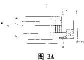
图3A为本发明液晶显示面板与框架结构籍由双面胶连结固定的侧视剖面图;3A is a side view sectional view of the liquid crystal display panel and the frame structure of the present invention connected and fixed by double-sided adhesive;
图3B为本发明液晶显示面板与框架结构籍由胶带连结固定的侧视剖面图;3B is a side view sectional view of the liquid crystal display panel and the frame structure of the present invention connected and fixed by adhesive tape;
图3C为本发明液晶显示面板与框架结构藉由卡榫连结固定的侧视剖面图;3C is a side sectional view of the liquid crystal display panel and the frame structure of the present invention connected and fixed by tenons;
图3D为本发明液晶显示面板与框架结构藉由扣点连结固定的侧视剖面图;3D is a side sectional view of the liquid crystal display panel and the frame structure of the present invention connected and fixed by buckle points;
图4为本发明卡榫的立体示意图;以及Fig. 4 is a three-dimensional schematic view of the tenon of the present invention; and
图5为本发明扣点的立体示意图。Fig. 5 is a three-dimensional schematic view of the buckle point of the present invention.
附图标号说明:Explanation of reference numbers:
2、平面显示器 3、30、液晶显示面板 4、44、双面胶2. Flat panel display 3. 30. Liquid crystal display panel 4. 44. Double-sided tape
6、40、框架结构 8、触控笔 9、38、上玻璃基板6. 40.
10、36、下玻璃基板 12、间隙物 13、液晶层 14、液晶分子10. 36.
32、可视区 34、黑色矩阵 42、胶框 46、胶带32.
48、卡榫 50、扣点 52、驱动晶片 33、非可视区48.
具体实施方式Detailed ways
关于本发明的技术解决方案及其优点,可藉由以下的发明详述及所附图式得到进一步的了解。Regarding the technical solutions and advantages of the present invention, a further understanding can be obtained from the following detailed description of the invention and the accompanying drawings.
请参阅图2,图2为本发明连接物分布区域的俯视图。本发明是关于平面显示器所使用的液晶显示面板30,特别是关于触控式液晶显示面板30。以图2俯视图来看液晶显示面板30,液晶显示面板30中,包含一块区域为可视区32,以及一块非可视区33。可视区32用以提供平面显示器显示画面之用,其余部分则为非可视区33。另外,液晶显示面板30中黑色矩阵34所分布的区域,即用以提供所欲显示的画面而为可视区,但是一般来说,黑色矩阵34所分布的区域会较可视区32稍微大一些,与上玻璃基板38大小一致,不仅为了方便制作,还可以确保可视区32显示完整的画面。下玻璃基板36最大,是为了额外放置驱动晶片52,以致整个液晶显示面板30的最外边缘即是下玻璃基板36的边缘。Please refer to FIG. 2 . FIG. 2 is a top view of the distribution area of the connectors of the present invention. The present invention relates to a liquid
请参阅图3A、图3B、图3C及图3D。图3A、图3B、图3C及图3D分别为本发明液晶显示面板30与框架结构40藉由连接物44、46、48、50连结固定的侧视剖面图。本发明藉由一框架结构40以保护并固定液晶显示面板30。液晶显示面板30包含一下玻璃基板36及一连接物44、46、48、50、一上玻璃基板38、一黑色矩阵34及一胶框42。Please refer to FIG. 3A , FIG. 3B , FIG. 3C and FIG. 3D . 3A , 3B , 3C and 3D are side cross-sectional views of the liquid
利用上玻璃基板38以及下玻璃基板36包夹,以成为液晶显示面板30的主体。黑色矩阵34置于上玻璃基板38的内侧,大小与上玻璃基板38相同,范围较可视区32略大。胶框42置于液晶显示面板30周围与框架结构40之间,以稳定液晶显示面板30避免水平方向移动。下玻璃基板36水平贴放于框架结构40的一内侧,并藉由连接物44、46、48、50以固定连接下玻璃基板36以及框架结构40。连接物可以采用双面胶44、一胶带4The
6、一扣点50、或是一卡榫48。其中连接物44、46、48、50所分布的区域,必须与液晶显示面板30的可视区32垂直方向不相重叠,也就是连接物44、46、48、50必须分布于非可视区33所垂直对应的位置。或者是,连接物44、46、48、50所分布的区域,与液晶显示面板30的黑色矩阵34所分布的垂直区域不相重叠,因为通常为了制造方便,黑色矩阵34所分布的区域会较可视区32大,所以以黑色矩阵34所分布的区域来定义可视区32,以限制连接物44、46、48、50所分布的区域,使下玻璃基板36与框架结构40紧密贴合,也可以达到防止波纹的功效。6. One
请参阅图3A,如前述的液晶显示面板30,其中该连接物可以为一双面胶44、一胶带46、一扣点50、或是一卡榫48。若采用双面胶44,则需将双面胶44设置于下玻璃基板36与框架结构40之间,利用双面的黏性以固定黏接下玻璃基板36以及框架结构40。在此进一步强调,双面胶44所分布的区域与液晶显示面板30的可视区32垂直方向或是黑色矩阵34分布的垂直区域不相重叠,而贴于可视区32范围外与下玻璃基板36的边缘之间,或是贴于黑色矩阵34所分布的区域外与下玻璃基板36的边缘之间,也就是必须贴于非可视区33所垂直对应的区域范围中。Please refer to FIG. 3A , such as the aforementioned liquid
请参阅图3B,胶带46包覆黏贴下玻璃基板36与框架结构40,利用胶带46一侧有黏性的部分,自下玻璃基板36上表面,沿着下玻璃基板36侧表面,黏着包覆至框架结构40的内侧表面,藉此以固定黏接下玻璃基板36以及框架结构40。同样也需强调的是,胶带46所分布的区域与该液晶显示面板30的可视区32垂直方向或是黑色矩阵34分布的垂直区域不相重叠,而贴于可视区32外与下玻璃基板36的边缘之间,或是贴于黑色矩阵34所分布的区域外与下玻璃基板36的边缘之间,也就是必须贴于非可视区33所垂直对应的区域范围中。Please refer to FIG. 3B , the
请参阅图3C并配合图4,图4为本发明卡榫48的立体示意图。卡榫48为一长形的卡合槽,以卡合下玻璃基板36,藉此扣夹下玻璃基板36并连接框架结构40,以固定连接该下玻璃基板36以及该框架结构40。卡榫48可以是延伸自胶框42的相同材质,而与胶框42一体成型。需强调的是,卡榫48所分布的区域与液晶显示面板30的可视区32垂直方向或是黑色矩阵34分布的垂直区域不相重叠,而分布于可视区32外与下玻璃基板36的边缘之间,或是分布于黑色矩阵34所分布的区域外与下玻璃基板36的边缘之间,也就是必须分布于非可视区33所垂直对应的区域范围中。Please refer to FIG. 3C together with FIG. 4 . FIG. 4 is a three-dimensional schematic diagram of the
请参阅图3D并配合图5,图5为本发明扣点50的立体示意图。扣点50用以扣夹下玻璃基板36与框架结构40,以固定连接下玻璃基板36以及框架结构40,扣点50可以是延伸自胶框42的相同材质,而与胶框42一体成型。扣点50与卡榫48不同的是,扣点50为一一分离的卡合物,以卡合下玻璃基板36与框架结构40,卡榫48为一长形的卡合槽,以卡合下玻璃基板36与框架结构40,藉此扣点50以固定连接该下玻璃基板36以及该框架结构40。需强调的是,扣点50所分布的区域与液晶显示面板30的可视区32垂直方向或是黑色矩阵34分布的垂直区域不相重叠,而分布于可视区32外与下玻璃基板36的边缘之间,或是分布于黑色矩阵34所分布的区域外与下玻璃基板36的边缘之间,也就是必须分布于非可视区33所垂直对应的区域范围中。Please refer to FIG. 3D together with FIG. 5 . FIG. 5 is a three-dimensional schematic diagram of the
因此,藉由本发明液晶显示面板30的连接物44、46、48、50,以及连接物固定连接该框架结构40以及该下玻璃基板36的位置,与该液晶显示面板30的可视区32垂直方向或是黑色矩阵34分布的垂直区域不相重叠,也就是连接物44、46、48、50必须分布于非可视区33。藉此,使下玻璃基板36与框架结构40紧密贴合,可以以经济的方式,防止该液晶显示面板30的显示画面受触控操作时,由于受力不均造成液晶层变形,使平面显示器所显示的画面产生波纹。Therefore, by the
虽然本发明已以优选实施例揭示,但其并非用以限定本发明,任何本领域的技术人员,在不脱离本发明的构思和范围的前提下所作出的等同组件的置换,或依本发明专利保护范围所作的等同变化与修饰,皆应仍属本专利涵盖之范畴。Although the present invention has been disclosed with preferred embodiments, it is not intended to limit the present invention. Any person skilled in the art can make replacements of equivalent components without departing from the concept and scope of the present invention, or replace them according to the present invention. The equivalent changes and modifications made in the scope of patent protection shall still fall within the scope of this patent.
Claims (10)
Priority Applications (1)
| Application Number | Priority Date | Filing Date | Title |
|---|---|---|---|
| CNB031410529ACN1310068C (en) | 2003-06-09 | 2003-06-09 | LCD panel fixed to the frame structure to prevent ripples |
Applications Claiming Priority (1)
| Application Number | Priority Date | Filing Date | Title |
|---|---|---|---|
| CNB031410529ACN1310068C (en) | 2003-06-09 | 2003-06-09 | LCD panel fixed to the frame structure to prevent ripples |
Publications (2)
| Publication Number | Publication Date |
|---|---|
| CN1567037A CN1567037A (en) | 2005-01-19 |
| CN1310068Ctrue CN1310068C (en) | 2007-04-11 |
Family
ID=34470826
Family Applications (1)
| Application Number | Title | Priority Date | Filing Date |
|---|---|---|---|
| CNB031410529AExpired - LifetimeCN1310068C (en) | 2003-06-09 | 2003-06-09 | LCD panel fixed to the frame structure to prevent ripples |
Country Status (1)
| Country | Link |
|---|---|
| CN (1) | CN1310068C (en) |
Families Citing this family (2)
| Publication number | Priority date | Publication date | Assignee | Title |
|---|---|---|---|---|
| CN101995675B (en)* | 2009-08-14 | 2012-10-31 | 英业达股份有限公司 | Liquid crystal display device |
| CN104915064B (en)* | 2015-07-02 | 2018-05-08 | 合肥鑫晟光电科技有限公司 | A kind of touch control liquid crystal display device |
Citations (5)
| Publication number | Priority date | Publication date | Assignee | Title |
|---|---|---|---|---|
| US5838401A (en)* | 1996-03-15 | 1998-11-17 | Canon Kabushiki Kaisha | Impact resistant crystal apparatus |
| JPH11202787A (en)* | 1998-01-13 | 1999-07-30 | Hitachi Ltd | Liquid crystal display |
| JP2001356321A (en)* | 2000-06-09 | 2001-12-26 | Fujitsu Ltd | Liquid crystal display device |
| US6392724B2 (en)* | 2000-02-24 | 2002-05-21 | Lg. Philips Lcd Co., Ltd. | LCD module having improved fixing structure |
| JP2002311418A (en)* | 2001-04-17 | 2002-10-23 | Nec Corp | Liquid crystal display |
- 2003
- 2003-06-09CNCNB031410529Apatent/CN1310068C/ennot_activeExpired - Lifetime
Patent Citations (5)
| Publication number | Priority date | Publication date | Assignee | Title |
|---|---|---|---|---|
| US5838401A (en)* | 1996-03-15 | 1998-11-17 | Canon Kabushiki Kaisha | Impact resistant crystal apparatus |
| JPH11202787A (en)* | 1998-01-13 | 1999-07-30 | Hitachi Ltd | Liquid crystal display |
| US6392724B2 (en)* | 2000-02-24 | 2002-05-21 | Lg. Philips Lcd Co., Ltd. | LCD module having improved fixing structure |
| JP2001356321A (en)* | 2000-06-09 | 2001-12-26 | Fujitsu Ltd | Liquid crystal display device |
| JP2002311418A (en)* | 2001-04-17 | 2002-10-23 | Nec Corp | Liquid crystal display |
Also Published As
| Publication number | Publication date |
|---|---|
| CN1567037A (en) | 2005-01-19 |
Similar Documents
| Publication | Publication Date | Title |
|---|---|---|
| CN104915064B (en) | A kind of touch control liquid crystal display device | |
| CN202887620U (en) | Flexible display panel and display device including the same | |
| CN103970336B (en) | Touch display panel and touch display device | |
| CN1213449C (en) | Touching Panel | |
| JP4490461B2 (en) | Liquid crystal display | |
| WO2019085493A1 (en) | Display device | |
| CN1940660A (en) | Display device | |
| CN205485162U (en) | Display device | |
| CN204679739U (en) | Display screen, display screen component and terminal | |
| CN104063084B (en) | Touch control display device | |
| US20140022465A1 (en) | Color filter substrate, touch display panel and touch display device | |
| KR102040652B1 (en) | Front Cover Glass Having Curved Corner For Mobile Communication Device | |
| US20190369431A1 (en) | Display panel and display device | |
| CN1293410C (en) | Manufacturing method for liquid-crystal displaying device integrating touch board | |
| JP2007178758A (en) | Display device | |
| US20180373091A1 (en) | Display panel | |
| CN117631381A (en) | Display panel | |
| CN115497383A (en) | Flexible display module and display device | |
| CN1831595A (en) | Display device with enlarged display area | |
| CN112213893B (en) | Display device | |
| CN108761871A (en) | A kind of Liquid Crystal Module improving display area area | |
| CN201066422Y (en) | Electronic paper display | |
| US11822204B2 (en) | Electronic paper package structure | |
| CN1310068C (en) | LCD panel fixed to the frame structure to prevent ripples | |
| JP2008210199A (en) | Touch panel, manufacturing method for it, and electronic apparatus |
Legal Events
| Date | Code | Title | Description |
|---|---|---|---|
| C06 | Publication | ||
| PB01 | Publication | ||
| C10 | Entry into substantive examination | ||
| SE01 | Entry into force of request for substantive examination | ||
| C14 | Grant of patent or utility model | ||
| GR01 | Patent grant | ||
| CX01 | Expiry of patent term | ||
| CX01 | Expiry of patent term | Granted publication date:20070411 |