CN1308148C - Cleaning method of inkjet printer and recovery system - Google Patents
Cleaning method of inkjet printer and recovery systemDownload PDFInfo
- Publication number
- CN1308148C CN1308148CCNB018107435ACN01810743ACN1308148CCN 1308148 CCN1308148 CCN 1308148CCN B018107435 ACNB018107435 ACN B018107435ACN 01810743 ACN01810743 ACN 01810743ACN 1308148 CCN1308148 CCN 1308148C
- Authority
- CN
- China
- Prior art keywords
- ink
- printing
- calotte
- mentioned
- printhead
- Prior art date
- Legal status (The legal status is an assumption and is not a legal conclusion. Google has not performed a legal analysis and makes no representation as to the accuracy of the status listed.)
- Expired - Fee Related
Links
Images


Classifications
- B—PERFORMING OPERATIONS; TRANSPORTING
- B41—PRINTING; LINING MACHINES; TYPEWRITERS; STAMPS
- B41J—TYPEWRITERS; SELECTIVE PRINTING MECHANISMS, i.e. MECHANISMS PRINTING OTHERWISE THAN FROM A FORME; CORRECTION OF TYPOGRAPHICAL ERRORS
- B41J2/00—Typewriters or selective printing mechanisms characterised by the printing or marking process for which they are designed
- B41J2/005—Typewriters or selective printing mechanisms characterised by the printing or marking process for which they are designed characterised by bringing liquid or particles selectively into contact with a printing material
- B41J2/01—Ink jet
- B41J2/135—Nozzles
- B41J2/165—Prevention or detection of nozzle clogging, e.g. cleaning, capping or moistening for nozzles
- B41J2/16505—Caps, spittoons or covers for cleaning or preventing drying out
- B41J2/16508—Caps, spittoons or covers for cleaning or preventing drying out connected with the printer frame
- B—PERFORMING OPERATIONS; TRANSPORTING
- B41—PRINTING; LINING MACHINES; TYPEWRITERS; STAMPS
- B41J—TYPEWRITERS; SELECTIVE PRINTING MECHANISMS, i.e. MECHANISMS PRINTING OTHERWISE THAN FROM A FORME; CORRECTION OF TYPOGRAPHICAL ERRORS
- B41J2/00—Typewriters or selective printing mechanisms characterised by the printing or marking process for which they are designed
- B41J2/005—Typewriters or selective printing mechanisms characterised by the printing or marking process for which they are designed characterised by bringing liquid or particles selectively into contact with a printing material
- B41J2/01—Ink jet
- B41J2/135—Nozzles
- B41J2/165—Prevention or detection of nozzle clogging, e.g. cleaning, capping or moistening for nozzles
- B41J2/16517—Cleaning of print head nozzles
- B41J2/1652—Cleaning of print head nozzles by driving a fluid through the nozzles to the outside thereof, e.g. by applying pressure to the inside or vacuum at the outside of the print head
- B41J2/16523—Waste ink transport from caps or spittoons, e.g. by suction
- B—PERFORMING OPERATIONS; TRANSPORTING
- B41—PRINTING; LINING MACHINES; TYPEWRITERS; STAMPS
- B41J—TYPEWRITERS; SELECTIVE PRINTING MECHANISMS, i.e. MECHANISMS PRINTING OTHERWISE THAN FROM A FORME; CORRECTION OF TYPOGRAPHICAL ERRORS
- B41J2/00—Typewriters or selective printing mechanisms characterised by the printing or marking process for which they are designed
- B41J2/005—Typewriters or selective printing mechanisms characterised by the printing or marking process for which they are designed characterised by bringing liquid or particles selectively into contact with a printing material
- B41J2/01—Ink jet
- B41J2/135—Nozzles
- B41J2/165—Prevention or detection of nozzle clogging, e.g. cleaning, capping or moistening for nozzles
- B41J2/16517—Cleaning of print head nozzles
- B41J2/1652—Cleaning of print head nozzles by driving a fluid through the nozzles to the outside thereof, e.g. by applying pressure to the inside or vacuum at the outside of the print head
- B41J2/16526—Cleaning of print head nozzles by driving a fluid through the nozzles to the outside thereof, e.g. by applying pressure to the inside or vacuum at the outside of the print head by applying pressure only
Landscapes
- Engineering & Computer Science (AREA)
- Environmental & Geological Engineering (AREA)
- Ink Jet (AREA)
- Accessory Devices And Overall Control Thereof (AREA)
Abstract
Description
Translated fromChinese技术领域technical field
本发明涉及一种喷墨打印机,它借助设置在打印头上的喷嘴喷射墨而在打印介质上形成图像。The present invention relates to an ink jet printer which forms an image on a printing medium by ejecting ink from nozzles provided on a printing head.
背景技术Background technique
一种使用喷墨方法的打印机,它可以喷射墨到打印介质上,比如打印纸上,以便在其上形成图像,已知它作为一种信号处理设备的输出装置使用,比如计算机或工作站的。这种喷墨打印机通常具有打印头,在它们每个上面设置喷射墨的喷嘴,托架,在其上安装打印头,它在预定的方向上前后移动,以及打印介质传送器,它沿一个方向(打印介质传送方向)与预定的方向成直角传送打印介质。A printer using an inkjet method which ejects ink onto a printing medium such as printing paper to form an image thereon, known for use as an output device of a signal processing apparatus such as a computer or a workstation. Such inkjet printers generally have print heads each of which is provided with nozzles for ejecting ink, a carriage on which the print head is mounted, which moves back and forth in a predetermined direction, and a print medium conveyer, which moves in one direction (Print Medium Transport Direction) The print medium is transported at right angles to a predetermined direction.
当在打印纸上形成一个图像时,被打印介质传送器传送的打印纸暂时地停止,而在预定的方向上前后移动托架,墨根据包括图像信息的图像信号,由喷嘴喷出,从而在图像形成区域内形成图像带,它与喷嘴出口(墨喷射出口)在打印纸上相对。在此之后,打印纸供给一个图像带,以及随后停止,而在预定的方向上再次前后移动托架,墨根据图像信号由喷嘴喷出,从而在打印纸的图像形成区域内形成另一个图像带。借助这种工序的重复,在打印纸上形成完整的图像。When an image is formed on the printing paper, the printing paper conveyed by the printing medium conveyer is temporarily stopped, and the carriage is moved back and forth in a predetermined direction, and the ink is ejected from the nozzles according to the image signal including the image information, thereby An image band is formed in the image forming area, which is opposed to nozzle outlets (ink ejection outlets) on the printing paper. After that, the printing paper feeds one image band, and then stops, and the carriage is moved back and forth again in a predetermined direction, ink is ejected from the nozzles according to the image signal, thereby forming another image band in the image forming area of the printing paper . By repeating this process, a complete image is formed on the printing paper.
因为墨(打印液)是由在这种喷墨打印机打印用的打印头直接地喷出,打印头必须保持在这样的状态,使墨能在任何的时间喷射。这样就要求一系列的在其它类型打印机上不需要的特殊的程序。Since ink (printing liquid) is directly ejected from the print head used for printing in this ink jet printer, the print head must be kept in such a state that ink can be ejected at any time. This requires a series of special procedures not required on other types of printers.
[吸收][absorb]
当气体或者气泡混合进入供给通道,墨通过此通道供给至作为墨出口的喷嘴,或者进入墨贮箱(公共的液体室),它接近喷嘴,以及当这些气泡变大,以致它们防碍墨供给至喷嘴,墨就不能正确地喷射。为了解决此问题,存在于公共的液体室的前部区和其内的气泡被施加至喷嘴表面的负压吸取和消除。这个程序称为吸收。如同下述,吸收程序进行时,也可将帽罩由打印头取下,借助预先的喷射清除积聚在帽罩内的墨。(本发明所述的吸收是后吸收)。When gas or air bubbles mix into the supply channel, ink is supplied through this channel to the nozzle as the ink outlet, or into the ink tank (common liquid chamber), which is close to the nozzle, and when these air bubbles become so large that they obstruct the ink supply to the nozzles, the ink will not be ejected correctly. In order to solve this problem, air bubbles existing in the front region of the common liquid chamber and therein are sucked and eliminated by the negative pressure applied to the nozzle surface. This procedure is called absorption. As described below, the cap can also be removed from the printhead while the absorbing process is in progress, and ink accumulated in the cap can be removed by means of a pre-spray. (The absorption described in the present invention is post-absorption).
[擦拭][wipe]
物理杂质(纸粉,墨等),它们粘接在喷嘴排列表面(侧面)以及妨碍墨的喷射,某些时候妨碍墨的正确喷射。为了清除这些物理杂质,使用柔性的片状元件,比如橡胶片状元件擦拭侧面。这个程序称为擦拭程序,擦拭用的工具称为擦拭片。Physical impurities (paper dust, ink, etc.), which adhere to the nozzle arrangement surface (sides) and hinder ink ejection, sometimes prevent ink from being ejected correctly. To remove these physical impurities, a flexible sheet member, such as a rubber sheet member, is used to wipe the sides. This procedure is called a wiping procedure, and the tool used for wiping is called a wiping sheet.
[预先的喷射][lower jet]
在图像形成时不是全部的喷嘴用于喷射墨。因此,没有喷射墨的喷嘴是干燥的以及这些喷嘴有时会妨碍墨的喷射。在预定的时间间隔在不是打印纸的部件上喷射墨以防止墨干燥以保证良好的图像质量,此程序就是预先的喷射。此程序也称为“预先喷射”。Not all nozzles are used to eject ink at the time of image formation. Therefore, the nozzles that do not eject ink are dry and these nozzles sometimes prevent the ejection of ink. Pre-jet is a procedure that sprays ink on parts other than paper at predetermined intervals to prevent ink from drying and to ensure good image quality. This procedure is also known as "pre-spray".
[盖帽罩][cap cover]
在不打印时间用一个帽罩盖住侧面,以防喷嘴内的墨干燥的程序,称为盖帽罩程序。在帽罩内放入被吸收的墨浸渍至一定程度的吸收性物质,以防止干燥。The process of covering the side with a cap during non-printing time to prevent the ink in the nozzle from drying is called a capping process. An absorbent material impregnated with absorbed ink to a certain extent is placed in the cap to prevent drying.
应该注意,在打印时的预先喷射一般是在时间控制下一点一点地进行,因此,少量的墨在帽罩内积聚较长的时间。此外,即使进行程序以吸收积聚的墨,这时在帽罩内的吸收性物质内已没有足够的墨区,空气被吸取,以及因而残余的墨保持在帽罩内,为了这个原因,在帽罩或在吸收泵内的墨的粘度增加(粘度增加),作为其结果,墨粘接至帽罩和吸收泵,以及至墨通道,通过它墨流动至废墨槽。It should be noted that the pre-ejection at the time of printing is generally carried out bit by bit under time control, therefore, a small amount of ink accumulates in the cap for a long time. In addition, even if the procedure is performed to absorb the accumulated ink, there is not enough ink area in the absorbent material in the cap at this time, the air is sucked, and thus the residual ink remains in the cap. For this reason, the cap The viscosity of the ink in the cap or in the suction pump increases (viscosity increase), and as a result, the ink sticks to the cap and the suction pump, and to the ink channel through which the ink flows to the waste ink tank.
粘接至吸收泵或流动通道的一些墨被吸收程序重新溶解,以及被传送至废墨槽。然而,这里仍可能有一种可能性,墨最终堵塞流动通道,从而引起泵失效或者引起喷射在帽罩内的墨流溢。当使用一种高耐水性的加颜料的墨时,由于它难以重新溶解而使这个问题最为明显。Some of the ink that sticks to the suction pump or flow channel is redissolved by the suction process and sent to the waste ink tank. However, there may still be a possibility here that the ink ends up clogging the flow channel, causing the pump to fail or cause the ink ejected inside the cap to overflow. This problem is most pronounced when using a high water fastness pigmented ink due to its difficulty in redissolving.
从上述的观点考虑,本发明的目的是提供一种喷墨打印机以及其恢复系统清洗方法,它可以防止在恢复系统中产生墨粘接,以及它可以平稳地进行吸收和预先喷射程序。From the above viewpoint, it is an object of the present invention to provide an ink jet printer and its recovery system cleaning method which can prevent ink sticking in the recovery system and which can smoothly perform the absorption and pre-ejection procedures.
发明内容Contents of the invention
本发明提供了一种喷墨打印机恢复系统的清洗方法,此打印机由打印头的喷嘴喷射墨滴,以便在打印纸上记录,所述方法包括以下步骤:计算一个累积次数计数,即将墨由上述的打印头上的喷嘴预先喷射入贮存有废墨的帽罩内的计数;当以预定的时间进行吸收程序以吸收已经喷射入帽罩内的墨时,另外喷射墨进入帽罩,其次数计数等于一个预定的计数值和上述累积次数计数值之间的差数;以及进行吸收程序,以吸收贮存在帽罩内的墨。The present invention provides a cleaning method for a recovery system of an inkjet printer. The printer ejects ink droplets from the nozzles of the print head so as to record on printing paper. The number of times that the nozzles on the print head are pre-injected into the cap that stores waste ink; when the absorption process is performed at a predetermined time to absorb the ink that has been ejected into the cap, the number of times that the ink is additionally injected into the cap is counted is equal to a difference between a predetermined count value and the above-mentioned accumulation count value; and performing an absorbing process to absorb ink stored in the cap.
本发明还提供了一种喷墨打印机,具有:一个打印头,用于由喷嘴喷射墨滴,以便在打印纸上记录;一个帽罩,用于防止喷嘴干燥;预先喷射器件,用于在非打印时间将上述的喷墨打印头放置到对着帽罩的位置,以便由喷嘴喷射墨滴,以防止不良的打印;墨吸收器件,连接至上述的帽罩,用于吸收贮存在上述的帽罩内的墨;计算器件,用于计算墨由上述的喷嘴喷射至上述的帽罩的次数计数;以及控制器件,当以预定的时间进行一个吸收程序,以吸收已喷射进入帽罩的墨时,用于使墨顺序地喷射进入帽罩;其次数计数等于一个预定的计数值和一个累积的次数计数之间的差数,以及随后进行所述的吸收程序,以吸收已贮存在帽罩内的墨。The present invention also provides an inkjet printer having: a print head for ejecting ink droplets from nozzles for recording on printing paper; a cap for preventing nozzles from drying; a pre-ejection device for At the time of printing, the above-mentioned inkjet printing head is placed in a position facing the cap so that ink droplets are ejected from the nozzles to prevent bad printing; the ink absorbing device is connected to the above-mentioned cap for absorbing the ink stored in the above-mentioned cap. ink in the cap; counting means for counting the number of times ink is ejected from the above-mentioned nozzle to the above-mentioned cap; and control means for absorbing the ink that has been ejected into the cap when performing an absorbing process at a predetermined time , for sequentially ejecting ink into the cap; its number of counts is equal to the difference between a predetermined count value and an accumulated count, and then the absorbing process is performed to absorb the ink that has been stored in the cap of ink.
按照本发明的方法和打印机,如同上述,至少在打印之前或打印结束时保留一些量的墨在墨流动通道内流动,而不需要对普通的恢复设备作大的改形,以防止墨粘接到恢复系统的各部件上。According to the method and printer of the present invention, as described above, at least some amount of ink is retained to flow in the ink flow channel before printing or at the end of printing, without requiring major modifications to conventional recovery equipment to prevent ink from sticking to various components of the recovery system.
在另一方面,按照本发明的恢复系统清洗用的方法是一种喷墨打印机的恢复系统清洗用的方法,它由打印头的喷嘴喷射墨滴,以便在打印纸上记录,在其中,由帽罩吸收废墨的吸收程序在打印之后进行,直至由设置在帽罩的下游的墨流动通道排放墨,以及在其中,吸收程序是直接在打印之前或打印中进行,至这样的程度,墨已由帽罩排出,但仍保持在墨流动通道内。On the other hand, a method for cleaning a recovery system according to the present invention is a method for cleaning a recovery system of an inkjet printer, which ejects ink droplets from nozzles of a print head to record on printing paper, wherein, by The absorbing process in which the cap absorbs waste ink is performed after printing until the ink is discharged from the ink flow passage provided downstream of the cap, and in which the absorbing process is performed directly before printing or during printing, to such an extent that the ink Expelled by the cap but remains in the ink flow path.
这样允许在打印之前已放出的墨保持在流动通道内,在打印时溶解粘接在墨通道内的墨,以及使溶解的墨在打印结束时流动,从而解决了长时间贮存产生的粘接的墨的问题。作为其结果,吸收程序和预先喷射程序可以平稳地进行很长时间以及保证了良好的图像质量。This allows the ink that has been released before printing to remain in the flow channel, dissolves the ink stuck in the ink channel during printing, and allows the dissolved ink to flow at the end of printing, thereby solving the problem of adhesion caused by long-term storage. Ink problem. As a result, the absorption process and the pre-ejection process can be performed smoothly for a long time and good image quality is ensured.
在另一方面,按照本发明的恢复系统用的清洗方法是一种喷墨打印机的恢复系统清洗用的方法,它由打印头的喷嘴喷射墨滴,以便在打印纸上记录,在其中当以预定的时间进行预先喷射程序时,第一预先喷射程序,它是防止喷嘴干燥的程序,以及第二预先喷射程序,它是以比第一预先喷射程序计数值更长时间的程序,它们转换或者以预定的时间间隔交替地进行。On the other hand, a cleaning method for a recovery system according to the present invention is a method for cleaning a recovery system of an inkjet printer, which ejects ink droplets from nozzles of a print head to record on printing paper, wherein when using When the pre-injection program is performed at a predetermined time, the first pre-injection program, which is a program to prevent nozzle drying, and the second pre-injection program, which is a program with a longer count value than the first pre-injection program, they switch or Alternately at predetermined time intervals.
按照本发明的另一喷墨打印机,它具有一个打印头,用于由喷嘴喷射墨滴至打印纸上;以便记录,一个帽罩,用于防止喷嘴干燥;预先喷射器件,用于在非打印时间将喷墨打印头放置到对着帽罩的位置,以便由喷嘴喷射墨滴,以防止不良的打印;墨吸收器件,它连接至帽罩,用于吸收贮存在帽罩内的墨;判断器件,用于根据预定的准则判断预定的判断数据,此判断数据是事先收集的,用于判断;以及控制器件,用于转换第一打印程序和第二打印程序,以便根据判断器件的判断结果执行,第一打印程序包括第一预先喷射程序,它至少在开始打印之前或打印之后预先地喷射预定量的墨,第二打印程序包括第二预先喷射程序,它预先地喷射比至少在开始打印之前或打印之后预定量更多的墨。According to another ink-jet printer of the present invention, it has a printing head, is used for ejecting ink drop on the printing paper by nozzle; For recording, a cap is used for preventing nozzle from drying; Time to place the inkjet print head against the cap so that ink droplets are ejected from the nozzles to prevent bad printing; the ink absorbing device, which is connected to the cap, is used to absorb the ink stored in the cap; judge A device for judging predetermined judging data according to a predetermined criterion, the judging data is collected in advance and used for judging; Execution, the first printing program includes a first pre-ejection program, which ejects a predetermined amount of ink in advance at least before starting to print or after printing, and the second printing program includes a second pre-ejection program, which pre-ejects more ink than at least at the beginning of printing. Order more ink before or after printing.
如上所述,第一打印程序和第二打印程序的转换,它根据预定的准则决定预先的喷射墨量的区别,允许至少在打印之前和打印结束时规则地供给一定量的墨至墨通道。这样防止了墨粘接到恢复系统的部件上。As described above, switching of the first printing program and the second printing program, which determines the difference in the amount of ejected ink in advance according to predetermined criteria, allows regular supply of a certain amount of ink to the ink channel at least before printing and at the end of printing. This prevents ink from adhering to components of the recovery system.
当打印时累积的打印点数达到预定的点数,当打印时的打印页数达到预定的格式数,或者当打印时间达到预定的时间,以预定的时间间隔进行转换。When the accumulated print dots reach a predetermined number of dots when printing, when the number of printed pages when printing reaches a predetermined number of formats, or when the printing time reaches a predetermined time, switching is performed at predetermined time intervals.
附图说明Description of drawings
图1是按照本发明的一个实施例的喷墨打印机的外形的透视图;1 is a perspective view of an outline of an inkjet printer according to an embodiment of the present invention;
图2是图1所示恢复系统的帽罩和一种颜色墨的相应的泵的示意图;Figure 2 is a schematic diagram of the cap of the recovery system shown in Figure 1 and the corresponding pump for one color of ink;
图3是一个方框图,示出图1所示的喷墨打印机的控制硬件的一般形状;Fig. 3 is a block diagram showing the general shape of the control hardware of the inkjet printer shown in Fig. 1;
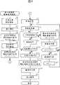
图4是一个流程图,示出本发明的第一实施例的喷墨打印机的打印程序;Fig. 4 is a flowchart showing the printing procedure of the inkjet printer of the first embodiment of the present invention;
图5是一个流程图,示出本发明的第二实施例的喷墨打印机的打印程序;Fig. 5 is a flowchart showing the printing procedure of the inkjet printer of the second embodiment of the present invention;
图6是一个流程图,示出本发明的第三实施例的喷墨打印机的恢复系统的清洗程序;Fig. 6 is a flowchart showing the cleaning procedure of the recovery system of the inkjet printer of the third embodiment of the present invention;
图7是一个表格,示出按照本发明的第三实施例的点计数第一打印程序和第二打印程序转换用的准则;FIG. 7 is a table showing a dot counting criterion for switching between a first printing program and a second printing program according to a third embodiment of the present invention;
图8是一个表格,示出按照本发明的第三实施例的打印的页数第一打印程序和第二打印程序转换用的准则;Fig. 8 is a table showing the number of printed pages according to the third embodiment of the present invention and a criterion for switching between the first printing program and the second printing program;
图9是一个表格,示出按照本发明的第三实施例的打印的时间(h)第一打印程序和第二打印程序转换用的准则;以及Fig. 9 is a table showing time (h) criteria for switching between the first printing program and the second printing program according to the third embodiment of the present invention; and
图10是一个流程图,示出本发明的第三实施例中第一打印程序和第二打印程序是如何转换的。Fig. 10 is a flowchart showing how the first printing program and the second printing program are converted in the third embodiment of the present invention.
具体实施方式Detailed ways
以下本发明的一些实施例将结合附图予以说明。Some embodiments of the present invention will be described below with reference to the accompanying drawings.
参见图1,示出的打印机是按照本发明的喷墨打印机的一个实例,予以说明。图1是一个透视图,示出打印机的总的外形。Referring to Fig. 1, a printer shown as an example of an ink jet printer according to the present invention will be described. Fig. 1 is a perspective view showing the general appearance of the printer.
打印机10具有一个台板14,在其上打印纸12沿箭头A的传送方向放置。在台板14的上面设置两条扫描轨道(引导轨道)16,它们与台板14平行前进。在扫描轨道16上一个托架20被电动机(图中未示出)和皮带18沿箭头B和C方向前后移动(与箭头A方向垂直),它借助滑动轴承安装(图中未示出)。The
托架20具有4个打印头22K(黑色),22C(蓝色),22M(深红色)和22Y(黄色),每个具有喷嘴出口(图中未示出),用以喷出墨。在此墨出口的前面是一个图像形成区,它的带宽大致等于喷嘴柱的长度,假定在打印纸12上。墨由墨出口喷出至图像形成区,以便在此部分内形成一条图像带。The
在托架20能移动入的区域的一端以及在离开图像形成区的位置设置一个恢复装置30。此装置由喷嘴强制地吸收墨,以清洗打印头22上的墨供给通道和喷嘴,以及恢复打印头22的墨喷射状况至原始的喷射状况。恢复装置30具有4个橡胶帽罩32K,32C,32M和32Y,每个可拆卸地盖住4个打印头22K,22C,22M和22Y,的相应的喷嘴出口。一根管子(图中未示出)的一端连接至每个帽罩32K,32C,32M和32Y,以及管子的另一端连接至吸收泵(图中未示出)。4个帽罩32K,32C,32M和32Y,固定在帽罩支座32。A restoring
当在打印纸12,比如卷筒纸上形成图像时,打印纸12放置在台板14上,并且打印纸12保持在传送滚筒24和压紧滚筒26之间,传送滚筒24具有一部分周边由设置在台板14上的开口暴露,以及压紧滚筒26保持着打印纸12的两端,传送滚筒24被一个电动机(图中未示出)转动,以便传送打印纸12。When forming an image on a
另一方面,托架20根据图像信号,包括来自打印头控制器130的图像信息(参见图3),按照箭头B和C的方向前后移动至打印头22K,22C,22M和22Y,墨由喷嘴喷出以形成在打印纸12上的图像形成区的一条带。当需要在图像成形程序中由喷嘴吸收墨以清洗喷嘴时,托架20移动至恢复装置30的上面位置,以进行预定的恢复程序。当图像成形结束,设置在托架20上的一个切割器(图中未示出)伸出至预定的位置以切割打印纸12为预定的长度。On the other hand, the
图2的示意图示出图1所示的恢复装置30的帽罩32K和一种颜色(比如黑色)用的相应的泵34。墨通道33a的一端连接至帽罩32K的底部以及泵34的另一端,此外,另一墨流动通道33b的一端连接至泵34的底部,墨通道33b的另一端连接至一个废墨槽(图中未示出)。FIG. 2 is a schematic
图3的方框图示出上述的喷墨打印机的控制硬件的一般的形状。由主计算机传送的图像数据一次性地保持在打印机的接收缓冲器121内。相反地,指示数据传送是否正确的数据,以及指示打印机工作状况的数据是由打印机传送至主计算机。保持在接收缓冲器121内的数据在具有CPU或类似器件的控制器122的控制下传送至存储器123,以及在这里暂时地存储。Fig. 3 is a block diagram showing the general shape of the control hardware of the inkjet printer described above. The image data transmitted by the host computer is held in the receive
在响应来自控制器122的指令时,驱动控制器124控制托架电动机的驱动,它移动托架,以及传送电动机,它传送打印的材料。与此同时,驱动控制器控制驱动器125,它进行恢复程序,比如吸收和擦拭。一个传感器控制器126发送来自传感器单元127的信号至控制器122的CPU,传感器单元127由各种传感器和开关(SW)组成,用于传感环境温度和湿度。打印头控制器130控制各打印头的驱动,比如22K,22C,22M和22Y,以响应控制器122内的图像处理器221发送的指令。此外,打印头控制器发送指示打印头状况的信息,比如温度信息至控制器122。In response to instructions from
图4的流程图示出本发明的第一实施例的打印程序。这项处理是对每个打印头单独地执行,程序在图像数据进入时开始。首先,开始预先喷射计算,以计算预先喷射计数(S1)。这就是说,预先喷射计数值Tt调节至O。之后,由打印头取下帽罩(S2),以及在帽罩上方,在打印前进行预先喷射T1次数计数(S3)。与此同时,Tt增加T1。之后,在打印前进行擦拭(S4),以及在擦拭后再次进行预先喷射T2时间(S5)。与此同时,Tt增加T2。在完成这些程序之后,打印程序开始(S6)。定时器计算程序开始(S7),以便管理此时之后的打印时间,打印继续(S9)至预定的打印时间(比如10S)消逝(S8,NO)。每个预定的打印时间消逝(S8的Yes),打印停止,打印头移动至帽罩上面的位置,以及进行预先喷射T3次数计数,以防止墨在喷嘴内干燥(S11)。与此同时,Fig. 4 is a flowchart showing the printing procedure of the first embodiment of the present invention. This processing is performed individually for each print head, and the process starts when image data comes in. First, the pre-injection calculation is started to calculate the pre-injection count (S1). That is to say, the pre-injection count value Tt is adjusted to zero. After that, the cap is removed by the print head (S2), and above the cap, the number of times of pre-firing T1 is counted before printing (S3). At the same time, Tt increases by T1. After that, wiping is performed before printing (S4), and pre-ejection is performed again for T2 time after wiping (S5). At the same time, Tt increases by T2. After completing these procedures, the printing procedure starts (S6). The timer counting program starts (S7) in order to manage the printing time after that, and the printing continues (S9) until the predetermined printing time (such as 10S) elapses (S8, NO). Every predetermined printing time elapses (Yes of S8), printing is stopped, the print head is moved to a position above the cap, and pre-ejection T3 times are counted to prevent ink from drying inside the nozzles (S11). at the same time,
Tt增加T3。次数计数恢复(S12)。之后,如果预先喷射的计数(预先喷射总量)超过预定的次数计数(S13内Yes),吸收泵被激励,以吸取墨(S14)。预定的次数计数,例如,它是帽罩充填墨所需的次数计数,在本实例中为1500。由于在吸收之后帽罩是空的,Tt调节至0(S15)。如果Tt是等于或小于S13内预定的次数计数,控制返回至步骤S7,以便继续打印。Tt increases T3. The number of times count is restored (S12). After that, if the count of pre-ejection (the total amount of pre-ejection) exceeds the predetermined count (Yes in S13), the suction pump is activated to suck up the ink (S14). A predetermined number of times count, which is, for example, the number of times required for the cap to be filled with ink, is 1500 in this example. Since the cap is empty after absorption, Tt is adjusted to 0 (S15). If Tt is equal to or less than the predetermined number of times count in S13, control returns to step S7 to continue printing.
当打印结束(S10内Yes),1500减去现在的预先喷射计数Tt,这就是说,计算预定的计数值与积累的计数值之差(1500-Tt)(S16)。之后,对于帽罩进行预先喷射,其时间数等于上述的差(S17)。在此之后,墨被泵吸取,使墨通过帽罩和墨通道流动(S18)。之后,盖上帽罩到打印头上以结束图4所示的程序。When printing ends (Yes in S10), the current pre-ejection count Tt is subtracted from 1500, that is, the difference between the predetermined count value and the accumulated count value is calculated (1500-Tt) (S16). Thereafter, pre-injection is performed on the cap for the number of times equal to the above-mentioned difference (S17). After that, the ink is sucked by the pump, causing the ink to flow through the cap and the ink channel (S18). Thereafter, the cap is put on the print head to end the procedure shown in FIG. 4 .
由于上述的形状和程序完全排放保持在帽罩内的墨,每次形成一个图像,墨流动通道和吸收泵没有高粘度的墨,它可以保持清洁。Since the above-mentioned shape and procedure completely discharge the ink held in the cap every time an image is formed, the ink flow path and the suction pump are free from highly viscous ink, which can be kept clean.
图5的流程图示出本发明的第二实施例的喷墨打印机的打印程序。主体的形状如图1-3所示。基本上,图5的程序S21-S40与图4的S1-S19相同。以下仅说明其差别的部分。FIG. 5 is a flow chart showing a printing procedure of the inkjet printer of the second embodiment of the present invention. The shape of the main body is shown in Figure 1-3. Basically, the procedures S21-S40 in FIG. 5 are the same as S1-S19 in FIG. 4 . Only the differences are described below.
图5的处理与图4的处理的差别在于打印前的预先喷射量(S23),它是在打印前取下帽罩后进行。这就是说,在本实施例中,预先喷射1500时间(S23)。相当于1500的预先喷射的墨量是帽罩内可以贮存的最大墨量。在此之后,吸收泵程序被激励(S24)。被吸收泵吸取的墨量等于帽罩内的墨总量,然而,实际上,墨被吸取至这样的程度,被吸取的墨的一部分(例如一半)保持在恢复系统的部件内,例如,在墨流动通道和吸收泵内。在恢复系统部件内以这种方式保持无粘性的墨,在其中当墨干燥时很容易增加粘度,防止了由于墨干燥引起的墨粘接,以及与此同时,解决了保留喷射的墨未处理(例如,重新溶解)而引起的高粘度墨的问题。此外,在打印结束时使墨由恢复系统流动,保持了恢复系统部件的清洁。The difference between the processing of FIG. 5 and the processing of FIG. 4 lies in the pre-ejection amount before printing (S23), which is performed after removing the cap before printing. That is to say, in this embodiment, 1500 times of preliminarily spraying (S23). The pre-ejected ink volume equivalent to 1500 is the maximum ink volume that can be stored in the cap. After that, the uptake pump program is activated (S24). The amount of ink drawn by the absorption pump is equal to the total amount of ink in the cap, however, in practice, the ink is drawn to such an extent that a portion (eg half) of the drawn ink remains in the components of the recovery system, e.g. Ink flow channel and suction pump. Maintaining tack-free ink in this way within the recovery system components, where it readily increases in viscosity as the ink dries, prevents ink sticking due to ink drying, and at the same time, solves the problem of leaving jetted ink untreated (eg, redissolving) caused by high viscosity ink problems. Furthermore, having the ink flow from the recovery system at the end of printing keeps the recovery system components clean.
上述的第一和第二实施例中的打印程序可以在打印程序时间和/或任何预定的时间进行。例如,当预定的形式计数为输出,当预定的时间到达时,当打印头更换时,以及当墨槽更换时,均为预定的时间。The printing procedures in the first and second embodiments described above can be performed at the printing procedure time and/or at any predetermined time. For example, when a predetermined form counts as output, when a predetermined time arrives, when a print head is replaced, and when an ink tank is replaced, are predetermined times.
在上述的实施例中,使无粘性的墨流动通过恢复系统部件,比如墨流动通道和吸收泵,在打印后允许打印时的墨预先喷射的墨平稳地流动。代替的方案是,使无粘性的墨流动进入恢复系统部件,比如墨流动通道和吸收泵,在打印前重新溶解高粘度墨,以便将其在打印结束时冲洗掉。这样防止了墨粘接到恢复系统部件上从而延长了恢复部件的寿命,以及获得了良好质量的图像。本发明最有利于使用于使用颜料墨的喷墨打印机。In the above-described embodiments, flowing the non-viscous ink through the recovery system components, such as the ink flow channel and the suction pump, allows the ink pre-ejected at the time of printing to flow smoothly after printing. Instead, flow non-viscous ink into recovery system components, such as ink flow channels and absorber pumps, to redissolve high-viscosity ink before printing so that it can be flushed out at the end of printing. This prevents ink from adhering to the recovery system components thereby prolonging the life of the recovery components, as well as obtaining good quality images. The present invention is most advantageously used in inkjet printers using pigmented inks.
以下,将说明本发明的第三实施例。在第三实施例中,将说明图4的处理和图6的处理,将说明的处理从预定的时间间隔进行转换。Hereinafter, a third embodiment of the present invention will be described. In the third embodiment, the processing of FIG. 4 and the processing of FIG. 6 will be explained, with the explained processing being switched from predetermined time intervals.
图6的流程图示出本实施例的喷墨打印机的恢复系统的清洗程序。基本上,步骤S51-S69的程序与图4的步骤S1-S19相同。差别在于预先喷射计数T1,T2和T3分别地增加至Y1,Y2和Y3(2~20倍)以防止墨在帽罩内干燥。以及与此同时,以及增加打印时吸收泵被激励的次数计数,这样使用可能清洗掉恢复程序中的墨以及根据打印时间(h)第二打印程序交替地转换。这样做,意味提供了打印时间的测量。再者,在此实例中,进行第一打印程序的打印时间范围比进行第二打印程序的打印时间范围宽阔。The flowchart of FIG. 6 shows the cleaning procedure of the recovery system of the inkjet printer of this embodiment. Basically, the procedures of steps S51-S69 are the same as steps S1-S19 of FIG. 4 . The difference is that the pre-jet counts T1, T2 and T3 are increased to Y1, Y2 and Y3 respectively (2 to 20 times) to prevent the ink from drying inside the cap. And at the same time, and increase the number of times the absorption pump is activated during printing, so that the ink in the recovery program may be washed out and the second printing program is alternately switched according to the printing time (h). In doing so, a measure of print time is provided. Furthermore, in this example, the printing time range for performing the first printing process is wider than the printing time range for performing the second printing process.
图10的流程图示出在其中第一打印程序和第二打印程序转换的处理。这种处理对于每种打印程序进行。进行哪一种打印程序,第一或第二打印程序,是根据确定数据的判断而定,比如打印点数,打印页数或打印时间(S71)。在前一种情况下(S72中Yes),第一打印程序被选择(S73),以及在后一种情况下,第二打印程序被选择(S74)。The flowchart of FIG. 10 shows processing in which the first printing program and the second printing program are switched. This processing is performed for each printing program. Which printing procedure to perform, the first or the second printing procedure, is determined based on the determination of certain data, such as the number of printed dots, the number of printed pages or the printing time (S71). In the former case (Yes in S72), the first printing program is selected (S73), and in the latter case, the second printing program is selected (S74).
虽然说明了本发明的最佳的形式,应该理解,可以做出改变和改进。例如,预先喷射的计数或秒数仅是说明性的,因此,本发明不应局限于这些专门的值。While the best form of the invention has been described, it should be understood that changes and modifications can be made. For example, counts or seconds of pre-injection are illustrative only, and thus, the invention should not be limited to these specific values.
按照这些实施例,它们根据的这些准则,比如打印点数,打印页数或打印时间,第一打印程序,在其中进行正常的预先喷射以及第二打印程序,在其中预先喷射时使用较大量墨喷射,它们交替地进行。这样防止了墨粘接在恢复系统部件上,从而延长了恢复部件的寿命以及获得了良好质量的图像。According to these embodiments, they are based on such criteria as number of dots printed, number of pages printed or printing time, a first print program in which normal pre-jet is performed and a second print program in which pre-jet is performed using a larger amount of ink jet , which are performed alternately. This prevents ink from adhering to the recovery system components, thereby prolonging the life of the recovery components and obtaining good quality images.
本发明可以应用于喷墨打印机的设计、发展和制造。The invention can be applied to the design, development and manufacture of inkjet printers.
Claims (7)
Applications Claiming Priority (6)
| Application Number | Priority Date | Filing Date | Title |
|---|---|---|---|
| JP245118/00 | 2000-08-11 | ||
| JP245118/2000 | 2000-08-11 | ||
| JP2000245119AJP3992216B2 (en) | 2000-08-11 | 2000-08-11 | Ink jet recording apparatus and recovery system cleaning method thereof |
| JP245119/2000 | 2000-08-11 | ||
| JP2000245118AJP3992215B2 (en) | 2000-08-11 | 2000-08-11 | Ink jet recording apparatus and recovery system cleaning method thereof |
| JP245119/00 | 2000-08-11 |
Related Child Applications (2)
| Application Number | Title | Priority Date | Filing Date |
|---|---|---|---|
| CN2007100059503ADivisionCN101024337B (en) | 2000-08-11 | 2001-08-10 | Ink-jet printer and method for cleaning restoring system |
| CNA2007100059518ADivisionCN101024338A (en) | 2000-08-11 | 2001-08-10 | Ink-jet printer and method for cleaning restoring system |
Publications (2)
| Publication Number | Publication Date |
|---|---|
| CN1433357A CN1433357A (en) | 2003-07-30 |
| CN1308148Ctrue CN1308148C (en) | 2007-04-04 |
Family
ID=26597897
Family Applications (3)
| Application Number | Title | Priority Date | Filing Date |
|---|---|---|---|
| CNB018107435AExpired - Fee RelatedCN1308148C (en) | 2000-08-11 | 2001-08-10 | Cleaning method of inkjet printer and recovery system |
| CNA2007100059518APendingCN101024338A (en) | 2000-08-11 | 2001-08-10 | Ink-jet printer and method for cleaning restoring system |
| CN2007100059503AExpired - Fee RelatedCN101024337B (en) | 2000-08-11 | 2001-08-10 | Ink-jet printer and method for cleaning restoring system |
Family Applications After (2)
| Application Number | Title | Priority Date | Filing Date |
|---|---|---|---|
| CNA2007100059518APendingCN101024338A (en) | 2000-08-11 | 2001-08-10 | Ink-jet printer and method for cleaning restoring system |
| CN2007100059503AExpired - Fee RelatedCN101024337B (en) | 2000-08-11 | 2001-08-10 | Ink-jet printer and method for cleaning restoring system |
Country Status (5)
| Country | Link |
|---|---|
| US (1) | US6796633B1 (en) |
| EP (2) | EP2151325A3 (en) |
| CN (3) | CN1308148C (en) |
| DE (1) | DE60140066D1 (en) |
| WO (1) | WO2002014074A1 (en) |
Families Citing this family (14)
| Publication number | Priority date | Publication date | Assignee | Title |
|---|---|---|---|---|
| JP2004066133A (en)* | 2002-08-07 | 2004-03-04 | Seiko Epson Corp | Manufacturing system, its control device, control method, control system, and control program |
| ATE490870T1 (en)* | 2003-09-18 | 2010-12-15 | Fujifilm Corp | INK JET RECORDING APPARATUS AND PRE-EJECT CONTROL METHOD |
| JP4630558B2 (en)* | 2004-02-27 | 2011-02-09 | キヤノン株式会社 | Recording apparatus and recovery control method |
| CN101670709B (en)* | 2005-06-08 | 2012-07-25 | 株式会社石井表记 | Inkjet head cleaning device |
| JP2007230204A (en) | 2006-01-31 | 2007-09-13 | Seiko Epson Corp | Liquid ejection device |
| US7909429B2 (en)* | 2006-02-16 | 2011-03-22 | Seiko Epson Corporation | Liquid ejection apparatus |
| JP2009029112A (en)* | 2007-07-02 | 2009-02-12 | Seiko Epson Corp | Liquid ejection apparatus and liquid ejection method |
| US7726657B2 (en)* | 2007-09-20 | 2010-06-01 | Matt Shalosky | Target stand system |
| JP5050939B2 (en)* | 2008-03-10 | 2012-10-17 | セイコーエプソン株式会社 | Liquid ejecting apparatus and flushing method |
| JP5760911B2 (en) | 2011-09-30 | 2015-08-12 | ブラザー工業株式会社 | Liquid ejection device |
| CN104553330B (en)* | 2013-10-18 | 2016-07-06 | 北大方正集团有限公司 | Nozzle maintenance method, blow head maintenance device and spray printing device |
| EP2907671B1 (en)* | 2014-02-18 | 2016-12-28 | Seiko Epson Corporation | Ink jet recording method |
| CN109641463B (en)* | 2016-09-01 | 2020-12-22 | 惠普发展公司,有限责任合伙企业 | Gap ejection at print head |
| JP7130572B2 (en)* | 2019-02-13 | 2022-09-05 | ローランドディー.ジー.株式会社 | inkjet printer and computer program |
Citations (4)
| Publication number | Priority date | Publication date | Assignee | Title |
|---|---|---|---|---|
| JPH0930004A (en)* | 1995-07-24 | 1997-02-04 | Canon Inc | Inkjet recording apparatus and method for cleaning inkjet recording apparatus |
| JPH10278299A (en)* | 1997-04-04 | 1998-10-20 | Canon Inc | Ink jet recording apparatus and ink jet recording method |
| US5942043A (en)* | 1996-06-11 | 1999-08-24 | Oki Data Corporation | Method of cleaning a print head using a plurality of cleaning operations |
| US6079808A (en)* | 1996-08-05 | 2000-06-27 | Seiko Epson Corporation | Ink jet recording apparatus |
Family Cites Families (13)
| Publication number | Priority date | Publication date | Assignee | Title |
|---|---|---|---|---|
| EP0423475B1 (en)* | 1989-08-31 | 1997-01-22 | Canon Kabushiki Kaisha | Suction recovery device for an ink jet recording apparatus |
| EP0442438B1 (en)* | 1990-02-13 | 1994-05-25 | Canon Kabushiki Kaisha | Ink jet recording apparatus |
| DE69117559T2 (en)* | 1990-04-11 | 1996-09-05 | Canon Kk | Discharge regeneration method for an ink jet head and device for carrying out the method |
| JP2839966B2 (en)* | 1990-08-17 | 1998-12-24 | キヤノン株式会社 | Recovery method for inkjet recording apparatus and inkjet recording apparatus |
| US5701146A (en)* | 1991-10-18 | 1997-12-23 | Canon Kabushiki Kaisha | Ink head recovery method and apparatus |
| JPH05305714A (en)* | 1992-04-30 | 1993-11-19 | Hitachi Koki Co Ltd | Inkjet printer suction purge device and suction purge method |
| US5617122A (en)* | 1992-12-10 | 1997-04-01 | Canon Kabushiki Kaisha | Recording apparatus and method for controlling recording head driving timing |
| JP3088615B2 (en)* | 1994-01-25 | 2000-09-18 | キヤノン株式会社 | Discharged ink processing method, recovery device and ink ejection device for implementing the method |
| US5805180A (en)* | 1994-08-26 | 1998-09-08 | Canon Kabushiki Kaisha | Ink jet recording apparatus which performs suction recovery with a cap and method for same |
| EP0719647B1 (en)* | 1994-12-29 | 2005-12-14 | Canon Kabushiki Kaisha | Ink-jet apparatus employing ink-jet head having a plurality of ink ejection heaters corresponding to each ink ejection opening |
| CN1079330C (en)* | 1996-04-23 | 2002-02-20 | 精工爱普生株式会社 | Inkjet printer and control method thereof |
| DE69719936T2 (en)* | 1996-12-24 | 2003-12-11 | Seiko Epson Corp., Tokio/Tokyo | Ink jet recording apparatus |
| JPH10258524A (en)* | 1997-03-19 | 1998-09-29 | Brother Ind Ltd | Ink jet recording device |
- 2001
- 2001-08-10CNCNB018107435Apatent/CN1308148C/ennot_activeExpired - Fee Related
- 2001-08-10EPEP08013441Apatent/EP2151325A3/ennot_activeWithdrawn
- 2001-08-10EPEP01955655Apatent/EP1312479B1/ennot_activeExpired - Lifetime
- 2001-08-10CNCNA2007100059518Apatent/CN101024338A/enactivePending
- 2001-08-10CNCN2007100059503Apatent/CN101024337B/ennot_activeExpired - Fee Related
- 2001-08-10DEDE60140066Tpatent/DE60140066D1/ennot_activeExpired - Lifetime
- 2001-08-10WOPCT/JP2001/006898patent/WO2002014074A1/enactiveApplication Filing
- 2001-08-10USUS10/312,102patent/US6796633B1/ennot_activeExpired - Fee Related
Patent Citations (4)
| Publication number | Priority date | Publication date | Assignee | Title |
|---|---|---|---|---|
| JPH0930004A (en)* | 1995-07-24 | 1997-02-04 | Canon Inc | Inkjet recording apparatus and method for cleaning inkjet recording apparatus |
| US5942043A (en)* | 1996-06-11 | 1999-08-24 | Oki Data Corporation | Method of cleaning a print head using a plurality of cleaning operations |
| US6079808A (en)* | 1996-08-05 | 2000-06-27 | Seiko Epson Corporation | Ink jet recording apparatus |
| JPH10278299A (en)* | 1997-04-04 | 1998-10-20 | Canon Inc | Ink jet recording apparatus and ink jet recording method |
Also Published As
| Publication number | Publication date |
|---|---|
| EP2151325A2 (en) | 2010-02-10 |
| EP1312479A4 (en) | 2006-06-07 |
| CN101024337A (en) | 2007-08-29 |
| EP1312479A1 (en) | 2003-05-21 |
| CN101024337B (en) | 2011-06-08 |
| CN101024338A (en) | 2007-08-29 |
| US6796633B1 (en) | 2004-09-28 |
| WO2002014074A1 (en) | 2002-02-21 |
| CN1433357A (en) | 2003-07-30 |
| DE60140066D1 (en) | 2009-11-12 |
| EP2151325A3 (en) | 2010-03-24 |
| EP1312479B1 (en) | 2009-09-30 |
Similar Documents
| Publication | Publication Date | Title |
|---|---|---|
| CN1308148C (en) | Cleaning method of inkjet printer and recovery system | |
| CN1295081C (en) | Image forming device and recovery jet method for printing head | |
| CN1872557A (en) | Nozzle face cleaning method | |
| JP5692979B2 (en) | Inkjet recording device | |
| JP4250431B2 (en) | Inkjet recording device | |
| JP4565637B2 (en) | Inkjet recording device | |
| KR100788675B1 (en) | Inkjet image forming apparatus | |
| JP3992215B2 (en) | Ink jet recording apparatus and recovery system cleaning method thereof | |
| JP6150537B2 (en) | Ink jet recording apparatus and recording head wiping method | |
| JPH10272787A (en) | Ink jet recording device | |
| JP2008087165A (en) | Liquid ejector | |
| JP3992216B2 (en) | Ink jet recording apparatus and recovery system cleaning method thereof | |
| JP4164319B2 (en) | Inkjet recording device | |
| JPH0768795A (en) | Inkjet recording device | |
| JP2004230640A (en) | Ink-jet printer | |
| JP2004050472A (en) | Inkjet recording device | |
| JP3978923B2 (en) | Inkjet recording device | |
| JPH06328731A (en) | Ink jet recording device | |
| JPH05238015A (en) | Ink jet recording apparatus | |
| JP5328615B2 (en) | Inkjet recording device | |
| JPH09234879A (en) | Inkjet printer | |
| JP2008126576A (en) | Ink jet recording apparatus and method for recovering ink jet recording apparatus | |
| JP2007160870A (en) | Inkjet recording apparatus provided with waste ink recovery apparatus | |
| JP2750620B2 (en) | Recording device | |
| JP2006181810A (en) | Inkjet printer |
Legal Events
| Date | Code | Title | Description |
|---|---|---|---|
| C06 | Publication | ||
| PB01 | Publication | ||
| C10 | Entry into substantive examination | ||
| SE01 | Entry into force of request for substantive examination | ||
| C14 | Grant of patent or utility model | ||
| GR01 | Patent grant | ||
| CF01 | Termination of patent right due to non-payment of annual fee | Granted publication date:20070404 Termination date:20150810 | |
| EXPY | Termination of patent right or utility model |