CN1305729C - Frame structure of bicycle - Google Patents
Frame structure of bicycleDownload PDFInfo
- Publication number
- CN1305729C CN1305729CCNB03108429XACN03108429ACN1305729CCN 1305729 CCN1305729 CCN 1305729CCN B03108429X ACNB03108429X ACN B03108429XACN 03108429 ACN03108429 ACN 03108429ACN 1305729 CCN1305729 CCN 1305729C
- Authority
- CN
- China
- Prior art keywords
- frame
- mentioned
- body frame
- double pipe
- swing arm
- Prior art date
- Legal status (The legal status is an assumption and is not a legal conclusion. Google has not performed a legal analysis and makes no representation as to the accuracy of the status listed.)
- Expired - Fee Related
Links
Images


Classifications
- B—PERFORMING OPERATIONS; TRANSPORTING
- B62—LAND VEHICLES FOR TRAVELLING OTHERWISE THAN ON RAILS
- B62K—CYCLES; CYCLE FRAMES; CYCLE STEERING DEVICES; RIDER-OPERATED TERMINAL CONTROLS SPECIALLY ADAPTED FOR CYCLES; CYCLE AXLE SUSPENSIONS; CYCLE SIDE-CARS, FORECARS, OR THE LIKE
- B62K3/00—Bicycles
- B62K3/02—Frames
- B62K3/10—Frames of single-beam type, i.e. connecting steering head to rear axle
- B—PERFORMING OPERATIONS; TRANSPORTING
- B62—LAND VEHICLES FOR TRAVELLING OTHERWISE THAN ON RAILS
- B62K—CYCLES; CYCLE FRAMES; CYCLE STEERING DEVICES; RIDER-OPERATED TERMINAL CONTROLS SPECIALLY ADAPTED FOR CYCLES; CYCLE AXLE SUSPENSIONS; CYCLE SIDE-CARS, FORECARS, OR THE LIKE
- B62K25/00—Axle suspensions
- B62K25/04—Axle suspensions for mounting axles resiliently on cycle frame or fork
- B62K25/28—Axle suspensions for mounting axles resiliently on cycle frame or fork with pivoted chain-stay
Landscapes
- Engineering & Computer Science (AREA)
- Mechanical Engineering (AREA)
- Axle Suspensions And Sidecars For Cycles (AREA)
- Automatic Cycles, And Cycles In General (AREA)
- Motorcycle And Bicycle Frame (AREA)
Abstract
Description
Translated fromChinese技术领域technical field
本发明涉及能提高车辆的操纵性、支承传递到车身架的大荷载的自行车用车身架构造。The present invention relates to a bicycle body frame structure capable of improving the maneuverability of a vehicle and supporting a large load transmitted to the body frame.
背景技术Background technique
自行车用车身架构造,例如有①日本特开平9-263282号公报的“带缓冲装置的自行车车架”和②日本特公平4-43834号公报的“机动两轮车的车架”所揭示的型式。Bicycle body frame structures, such as ① Japanese Patent Application Publication No. 9-263282 "Bicycle Frame with Buffering Device" and ② Japanese Patent Publication No. 4-43834 "Frame for Motorized Two-wheeled Vehicle" type.
上述①的图1中,记载着三角形车架,在该三角形车架中,上管2和位于该上管2下侧的下管3分别从头管1(标记是采用该公报中记载的标记,下同。)向后斜下方延伸,在该上管2的后端和下管3的后端连接着立管4。In FIG. 1 of the above-mentioned ①, a triangular frame is described. In this triangular frame, the upper tube 2 and the down tube 3 located on the lower side of the upper tube 2 respectively extend from the head tube 1 (the symbols described in the publication are adopted, The same below.) Extending obliquely downwards backward, the rear end of the upper pipe 2 and the rear end of the lower pipe 3 are connected with a
在上述②的图1中,记载着机动两轮车,该机动两轮车具有主车架部件5(标记是采用该公报中记载的标记,下同。)、后臂10和油压缓冲器31。主车架部件5从头管2向后斜下方延伸。后臂10安装在主车架部件5的后端。油压缓冲器31通过连杆安装在主车架部件5与后臂10之间。In Fig. 1 of the above-mentioned ②, a two-wheeled motor vehicle is described, and the two-wheeled motor vehicle has a main frame member 5 (the symbols described in this publication are used, the same below.), a
上述①中,由上管2、下管3和立管4构成的三角形车架,由于各管从一端到另一端具有一定的外形尺寸,所以,任何部分的刚性都是一定的。In the above ①, the triangular vehicle frame composed of the upper tube 2, the lower tube 3 and the
通常,对于车身架来说,刚性越高,其应变和扭曲性越少,所以,对于承受从路面传递来的大荷载是有利的,车身对于荷载的敏感性也高。但是,如果车身架的刚性过高,例如当受到从路面传递来的冲击荷载时,车身对于该冲击荷载反应机敏,驾驶者对于车身的运动有反应,所以非常容易疲劳。另外,由于车身不容易扭曲,所以,有时得不到良好的回转特性。Generally, for the body frame, the higher the rigidity, the less the strain and torsion, so it is beneficial to withstand the large load transmitted from the road surface, and the sensitivity of the body to the load is also high. However, if the rigidity of the body frame is too high, for example, when receiving an impact load transmitted from the road surface, the vehicle body reacts sensitively to the impact load, and the driver reacts to the movement of the vehicle body, so it is very easy to get tired. In addition, since the vehicle body is not easily twisted, good turning characteristics may not be obtained.
相反,如果车身架的刚性过低,则车身的扭曲性过大,路况信息不容易传递给驾驶者。因此,由于对驾驶者的活动反应迟钝,所以,不容易做到机敏的动作。On the contrary, if the rigidity of the body frame is too low, the twist of the vehicle body will be too large, and road condition information will not be easily transmitted to the driver. Therefore, since the reaction to the driver's movement is slow, it is not easy to perform a sharp action.
尤其是路面上有大的凹凸,并且高速地在弯道上行驶下坡那样的比赛中,由于上述的原因,最好在车身架上备有刚性高的部分和刚性低的部分,上述①的三角形车架,不容易同时实现大荷载承受性和操纵性的提高。Especially in a race where there are large unevennesses on the road surface and a curve is driven downhill at high speed, for the above reasons, it is better to have a part with high rigidity and a part with low rigidity on the body frame. It is difficult for the vehicle frame to simultaneously achieve a large load bearing capacity and an improvement in maneuverability.
在上述②中,如果后臂10上下摆动,则弯曲荷载从后臂10通过连杆、油压缓冲器31作用到主车架部件5的中间部。因此,为了能承受该弯曲荷载,主车架部件5必须提高其刚性。In the above ②, when the
但是,如果提高主车架部件5的刚性,则车身重量增加,运动性能降低。例如,如果能把从上述后臂10传递到主车架部件5的荷载作为主车架部件5的轴向荷载来承受,则可以由主车架部件5承受从后臂10传来的荷载,可以实现轻量化,并提高运动性能。However, if the rigidity of the main frame member 5 is increased, the weight of the vehicle body increases and the kinematic performance decreases. For example, if the load transmitted from the above-mentioned
发明内容Contents of the invention
为此,本发明的目的是改进自行车用车身架构造,提高车辆的操纵性,并且支承传递给车身架的来自前轮侧及后轮侧的大荷载。Therefore, an object of the present invention is to improve the structure of a bicycle body frame, improve the maneuverability of the vehicle, and support a large load transmitted to the body frame from the front wheel side and the rear wheel side.
为了实现上述目的,本发明权利要求1记载的自行车用车身架构造,在该自行车中,在车身架的前部通过前叉可转向地安装着前轮,在车身架的后部可上下摆动地安装着摆动臂,在该摆动臂的后端安装着后轮,其特征在于,上述车身架由头管、箱形的箱架部、双管部和后部架部构成;头管上可旋转地安装着前叉;箱架部从该头管朝后斜下方延伸;双管部从箱架部的后端左右分开并朝后斜下方延伸,并且在车宽方向上比箱架部窄;后部架部从上述双管部的各后端朝后斜下方延伸,并且在车宽方向上比双管部宽。In order to achieve the above object, the bicycle body frame structure described in claim 1 of the present invention is that, in the bicycle, the front wheel is steerably mounted on the front portion of the body frame via the front fork, and the rear portion of the body frame is swingable up and down. A swing arm is installed, and a rear wheel is installed at the rear end of the swing arm. It is characterized in that the above-mentioned body frame is composed of a head pipe, a box-shaped box frame part, a double pipe part and a rear frame part; The front fork is installed; the frame portion extends from the head pipe diagonally downward rearward; the double pipe portion is separated from the rear end of the frame portion left and right and extends diagonally downward rearward, and is narrower than the frame portion in the vehicle width direction; the rear The frame portion extends obliquely downward rearward from each rear end of the double pipe portion, and is wider than the double pipe portion in the vehicle width direction.
在头管附近把车身架做成为箱状的箱架部,作为高刚性部分,在双管部将车身架左右分开,作为低刚性部分,这样,可用箱架部支承从路面通过前轮前叉传递到头管的大荷载,同时,在车身中心部容易产生扭曲,可提高车辆的操纵性。The body frame is made into a box-shaped box frame near the head tube, and as a high rigidity part, the body frame is separated from the left and right at the double tube part, and it is used as a low rigidity part, so that the box frame can be used to support the front wheel and front fork from the road. Large loads are transmitted to the head pipe, and at the same time, the center of the body is prone to twisting, which improves the handling of the vehicle.
权利要求2记载的自行车用车身架构造,是在权利要求1记载的自行车用车身架构造中,其特征在于,在后部架部的大致中间部,具有摆动臂的安装部。The bicycle body frame structure according to claim 2 is the bicycle body frame structure according to claim 1, characterized in that a swing arm attachment portion is provided at a substantially middle portion of the rear frame portion.
由于把摆动臂安装在车宽方向宽的后部架部上,所以,可用间隔大的2个支点承受从摆动臂传递到后部架部上的扭矩,这样,可以减小由该扭矩产生的荷载,如果减小了作用在后部架部上的荷载,就可以减小后部架部的摆动臂安装部的刚性,可抑制后部架部的重量。Since the swing arm is installed on the rear frame part wide in the vehicle width direction, the torque transmitted from the swing arm to the rear frame part can be received by two fulcrums with large intervals, so that the torque generated by the torque can be reduced. If the load acting on the rear frame is reduced, the rigidity of the swing arm mounting part of the rear frame can be reduced, and the weight of the rear frame can be suppressed.
另外,由于对于摆动臂的扭曲有利,所以,可得到摆动臂的良好摆动(缓冲单元的伸缩)。In addition, since the twisting of the swing arm is advantageous, good swing of the swing arm (expansion and contraction of the buffer unit) can be obtained.
权利要求3记载的自行车用车身架构造,是在权利要求2记载的自行车用车身架构造中,其特征在于,摆动臂是大致L字形的部件,由从后部架部备有的安装部朝后斜上方延伸的立起部和从该立起部上端朝后斜下方延伸的后部伸出部构成,在车身架的双管部的后端通过后缓冲单元连接立起部和后部伸出部的连接部,把箱架部、双管部、后缓冲单元及后部伸出部配置在大致一直线上,上述后缓冲单元缓和从后轮传递到车身架上的冲击。The body frame structure for a bicycle according to claim 3 is the body frame structure for a bicycle according to claim 2, wherein the swing arm is a substantially L-shaped member extending from the mounting portion provided at the rear frame portion toward the body frame structure for a bicycle. The upright portion extending obliquely above the rear and the rear extension portion extending obliquely downward from the upper end of the upright portion are composed of the rear end of the double pipe portion of the body frame. The connecting part of the outlet part arranges the box frame part, the double pipe part, the rear buffer unit and the rear extension part on a substantially straight line. The rear buffer unit buffers the impact transmitted from the rear wheel to the body frame.
由于把箱架部、双管部、后缓冲单元及后部伸出部大致配置在一直线上,所以,可以把从摆动臂通过后缓冲单元传递到箱架部、双管部的荷载作为大致轴向压缩荷载作用到箱架部、双管部,例如,与从摆动臂传递到车身架的荷载作为弯曲荷载作用时相比,可以用车身架支承更大的荷载。Since the frame part, double pipe part, rear buffer unit and rear extension part are arranged on a roughly straight line, the load transmitted from the swing arm through the rear buffer unit to the frame part and double pipe part can be approximately The axial compressive load acts on the box frame portion and the double pipe portion, for example, the body frame can support a larger load than when the load transmitted from the swing arm to the body frame acts as a bending load.
权利要求4记载的自行车用车身架构造,是在权利要求3记载的自行车用车身架构造中,其特征在于,在双管部的后端和后部架部上安装用于支承鞍座的鞍座架,在该鞍座架的下方配置后缓冲单元。The bicycle body frame structure described in
由于在鞍座架的下方配置后缓冲单元,所以,后缓冲单元被鞍座架和后部架部围住,可防止飞石子等碰撞到后缓冲单元。Since the rear buffer unit is arranged below the saddle frame, the rear buffer unit is surrounded by the saddle frame and the rear frame portion, preventing flying stones and the like from colliding with the rear buffer unit.
附图说明Description of drawings
图1是采用本发明车身架构造的自行车的立体图。Fig. 1 is a perspective view of a bicycle adopting the body frame structure of the present invention.
图2是本发明自行车的侧面图。Fig. 2 is a side view of the bicycle of the present invention.
图3是本发明中车身架的立体图。Fig. 3 is a perspective view of the vehicle body frame in the present invention.
图4是图3的4向视图。Fig. 4 is a 4-direction view of Fig. 3 .
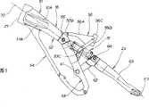
图5是表示本发明的车身架构造的侧面图。Fig. 5 is a side view showing the body frame structure of the present invention.
图6是表示本发明的车身架要部的侧面图。Fig. 6 is a side view showing essential parts of the vehicle body frame of the present invention.
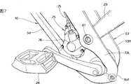
图7是表示本发明的车身架下部的立体图。Fig. 7 is a perspective view showing the lower part of the vehicle body frame of the present invention.
图8是本发明自行车的要部背面图。Fig. 8 is a rear view of main parts of the bicycle of the present invention.
具体实施方式Detailed ways
下面,参照附图说明本发明的实施方式。附图是按照标记的方向看的。Hereinafter, embodiments of the present invention will be described with reference to the drawings. The drawings are viewed in the direction indicated.
图1是采用本发明车身架配置构造的自行车的立体图。自行车10是下坡用的车辆,是在林间道路、滑雪场等的高速弯道、设有跳跃段的未铺装道路上行驶的用于竞时的比赛的车辆。在前轮11和后轮12,分别由前叉14、后缓冲单元15吸收来自路面的冲击,车身架16提高了刚性,支承大的荷载,另一方面,车身架16的一部分备有柔韧性,提高操纵性,另外,为了提高前轮11和后轮12的制动力,采用了盘形闸(后面详细说明)。Fig. 1 is a perspective view of a bicycle adopting the body frame arrangement structure of the present invention. The
图2是本发明自行车的侧面图。自行车10,在头管21上安装着可操纵方向的前叉14。在该前叉14的下端可旋转地安装着前轮11。在前叉14的上部安装着操纵手柄22。车身架16从头管21向后斜下方延伸,在该车身架16的后部可上下摆动地安装着L字形摆动臂23。在该摆动臂23的后端可旋转地安装着后轮12。后缓冲单元15架设在车身架16和摆动臂23上,在车身架16的后部安装着变速器25。在该变速器25的左右分别安装着踏板26、27,在车身架16的中间部安装着鞍座28。Fig. 2 is a side view of the bicycle of the present invention. In the
31是前轮用盘形闸(32是闸钳,33是闸盘),34、34(里侧的标记34图未示)是保护前叉14下部的前叉保护件,35是前挡泥板,36是用软管37连接在后缓冲单元15上的副油箱,38是安装在变速器25的输出轴上的驱动侧链轮,41是安装在后轮12上的被动侧链轮,42是链,43是后轮用盘形闸(44是闸钳,45是闸盘)。31 is a disc brake for the front wheel (32 is a brake caliper, and 33 is a brake disc), 34, 34 (the
图3是本发明中的车身架的立体图。车身架16由箱状的箱架部51、双管部52、后部架部53、下管54和鞍座架56(见图2)构成。箱架部51从头管21向后斜下方延伸。双管部52从箱架部51的后端左右分开,并朝后斜下方即在箱架部51的延长线上延伸。后部架部53从该双管部52的后端使其比箱架部51及双管部52的倾斜角更加倾斜地向后斜下方延伸。下管部54从箱架部51的前端下部向后斜下方延伸,并且与后部架53的后端连接。鞍座架56用于把鞍座28(见图2)安装到双管部52的后端及后部架部53的中间部。16A、16B是圆筒状的后端结合部,用左右用螺栓将后部架部53的后端和下管54的后端的连接部分结合。Fig. 3 is a perspective view of the vehicle body frame in the present invention. The
箱架部51是通过做成为箱状而使车身架16的前部成为高刚性的部分。The
双管部52分成左右的较细的管52L、52R,以减低刚性,是使车身架16的中央部容易扭曲的部分设后端内面,备有用于安装后缓冲单元15(见图2)前端的缓冲安装部52A、52A,在后端上部设有用于安装鞍座架56前部的鞍座架前部安装部52B、52B。The
后部架部53由于加大了左右宽度,容易收容变速器(见图2),并且,是提高了支承力的部分,该支承力支承作用在摆动臂23(见图2)的安装部上的扭曲,由左右架部53L、53R构成,在中间部内面具有用于安装摆动臂23前端的臂安装部53A、53B,在中间部上部设有用于安装鞍座架56后部的鞍座架后部安装部53C、53C。
下管54备有二股部54A和变速器安装孔54B、534B。二股部54A在后部支承变速器25,同时与后部架部53的后端连接,形成为二股叉状。变速器安装孔54B、54B开设在二股部54A的根部分,用于安装变速器25。54C、54C是构成二股部54A的弯曲状臂部。The down
在头管21的附近是高刚性的箱架部51,在后部架部53,在车宽方向扩开地安装摆动臂23的安装部,所以,对于来自后轮12(见图2)的扭矩具有高刚性。在箱架部51的后部架部53的约中间部,在车宽方向设有细的双管部52,这样,对于来自前后轮11、12(见图2)的大荷载,车身的中间部容易扭曲,车身的中间部成为包含驾驶者在内的重心附近,可提高操纵性。In the vicinity of the
图4是图4的3向视图。车身架16的各部的车宽方向外形尺寸(下面仅表示为“宽度”)是:在箱架部51是宽度B1,在双管部52是宽度B2,在后部架部53是宽度B3,B2<B1,B3>B2。Fig. 4 is a 3-direction view of Fig. 4 . The vehicle width direction external dimensions (hereinafter simply referred to as "width") of each part of the
即,使双管部52的宽度B2小于箱架部51的宽度B1及后部架部53的宽度B3,当驾驶者蹬踏板时,不容易碰到膝盖,不妨碍膝盖的动作,可进行良好的踏板操作。That is, if the width B2 of the
使后部架53的宽度B3大于双管部52的宽度B2,由此增大左右架部53L、53R间的空间SP,可容易地将变速器25(见图2)等部件收容在该空间SP内。By making the width B3 of the
另外,对于摆动臂23(见图2)的扭曲,通过加大宽度,可得到良好的后轮12(见图2)的摆动(后缓冲单元15(见图2)的伸缩)。In addition, with respect to twisting of the swing arm 23 (see FIG. 2 ), by increasing the width, good swing of the rear wheel 12 (see FIG. 2 ) (stretch of the rear buffer unit 15 (see FIG. 2 )) can be obtained.
图5是表示本发明中车身架构造的侧面图。摆动臂23是由立起部62、后部伸出部63构成的大致L字形部件。立起部62从安装在后部架部53上的枢轴61朝后斜上方延伸。后部伸出部63从该立起部62的上端朝后斜下方延伸。在立起部62与后部伸出部63的连接部安装着后缓冲单元15的后端安装轴64。65是设在双管部52上的安装轴,用于安装后缓冲单元15的前端。67是开设在后部伸出部63的后端的长孔,用于安装后轮12(见图2)的车轴。Fig. 5 is a side view showing the structure of the vehicle body frame in the present invention. The
由于把摆动臂23做成为上述的形状,在本发明的车身架构造中,可将箱架部51、双管部52、后缓冲单元15及后部伸出部63做成为大致直线状,即沿着直线70的形状。Since the
因此,可以把从后轮12通过摆动臂23、后缓冲单元15传递到箱架部51、双管部52的荷载作为大致轴向压荷载作用到箱架部51、双管部52上。Therefore, the load transmitted from the
这样,与已往那样的、从摆动臂传递到车身架的荷载作为弯曲荷载作用到车身架上相比,本发明中,可以用车身架16支承大的荷载。Thus, in the present invention, a large load can be supported by the
鞍座架56由上部架部56A、下部架部56B和圆筒部56C构成。上部架部56A安装在双管部52的鞍座架前部安装部52B、52B(里侧的鞍座架前部安装部52B图未示)上。下部架部56B安装在后部架部53的鞍座架后部安装部53C、53C上。圆筒部56C安装上部架部56A及下部架部56B的各端部。用圆筒部56C支承安装在鞍座28(见图2)下部的鞍座支柱28A(见图2)。The
这样,用鞍座架56全体覆盖后缓冲单元15的大致整个上方及侧方的一部分,可保护后缓冲单元15不受飞来的石子等碰撞。In this way, the
图6是表示本发明的车身架要部的侧视图。在车身架16的箱架部51的侧面上形成上下平行的、沿长度方向的横肋51A、51B。Fig. 6 is a side view showing essential parts of the vehicle body frame of the present invention.
这样,由于在箱架部51上设置横肋51A、51B,更加提高了箱架部51的刚性。因此,只要确保预定的刚性,可以进一步减薄箱架部51的厚度,可以使箱架部51更轻量化。In this way, since the
图7是表示本发明中车身架下部的立体图。在加宽了的后部架部53的内侧配置变速器25。Fig. 7 is a perspective view showing the lower part of the vehicle body frame in the present invention. The
变速器25,是通过钢丝绳75与设在操纵手柄22(见图2)上的变速用杆(图未示)连接的装置。通过操作上述的变速用杆,拉动与该变速用杆连接着的钢丝绳75,使连接着该钢丝绳75的端部的连接部76动作,变更踏板26、27(踏板27图未示)的旋转轴即踏板轴与输出轴之间的齿轮比,该输出轴一体地安装在驱动侧链轮38(见图2)上。The
图8是本发明自行车的要部背面图。用从连接部78延伸的左右臂部63L、63R,构成摆动臂23的后部伸出部63,该连接部78与立起部62(见图5)连接。Fig. 8 is a rear view of main parts of the bicycle of the present invention. The
这样,连接部78由于连接左右的臂部63L、63R,是提高了刚性的部分,把后缓冲单元15的后端连接在该连接部78上,由此可有效地将荷载从后轮12通过后部伸出部63传递到后缓冲单元15。In this way, the connecting portion 78 is a portion with increased rigidity due to connecting the left and right arm portions 63L, 63R, and the rear end of the
如上面图1、图3和图4所述,本发明第1方案的的自行车用车身架构造,在自行车10中,在车身架16的前部通过前叉14可转向地安装着的前轮11,在车身架16的后部可上下摆动地安装着摆动臂23,在该摆动臂23的后端安装着后轮12,上述车身架16由头管21、箱形的箱架部51、双管部52和后部架部53构成。头管21上可旋转地安装着前叉14;箱架部51从头管21朝后斜下方延伸。双管部52从箱架部51的后端左右分开并朝后斜下方延伸,并且在车宽方向比箱架部51缩窄。后部架部53从双管部52的各后端朝后斜下方延伸,并且在车宽方向比双管部52增宽。1, 3 and 4 above, in the bicycle body frame structure of the first aspect of the present invention, in the
在头管21附近,把车身架16做成为箱状的箱架部51,成为高刚性部分,可用箱架部51支承从路面通过前轮11、前叉14传递到头管21的大荷载,同时,在作为摆动臂23的安装部的后部架部53加大宽度,所以,可抑制由作用在后轮12上的荷载引起的摆动臂23的扭曲。In the vicinity of the
另外,在位于大致中间部的双管部52(低刚性部)使其产生扭曲,在重心附近变形,由此可提高自行车10的操纵性。In addition, by twisting the double pipe portion 52 (low rigidity portion) located approximately in the middle, and deforming near the center of gravity, the steerability of the
另外,使双管部52的宽度B2比箱架部51的宽度B1及后部架部53的宽度B3窄,这样,驾驶者在蹬踏板26、27时,不妨碍膝盖的运动,可进行良好的踏板操作,提高运转性。In addition, the width B2 of the
另外,由于将后部架部53的宽度B3加宽,可加大左右后部架部53间的空间SP,可提高该空间SP对变速机25等部件的收容性。另外,可抑制摆动臂23的扭曲。In addition, since the width B3 of the
本发明第2方案的自行车用车身架构造,其特征在于,在后部架部53的大致中间部具有作为摆动臂23的安装部的枢轴61。The bicycle body frame structure according to the second aspect of the present invention is characterized in that the
由于把摆动臂23安装在车宽方向宽的后部架部53上,所以,可用间隔大的2个支点承受从摆动臂23传递到后部架部53上的扭矩,这样,可以减小由该扭矩产生的荷载,如果这样地减小了作用在后部架部53上的荷载,就可以减小后部架部53的摆动臂安装部的刚性,可抑制后部架部53的重量增加。Since the
本发明第3方案的自行车用车身架构造,其特征在于,摆动臂23是大致L字形的部件,由从枢轴61朝后斜上方延伸的立起部62和从该立起部62上端朝后斜下方延伸的后部伸出部63构成,在车身架16的双管部52的后端通过后缓冲单元15连接立起部62与后部伸出部63的连接部78,把箱架部51、双管部52、后缓冲单元15及后部伸出部63配置在大致一直线上,上述后缓冲单元15缓和从后轮12传递到车身架16上的冲击。The body frame structure for a bicycle according to the third aspect of the present invention is characterized in that the
由于把箱架部51、双管部52、后缓冲单元15及后部伸出部63配置在大致一直线上,所以,可以把从摆动臂23通过后缓冲单元15传递到箱架部51、双管部52的荷载作为轴向压缩荷载作用到箱架部51、双管部52,例如,与从摆动臂传递到车身架的荷载作为弯曲荷载作用时相比,本发明中,可以用车身架16支承更大的荷载。Since the
因此,一方面用上述箱架部51提高车身架16的刚性,同时,另一方面通过变更作用在车身架16上的荷载的方向,两者相结合可用车身架16承受来自前轮11和后轮12的更大的荷载,所以,对车身架16赋予规定大小的刚性时,可以进一步减小车身架16的厚度,实现轻量化,减轻自行车10的重量。Therefore, on the one hand, the rigidity of the
结果,可提高自行车10的运动性能,在路况差的道路上行驶时,可减轻自行车10各部的损害,提高耐久性。As a result, the sports performance of the
本发明第4方案的自行车用车身架构造,其特征在于,在双管部52的后端和后部架部53上安装用于支承鞍座28的鞍座架56,在该鞍座架56的下方配置后缓冲单元15。The bicycle body frame structure of the fourth aspect of the present invention is characterized in that a
由于在鞍座架56的下方配置后缓冲单元15,所以,后缓冲单元15被覆盖其整个上方及侧方的一部分的鞍座架56和覆盖其侧方下方的后部架部53围住,可防止飞石子碰撞到后缓冲单元15。Since the
本发明的自行车用车身架构造,并不限定于自行车,也可以在机动两轮车、尤其是在越野用车辆上采用。The body frame structure for bicycles of the present invention is not limited to bicycles, but can also be employed in motorcycles, especially off-road vehicles.
发明效果Invention effect
本发明具有以下效果。The present invention has the following effects.
权利要求1记载的自行车用车身架构造,车身架由头管、箱形的箱架部、双管部和后部架部构成;头管上可旋转地安装着前叉;箱架部从头管朝后斜下方延伸;双管部从箱架部的后端左右分开并朝后斜下方延伸,并且在车宽方向比箱架部变窄;后部架部从双管部的各后端朝后斜下方延伸,并且在车宽方向比双管部增宽,在头管附近,把车身架做成为箱状的箱架部,作为高刚性部分,在双管部,将车身架左右较细地分开,作为低刚性部分,这样,可用箱架部支承从路面通过前轮、前叉传递到头管的大荷载,同时,在车身中心部容易产生扭曲,可提高车辆的操纵性。The bicycle body frame structure described in claim 1, the body frame is composed of a head tube, a box-shaped box frame part, a double tube part and a rear frame part; the front fork is rotatably installed on the head tube; The rear extends obliquely downward; the double pipe part is separated left and right from the rear end of the box frame part and extends toward the rear diagonally downward, and is narrower than the box frame part in the vehicle width direction; the rear frame part is rearward from each rear end of the double pipe part It extends obliquely downward, and is wider than the double pipe part in the vehicle width direction. The body frame is made into a box-shaped box frame part near the head pipe. Separated, as a low-rigidity part, in this way, the box frame can support the large load transmitted from the road to the head tube through the front wheel and front fork, and at the same time, it is easy to twist in the center of the body, which can improve the maneuverability of the vehicle.
权利要求2记载的自行车用车身架构造,在后部架部的约中间部具有摆动臂的安装部。由于把摆动臂安装在车宽方向宽的后部架部上,所以,可用间隔大的2个支点承受从摆动臂传递到后部架部上的扭矩,这样,可以减小由该扭矩产生的荷载,如果这样地减小了作用在后部架部上的荷载,则就可以减小后部架部的摆动臂安装部的刚性,可抑制后部架部的重量增加。The body frame structure for a bicycle according to claim 2, wherein a swing arm attachment portion is provided approximately in the middle of the rear frame portion. Since the swing arm is installed on the rear frame part wide in the vehicle width direction, the torque transmitted from the swing arm to the rear frame part can be received by two fulcrums with large intervals, so that the torque generated by the torque can be reduced. If the load acting on the rear frame portion is reduced in this way, the rigidity of the swing arm mounting portion of the rear frame portion can be reduced, and an increase in the weight of the rear frame portion can be suppressed.
另外,由于对扭曲有利,所以,可得到良好的摆动臂的摆动(缓冲单元的伸缩)。In addition, since twisting is advantageous, favorable swinging of the swinging arm (expansion and contraction of the buffer unit) can be obtained.
权利要求3记载的自行车用车身架构造,摆动臂是大致L字形的部件,由从后部架部具有的安装部朝后斜上方延伸的立起部、和从该立起部的上端朝后斜下方延伸的后部伸出部构成,在车身架的双管部的后端通过后缓冲单元连接立起部与后部伸出部的连接部,把箱架部、双管部、后缓冲单元及后部伸出部配置在大致一直线上,上述后缓冲单元缓和从后轮传递到车身架上的冲击。由于把箱架部、双管部、后缓冲单元及后部伸出部配置在大致一直线上,所以,可以把从摆动臂通过缓冲单元传递到箱架部、双管部的荷载作为轴向压缩荷载作用到箱架部、双管部,例如,与从摆动臂传递到车身架的荷载作为弯曲荷载作用时相比,可以用车身架支承更大的荷载。The body frame structure for a bicycle according to claim 3, wherein the swing arm is a substantially L-shaped member, and consists of an upright portion extending obliquely upward from the mounting portion of the rear frame portion, and a rearward portion from the upper end of the upright portion. The rear extension part extending obliquely downward is composed of the rear end of the double pipe part of the body frame. The unit and the rear protruding portion are arranged on a substantially straight line, and the rear shock absorber unit cushions the shock transmitted from the rear wheel to the body frame. Since the frame part, double pipe part, rear buffer unit, and rear extension part are arranged on a substantially straight line, the load transmitted from the swing arm to the frame part and double pipe part through the buffer unit can be regarded as the axial direction. The compressive load acts on the box frame portion and the double pipe portion, for example, the body frame can support a larger load than when the load transmitted from the swing arm to the body frame acts as a bending load.
权利要求4记载的自行车用车身架构造,在双管部的后端和后部架部上安装用于支承鞍座的鞍座架,在该鞍座架的下方配置上述的后缓冲单元。所以,后缓冲单元被鞍座架和后部架部围住,可防止飞石子碰撞到后缓冲单元。In the body frame structure for a bicycle according to
Claims (2)
Translated fromChineseApplications Claiming Priority (2)
| Application Number | Priority Date | Filing Date | Title |
|---|---|---|---|
| JP2002119426AJP4116812B2 (en) | 2002-04-22 | 2002-04-22 | Body frame structure for bicycles |
| JP119426/2002 | 2002-04-22 |
Publications (2)
| Publication Number | Publication Date |
|---|---|
| CN1453176A CN1453176A (en) | 2003-11-05 |
| CN1305729Ctrue CN1305729C (en) | 2007-03-21 |
Family
ID=28786746
Family Applications (1)
| Application Number | Title | Priority Date | Filing Date |
|---|---|---|---|
| CNB03108429XAExpired - Fee RelatedCN1305729C (en) | 2002-04-22 | 2003-03-31 | Frame structure of bicycle |
Country Status (7)
| Country | Link |
|---|---|
| US (1) | US6979014B2 (en) |
| EP (1) | EP1357022B8 (en) |
| JP (1) | JP4116812B2 (en) |
| CN (1) | CN1305729C (en) |
| DE (1) | DE60301224T2 (en) |
| ES (1) | ES2246434T3 (en) |
| TW (1) | TW576817B (en) |
Families Citing this family (9)
| Publication number | Priority date | Publication date | Assignee | Title |
|---|---|---|---|---|
| JP4494034B2 (en)* | 2004-02-10 | 2010-06-30 | 本田技研工業株式会社 | Transmission cable arrangement structure |
| US7644795B2 (en)* | 2005-06-17 | 2010-01-12 | Kawasaki Jukogyo Kabushiki Kaisha | Vehicle body structure of motorcycle |
| US8857841B2 (en)* | 2011-01-05 | 2014-10-14 | Trek Bicycle Corporation | Bicycle frame with passive seat tube pivot joint |
| US8757651B1 (en) | 2013-03-14 | 2014-06-24 | Patrick A. Walker | Collapsible motorized two-wheeled cycle system |
| ES2708818T3 (en)* | 2015-05-17 | 2019-04-11 | Trek Bicycle Corp | Adjustable handling bike |
| CN105947077A (en)* | 2016-06-29 | 2016-09-21 | 何响明 | Bicycle frame structure |
| CN105947078B (en)* | 2016-06-29 | 2019-03-12 | 何响明 | A kind of body frame structure for automotive |
| US10316951B2 (en) | 2016-07-13 | 2019-06-11 | Shimano Inc. | Bicycle drive unit |
| CA3015256A1 (en)* | 2018-08-24 | 2020-02-24 | Clark A. Wallace | Bicycle frame assembly |
Citations (5)
| Publication number | Priority date | Publication date | Assignee | Title |
|---|---|---|---|---|
| US4094375A (en)* | 1975-04-03 | 1978-06-13 | Agence Nationale De Valorisation De La Recherche (Anvar) | Rigid connection device and its application to motor cycles |
| GB2117333A (en)* | 1982-03-25 | 1983-10-12 | Tekton | Bicycle frames |
| US4753314A (en)* | 1986-04-07 | 1988-06-28 | Honda Giken Kogyo Kabushiki Kaisha | Attachment structure for rear wheel damper of motorcycle |
| JPH0211484A (en)* | 1988-06-28 | 1990-01-16 | Honda Motor Co Ltd | Motorcycle ventilation structure |
| CN1038664C (en)* | 1993-01-16 | 1998-06-10 | 采矿企业有限公司 | Bike suspension |
Family Cites Families (13)
| Publication number | Priority date | Publication date | Assignee | Title |
|---|---|---|---|---|
| DE407969C (en)* | 1923-11-15 | 1925-01-06 | Friedrich Emil Krauss | Support frame for motorcycles |
| US2280801A (en)* | 1938-09-06 | 1942-04-28 | Sears Roebuck & Co | Bicycle construction |
| JPS55123580A (en)* | 1979-03-19 | 1980-09-24 | Yamaha Motor Co Ltd | Frame of twoowheel barrow |
| JPS55156775A (en)* | 1979-05-26 | 1980-12-06 | Honda Motor Co Ltd | Motorcycle |
| FR2480699A1 (en)* | 1980-04-18 | 1981-10-23 | Lebaron Richard | Motorcycle frame swing arm mounting - has pivot axis coinciding with that of engine output shaft |
| JPS62238180A (en)* | 1986-04-07 | 1987-10-19 | 本田技研工業株式会社 | Frame structure of motorcycles, etc. |
| EP0322305B1 (en)* | 1987-12-21 | 1994-04-06 | Honda Giken Kogyo Kabushiki Kaisha | Body frame for motor-bicycle |
| JPH0214989A (en)* | 1989-05-16 | 1990-01-18 | Yamaha Motor Co Ltd | Frame for motorcycle |
| JP2903648B2 (en) | 1990-06-08 | 1999-06-07 | いすゞ自動車株式会社 | Control unit for diesel engine |
| JPH09263282A (en) | 1996-03-29 | 1997-10-07 | Bridgestone Cycle Co | Bicycle frame with shock absorber |
| US5911429A (en)* | 1997-04-11 | 1999-06-15 | Giant Manufacturing Co., Ltd | Bicycle frame |
| US6871867B2 (en)* | 2000-12-19 | 2005-03-29 | Greg M. Parigian | Multi-linking, rear suspension system for two-wheeled motor vehicles |
| US20040061305A1 (en)* | 2002-09-30 | 2004-04-01 | Christini Steven J. | Rear wheel suspension system for a bicycle |
- 2002
- 2002-04-22JPJP2002119426Apatent/JP4116812B2/ennot_activeExpired - Fee Related
- 2003
- 2003-03-20ESES03006368Tpatent/ES2246434T3/ennot_activeExpired - Lifetime
- 2003-03-20EPEP03006368Apatent/EP1357022B8/ennot_activeExpired - Lifetime
- 2003-03-20DEDE60301224Tpatent/DE60301224T2/ennot_activeExpired - Lifetime
- 2003-03-25TWTW092106654Apatent/TW576817B/ennot_activeIP Right Cessation
- 2003-03-31USUS10/401,787patent/US6979014B2/ennot_activeExpired - Fee Related
- 2003-03-31CNCNB03108429XApatent/CN1305729C/ennot_activeExpired - Fee Related
Patent Citations (5)
| Publication number | Priority date | Publication date | Assignee | Title |
|---|---|---|---|---|
| US4094375A (en)* | 1975-04-03 | 1978-06-13 | Agence Nationale De Valorisation De La Recherche (Anvar) | Rigid connection device and its application to motor cycles |
| GB2117333A (en)* | 1982-03-25 | 1983-10-12 | Tekton | Bicycle frames |
| US4753314A (en)* | 1986-04-07 | 1988-06-28 | Honda Giken Kogyo Kabushiki Kaisha | Attachment structure for rear wheel damper of motorcycle |
| JPH0211484A (en)* | 1988-06-28 | 1990-01-16 | Honda Motor Co Ltd | Motorcycle ventilation structure |
| CN1038664C (en)* | 1993-01-16 | 1998-06-10 | 采矿企业有限公司 | Bike suspension |
Also Published As
| Publication number | Publication date |
|---|---|
| TW200305523A (en) | 2003-11-01 |
| JP4116812B2 (en) | 2008-07-09 |
| DE60301224D1 (en) | 2005-09-15 |
| DE60301224T2 (en) | 2006-03-23 |
| EP1357022B8 (en) | 2005-10-12 |
| CN1453176A (en) | 2003-11-05 |
| EP1357022A2 (en) | 2003-10-29 |
| EP1357022A3 (en) | 2004-09-29 |
| TW576817B (en) | 2004-02-21 |
| JP2003312575A (en) | 2003-11-06 |
| ES2246434T3 (en) | 2006-02-16 |
| US6979014B2 (en) | 2005-12-27 |
| EP1357022B1 (en) | 2005-08-10 |
| US20030227156A1 (en) | 2003-12-11 |
Similar Documents
| Publication | Publication Date | Title |
|---|---|---|
| US8434776B2 (en) | Bicycle frame with rear suspension system | |
| CN1091046C (en) | Battery container structure for motor bicycle | |
| US20060197306A1 (en) | Bicycle with rear suspension | |
| US20080054595A1 (en) | Bicycle frame with a counter-rotating four bar linkage system | |
| CN1939802A (en) | motorized two-wheeler | |
| CN1956876A (en) | Bicycle Suspension Components | |
| CN1305729C (en) | Frame structure of bicycle | |
| CN1283519C (en) | Front wheel fork structure for cycle | |
| US8051739B2 (en) | Vehicle-use transmission manipulating device | |
| FR2789360A1 (en) | WHEEL VEHICLE WHOSE DRIVE WHEEL AXLE IS CARRIED BY A SWING ARM AND WHOSE MOTOR TORQUE IS TRANSMITTED TO THE DRIVE WHEEL BY CHAIN AND SPROCKETS | |
| CN1503746A (en) | Rear suspension of vehicle with drive wheel supported by swing arm | |
| JP2003206962A (en) | Braking device for saddle type off-road running vehicle | |
| CN1297437C (en) | Body structure of saddle-type motorcycle | |
| CN1895959A (en) | Electric bicycle | |
| GB2454021A (en) | Bicycle with rear suspension system | |
| CN103863496A (en) | Front wheel supporting structure for vehicle | |
| CN1229248C (en) | bicycle saddle | |
| CN1621303A (en) | Brake device for motor tricycle | |
| CN1740031A (en) | Occupant restraint device for two-wheeled vehicles | |
| CN1923599A (en) | two-wheeled motor vehicle | |
| CN1388035A (en) | Rear-swing arm for motor bicycle | |
| CN100344474C (en) | Exhauster for mopeds | |
| US20250256808A1 (en) | Routing pulley to limit virtual chain growth in geared rear suspension bicycles | |
| US20240017790A1 (en) | Rear suspension for two-wheeled vehicle | |
| US20240132178A1 (en) | Fork arch |
Legal Events
| Date | Code | Title | Description |
|---|---|---|---|
| C06 | Publication | ||
| PB01 | Publication | ||
| C10 | Entry into substantive examination | ||
| SE01 | Entry into force of request for substantive examination | ||
| C14 | Grant of patent or utility model | ||
| GR01 | Patent grant | ||
| C17 | Cessation of patent right | ||
| CF01 | Termination of patent right due to non-payment of annual fee | Granted publication date:20070321 Termination date:20140331 |