CN1305648C - manipulator - Google Patents
manipulatorDownload PDFInfo
- Publication number
- CN1305648C CN1305648CCNB028022599ACN02802259ACN1305648CCN 1305648 CCN1305648 CCN 1305648CCN B028022599 ACNB028022599 ACN B028022599ACN 02802259 ACN02802259 ACN 02802259ACN 1305648 CCN1305648 CCN 1305648C
- Authority
- CN
- China
- Prior art keywords
- brake
- mechanical arm
- manipulator
- movement
- release
- Prior art date
- Legal status (The legal status is an assumption and is not a legal conclusion. Google has not performed a legal analysis and makes no representation as to the accuracy of the status listed.)
- Expired - Fee Related
Links
Images


Classifications
- B—PERFORMING OPERATIONS; TRANSPORTING
- B25—HAND TOOLS; PORTABLE POWER-DRIVEN TOOLS; MANIPULATORS
- B25J—MANIPULATORS; CHAMBERS PROVIDED WITH MANIPULATION DEVICES
- B25J9/00—Programme-controlled manipulators
- B25J9/10—Programme-controlled manipulators characterised by positioning means for manipulator elements
- B—PERFORMING OPERATIONS; TRANSPORTING
- B25—HAND TOOLS; PORTABLE POWER-DRIVEN TOOLS; MANIPULATORS
- B25J—MANIPULATORS; CHAMBERS PROVIDED WITH MANIPULATION DEVICES
- B25J9/00—Programme-controlled manipulators
- B25J9/16—Programme controls
- B25J9/1674—Programme controls characterised by safety, monitoring, diagnostic
- G—PHYSICS
- G05—CONTROLLING; REGULATING
- G05B—CONTROL OR REGULATING SYSTEMS IN GENERAL; FUNCTIONAL ELEMENTS OF SUCH SYSTEMS; MONITORING OR TESTING ARRANGEMENTS FOR SUCH SYSTEMS OR ELEMENTS
- G05B2219/00—Program-control systems
- G05B2219/30—Nc systems
- G05B2219/40—Robotics, robotics mapping to robotics vision
- G05B2219/40218—Check conditions before allowing unlocking of joint brake
Landscapes
- Engineering & Computer Science (AREA)
- Robotics (AREA)
- Mechanical Engineering (AREA)
- Manipulator (AREA)
- Braking Arrangements (AREA)
- Control Of Position Or Direction (AREA)
Abstract
Description
Translated fromChinese技术领域technical field
本发明涉及一种机械手控制装置的改进,该控制装置释放机械手的手机械手臂的制动器,使伺服系统为停止控制的状态。The invention relates to an improvement of a control device of a manipulator. The control device releases the brake of the mechanical arm of the manipulator, so that the servo system is in the state of stopping control.
背景技术Background technique
机械手作为省力、省人用的输送和安装装置,已建立牢固的地位,一直在汽车生产、家电生产、半导体生产等制造业领域作多种用途。尤其是制动器释放技术使机械手的机械手臂移动到搬运时的姿势,从而具有减小包装容积的效果,还具有在因移动到行程范围外而不能控制时进行还原操作的效果,成为机械手的基本技术。As a labor-saving and labor-saving conveying and installation device, the manipulator has established a solid position and has been used for various purposes in the manufacturing fields such as automobile production, home appliance production, and semiconductor production. In particular, the brake release technology enables the robot arm to move to the posture during transportation, which has the effect of reducing the packaging volume, and also has the effect of restoring operation when it is out of the stroke range and cannot be controlled. It has become the basic technology of the robot. .
图16是日本国专利公开平11-179691号公报所揭示用于释放制动器的已有生产用机械手控制装置的框图,图17是制动控制流程图,图18是示出制动器动作的状态图。Fig. 16 is a block diagram of a conventional production manipulator control device for releasing the brake disclosed in Japanese Patent Publication No. Hei 11-179691, Fig. 17 is a flow chart of braking control, and Fig. 18 is a state diagram showing the operation of the brake.
下面,说明其组成。上述图中,1是机械手主体,每一关节具有电机11、位置检测器12、制动器组13。2是控制装置,利用工作程序对机械手主体1进行驱动控制,并且具有中央处理装置21、伺服控制部23、伺服放大部24、制动器控制部25、制动器驱动部26。3是手动操作装置,用于使操作者提供机械手控制所需的指令。Next, its composition will be described. In the above figure, 1 is the main body of the manipulator, each joint has a motor 11, a position detector 12, and a brake group 13. 2 is the control device, which uses the working program to drive and control the main body of the
控制装置2中的中央处理装置21是根据控制程序产生机械手主体1的位置控制和各种功能的指令的部分。伺服控制部23、伺服放大部24和电机11构成伺服控制系统。对伺服系统进行控制时,给伺服控制部23提供有关移动或停止的指令,还将该指令传给伺服放大部24,最后在电机11产生驱动机械手臂(图中未示出)的旋转力,无移动指令时,与机构手机械手臂本身的重量平衡,从而停止。有移动指令时,构成产生大于抵消机械手臂本身重量的旋转力,使机械手臂移动。The central processing unit 21 in the
电机11中装有位置检测器12。位置检测器12识别机械手臂的伺服控制位置,构成实际检测出电极11的旋转角度,将其输出信号反馈给伺服控制部23和伺服放大部24,从而使机械手臂经常保持来自操作部3的位置指令值。制动器13与电机11的轴合为一体,或装在该轴与机械手臂之间。27是制动器释放时间设定部,28是制动器制动时间设定部。制动器释放时间设定部27和制动器制动时间设定部28构成在中央处理装置21的存储器(图中未示出)分配为机械手控制装置的参数,能由操作者从手动操作装置3等进行变换。制动器驱动部26根据制动器控制部25的输出信号进行驱动,使制动器13实际释放或制动。结构上做成利用按压手动操作装置3中存在的释放操作开关(未示出)产生制动器13的释放指令。A position detector 12 is installed in the motor 11 . The position detector 12 recognizes the servo control position of the robot arm, constitutes the actual detection of the rotation angle of the electrode 11, and feeds back the output signal to the servo control part 23 and the servo amplifier part 24, so that the robot arm always maintains the position from the operation part 3 instruction value. The brake 13 is integrated with the shaft of the motor 11, or is installed between the shaft and the mechanical arm. 27 is a brake release time setting part, and 28 is a brake application time setting part. The brake release time setting part 27 and the brake braking time setting part 28 constitute a memory (not shown) in the central processing unit 21 that is distributed as a parameter of the manipulator control device, which can be performed by the operator from the manual operation device 3 or the like. transform. The brake drive unit 26 is driven based on the output signal of the brake control unit 25 to actually release or brake the brake 13 . Structurally, a release command of the brake 13 is generated by pressing a release operation switch (not shown) present in the manual operation device 3 .
下面,说明其动作。首先,在步骤S71,中央处理装置21判断手动操作装置3中释放操作开关的工作状态。制动器释放指令的释放操作开关为“导通”时,进至步骤S72,中央处理装置21进行伺服系统的控制停止处理。即,进行制动器13的制动动作,停止对伺服控制部23、伺服放大部24和电机11输出信号,由制动器13使机械手臂停止。接着,步骤S73中,制动器控制部25从制动器释放时间设定部27读出释放时间数据,将信号输出到制动器驱动部26,以便仅在符合制动时间数据的时间使制动器13进行制动。制动时间过后,返回到步骤S71,判断释放操作开关的工作状态。结果,如图18所示,在操作者连续按压手动操作装置3的释放操作开关的期间,根据各自的时间数据进行制动器13的释放和制动动作。Next, the operation thereof will be described. First, in step S71 , the central processing unit 21 judges the working state of the release operation switch in the manual operation device 3 . When the release operation switch of the brake release command is "on", the process proceeds to step S72, and the central processing unit 21 performs control stop processing of the servo system. That is, the braking operation of the brake 13 is performed, the output of signals to the servo control unit 23 , the servo amplifier 24 and the motor 11 is stopped, and the robot arm is stopped by the brake 13 . Next, in step S73, the brake control unit 25 reads the release time data from the brake release time setting unit 27, and outputs a signal to the brake drive unit 26 to brake the brake 13 only at a time corresponding to the braking time data. After the braking time, return to step S71 to judge the working state of the release operation switch. As a result, as shown in FIG. 18 , while the operator continues to press the release operation switch of the manual operation device 3 , the release and braking operations of the brake 13 are performed based on the respective time data.
不按压释放操作开关(阻断)时,进至步骤S75的处理,进行该处理,判断伺服系统是否正在控制后,返回步骤S71。结果,伺服系统正在控制时,常使制动器13的释放状态继续。步骤S75中,在伺服控制运作中以外的状态下,进行步骤S77的使制动器13进行制动的处理后,返回步骤S71,判断释放操作开关的工作状态。When the release operation switch is not pressed (blocked), proceed to the processing of step S75, perform this processing, determine whether the servo system is being controlled, and then return to step S71. As a result, the released state of the brake 13 is often continued while the servo system is in control. In step S75, when the servo control is not in operation, the process of braking the brake 13 in step S77 is performed, and then returns to step S71 to determine the operating state of the release operation switch.
如以上说明那样,已有的机械手预先设定制动器的释放时间和制动时间,根据该设定时间重复进行制动器13的制动和释放过程,因而制动器释放时的手机械手臂移动速度很大程序上依赖于其重量、姿势和负荷等。As explained above, the existing manipulator pre-sets the release time and braking time of the brake, and repeats the braking and releasing process of the brake 13 according to the set time, so the moving speed of the manipulator arm when the brake is released is very high. depends on its weight, posture and load etc.
例如,从要使制动器放开的关节的旋转中心看,机械手臂的重量和负荷等的合成重心在大致水平位置时,关节旋转的转矩最大,从而旋转加速度也最大,使释放制动器时,机械手臂的移动速度急剧增加。For example, when viewed from the center of rotation of the joint where the brake is to be released, when the combined center of gravity of the weight and load of the robot arm is approximately horizontal, the rotational torque of the joint is the largest, and the rotational acceleration is also the largest, so that when the brake is released, the mechanical The movement speed of the arm increases dramatically.
从关节的旋转中心看,重心处于大致垂直位置时,关节旋转的转矩接近零,即使释放制动器,也因存在关节部的摩擦,如果操作者不加力,则处于机械手臂不开时移动的状态。Seen from the rotation center of the joint, when the center of gravity is in a roughly vertical position, the torque of the joint rotation is close to zero. Even if the brake is released, due to the friction of the joint, if the operator does not apply force, the robot arm will move when it is not open. state.
这样,已有的机械手根据机械手臂的重量、姿势和负荷条件等,释放制动器时的机械手臂移动速度急剧变化,因而操作者需要一面监视机械手臂的移动,一面调整制动器的制动和释放的时间。In this way, in the existing manipulator, the moving speed of the manipulator when the brake is released changes rapidly depending on the weight, posture, and load conditions of the manipulator, so the operator needs to monitor the movement of the manipulator while adjusting the braking and releasing time of the brake. .
而且,在释放制动器时,机械手臂不移动的状态下,操作者需要进行用手加力,使机械手臂移动等操作,还需要进行释放操作开关的操作,一个人难以进行作业。Moreover, when the brake is released and the robot arm does not move, the operator needs to apply force by hand to move the robot arm, and also needs to release the operation switch, so it is difficult for one person to work.
发明概要Summary of the invention
本发明是为解决上述问题而完成的,其目的为取得一种机械手,即使机械手臂的形状、姿势和负荷条件变化时,利用控制制动器,使制动器释放时的机械手臂移动速度、控制程序执行周期内的机械手臂移动量为一定值以内,也能抑制机械手臂的高速移动。The present invention has been made to solve the above problems, and its purpose is to obtain a manipulator that, even when the shape, posture and load conditions of the manipulator change, uses the control brake to make the manipulator movement speed and control program execution cycle when the brake is released. The movement amount of the robot arm within a certain value can also suppress the high-speed movement of the robot arm.
本发明的目的还在于得到一种机械手,利用进行制动器控制,使制动器释放时的机械手臂的移动速度和控制程序执行周期内的机械手臂的移动量在上限值与下限值之间,即使机械手臂的形状和姿势以及负荷条件变化时,也能抑制机械手臂地高速移动。The object of the present invention is also to obtain a kind of manipulator, utilize brake control, make the movement speed of manipulator arm when brake is released and the movement amount of manipulator arm in control program execution cycle be between upper limit value and lower limit value, even if Even when the shape and posture of the robot arm and the load conditions change, the high-speed movement of the robot arm can be suppressed.
本发明的目的还在于得到一种机械手,在多关节机械手那样因机械手姿势而关节旋转的旋转转矩不足,使机械手臂不移动时,或在正交型机械手的移动轴大致水平配置,即使设制动器释放,利用重力也不使机械手臂移动时,机械手臂都能移动;本发明的目的又在于得到一种机械手,在即使用机械手臂等的本身重量使移动开始后,移动速度和控制程序执行周期内的机械手臂的移动量达到一定值的情况下,进行制动器控制,抑制机械手臂的高速移动。Another object of the present invention is to obtain a manipulator. When the rotation torque of the joint rotation is insufficient due to the posture of the manipulator, such as a multi-joint manipulator, when the manipulator does not move, or when the moving axis of the orthogonal manipulator is arranged approximately horizontally, even if it is set When the brake is released and the mechanical arm is not moved due to gravity, the mechanical arm can move; the purpose of the present invention is to obtain a mechanical arm. When the movement amount of the robot arm inside reaches a certain value, the brake control is performed to suppress the high-speed movement of the robot arm.
本发明的目的还在于得到一种机械手,其中预先存储与机械手臂的姿势和负荷条件对应的制动器释放时间和制动器制动时间,并从姿势和负荷条件读出最佳制动器释放时间和制动器制动时间,根据这些时间控制制动器,从而可抑制机械手臂的高速移动。It is also an object of the present invention to obtain a manipulator in which the brake release time and brake application time corresponding to the posture and load conditions of the robot arm are stored in advance, and the optimum brake release time and brake application time are read out from the posture and load conditions. Time, and the brake is controlled according to these times, so that the high-speed movement of the robot arm can be suppressed.
本发明的目的在于得到一种机械手,能将机械手前端部位工作点的移动速度和控制程序执行周期内的工作点移动量控制为规定值。The object of the present invention is to obtain a manipulator capable of controlling the moving speed of the working point at the front end of the manipulator and the moving amount of the working point within the execution period of the control program to a predetermined value.
本发明所涉及的机械手在将伺服系统作为控制停止状态,进行机械手臂的制动器释放时,利用位置检测器检测出机械手臂的位置,根据移动位置和经过时间的位置变化量计算机械手臂的实际移动速度,将该实际移动速度与容许移动速度比较,把制动器的制动信号或释放信号送到驱动装置,从而进行制动器释放放或制动,将机械手臂的移动速度控制在规定值以内。The manipulator according to the present invention uses the position detector to detect the position of the manipulator when the brake of the manipulator is released using the servo system as the control stop state, and calculates the actual movement of the manipulator based on the moving position and the amount of position change over time. Speed, compare the actual moving speed with the allowable moving speed, send the braking signal or release signal of the brake to the drive device, so as to release or brake the brake, and control the moving speed of the robot arm within the specified value.
而且,本发明的机械手设定机械手臂的移动速度上限值和下限值,在实际移动速度超过上限值时,使制动器制动,低于下限值,则使制动器释放,并且在上限值与下限值之间控制机械手臂的移动速度。Moreover, the manipulator of the present invention sets the upper limit value and the lower limit value of the moving speed of the mechanical arm. When the actual moving speed exceeds the upper limit value, the brake is braked, and the brake is released when the actual moving speed exceeds the lower limit value, and the upper limit value Control the movement speed of the robot arm between the limit value and the lower limit value.
又,本发明的机械手在进行制动器释放时,利用位置检测器检测出机械手臂的移动位置,求出制动器释放程序执行周期中进行移动的机械手臂的移动量,将该移动量与设定的移动量比较,以控制制动器的制动和释放。Also, when the manipulator of the present invention releases the brake, the position detector is used to detect the movement position of the manipulator arm, and the movement amount of the manipulator arm that moves during the execution period of the brake release program is obtained, and the movement amount is compared with the set movement amount. Quantity comparison to control the braking and release of the brake.
又,本发明的机械手设置电机驱动辅助开关,在该开关“导通”时,使制动器释放,按规定方向对电机进行旋转驱动,直到达到机械手臂的容许移动速度后,将机械手臂的移动速度控制为规定值以内。In addition, the manipulator of the present invention is provided with a motor-driven auxiliary switch. When the switch is "on", the brake is released, and the motor is rotated and driven in a specified direction until it reaches the allowable moving speed of the manipulator. controlled within the specified value.
本发明预先存储与机械手臂的姿势和负荷条件对应的制动器释放时间和制动器制动时间,并从姿势和负荷条件读出最佳制动器释放时间和制动器制动时间,根据这些时间控制制动器。The present invention stores in advance the brake release time and brake application time corresponding to the posture and load conditions of the robot arm, reads out the optimal brake release time and brake application time from the posture and load conditions, and controls the brakes based on these times.
又,从到设定的机械手部位的距离和机械手臂的实际移动速度计算机械手部位的移动速度,与容许移动速度比较,并根据比较结果,进行制动器的释放或制动,控制机械手臂的移动速度。In addition, the moving speed of the manipulator is calculated from the distance to the set manipulator part and the actual moving speed of the manipulator, compared with the allowable moving speed, and the brake is released or braked based on the comparison result to control the moving speed of the manipulator .
本发明涉及的机械手如以上那样构成,从而能得到即使机械手的负荷条件和姿势变化,也能在制动器释放时正确控制机械手臂的移动速度,而且安全性高的机械手。还构成:在因资势而即使释放制动器,机械手臂也不移动时,用机械手臂进行移动程度的旋转转矩驱动机械手臂,因而具有能得到一个人就可操作制动器释放的机械手的效果。The manipulator according to the present invention is constituted as above, so that even if the load condition and posture of the manipulator change, the moving speed of the manipulator arm can be accurately controlled when the brake is released, and a manipulator with high safety can be obtained. In addition, when the robot arm does not move even if the brake is released due to the force, the robot arm is driven with a rotational torque to the extent that the robot arm moves, so that the robot arm can be released by operating the brake alone.
附图说明Description of drawings
图1是示出一般机械手的组成的说明图。FIG. 1 is an explanatory diagram showing the composition of a general robot.
图2是示出本发明实施形态的框图。Fig. 2 is a block diagram showing an embodiment of the present invention.
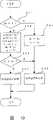
图3是示出控制程序中的制动器释放处理的流程图。FIG. 3 is a flowchart showing brake release processing in the control program.
图4是示出实施形态1的制动器释放处理的子程序流程图。Fig. 4 is a subroutine flowchart showing brake release processing in the first embodiment.
图5是实施形态1的动作说明图。Fig. 5 is an explanatory diagram of the operation of the first embodiment.
图6是示出实施形态2的制动器释放处理的子程序流程图。Fig. 6 is a subroutine flowchart showing brake release processing according to the second embodiment.
图7是实施形态2的动作说明图。Fig. 7 is an explanatory diagram of the operation of the second embodiment.
图8是示出实施形态3的制动器释放处理的子程序流程图。Fig. 8 is a flowchart of a subroutine showing brake release processing according to the third embodiment.
图9是示出实施形态4的制动器释放处理的子程序流程图。Fig. 9 is a subroutine flow chart showing brake release processing according to the fourth embodiment.
图10是示出实施形态5的制动器释放处理的子程序流程图。Fig. 10 is a subroutine flowchart showing brake release processing according to the fifth embodiment.
图11是实施形态5的机械手中到机械手臂前端部或负荷的距离L的说明图。Fig. 11 is an explanatory diagram of the distance L from the manipulator according to the fifth embodiment to the tip of the manipulator arm or to the load.
图12是实施形态5的机械手中到机械手臂前端部或负荷的距离L的说明图。Fig. 12 is an explanatory diagram of the distance L from the manipulator according to the fifth embodiment to the tip of the manipulator arm or to the load.
图13是实施形态6所涉及制动器释放用控制程序的流程图。Fig. 13 is a flowchart of a brake release control program according to the sixth embodiment.
图14是说明多关节机械手的关节部状态的外形图。Fig. 14 is an outline view illustrating the state of the joints of the articulated manipulator.
图15是实施形态6中存储部22所存储制动时间和释放时间的表。Fig. 15 is a table showing the braking time and release time stored in the storage unit 22 in the sixth embodiment.
图16是已有的进行制动器释放的生产用机械手控制装置的框图。Fig. 16 is a block diagram of a conventional production robot control device for brake release.
图17是示出已有制动器释放处理的程序的流程图。FIG. 17 is a flowchart showing a routine of an existing brake release process.
图18是示出已有制动器动作的状态图。Fig. 18 is a state diagram showing the operation of an existing brake.
实施发明的最佳形态The best form for carrying out the invention
实施形态1
图1是示出一般机械手的组成的图,图2是作为本发明实施形态1的机械手的框图。图3是示出控制程序中的制动器释放处理的流程图,图4是示出进行制动器制动和释放处理的子程序的流程图。图5是示出制动器释放开关的状态与制动器信号和机械手臂移动速度的关系的动作说明图。Fig. 1 is a diagram showing the configuration of a general manipulator, and Fig. 2 is a block diagram of a manipulator according to
首先,说明其组成。1是机械手主体,2是进行机械手的各种控制的控制装置,3是进行机械手的操作用的手动操作装置。First, its composition will be described. 1 is a main body of the manipulator, 2 is a control device for performing various controls of the manipulator, and 3 is a manual operation device for manipulating the manipulator.
11是驱动机械手的机械手臂和支柱的电机,12是设置在电机11的轴上,用于检测机械手臂的姿势位置用的位置检测器。13是设置在电机11的轴上,用于在切断机械手电源时防止机械手臂的重力造成的移动的制动器。以上说明的电机11、位置检测器12、制动器13与已有例中的相同。11 is a motor that drives the mechanical arm and the pillar of the manipulator, and 12 is a position detector installed on the shaft of the motor 11 for detecting the posture position of the mechanical arm. 13 is arranged on the shaft of motor 11, is used to prevent the brake that the gravity of mechanical arm causes when cutting off the manipulator power supply. The motor 11, the position detector 12, and the brake 13 explained above are the same as those in the conventional example.
21是中央处理装置,用于分析并处理机械手的动作程序,还用于进行机械手主体1的机械手臂等的姿势控制和以制动器释放控制处理为首的各种处理。中央处理装置21结构上做成:根据存储装置22内的控制程序,以1秒钟约几十次,周期性地每间隔几十毫秒重复进行称为控制程序的一系列位置控制和输入输出处理。构成控制程序执行中,中央处理装置21检测到释放制动器13用的释放操作开关的“导通”时,使存储装置22内的制动器标记Fb的数据为“1”,而且使上次位置数据Xp为“0”。另一方面,构成没有制动器释放指令时,使制动器标记Fb的数据为“0”。然后,在制动器标记Fb为“1”时,构成启动图3所示的制动器释放处理的子程序处理。21 is a central processing unit for analyzing and processing the operation program of the manipulator, and also for performing various processes such as posture control of the manipulator arm of the
22是存储装置,存储动作程序、机械手控制所涉及的各种参数、进行控制装置2内的处理的控制程序及其子程序,以及进行本发明制动器释放处理用的参数。作为进行制动器释放处理用的参数,可分配表明机械手臂等的当前位置和时间的当前位置数据Xc和当前时间数据Tc、表明进行上次处理时的位置和时间的上次位置数据Xp和上次时间数据Tp以及机械手臂等的容许移动速度数据Vs和实际移动速度数据Va。22 is a storage device that stores operating programs, various parameters related to manipulator control, a control program for performing processing in the
23是根据来自中央处理装置21的移动指令产生对机械手的位置控制信号的伺服控制部,24是根据来自伺服控制部23的控制信号对电机11进行驱动的伺服放大部。25是产生制动器的释放控制信号的制动器控制部,26是根据来自制动器控制部25的控制信号,给制动器13提供驱动能量的制动器驱动部。23 is a servo control unit that generates a position control signal to the manipulator based on a movement command from the central processing unit 21 , and 24 is a servo amplifier that drives the motor 11 based on a control signal from the servo control unit 23 . 25 is a brake control unit that generates a brake release control signal, and 26 is a brake drive unit that supplies drive energy to the brake 13 based on a control signal from the brake control unit 25 .
图2中,为了使说明简便,记载电机11、位置检测器12、制动器13、伺服放大部24和制动器驱动部26各一组,但实际上当然设置与机械手主体1所具有驱动部数量相应的多组装置。In Fig. 2, in order to simplify the description, it is described that the motor 11, the position detector 12, the brake 13, the servo amplifier 24, and the brake driver 26 are each in one group, but in fact, of course, the number of drivers corresponding to the number of the manipulator
3是手动操作装置,设置输入动作程序和各种参数、指示本发明制动器释放处理用的按键开关类和进行当前位置显示的显示装置。这里虽然未在图中示出,但有时可在控制装置2中一起设置手动操作装置3的输入和显示功能。3 is a manual operation device, which is provided with a key switch for inputting an action program and various parameters, indicating that the brake release process of the present invention is used, and a display device for displaying the current position. Although not shown here, the input and display functions of the manual operation device 3 may be provided together in the
下面,用图3至图5说明其动作。Next, its operation will be described with reference to FIGS. 3 to 5 .
操作者在指示制动器释放时,操作手动操作3的按键开关,在存储装置22预先存储机械手臂的容许移动速度数据Vs。When the operator instructs to release the brake, he operates the key switch of the manual operation 3, and the allowable moving speed data Vs of the robot arm is stored in the storage device 22 in advance.
首先,在图3的控制程序步骤S31,中央处理装置21检测到释放操作开关为“导通”时,进至步骤S32的处理。步骤32中,停止从伺服控制部23对伺服放大部24的输出信号,禁止对电机11输出。但是,位置检测器23进行位置检测动作,将机械手臂的位置作为当前位置数据Xc等,经伺服控制部23存储到存储部22。First, in step S31 of the control program in FIG. 3 , when the central processing unit 21 detects that the release operation switch is "ON", the process proceeds to step S32. In step 32 , the output signal from the servo control unit 23 to the servo amplifying unit 24 is stopped, and the output to the motor 11 is prohibited. However, the position detector 23 performs a position detection operation, and stores the position of the robot arm in the storage unit 22 via the servo control unit 23 as current position data Xc and the like.
接着,进至步骤S33,但其前释放操作开关为“阻断”状态时,在步骤S36将制动标记Fb设定为“0”,因而仅首次进至步骤S34的处理。步骤S34中,中央处理装置21使制动标记Fb的数据为“1”,并且使上次位置数据Xp为“0”。接着,进至步骤S35,调用图4的制动器释放用的子程序。这样,在释放操作开关为“导通”的期间,总是调用图4的子程序,进行制动器释放处理。Next, the process proceeds to step S33, but when the preceding release operation switch is in the "blocked" state, the brake flag Fb is set to "0" in step S36, and thus proceeds only to the processing of step S34 for the first time. In step S34, the central processing unit 21 sets the data of the brake flag Fb to "1", and sets the previous position data Xp to "0". Next, the process proceeds to step S35, and the subroutine for brake release in FIG. 4 is called. In this way, while the release operation switch is ON, the subroutine in FIG. 4 is always called to perform brake release processing.
步骤S31中,中央处理装置21检测到释放操作开关的状态为“阻断”时,进至步骤S36,使制动标记Fb为“0”,传送从伺服控制部23对伺服放大部24的输出信号,使制动器11释放,通常的伺服系统为控制状态后,退出图3的制动器释放处理程序。In step S31, when the central processing unit 21 detects that the state of the release operation switch is "blocked", it proceeds to step S36, sets the brake flag Fb to "0", and transmits the output from the servo control part 23 to the servo amplifying part 24. signal, the brake 11 is released, and after the common servo system is in the control state, exit the brake release processing program of FIG. 3 .
下面,说明调用图4所示制动器释放子程序时的处理。Next, the processing when the brake release subroutine shown in FIG. 4 is called will be described.
步骤S41中,首先校验上次位置数据Xp是否为“0”,为“0”时,换言之,在释放操作开关从“阻断”切换到“导通”的初始处理中,进至步骤S44,将上次位置数据Xp改写为当前位置数据xc,而且将上次时间数据Tp改写为当前时间数据Tc。此后,进至步骤S46,进行制动器释放处理。制动器释放处理的指令从中央处理装置21通过制动器控制部25送到制动器驱动部26,最后从制动器驱动部26进行供给释放制动器13用的驱动能量。步骤S46的制动器释放处理结束时,暂时退出子程序。In step S41, it is first checked whether the last position data Xp is "0", and when it is "0", in other words, in the initial process of releasing the operation switch from "blocking" to "conducting", proceed to step S44 , the previous position data Xp is rewritten into the current position data xc, and the previous time data Tp is rewritten into the current time data Tc. Thereafter, the process proceeds to step S46 to perform brake release processing. A command for the brake release process is sent from the central processing unit 21 to the brake drive unit 26 through the brake control unit 25 , and finally the brake drive unit 26 supplies drive energy for releasing the brake 13 . When the brake release processing in step S46 ends, the subroutine is temporarily exited.
说明从控制程序中处理下一制动器释放处理的子程序的情况。步骤S31中,释放操作开关仍继续为“导通”,则进至步骤S32,进行伺服系统的控制停止处理。下一步骤S33中,由于在上次执行控制程序制动器释放处理的步骤S34将制动器标记Fb设定为“1”,第2次及其后进至步骤S35,调用图4的制动器释放处理子程序。The case where the subroutine for the next brake release processing is processed from the control program will be described. In step S31, if the operation switch is released and remains "on", the process proceeds to step S32, and the control stop processing of the servo system is performed. In the next step S33, since the brake flag Fb was set to "1" in the step S34 of the brake release process of the previous execution of the control program, the second and subsequent steps proceed to step S35 to call the brake release process subroutine of FIG. 4 .
第2次及其后的子程序调用的步骤S41中,由于上次位置数据Xp代入上次处理时的当前位置数据Xc,所以当前位置数据Xp不为“0”,进至步骤S42。步骤S42中,从下式求上次处理的时刻至当前处理的时刻的移动量ΔX以及经过时间ΔT和实际移动速度数据Va。In step S41 of the second and subsequent subroutine calls, the current position data Xp is not "0" because the previous position data Xp is substituted into the current position data Xc in the previous processing, and the process proceeds to step S42. In step S42, the movement amount ΔX, the elapsed time ΔT, and the actual movement speed data Va from the time of the previous processing to the time of the current processing are obtained from the following formula.
ΔX=Xc-XpΔX=Xc-Xp
ΔT=Tc-TpΔT=Tc-Tp
Va=ΔX/ΔTVa=ΔX/ΔT
上述计算结束后,为了计算调用下次子程序时的移动量和速度,代入当前数据如下。After the above calculation is completed, in order to calculate the movement amount and speed when the subroutine is called next time, substitute the current data as follows.
Xp=XcXp=Xc
Tp=TcTp = Tc
接着,进至步骤S43,在实际移动速度数据Va大于容许移动速度数据Vs时,进至步骤S45,进行控制,使制动器制动;反之,实际移动速度数据Va小于容许移动速度数据Vs时,进至步骤S46,进行控制,使制动器13释放。Then, proceed to step S43, and when the actual moving speed data Va is greater than the allowable moving speed data Vs, proceed to step S45 to control and make the brake brake; otherwise, when the actual moving speed data Va is less than the allowable moving speed data Vs, proceed to step S45. Going to step S46, control is performed so that the brake 13 is released.
如图5的动作说明所示那样,进行以上说明的处理。首先,释放操作开关为“导通”时,利用机械手臂的本身重量使移动开始,在到达移动速度数据Vs前的期间,使制动器13释放。As shown in the operation description of FIG. 5 , the processing described above is performed. First, when the release operation switch is turned ON, the movement is started using the own weight of the robot arm, and the brake 13 is released until the moving speed data Vs is reached.
图5中,以直线近似表示机械手臂的移动速度,但制flc kkd 13释放时的机械手臂移动速度增加的比例因机械手臂的姿势而变化,而且制动器13制动,使移动速度减少的比例取决于制动器13的制动力和机械手臂等的惯性。In Fig. 5, the moving speed of the mechanical arm is approximated by a straight line, but the ratio of the increase in the moving speed of the mechanical arm when the brake flc kkd 13 is released varies with the posture of the mechanical arm, and the ratio of the reduction in the moving speed depends on the braking of the brake 13 Due to the braking force of the brake 13 and the inertia of the robot arm, etc.
达到容许移动速度数据Vs后,在该数据Vs的附近重复进行制动器13的制动和释放处理。释放操作开关为“阻断”时,立即返回伺服系统的控制状态,进行伺服位置控制,使制动器11释放,机械手臂按当前位置数据Xc停止。When the allowable movement speed data Vs is reached, the brake 13 braking and releasing process are repeated around the data Vs. When the release operation switch is "blocked", return to the control state of the servo system immediately, perform servo position control, release the brake 11, and stop the mechanical arm according to the current position data Xc.
如以上说明那样,进行制动器释放处理时,将机械手臂的移动速度限制为容许移动速度,机械手臂不会高速移动,因而能得到安全性高的机械手。As described above, when the brake release process is performed, the moving speed of the robot arm is limited to the allowable moving speed, so that the robot arm does not move at high speed, and thus a highly safe robot arm can be obtained.
实施形态2
实施形态2设计成将实际移动速度与上限容许移动速度和下限容许移动速度比较,超过上限值时进行制动器制动处理,低于下限值时进行制动器释放处理,在上限值与下限值之间时进行上次的处理,其组成与实施形态1相同。
实施形态2的控制程序与实施形态1中图3的流程图相同,其子程序流程图如图6所示,与实施形态1相比,一部分处理不同。与实施形态1中图4相同的处理,其步骤采用相同的步骤编号。图7是示出实施形态2中制动器释放开关的状态与制动器信号和机械手臂移动速度的关系的动作说明图。The control program of
下面,用流程图说明与实施形态1不同的部分。设制动器释放处理启动时,操作者预先从手动操作装置3将上限容许移动速度数据VSH和下限容许移动速度数据VSL输入到存储部22。Next, parts different from
在步骤S42求出实际移动速度数据Va后,进至步骤S51,将实际移动速度数据Va与下限容许移动速度数据VSL比较,实际移动速度数据Va小时,进至步骤S46,进行制动器释放处理。实际移动速度数据Va大时,进至步骤S52。步骤S52中,将实际移动性速度数据Va与上限容许移动速度数据VSH比较,实际移动速度数据Va大时,进至步骤S45,进行制动器制动处理。实际移动速度数据Va小时,退出该子程序,因而继续进行上次处理的步骤S45的制动器制动处理或步骤S46的制动器释放处理。After obtaining the actual moving speed data Va in step S42, proceed to step S51, compare the actual moving speed data Va with the lower limit allowable moving speed data VSL , if the actual moving speed data Va is small, proceed to step S46, and perform brake release processing. When the actual moving speed data Va is large, the process proceeds to step S52. In step S52, the actual mobility speed data Va is compared with the upper limit permissible movement speed dataVSH , and if the actual movement speed data Va is larger, the process proceeds to step S45, and the brake application process is performed. When the actual moving speed data Va is small, this subroutine is exited, and the brake application process of step S45 or the brake release process of step S46 in the previous process is continued.
实施形态2与实施形态1相比,如图7所示,制动器制动和制动器释放的处理间隔变大,能减少制动器13的制动和释放的跳跃频度。In
实施形态3Implementation form 3
实施形态3设计成在伺服系统为控制停止状态,进行机械手臂的制动器释放时,利用位置检测器检测出机械手臂的移动位置,求出在制动器释放程序执行周期中进行移动的机械手臂移动量,将该机械手臂移动量与设定的移动量比较,以控制制动器的制动和释放;其组成与实施形态1相同。Embodiment 3 is designed such that when the servo system is in a controlled stop state and the brake of the robot arm is released, the position detector is used to detect the moving position of the robot arm, and the movement amount of the robot arm that moves during the execution period of the brake release program is obtained, The moving amount of the robot arm is compared with the set moving amount to control braking and releasing of the brake; its composition is the same as that of
实施形态3的控制程序与实施形态1中图3的流程图相同,其子程序的流程图如图8所示,与实施形态1相比,一部分处理不同。与实施形态1的图4相同的处理,其步骤采用相同的步骤编号。The control program of the third embodiment is the same as the flowchart of FIG. 3 in the first embodiment, and the flowchart of its subroutine is shown in FIG. 8. Compared with the first embodiment, a part of processing is different. For the same processing as in Fig. 4 of the first embodiment, the same step numbers are used for the steps.
下面,说明制动器释放用子程序中不同的部分。Next, the different parts of the subroutine for brake release will be described.
释放操作开关从“阻断”切换到“导通”的初始子程序调用中,上次位置数据Xp设定为“0”,因而从步骤S41进至步骤S55。步骤S55中,上次位置数据Xp代入当前位置数据Xc,并进至步骤S46,进行制动器释放处理后,退出子程序。In the initial subroutine call in which the operation switch is released and switched from "off" to "on", the previous position data Xp is set to "0", so the process proceeds from step S41 to step S55. In step S55, the previous position data Xp is substituted into the current position data Xc, and the process proceeds to step S46, where the brake release process is performed and the subroutine is exited.
第2次及其后的子程序调用中,作为上次位置数据,在步骤S55代入上次处理时的当前位置数据Xc,因而步骤S41的判断进至步骤S53。步骤S53中,从当前位置数据Vs与上次位置数据Xp的差求出实际移动量ΔX。然后,在步骤S54将实际移动量ΔX与设定移动量Xs相比,实际移动量ΔX大时,进行步骤S45的制动器制动处理,实际移动量ΔX小时,进行步骤S46的制动器释放处理。In the second and subsequent subroutine calls, the current position data Xc at the time of the previous processing is substituted in step S55 as the previous position data, so the judgment in step S41 proceeds to step S53. In step S53, the actual movement amount ΔX is obtained from the difference between the current position data Vs and the previous position data Xp. Then, in step S54, the actual movement amount ΔX is compared with the set movement amount Xs. If the actual movement amount ΔX is large, the brake application process is performed in step S45, and if the actual movement amount ΔX is small, the brake release process is performed in step S46.
如以上说明那样,释放操作开关“导通“时,机械手臂利用本身重量开始移动,在每次控制程序执行处理的实际移动量ΔX达到设定移动量Xs前的期间,使制动器13释放。此后,以设定移动量Xs为基准,进行制动器13的制动和释放。释放操作开关“阻断”时,立即返回伺服系统的控制状态,进行伺服位置控制,使制动器11释放,机械手臂按当前位置数据停止。As described above, when the operation switch is released to "ON", the robot arm starts to move by its own weight, and the brake 13 is released until the actual movement amount ΔX of each control program execution process reaches the set movement amount Xs. Thereafter, braking and releasing of the brake 13 are performed based on the set movement amount Xs. When the operating switch "blocking" is released, the control state of the servo system is returned immediately, the servo position control is performed, the brake 11 is released, and the mechanical arm stops according to the current position data.
实施形态3中,以1秒种约几十次,周期性地每间隔几十毫秒实施控制程序的执行,利用经过时间ΔT为大致固定的时间间隔,因而能省略中央处理装置21计算经过时间ΔT的处理。In Embodiment 3, the execution of the control program is performed periodically at intervals of several tens of milliseconds about tens of times per second, and the elapsed time ΔT is used as a substantially constant time interval, so the calculation of the elapsed time ΔT by the central processing unit 21 can be omitted. processing.
又,不仅将设定移动量Xs作为直接参数设定,而且输入容许移动速度数据Vs,因而结构上可做成利用中央处理装置21求出设定移动量Xs,存入存储部22。而且,结构上还可做成:用作为从位置检测器12送到伺服控制部23的位置信号的脉冲数代替设定移动量Xs。Moreover, not only setting the set moving amount Xs as a direct parameter, but also inputting the allowable moving speed data Vs, it is structurally possible to obtain the set moving amount Xs by the central processing unit 21 and store it in the storage unit 22 . In addition, it is also possible to configure the number of pulses as a position signal sent from the position detector 12 to the servo control unit 23 instead of the set movement amount Xs.
实施形态4
实施形态4用于如多关节机械手那样,从关节看,机械手主体1的机械手臂的姿势和负荷等的合成重心处于大致垂直位置,并且关节旋转的转矩接近“0”时,或者正交型机械手的移动轴大致水平配置,并且机械手臂不移动时,避免即使释放制动器13,操作者不加力,机械手臂就不开始移动的现象。其中设计成电机辅助旋转开关“导通”时,使电机11进行旋转动作,直到机械手臂的实际移动速度数据Va变成容许移动速度数据。
实施形态4的控制程序与实施形态1中图3的流程图相同,其子程序的流程图如图9所示,与实施形态1相比,一部分处理不同。与实施形态1的图4相同的处理,其步骤采用相同的步骤编号。The control program of
下面,说明制动器释放用子程序中不同的部分。Next, the different parts of the subroutine for brake release will be described.
第2次及其后的子程序调用中,将“0”以外的值代入上次位置数据Xp,因而步骤S41的判断进至步骤S42。步骤S42中,从下式求出上次处理时至当前处理时的移动量ΔX、经过时间ΔT和实际移动速度Va。In the second and subsequent subroutine calls, a value other than "0" is substituted into the previous position data Xp, so the judgment in step S41 proceeds to step S42. In step S42, the movement amount ΔX, the elapsed time ΔT, and the actual movement speed Va from the previous processing to the current processing are obtained from the following equations.
ΔX=Xc-XpΔX=Xc-Xp
ΔT=Tc-TpΔT=Tc-Tp
Va=ΔX/ΔTVa=ΔX/ΔT
上述计算结束后,为了计算调用下次子程序时的移动量和速度,代入当前数据如下。After the above calculation is completed, in order to calculate the movement amount and speed when the subroutine is called next time, substitute the current data as follows.
Xp=XcXp=Xc
Tp=TcTp = Tc
接着,进至步骤S43,在实际移动速度数据Va大于容许移动速度数据Vs时,进至步骤S45,进行制动器制动处理后,退出子程序。实际移动速度数据Va小于容许移动速度数据Vs时,进至步骤S56。如果电机辅助旋转开关“导通”,进至步骤S57,进行制动器释放处理,给电机11施加机械手臂移动程度的一定转矩后,退出子程序。步骤S56中,电机辅助旋转开关“阻断”,则进至步骤S46,执行制动器释放处理后,退出子程序。Next, it proceeds to step S43, and when the actual moving speed data Va is greater than the allowable moving speed data Vs, it proceeds to step S45, performs brake braking processing, and then exits the subroutine. When the actual moving speed data Va is smaller than the allowable moving speed data Vs, the process proceeds to step S56. If the auxiliary rotary switch of the motor is "on", proceed to step S57 to perform brake release processing, apply a certain torque to the motor 11 to the degree of movement of the mechanical arm, and exit the subroutine. In step S56, if the motor auxiliary rotary switch is "blocked", then go to step S46, execute the brake release process, and exit the subroutine.
如以上说明那样,电机辅助旋转开关“导通”时,机械手臂利用本身重量开始自行,在其达到容许移动速度Vs前的期间,进行借助电机11的机械手臂辅助移动动作。即使电机辅助旋转开关“阻断”且机械手臂停止状态继续时,操作者加力,也能任意移动机械手臂。As described above, when the motor-assisted rotary switch is turned on, the robot arm starts to move by itself with its own weight, and performs the robot-arm-assisted movement by the motor 11 until it reaches the allowable moving speed Vs. Even when the motor-assisted rotary switch is "blocked" and the stop state of the robot arm continues, the operator can apply force to move the robot arm freely.
而且,结构上做成给电机11施加的辅助移动用转矩按使机械手臂开始移动程度的一定转矩加以控制,则即使因操作差错而操作者使电机11旋转到行程的末端,机械手主体1也没有机械上的损坏。And structurally, the auxiliary movement torque applied to the motor 11 is controlled by a certain torque to the extent that the mechanical arm starts to move, even if the operator rotates the motor 11 to the end of the stroke due to an operation error, the manipulator
实施形态5
实施形态5与实施形态1相同,也利用位置检测器检测出机械手臂的移动位置,并根据移动位置和经过时间的位置变化量计算机械手臂的实际运动速度。但是,实施形态5的不同点是:根据实际移动速度和与机械手臂前端部工作点的距离,求出机械手臂前端部工作点的移动速度,将其与容许移动速度比较,在机械手臂前端部工作点的移动速度大时,进行制动器制动处理,小则进行制动器释放处理。
因此,实施形态5的控制程序与实施形态1中图3的流程图相同,其子程序流程图如图10所示,与实施形态1相比,一部分处理不同。Therefore, the control program of the fifth embodiment is the same as the flow chart of FIG. 3 in the first embodiment, and its subroutine flow chart is shown in FIG. 10. Compared with the first embodiment, a part of processing is different.
图11和图12是说明图,说明机械手主体1中从进行制动器释放的关节部X1到机械手臂前端部工作点(用A点表示)的距离L。X1、X2、X3分别表示各关节部的坐标数据,L1、L2、L3分别表示第1机械手臂14、第2机械手臂15、手腕轴16的关节间距离或关节与工作点之间的距离。θ1表示第1机械手臂14与水平面的夹角,θ2、θ3表示各关节部的机械手臂间夹角。17为负荷,18为机械手支柱,W为负荷的重量。11 and 12 are explanatory diagrams illustrating the distance L from the joint X1 where the brake is released in the manipulator main body1 to the working point (indicated by point A) at the front end of the manipulator. X1 , X2 , and X3 respectively represent the coordinate data of each joint, and L1 , L2 , and L3 represent the distance between joints or the distance between the joints of the
下面,用流程图说明与实施形态1不同的处理。设制动器释放处理启动时,操作者从手动操作3预先将容许移动速度数据Vs、到前端部或负荷中心的距离L输入到存储部22。Next, processing different from
首先,在图10所示流程图的第2次子程序调用的步骤S41中,与实施形态1相同,上次位置数据Xp代入上次处理时的当前位置数据,因而上次位置数据Xp不是“0”,进至步骤S58。步骤S58中,从下式求出上次处理时到当前处理时的移动量ΔX、经过时间ΔT、实际移动速度数据Va和移动速度数据V。First, in step S41 of the second subroutine call in the flow chart shown in FIG. 10, as in
ΔX=Xc-XpΔX=Xc-Xp
ΔT=Tc-TpΔT=Tc-Tp
Va=ΔX/ΔTVa=ΔX/ΔT
V=Va×LV=Va×L
上述计算结束后,为了计算调用下次子程序时的移动量和速度,代入当前数据如下。After the above calculation is completed, in order to calculate the movement amount and speed when the subroutine is called next time, substitute the current data as follows.
Xp=XcXp=Xc
Tp=TcTp = Tc
接着,进至步骤S59,进行控制,以便在移动速度数据大于容许移动速度数据Vs时,进至步骤S45,使制动器制动;反之,移动速度数据V小于容许移动速度数据Vs时,进至步骤S46,使制动器13释放。Then, proceed to step S59 and control so that when the moving speed data is greater than the allowable moving speed data Vs, proceed to step S45 to brake the brake; otherwise, when the moving speed data V is less than the allowable moving speed data Vs, proceed to step S46, the brake 13 is released.
以上的说明阐述了操作者输入距离L的情况。然而,结构上做成利用根据并节间的距离L1、L2、L3和各关节间的夹角θ1、θ2、θ3进行计算,求出距离L,则可省略操作者输入距离L的操作。The above description has explained the case where the operator inputs the distance L. FIG. However, if the distance L is calculated by calculating the distance L1 , L2 , L3 between joints and the angles θ1 , θ2 , θ3 between joints, the operator input can be omitted The operation of distance L.
实施形态6
实施形态6使机械手主体1的机械手臂姿势和负荷状态与制动器释放处理的制动时间和释放时间相互关联关存储到存储部22,按照存储的制动时间和释放时间控制制动器13。
图13表示实施形态6的制动器释放用控制程序的流程图,图14示出说明多关节机械手的关节部状态的外形图,图15示出存储部22存储的制动时间和释放时间的表。13 is a flow chart of a brake release control program according to
图14示出说明实施形态6中各种参数用的机械手主体的外形图,14为第1机械手臂,15为第2机械手臂,16为手腕轴。17是负荷,在机械手中相当于搬运物。18是支柱,支持第1机械手臂14进行旋转。Fig. 14 shows an outline view of the main body of the manipulator for explaining various parameters in
X1表是关节坐标数据,该数据在用角度θ1表示支柱18与第1机械手臂的关节部的状态时,受控制装置2管理。作为具体的坐标设定,可取为θ1=X1,但用θ1=X1+α的关系式表示。α一般将行程末端规定为“0”的情况居多。同样,X2表示用角度θ2表示第1机械手臂14与第2机械手臂15的关节部状态时的坐标数据,X3表示用角度θ3示出第2机械手臂15与手腕轴16的关节部状态时的坐标数据。The X1 table is joint coordinate data, and this data is managed by the
图15的表将表示机械手臂姿势的第1关节坐标数据X1分为A1至F1的5个区,将第2关节旋转位置X2分为A2~E2的4个区,将第3关节旋转位置X3分为A3~C3的2个区,还将负荷17的重量W分为0、2、4kg的3个区,并且使各区与最佳制动器的释放时间TBRn和释放时间TBLn的数据关联。这些表数据相互关联地存储到存储部22,构成中央处理装置21可从第1关节至第3关节的位置数据X1、X2、X3和重量W的输入数据方便地检索并读出制动器的释放时间TBRn和制动时间TBLn。The table in Fig. 15 divides the coordinate dataX1 of the first joint representing the posture of the robot arm into five areas fromA1 toF1 , and divides the rotational positionX2 of the second joint into four areas fromA2 toE2 . The rotation position X3 of Joint #3 is divided into 2 zones of A3 ~ C3 , and the weight W of the
下面,用图13的流程图说明动作。Next, the operation will be described using the flowchart in FIG. 13 .
调用控制程序中的制动器释放程序时,在步骤S61判断释放操作开关的状态,如果该开关“阻断”,进至步骤S69,在设定的制动器制动时间TBL和设定的制动器释放时间TBR中设置“-1”后,退出制动器释放处理。步骤S61中,释放操作开关为“导通”时,进至步骤S62,进行伺服输出停止处理,停止从伺服放大部24对电机11的输出。接着,进至步骤S63,判断设定的制动器制动时间TBL和设定的制动器释放时间TBR是否均为负值。释放操作开关从“阻断”切换到“导通”后,该2个时间均为负值,因而进至步骤S64,根据各关节的当前位置X1、X2、X3和输入的负荷信息W,读出最近条件的设定制动器制动时间TBRn和设定制动器释放时间TBRn,设定为When the brake release program in the control program is called, the state of the release operation switch is judged in step S61, if the switch is "blocked", go to step S69, and the set brake braking time TBL and the set brake release time When "-1" is set in TBR , the brake release processing is exited. In step S61, when the release operation switch is turned ON, the process proceeds to step S62, and servo output stop processing is performed to stop the output from the servo amplifier 24 to the motor 11 . Next, proceed to step S63, and judge whether the set brake application time TBL and the set brake release time TBR are both negative values. After the operating switch is released and switched from "blocking" to "conducting", the two times are negative, so go to step S64, according to the current positions X1 , X2 , X3 of each joint and the input load information W, read the set brake braking time TBRn and the set brake release time TBRn of the latest conditions, set as
TBL=TBLnTBL =TBLn
TBR=TBRn。TBR =TBRn .
接着,进至步骤S68,进行制动器释放处理,从设定的制动器释放时间TBR减去到下次处理需要的时间ΔT后,退出制动器释放处理程序。重复进行步骤S68的制动器释放处理,直到经历设定的制动器释放时间TBR为止。步骤S65中,设定的制动器释放时间为负后,即制动器释放处理结束后,进至步骤S66,重复进行步骤S67的制动器制动处理,直到经历制动器制动时间TBL为止。Next, the process proceeds to step S68 to perform brake release processing, subtract the time ΔT required for the next processing from the set brake release time TBR , and then exit the brake release processing routine. The brake release process of step S68 is repeated until the set brake release time TBR elapses. In step S65, after the set brake release time becomes negative, that is, after the brake release process is completed, proceed to step S66, and repeat the brake application process of step S67 until the brake application time TBL elapses.
步骤S68的制动器释放处理和步骤S67的制动器制动处理的一个周期结束时,再次进至步骤S64,根据各关节的当前位置和输入的负荷消息,读出新的设定制动器制动时间TBL和设定制动器释放时间TBR,重复进行制动器释放处理。When one cycle of the brake release processing in step S68 and the brake application processing in step S67 ends, go to step S64 again, and read out the new set brake braking time TBL according to the current position of each joint and the input load information And setting the brake release time TBR , the brake release processing is repeated.
如以上说明那样,根据机械手主体1的各关节的当前位置坐标值和输入负荷调用存储部22存储的最佳设定制动器制动时间TBLn和最佳设定制动器释放时间TBRn,进行制动器释放处理,因而不像实施形态1和实施形态3那样,进行根据当前位置数据Xc、上次位置数据Xp、当前时间数据Tc、上次时间数据Tp等求实际旋转速度数据Va等计算也可完事,能简化处理。As described above, the brake is released based on the current position coordinate values of each joint of the
每当进行制动器释放、制动控制时,以上说明的各实施形态中,可适当改换按容许移动速度比较移动速度,或者将控制程序执行周期内的移动量与容许移动量比较,或者容许移动速度或容许移动量设置上限值和下限值进行比较的技术,或组合两种以上技术进行使用。Whenever brake release and brake control are performed, in each of the embodiments described above, the comparison of the movement speed by the allowable movement speed can be appropriately changed, or the movement amount in the control program execution cycle can be compared with the allowable movement amount, or the allowable movement speed can be compared. Or a technique that allows comparison of the upper limit value and lower limit value of the allowable movement amount, or a combination of two or more techniques.
生产上的可用性production availability
如以上那样,本发明所涉及的机械手适用于进行制动器释放,使机械手臂移动到行程范围外或从行程范围外移动到范围内的情况。As described above, the robot arm according to the present invention is suitable for releasing the brake and moving the robot arm out of the stroke range or from outside the stroke range to within the range.
Claims (10)
Applications Claiming Priority (1)
| Application Number | Priority Date | Filing Date | Title |
|---|---|---|---|
| PCT/JP2002/003679WO2003086718A1 (en) | 2002-04-12 | 2002-04-12 | Robot |
Publications (2)
| Publication Number | Publication Date |
|---|---|
| CN1481298A CN1481298A (en) | 2004-03-10 |
| CN1305648Ctrue CN1305648C (en) | 2007-03-21 |
Family
ID=11738143
Family Applications (1)
| Application Number | Title | Priority Date | Filing Date |
|---|---|---|---|
| CNB028022599AExpired - Fee RelatedCN1305648C (en) | 2002-04-12 | 2002-04-12 | manipulator |
Country Status (8)
| Country | Link |
|---|---|
| US (1) | US6917856B2 (en) |
| JP (1) | JP4277683B2 (en) |
| KR (1) | KR100483660B1 (en) |
| CN (1) | CN1305648C (en) |
| DE (1) | DE10296748T5 (en) |
| GB (1) | GB2387672B (en) |
| TW (1) | TW542773B (en) |
| WO (1) | WO2003086718A1 (en) |
Cited By (1)
| Publication number | Priority date | Publication date | Assignee | Title |
|---|---|---|---|---|
| CN110216679A (en)* | 2019-06-28 | 2019-09-10 | 北京猎户星空科技有限公司 | A kind of mechanical arm unlocking method and device |
Families Citing this family (45)
| Publication number | Priority date | Publication date | Assignee | Title |
|---|---|---|---|---|
| GB0302094D0 (en)* | 2003-01-29 | 2003-02-26 | Pharmagene Lab Ltd | EP4 receptor antagonists |
| JP4473076B2 (en)* | 2004-08-30 | 2010-06-02 | 株式会社日立産機システム | Control method and apparatus for linear synchronous motor |
| JP4508164B2 (en)* | 2006-06-26 | 2010-07-21 | トヨタ自動車株式会社 | Articulated robot and its control program |
| EP1932629B1 (en)* | 2006-12-11 | 2019-04-24 | ABB Research Ltd. | A method and a control system for monitoring the condition of an industrial robot |
| DE102007023847B4 (en)* | 2007-05-23 | 2011-12-08 | Siemens Ag | shoulder joint |
| DE102007023848B4 (en)* | 2007-05-23 | 2012-08-02 | Siemens Ag | shoulder joint |
| US8588958B2 (en)* | 2007-09-04 | 2013-11-19 | Musashi Engineering, Inc. | Moving program making-out program and device |
| EP2067580A1 (en)* | 2007-12-04 | 2009-06-10 | Metris IPR N.V. | Articulated arm measuring machine endowed with automatic brake |
| EP2224586A1 (en) | 2009-02-26 | 2010-09-01 | Carl Cloos Schweisstechnik GmbH | Method for controlling a motor-operated industry robot and industry robot for carrying out such a method |
| JP5218524B2 (en)* | 2010-03-15 | 2013-06-26 | 株式会社安川電機 | Robot system and robot operation restriction method |
| DE102010027248A1 (en) | 2010-07-15 | 2012-01-19 | Sensodrive Gmbh | Holding device for an instrument |
| JP5154712B2 (en)* | 2010-12-08 | 2013-02-27 | パナソニック株式会社 | ROBOT CONTROL DEVICE AND CONTROL METHOD, ROBOT, AND CONTROL PROGRAM |
| CN102310407B (en)* | 2011-04-22 | 2014-10-15 | 三一重工股份有限公司 | Bionic control method and control system of mechanical arm |
| DE102012021370B3 (en)* | 2012-11-04 | 2014-02-06 | Martin Hoerdum | Full-suspension folding cycle for use manual or electrical drive, as bicycle, tricycle or quadric-cycle, has frame, luggage carrier, handlebars, kickstand and pedals, which are unfolded out and folded up |
| DE102012003479A1 (en) | 2012-02-21 | 2013-08-22 | Kuka Roboter Gmbh | Method and device for carrying out a manipulator process |
| US9114536B2 (en) | 2012-04-13 | 2015-08-25 | Rethink Robotics, Inc. | Electronic emergency-stop braking circuit for robotic arms |
| CN103713526B (en)* | 2012-10-09 | 2016-08-17 | 亚得力科技股份有限公司 | Intelligent motor controller, control method, external circuit and its motor remote controller |
| KR101994487B1 (en)* | 2012-12-18 | 2019-07-01 | 두산공작기계 주식회사 | Method for controlling feed axix brake of machine tool |
| JP5408371B2 (en)* | 2013-01-23 | 2014-02-05 | 株式会社デンソーウェーブ | Robot electromagnetic brake control device |
| CN103240739B (en)* | 2013-05-07 | 2015-04-15 | 武汉科技大学 | Automatic switching control method for decentralization and centralization of mobile manipulators |
| DE102013020697B4 (en)* | 2013-12-04 | 2023-07-06 | Kuka Roboter Gmbh | Method and control means for controlling a robot |
| EP4248901A3 (en)* | 2014-03-17 | 2023-11-29 | Intuitive Surgical Operations, Inc. | System and method for breakaway clutching in an articulated arm |
| FR3019953B1 (en)* | 2014-04-09 | 2016-05-06 | Staubli Sa Ets | METHOD FOR CONTROLLING A MULTI-AXIS AND ROBOT ROBOT FOR IMPLEMENTING SUCH A METHOD |
| CN104016134B (en)* | 2014-06-12 | 2016-06-01 | 泰山医学院 | The vacuum handling equipment of a kind of sintered neodymium-iron-boron powder |
| CN104192573B (en)* | 2014-07-29 | 2016-05-11 | 福建海源自动化机械股份有限公司 | Stacking machine running state monitoring and Braking mode method and apparatus |
| KR102479287B1 (en) | 2014-10-27 | 2022-12-20 | 인튜어티브 서지컬 오퍼레이션즈 인코포레이티드 | System and method for monitoring control points during reactive motion |
| EP3212107B1 (en) | 2014-10-27 | 2025-04-09 | Intuitive Surgical Operations, Inc. | Medical device with active brake release control |
| US10624807B2 (en) | 2014-10-27 | 2020-04-21 | Intuitive Surgical Operations, Inc. | System and method for integrated surgical table icons |
| CN110236853B (en) | 2014-10-27 | 2021-06-04 | 直观外科手术操作公司 | System and method for registration to an operating table |
| KR102545930B1 (en) | 2014-10-27 | 2023-06-22 | 인튜어티브 서지컬 오퍼레이션즈 인코포레이티드 | System and method for integrated surgical table |
| WO2016069663A1 (en) | 2014-10-27 | 2016-05-06 | Intuitive Surgical Operations, Inc. | System and method for integrated surgical table motion |
| EP4082466B1 (en) | 2014-10-27 | 2025-07-30 | Intuitive Surgical Operations, Inc. | System for instrument disturbance compensation |
| JP2016159367A (en)* | 2015-02-26 | 2016-09-05 | ファナック株式会社 | Robot control device for automatically switching operation mode of robot |
| EP3270813A4 (en) | 2015-03-17 | 2018-11-07 | Intuitive Surgical Operations, Inc. | System and method for providing feedback during manual joint positioning |
| JP6603480B2 (en)* | 2015-05-20 | 2019-11-06 | 川崎重工業株式会社 | Electrical equipment mounting apparatus and method |
| TWI674179B (en)* | 2016-01-18 | 2019-10-11 | 廣明光電股份有限公司 | Method for releasing the brake of a robot arm |
| DE102017005604A1 (en)* | 2017-06-12 | 2018-12-13 | Kuka Deutschland Gmbh | Monitoring a robot |
| CN111093912B (en)* | 2017-09-08 | 2023-02-17 | Ntn株式会社 | Working device with parallel linkage mechanism |
| JP7207010B2 (en)* | 2019-02-27 | 2023-01-18 | セイコーエプソン株式会社 | Robot system and its control method |
| JP7285668B2 (en)* | 2019-03-22 | 2023-06-02 | 株式会社ジャノメ | Robot and its brake control program |
| JP2020168676A (en)* | 2019-04-02 | 2020-10-15 | 蛇の目ミシン工業株式会社 | Robot and brake control program of the same |
| US11667035B2 (en)* | 2019-07-01 | 2023-06-06 | Wisconsin Alumni Research Foundation | Path-modifying control system managing robot singularities |
| KR102746515B1 (en)* | 2019-09-19 | 2024-12-23 | 엘지전자 주식회사 | Control server and method for controlling robot using artificial neural network, and the robot implementing the same |
| JP7567534B2 (en)* | 2021-02-10 | 2024-10-16 | セイコーエプソン株式会社 | Robot System |
| CN120677038A (en)* | 2023-07-03 | 2025-09-19 | 深圳华大智造云影医疗科技有限公司 | Robot posture processing method and device, electronic device and storage medium |
Citations (6)
| Publication number | Priority date | Publication date | Assignee | Title |
|---|---|---|---|---|
| JPH10151596A (en)* | 1996-11-20 | 1998-06-09 | Toyoda Mach Works Ltd | Robot control device |
| JPH11179691A (en)* | 1997-12-19 | 1999-07-06 | Mitsubishi Electric Corp | Robot control device |
| US5969973A (en)* | 1994-11-09 | 1999-10-19 | Amada Company, Ltd. | Intelligent system for generating and executing a sheet metal bending plan |
| JP2000047732A (en)* | 1998-07-31 | 2000-02-18 | Yaskawa Electric Corp | Servo control device and servo control method |
| US6166504A (en)* | 1998-12-22 | 2000-12-26 | Denso Corporation | Control apparatus for robot having an arm moving within allowable working area |
| US6356806B1 (en)* | 1998-12-12 | 2002-03-12 | Kuka Roboter Gmbh | Method for handling a voltage drop in the control of a robot and for restarting a robot following a voltage drop |
Family Cites Families (1)
| Publication number | Priority date | Publication date | Assignee | Title |
|---|---|---|---|---|
| JP3409090B2 (en) | 1993-09-30 | 2003-05-19 | 豊田工機株式会社 | Robot start / stop device |
- 2002
- 2002-04-12GBGB0303210Apatent/GB2387672B/ennot_activeExpired - Fee Related
- 2002-04-12CNCNB028022599Apatent/CN1305648C/ennot_activeExpired - Fee Related
- 2002-04-12DEDE10296748Tpatent/DE10296748T5/ennot_activeWithdrawn
- 2002-04-12JPJP2003521675Apatent/JP4277683B2/ennot_activeExpired - Fee Related
- 2002-04-12USUS10/343,913patent/US6917856B2/ennot_activeExpired - Lifetime
- 2002-04-12KRKR10-2003-7002914Apatent/KR100483660B1/ennot_activeExpired - Fee Related
- 2002-04-12WOPCT/JP2002/003679patent/WO2003086718A1/enactiveApplication Filing
- 2002-04-25TWTW091108511Apatent/TW542773B/ennot_activeIP Right Cessation
Patent Citations (6)
| Publication number | Priority date | Publication date | Assignee | Title |
|---|---|---|---|---|
| US5969973A (en)* | 1994-11-09 | 1999-10-19 | Amada Company, Ltd. | Intelligent system for generating and executing a sheet metal bending plan |
| JPH10151596A (en)* | 1996-11-20 | 1998-06-09 | Toyoda Mach Works Ltd | Robot control device |
| JPH11179691A (en)* | 1997-12-19 | 1999-07-06 | Mitsubishi Electric Corp | Robot control device |
| JP2000047732A (en)* | 1998-07-31 | 2000-02-18 | Yaskawa Electric Corp | Servo control device and servo control method |
| US6356806B1 (en)* | 1998-12-12 | 2002-03-12 | Kuka Roboter Gmbh | Method for handling a voltage drop in the control of a robot and for restarting a robot following a voltage drop |
| US6166504A (en)* | 1998-12-22 | 2000-12-26 | Denso Corporation | Control apparatus for robot having an arm moving within allowable working area |
Cited By (2)
| Publication number | Priority date | Publication date | Assignee | Title |
|---|---|---|---|---|
| CN110216679A (en)* | 2019-06-28 | 2019-09-10 | 北京猎户星空科技有限公司 | A kind of mechanical arm unlocking method and device |
| CN110216679B (en)* | 2019-06-28 | 2020-07-10 | 北京猎户星空科技有限公司 | Mechanical arm unlocking method and device |
Also Published As
| Publication number | Publication date |
|---|---|
| WO2003086718A1 (en) | 2003-10-23 |
| JP4277683B2 (en) | 2009-06-10 |
| JPWO2003086718A1 (en) | 2005-08-18 |
| CN1481298A (en) | 2004-03-10 |
| KR100483660B1 (en) | 2005-04-19 |
| GB0303210D0 (en) | 2003-03-19 |
| US20030192758A1 (en) | 2003-10-16 |
| GB2387672B (en) | 2004-11-24 |
| KR20040014393A (en) | 2004-02-14 |
| DE10296748T5 (en) | 2005-06-02 |
| GB2387672A (en) | 2003-10-22 |
| TW542773B (en) | 2003-07-21 |
| US6917856B2 (en) | 2005-07-12 |
Similar Documents
| Publication | Publication Date | Title |
|---|---|---|
| CN1305648C (en) | manipulator | |
| CN1258125C (en) | Method of controlling speed of eletric machine for driving robot | |
| CN1131766C (en) | Robot control equipment | |
| CN1076422C (en) | Interference prevention device for two-piece boom type hydraulic excavator | |
| CN1401098A (en) | Robot controller | |
| CN1319478A (en) | Robot Demonstration device, robot using same and robot operation method | |
| EP2868403B1 (en) | Robot system and method for producing to-be-processed material | |
| CN1160108A (en) | Construction machinery operating range limit control device | |
| JP2016179510A (en) | Robot control device having function of detecting contact with object or person | |
| CN1579717A (en) | Articulated robot | |
| KR20040011488A (en) | Machining control method, machining control device, computer program for executing the method, and information storage medium having the computer program stored therein | |
| KR102526985B1 (en) | robot bending system for factory automation | |
| CN1137805C (en) | Lifting device for component adsorption nozzle | |
| JP6117673B2 (en) | Robot origin setting method and robot | |
| US12168261B2 (en) | Friction stir joining device, method of operating the same and joint structure | |
| CN1182002A (en) | welding torch | |
| JP2002178168A (en) | Friction stir welding equipment | |
| CN1299175C (en) | Digital controller | |
| JP7350394B2 (en) | robot equipment | |
| US12194633B2 (en) | Method for controlling robot, robot system, and storage medium | |
| US12162168B2 (en) | Method for controlling robot, robot system, and storage medium | |
| CN1377756A (en) | Processing device and detecting method for processing result | |
| KR101812026B1 (en) | 6-axis articulated robot | |
| US10723023B2 (en) | Control device and control method for controlling workpiece moving device and robot to operate in cooperation with each other | |
| CN1950769A (en) | A control unit of a machine and associated methods |
Legal Events
| Date | Code | Title | Description |
|---|---|---|---|
| C06 | Publication | ||
| PB01 | Publication | ||
| C10 | Entry into substantive examination | ||
| SE01 | Entry into force of request for substantive examination | ||
| C14 | Grant of patent or utility model | ||
| GR01 | Patent grant | ||
| CF01 | Termination of patent right due to non-payment of annual fee | Granted publication date:20070321 Termination date:20190412 | |
| CF01 | Termination of patent right due to non-payment of annual fee |