CN1305445C - Power generating and monitoring circuit of radio frequency melting therapeutic system - Google Patents
Power generating and monitoring circuit of radio frequency melting therapeutic systemDownload PDFInfo
- Publication number
- CN1305445C CN1305445CCNB2004100530343ACN200410053034ACN1305445CCN 1305445 CCN1305445 CCN 1305445CCN B2004100530343 ACNB2004100530343 ACN B2004100530343ACN 200410053034 ACN200410053034 ACN 200410053034ACN 1305445 CCN1305445 CCN 1305445C
- Authority
- CN
- China
- Prior art keywords
- circuit
- output
- voltage
- power supply
- direct current
- Prior art date
- Legal status (The legal status is an assumption and is not a legal conclusion. Google has not performed a legal analysis and makes no representation as to the accuracy of the status listed.)
- Expired - Fee Related
Links
Images


Landscapes
- Amplifiers (AREA)
- Investigating Or Analyzing Materials By The Use Of Electric Means (AREA)
Abstract
Translated fromChinese
Description
Translated fromChinese技术领域technical field
本发明涉及的是一种用于生物医学工程技术领域的肿瘤消融治疗系统的电路,尤其是是一种射频消融治疗系统的功率发生和监控电路。The invention relates to a circuit for a tumor ablation treatment system in the technical field of biomedical engineering, especially a power generating and monitoring circuit for a radiofrequency ablation treatment system.
背景技术Background technique
基于射频电磁场生物热效应的射频消融,即射频原位灭活已在肿瘤治疗、心胸外科、神经外科、妇科和泌尿外科等等临床中得到了广泛的应用,各类相应的医疗设备,诸如水冷式射频肿瘤消融治疗系统、多弹头肿瘤射频消融仪、房颤射频消融治疗仪等等已大量出现。在射频消融手术过程中,射频消融治疗系统的输出功率合适与否是至关重要的,过低则达不到消融的目的,过高又会使靶组织因温度过高而气化结碳,同样达不到良好的消融效果。靶组织的阻抗,亦即射频消融治疗系统的负载阻抗是射频消融治疗系统的输出功率合适与否的直接反映。因此,必须根据靶组织阻抗的大小及其变化率合理地控制射频功率输出,保证既能使肿瘤细胞产生热性凝固而坏死,达到原位灭活的目的,又不为使靶组织因温度过高而气化结碳,从而得到最大的消融区。射频消融治疗系统的输出功率与负载阻抗难以直接测量,总是通过检测其输出电压和输出电流,经过换算得到的,因为,p=i*u;z=u/i。可见,射频消融治疗系统必须能按治疗需要提供适当的电压和电流,即适当的功率,尤为重要的是它必须是可控的,即,能随着治疗的进展,根据靶组织阻抗的变化相应地调整其输出的功率,换句话说,它必须实时检测其输出电压和输出电流,并据此给出下一时刻的输出电压值。Radiofrequency ablation based on the biothermal effect of radiofrequency electromagnetic fields, that is, radiofrequency in situ inactivation, has been widely used in tumor treatment, cardiothoracic surgery, neurosurgery, gynecology and urology, and various corresponding medical equipment, such as water-cooled Radiofrequency tumor ablation treatment system, multi-bullet tumor radiofrequency ablation instrument, atrial fibrillation radiofrequency ablation treatment instrument, etc. have appeared in large numbers. In the process of radiofrequency ablation, it is very important whether the output power of the radiofrequency ablation treatment system is appropriate. If it is too low, the purpose of ablation will not be achieved, and if it is too high, the target tissue will be gasified and carbonized due to high temperature. Likewise, a good ablation effect cannot be achieved. The impedance of the target tissue, that is, the load impedance of the radiofrequency ablation treatment system is a direct reflection of whether the output power of the radiofrequency ablation treatment system is appropriate or not. Therefore, it is necessary to reasonably control the RF power output according to the impedance of the target tissue and its rate of change, so as to ensure that the tumor cells can be thermally coagulated and necrotic, achieving the purpose of inactivation in situ, and that the target tissue will not be damaged due to excessive temperature. High gasification and carbonization, so as to obtain the largest ablation zone. It is difficult to directly measure the output power and load impedance of the radiofrequency ablation treatment system. It is always obtained by detecting the output voltage and output current and converting them, because p=i*u; z=u/i. It can be seen that the radiofrequency ablation treatment system must be able to provide appropriate voltage and current according to the treatment needs, that is, appropriate power, and it is especially important that it must be controllable, that is, it can respond to changes in the impedance of the target tissue as the treatment progresses. In other words, it must detect its output voltage and output current in real time, and accordingly give the output voltage value at the next moment.
经对现有技术的文献检索发现,中国实用新型专利《温控射频消融治疗仪》,授权公告号为CN 2543497Y的,虽然对其它同类系统中的功率发生和监控电路作出一些改进,但其为调节输出功率,仍然借控制驱动级的输入信号幅度,只是以数字电位器代替了普通电位器;功率输出级依旧采用互补电路程式,变压器偶合输出;采用有效值转换电路检测输出电压、电流。造成所需的馈电电源电压高、效率较低、电路复杂、小功率状态时输出功率与负载阻抗的测算精度不高等等不足之处。After searching the literature of the prior art, it is found that the Chinese utility model patent "Temperature-controlled Radiofrequency Ablation Therapeutic Apparatus", the authorized announcement number is CN 2543497Y, although some improvements have been made to the power generation and monitoring circuits in other similar systems, but it is To adjust the output power, still control the input signal amplitude of the drive stage, but replace the ordinary potentiometer with a digital potentiometer; the power output stage still uses a complementary circuit program, and the output of the transformer is coupled; an effective value conversion circuit is used to detect the output voltage and current. Cause the required feed power supply voltage is high, the efficiency is low, the circuit is complicated, the measurement accuracy of the output power and the load impedance is not high when the low power state is low, and so on.
发明内容Contents of the invention
本发明的目的在于克服现有技术的不足,提供一种射频消融治疗系统的功率发生和监控电路,使其具有馈电电源电压低、效率高、波形失真小、输出功率与负载阻抗的测算精度高、控制灵活方便、高性能价格比等优点。The purpose of the present invention is to overcome the deficiencies of the prior art, and provide a power generating and monitoring circuit of a radiofrequency ablation treatment system, which has low power supply voltage, high efficiency, small waveform distortion, and measurement accuracy of output power and load impedance High, flexible and convenient control, high performance price ratio and other advantages.
本发明是通过以下技术方案实现的:The present invention is achieved through the following technical solutions:
本发明的射频消融治疗系统的功率发生和监控电路由激励信号发生器、串联谐振功率放大电路、有源低通滤波器、可控直流电源、电压检测电路和电流检测电路构成。激励信号发生器的输出端接入到串联谐振功率放大电路的信号输入端。有源低通滤波器的输入端与智能化监控系统相连接,有源低通滤波器的输出端接入到可控直流电源的控制输入端。可控直流电源的电压输出端接至串联谐振功率放大电路的馈电输入端。串联谐振功率放大电路的信号输出端与负载的消融电极端相连,串联谐振功率放大电路的近地输出端与负载的引导电极端相连。电压检测电路的两个输入端中的一个直接并接于串联谐振功率放大电路的信号输出端,另一端则并接于串联谐振功率放大电路的共地端,电压检测电路的输出则加至智能化监控系统。电流检测电路的两个输入端中的一个并接于串联谐振功率放大电路的近地输出端,该端经取样电阻接至串联谐振功率放大电路的共地端,另一端同样并接于串联谐振功率放大电路的共地端,电流检测电路的输出同样加至智能化监控系统。本发明省略现有技术结构中的笨重、繁杂的功率输出变压器;它的馈电电源(可控直流电源)因电压大大降低而变得轻巧;它的激励信号发生器因只需输出固定幅度的信号而变得十分简单。The power generation and monitoring circuit of the radiofrequency ablation treatment system of the present invention is composed of an excitation signal generator, a series resonance power amplifier circuit, an active low-pass filter, a controllable DC power supply, a voltage detection circuit and a current detection circuit. The output end of the excitation signal generator is connected to the signal input end of the series resonant power amplifier circuit. The input end of the active low-pass filter is connected with the intelligent monitoring system, and the output end of the active low-pass filter is connected to the control input end of the controllable DC power supply. The voltage output terminal of the controllable DC power supply is connected to the feed input terminal of the series resonant power amplifier circuit. The signal output terminal of the series resonance power amplifier circuit is connected with the ablation electrode terminal of the load, and the near-ground output terminal of the series resonance power amplifier circuit is connected with the guide electrode terminal of the load. One of the two input terminals of the voltage detection circuit is directly connected to the signal output terminal of the series resonant power amplifier circuit, and the other terminal is connected to the common ground terminal of the series resonant power amplifier circuit in parallel, and the output of the voltage detection circuit is added to the intelligent monitoring system. One of the two input terminals of the current detection circuit is connected in parallel to the near-ground output terminal of the series resonant power amplifier circuit. The common ground terminal of the power amplifier circuit and the output of the current detection circuit are also added to the intelligent monitoring system. The present invention omits the heavy and complicated power output transformer in the structure of the prior art; its feed power supply (controllable DC power supply) becomes light and handy because of the greatly reduced voltage; its excitation signal generator only needs to output The signal becomes very simple.
因此,本发明的功率发生和监控电路能够:(一)在激励信号发生器形成的方波信号激励下,向负载提供射频功率,其大小直接取决于可控直流电源的输出电压,而它又为来自中央监控系统的脉冲宽度调制PWM信号所决定,换句话说,中央监控系统根据治疗需要,发出不同的PWM信号,有源低通滤波器随之输出不同幅度的控制电压,进而导致可控直流电源的输出电压,即串联谐振功率放大电路的漏极馈电电压改变,最终导致射频输出电压幅度的改变,达到功率控制的目的,摒弃了借改变激励信号的幅度来达到功率控制的传统做法,简单、精确。(二)串联谐振功率放大电路良好的选频特性可将方波激励信号转换成同频的正弦波输出信号,而其谐振特性可使输出的正弦波信号的幅度大大高于其漏极馈电电压,不象传统功率放大电路那样,输出信号的幅度总是低于漏极馈电电压,除非其使用升压变压器输出。(三)电压检测电路和电流检测电路均采用半波精密整流电路,采用峰峰值检测,而不是传统的有效值测量。其高精度检测保证了输出功率与负载阻抗的高测算精度。Therefore, the power generating and monitoring circuit of the present invention can: (1) under the excitation of the square wave signal formed by the excitation signal generator, provide radio frequency power to the load, its magnitude directly depends on the output voltage of the controllable DC power supply, and it It is determined by the pulse width modulation PWM signal from the central monitoring system. In other words, the central monitoring system sends out different PWM signals according to the treatment needs, and the active low-pass filter outputs control voltages with different amplitudes, which leads to controllable The output voltage of the DC power supply, that is, the change of the drain feed voltage of the series resonant power amplifier circuit will eventually lead to a change in the amplitude of the RF output voltage, achieving the purpose of power control, and abandoning the traditional method of achieving power control by changing the amplitude of the excitation signal , simple and precise. (2) The good frequency selection characteristics of the series resonant power amplifier circuit can convert the square wave excitation signal into a sine wave output signal of the same frequency, and its resonance characteristics can make the amplitude of the output sine wave signal much higher than its drain feed Voltage, unlike traditional power amplifier circuits, the amplitude of the output signal is always lower than the drain feed voltage, unless it uses a step-up transformer output. (3) Both the voltage detection circuit and the current detection circuit use a half-wave precision rectification circuit, and use peak-to-peak detection instead of traditional effective value measurement. Its high-precision detection ensures high measurement accuracy of output power and load impedance.
所述激励信号发生器包括主振、缓冲、分频、前置放大等基本电路,产生射频频率、具有一定功率电平的方波信号。The excitation signal generator includes basic circuits such as main vibration, buffer, frequency division, and preamplification to generate a square wave signal with a radio frequency frequency and a certain power level.
所述串联谐振功率放大电路应用调谐放大电路程式,使用VMOS场效应管作功率放大器件,工作在临界C类状态,输出采用LC串联谐振,负载并接在谐振电容上,漏极由可控直流电源馈电。其具体的电路为:VMOS场效应管MOSFET-IRFP350的栅极由激励信号发生器激励,源极接地,漏极通过由滤波电感L2和第三滤波电容C3、第四滤波电容C4以及第五滤波电容C5组成的П型滤波电路与可控直流电源的电压输出端相接,漏极还与耦合电容C1相连。耦合电容C1的另一端与谐振电感L1相连,谐振电感L1的另一端与谐振电容C2相接,谐振电容C2的另一端接地,谐振电感L1、谐振电容C2构成串联谐振回路。负载与取样电阻R1串联后并接在谐振电容C2上,电压采样信号直接从谐振电容C2两端获得,电流采样信号则从取样电阻R1两端获得。谐振电容C2可以由多个电容并联组成。谐振电感L1可以由多个电感串联组成。取样电阻R1可以由多个电阻并联组成。本发明利用串联谐振功率放大电路良好的选频特性将方波激励信号转换成同频的正弦波输出信号,而其谐振特性可使输出的正弦波信号的幅度大大高于其漏极馈电电压。另一方面,由于VMOS场效应管MOSFET-IRFP350工作在临界C类状态,管子本身的功率损耗近乎为零,因而,工作效率很高。串联谐振功率放大电路的输出幅度直接取决于其漏极馈电电压,而不会随其输入幅度的变化而变化,本发明利用这一特性,通过控制馈电电压来达到控制其输出信号幅度的目的。The series resonant power amplifying circuit uses a tuned amplifying circuit program, uses a VMOS field effect transistor as a power amplifying device, works in a critical class C state, and uses an LC series resonant output, the load is connected to the resonant capacitor in parallel, and the drain is controlled by a DC power feed. The specific circuit is: the gate of the VMOS field effect transistor MOSFET-IRFP350 is excited by the excitation signal generator, the source is grounded, and the drain passes through the filter inductor L2 and the third filter capacitor C3, the fourth filter capacitor C4 and the fifth filter. The П-shaped filter circuit formed by the capacitor C5 is connected to the voltage output terminal of the controllable DC power supply, and the drain is also connected to the coupling capacitor C1. The other end of the coupling capacitor C1 is connected to the resonant inductor L1, the other end of the resonant inductor L1 is connected to the resonant capacitor C2, the other end of the resonant capacitor C2 is grounded, and the resonant inductor L1 and the resonant capacitor C2 form a series resonant circuit. The load is connected in series with the sampling resistor R1 and connected to the resonant capacitor C2, the voltage sampling signal is directly obtained from both ends of the resonant capacitor C2, and the current sampling signal is obtained from both ends of the sampling resistor R1. The resonant capacitor C2 can be composed of multiple capacitors connected in parallel. The resonant inductor L1 may be composed of multiple inductors connected in series. The sampling resistor R1 can be composed of multiple resistors connected in parallel. The invention utilizes the good frequency selection characteristics of the series resonant power amplifier circuit to convert the square wave excitation signal into a sine wave output signal of the same frequency, and its resonance characteristics can make the amplitude of the output sine wave signal much higher than its drain feed voltage . On the other hand, since the VMOS field effect transistor MOSFET-IRFP350 works in the critical class C state, the power loss of the tube itself is almost zero, so the working efficiency is very high. The output amplitude of the series resonant power amplifier circuit directly depends on its drain feed voltage, and will not change with the change of its input amplitude. The present invention utilizes this characteristic to achieve the control of the output signal amplitude by controlling the feed voltage. Purpose.
所述有源低通滤波器由集成电路LM358及其外围电路构成,它接收来自智能化监控系统的脉冲宽度调制PWM信号,输出幅度可变的直流电压到可控直流电源的控制输入端。可控直流电源采用开关直流稳压电源,可控直流电源的电压输出端接至串联谐振功率放大电路的馈电输入端,可控直流电源的输出电压随着加至可控直流电源输入端的控制电压的变化而变化。The active low-pass filter is composed of an integrated circuit LM358 and its peripheral circuits. It receives the pulse width modulation PWM signal from the intelligent monitoring system, and outputs a DC voltage with variable amplitude to the control input terminal of the controllable DC power supply. The controllable DC power supply adopts a switching DC stabilized power supply. The voltage output terminal of the controllable DC power supply is connected to the feed input terminal of the series resonant power amplifier circuit. changes with changes in voltage.
所述电压检测电路由耦合隔离变压器、半波精密整流电路、第一直流放大器和第二直流放大器组成。耦合隔离变压器的初级直接并接在谐振电容C2的两端,第二直流放大器的输出送至智能化监控系统。其中的半波精密整流电路以比例放大器和整流二极管为核心,它采用峰峰值检测,而不是有效值检测。因为比例放大器带有深度负反馈,使得因二极管在小信号时的非线性和正向导电压降造成的误差基本上得以消除,再加上采用峰峰值检测,大大提高了检测精度。The voltage detection circuit is composed of a coupling isolation transformer, a half-wave precision rectification circuit, a first DC amplifier and a second DC amplifier. The primary of the coupling isolation transformer is directly connected in parallel with both ends of the resonant capacitor C2, and the output of the second DC amplifier is sent to the intelligent monitoring system. The half-wave precision rectification circuit takes the proportional amplifier and rectifier diode as the core, and it uses peak-to-peak detection instead of effective value detection. Because the proportional amplifier has deep negative feedback, the error caused by the nonlinearity of the diode and the forward voltage drop in the small signal can be basically eliminated, and the peak-to-peak detection is adopted, which greatly improves the detection accuracy.
电流检测电路与电压检测电路相似,唯一的区别是两者所用的耦合隔离变压器的变比不一样,前者为1∶1,后者为100∶1。输出电压和输出电流的高精度实时检测,保证了射频消融治疗系统的输出功率和负载阻抗的测算精度,有效地保证了射频消融治疗系统疗效和安全。The current detection circuit is similar to the voltage detection circuit, the only difference is that the transformation ratio of the coupling isolation transformer used by the two is different, the former is 1:1, and the latter is 100:1. The high-precision real-time detection of the output voltage and output current ensures the measurement accuracy of the output power and load impedance of the radiofrequency ablation treatment system, and effectively guarantees the curative effect and safety of the radiofrequency ablation treatment system.
本发明设计的射频消融治疗系统的功率发生和监控电路思路新颖,电路简单,调试方便,馈电电源电压低,输出电压可数倍于馈电电压,工作效率很高,波形失真小,控制灵活方便,输出功率与负载阻抗的测算精度高,有着广阔的应用前景和市场潜力。The power generating and monitoring circuit of the radio frequency ablation treatment system designed by the present invention is novel in idea, simple in circuit, convenient in debugging, low in feeding power supply voltage, output voltage can be several times higher than feeding voltage, high in working efficiency, small in waveform distortion, and flexible in control The method is convenient, the output power and the load impedance can be calculated with high precision, and has broad application prospects and market potential.
附图说明Description of drawings
图1为本发明的系统组成图。Fig. 1 is a system composition diagram of the present invention.
图2为本发明的串联谐振功率放大电路的电原理图。FIG. 2 is an electrical schematic diagram of the series resonant power amplifier circuit of the present invention.
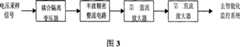
图3为本发明的电压检测电路的组成图。FIG. 3 is a composition diagram of the voltage detection circuit of the present invention.
具体实施方式Detailed ways
以下结合附图作进一步的详细描述:Further detailed description is made below in conjunction with accompanying drawing:
如图1所示,本发明由激励信号发生器、串联谐振功率放大电路、有源低通滤波器、可控直流电源、电压检测电路和电流检测电路构成。激励信号发生器的输出端接入到串联谐振功率放大电路的信号输入端。有源低通滤波器的输入端与智能化监控系统相连接,有源低通滤波器的输出端接入到可控直流电源的控制输入端。可控直流电源的电压输出端接至串联谐振功率放大电路的馈电输入端。串联谐振功率放大电路的信号输出端与负载的消融电极端相连,串联谐振功率放大电路的近地输出端与负载的引导电极端相连。电压检测电路的两个输入端中的一个直接并接于串联谐振功率放大电路的信号输出端,另一端则并接于串联谐振功率放大电路的共地端,电压检测电路的输出则加至智能化监控系统。电流检测电路的两个输入端中的一个并接于串联谐振功率放大电路的近地输出端,该端经取样电阻接至串联谐振功率放大电路的共地端,另一端同样并接于串联谐振功率放大电路的共地端,电流检测电路的输出同样加至智能化监控系统。As shown in Figure 1, the present invention is composed of an excitation signal generator, a series resonant power amplifier circuit, an active low-pass filter, a controllable DC power supply, a voltage detection circuit and a current detection circuit. The output end of the excitation signal generator is connected to the signal input end of the series resonant power amplifier circuit. The input end of the active low-pass filter is connected with the intelligent monitoring system, and the output end of the active low-pass filter is connected to the control input end of the controllable DC power supply. The voltage output terminal of the controllable DC power supply is connected to the feed input terminal of the series resonant power amplifier circuit. The signal output terminal of the series resonance power amplifier circuit is connected with the ablation electrode terminal of the load, and the near-ground output terminal of the series resonance power amplifier circuit is connected with the guide electrode terminal of the load. One of the two input terminals of the voltage detection circuit is directly connected to the signal output terminal of the series resonant power amplifier circuit, and the other terminal is connected to the common ground terminal of the series resonant power amplifier circuit in parallel, and the output of the voltage detection circuit is added to the intelligent monitoring system. One of the two input terminals of the current detection circuit is connected in parallel to the near-ground output terminal of the series resonant power amplifier circuit. The common ground terminal of the power amplifier circuit and the output of the current detection circuit are also added to the intelligent monitoring system.
所述的功率发生和监控电路明显具有:(一)在激励信号发生器形成的方波信号激励下,向负载提供射频功率,其大小直接取决于可控直流电源的输出电压,而它又为来自中央监控系统的脉冲宽度调制PWM信号所决定,达到功率控制的目的,摒弃了借改变激励信号的幅度来达到功率控制的传统做法,简单、精确。(二)串联谐振功率放大电路良好的选频特性可将方波激励信号转换成同频的正弦波输出信号,而其谐振特性可使输出的正弦波信号的幅度,在本实施例中,Uppmax≥500V,大大高于其漏极馈电电压,在本实施例中,Udmax≤60V,不象传统功率放大电路那样,输出信号的幅度总是低于漏极馈电电压,除非其使用升压变压器输出。(三)电压检测电路和电流检测电路均采用半波精密整流电路,采用峰峰值检测,而不是传统的有效值测量。其高精度检测保证了输出功率与负载阻抗的高测算精度,在本实施例中,对于额定负载,负载阻抗测算的相对误差δ≤2%。The power generation and monitoring circuit obviously has: (1) under the excitation of the square wave signal formed by the excitation signal generator, the radio frequency power is provided to the load, and its magnitude directly depends on the output voltage of the controllable DC power supply, and it is Determined by the pulse width modulation PWM signal from the central monitoring system, the purpose of power control is achieved, and the traditional method of achieving power control by changing the amplitude of the excitation signal is abandoned, which is simple and accurate. (2) The good frequency selection characteristics of the series resonant power amplifier circuit can convert the square wave excitation signal into a sine wave output signal of the same frequency, and its resonance characteristics can make the amplitude of the output sine wave signal, in the present embodiment, Uppmax ≥500V, much higher than its drain feed voltage, in this embodiment, Udmax≤60V, unlike traditional power amplifier circuits, the amplitude of the output signal is always lower than the drain feed voltage, unless it uses a boost Transformer output. (3) Both the voltage detection circuit and the current detection circuit use a half-wave precision rectification circuit, and use peak-to-peak detection instead of traditional effective value measurement. Its high-precision detection ensures high calculation accuracy of the output power and load impedance. In this embodiment, for the rated load, the relative error δ of load impedance measurement is ≤ 2%.
所述激励信号发生器包括主振、缓冲、分频、前置放大等基本电路,产生射频频率、具有一定功率电平,在本实施例中,射频频率F=461KHz,电压幅度Vp=6V,电流幅度Ip=0.3A的方波信号。The excitation signal generator includes basic circuits such as main vibration, buffering, frequency division, and preamplification, and generates radio frequency with a certain power level. In this embodiment, radio frequency F=461KHz, voltage amplitude Vp=6V, Square wave signal with current amplitude Ip=0.3A.
所述串联谐振功率放大电路应用调谐放大电路程式,使用VMOS场效应管作功率放大器件,工作在临界C类状态,输出采用LC串联谐振,负载并接在谐振电容上,漏极由可控直流电源馈电。其具体电路如图2所示:VMOS场效应管MOSFET-IRFP350的栅极由激励信号发生器激励,源极接地,漏极通过由滤波电感L2和第三滤波电容C3、第四滤波电容C4以及第五滤波电容C5组成的П型滤波电路与可控直流电源的电压输出端相接,漏极馈电电压为0~60V,漏极还与耦合电容C1相连。耦合电容C1的另一端与谐振电感L1相连,谐振电感L1的另一端与谐振电容C2相接,谐振电容C2的另一端接地,谐振电感L1、谐振电容C2构成串联谐振回路,其谐振频率为461KHz。负载与取样电阻R1串联后并接在谐振电容C2上,电压采样信号直接从谐振电容C2两端获得,电流采样信号则从取样电阻R1两端获得。谐振电容C2可以由多个电容并联组成,在本实施例中为8个电容并联,它们的电容量不尽相同。谐振电感L1可以由多个电感串联组成,在本实施例中为2个电感串联,它们的电感量相同。取样电阻R1可以由多个电阻并联组成,在实施例中为2个电阻并联,它们的电阻值相同。本发明利用串联谐振功率放大电路良好的选频特性将方波激励信号转换成同频的正弦波输出信号,而其谐振特性可使输出的正弦波信号的幅度,在本实施例中,Uppmax≥500V大大高于其漏极馈电电压,在本实施例中,Udmax≤60V。另一方面,由于VMOS场效应管MOSFET-IRFP350工作在临界C类状态,管子本身的功率损耗近乎为零,因而,工作效率很高。串联谐振功率放大电路的输出幅度直接取决于其漏极馈电电压,而不会随其输入幅度的变化而变化,本发明利用这一特性,通过控制馈电电压来达到控制其输出信号幅度的目的。The series resonant power amplifying circuit uses a tuned amplifying circuit program, uses a VMOS field effect transistor as a power amplifying device, works in a critical class C state, and uses an LC series resonant output, the load is connected to the resonant capacitor in parallel, and the drain is controlled by a DC power feed. Its specific circuit is shown in Figure 2: the gate of the VMOS field effect transistor MOSFET-IRFP350 is excited by the excitation signal generator, the source is grounded, and the drain passes through the filter inductor L2, the third filter capacitor C3, the fourth filter capacitor C4 and The П-shaped filter circuit formed by the fifth filter capacitor C5 is connected to the voltage output terminal of the controllable DC power supply, the drain feed voltage is 0-60V, and the drain is also connected to the coupling capacitor C1. The other end of the coupling capacitor C1 is connected to the resonant inductor L1, the other end of the resonant inductor L1 is connected to the resonant capacitor C2, the other end of the resonant capacitor C2 is grounded, the resonant inductor L1 and the resonant capacitor C2 form a series resonant circuit, and its resonant frequency is 461KHz . The load is connected in series with the sampling resistor R1 and connected to the resonant capacitor C2, the voltage sampling signal is directly obtained from both ends of the resonant capacitor C2, and the current sampling signal is obtained from both ends of the sampling resistor R1. The resonant capacitor C2 can be composed of multiple capacitors connected in parallel, in this embodiment, 8 capacitors are connected in parallel, and their capacitances are different. The resonant inductor L1 may be composed of multiple inductors connected in series, in this embodiment, two inductors connected in series, and their inductances are the same. The sampling resistor R1 can be composed of multiple resistors connected in parallel, in the embodiment, two resistors are connected in parallel, and their resistance values are the same. The present invention utilizes the good frequency selection characteristics of the series resonant power amplifier circuit to convert the square wave excitation signal into a sine wave output signal of the same frequency, and its resonance characteristics can make the amplitude of the output sine wave signal, in this embodiment, Uppmax≥ 500V is much higher than its drain feed voltage, in this embodiment, Udmax≤60V. On the other hand, since the VMOS field effect transistor MOSFET-IRFP350 works in the critical class C state, the power loss of the tube itself is almost zero, so the working efficiency is very high. The output amplitude of the series resonant power amplifier circuit directly depends on its drain feed voltage, and will not change with the change of its input amplitude. The present invention utilizes this characteristic to achieve the control of the output signal amplitude by controlling the feed voltage. Purpose.
所述有源低通滤波器由集成电路LM358及其外围电路构成,它接收来自智能化监控系统的脉冲宽度调制PWM信号,输出幅度可变的直流电压,在本实施例中为0-5V,到可控直流电源的控制输入端。可控直流电源采用开关直流稳压电源,可控直流电源的电压输出端接至串联谐振功率放大电路的馈电输入端,可控直流电源的输出电压随着加至可控直流电源输入端的控制电压的变化而变化。The active low-pass filter is composed of an integrated circuit LM358 and its peripheral circuits. It receives a pulse width modulation PWM signal from an intelligent monitoring system, and outputs a variable DC voltage, which is 0-5V in this embodiment. To the control input of the controllable DC power supply. The controllable DC power supply adopts a switching DC stabilized power supply. The voltage output terminal of the controllable DC power supply is connected to the feed input terminal of the series resonant power amplifier circuit. changes with changes in voltage.
输出电压随输入控制电压的变化而变化,在本实施例中,变化区间为0-60V。The output voltage varies with the input control voltage, and in this embodiment, the variation range is 0-60V.
所述电压检测电路的组成如图3所示,它由耦合隔离变压器、半波精密整流电路、第一直流放大器和第二直流放大器组成。耦合隔离变压器的初级直接并接在谐振电容C2的两端,第二直流放大器的输出送至智能化监控系统。其中的半波精密整流电路以比例放大器和整流二极管为核心,它采用峰峰值检测,而不是有效值检测。因为比例放大器带有深度负反馈,使得因二极管在小信号时的非线性和正向导电压降造成的误差基本上得以消除,再加上采用峰峰值检测,大大提高了检测精度。The composition of the voltage detection circuit is shown in Figure 3, which consists of a coupling isolation transformer, a half-wave precision rectifier circuit, a first DC amplifier and a second DC amplifier. The primary of the coupling isolation transformer is directly connected in parallel with both ends of the resonant capacitor C2, and the output of the second DC amplifier is sent to the intelligent monitoring system. The half-wave precision rectification circuit takes the proportional amplifier and rectifier diode as the core, and it uses peak-to-peak detection instead of effective value detection. Because the proportional amplifier has deep negative feedback, the error caused by the nonlinearity of the diode and the forward voltage drop in the small signal can be basically eliminated, and the peak-to-peak detection is adopted, which greatly improves the detection accuracy.
电流检测电路与电压检测电路相似,唯一的区别是两者所用的耦合隔离变压器的变比不一样,前者为1∶1,后者为100∶1。输出电压和输出电流的高精度实时检测,保证了射频消融治疗系统的输出功率和负载阻抗的测算精度,在本实施例中,对于额定负载,负载阻抗测算的相对误差δ≤2%,有效地保证了射频消融治疗系统疗效和安全。The current detection circuit is similar to the voltage detection circuit, the only difference is that the transformation ratio of the coupling isolation transformer used by the two is different, the former is 1:1, and the latter is 100:1. The high-precision real-time detection of the output voltage and output current ensures the measurement accuracy of the output power and load impedance of the radiofrequency ablation treatment system. In this embodiment, for the rated load, the relative error of load impedance measurement and calculation δ≤2%, effectively The curative effect and safety of the radiofrequency ablation treatment system are guaranteed.
Claims (5)
Priority Applications (1)
| Application Number | Priority Date | Filing Date | Title |
|---|---|---|---|
| CNB2004100530343ACN1305445C (en) | 2004-07-22 | 2004-07-22 | Power generating and monitoring circuit of radio frequency melting therapeutic system |
Applications Claiming Priority (1)
| Application Number | Priority Date | Filing Date | Title |
|---|---|---|---|
| CNB2004100530343ACN1305445C (en) | 2004-07-22 | 2004-07-22 | Power generating and monitoring circuit of radio frequency melting therapeutic system |
Publications (2)
| Publication Number | Publication Date |
|---|---|
| CN1586420A CN1586420A (en) | 2005-03-02 |
| CN1305445Ctrue CN1305445C (en) | 2007-03-21 |
Family
ID=34602714
Family Applications (1)
| Application Number | Title | Priority Date | Filing Date |
|---|---|---|---|
| CNB2004100530343AExpired - Fee RelatedCN1305445C (en) | 2004-07-22 | 2004-07-22 | Power generating and monitoring circuit of radio frequency melting therapeutic system |
Country Status (1)
| Country | Link |
|---|---|
| CN (1) | CN1305445C (en) |
Families Citing this family (14)
| Publication number | Priority date | Publication date | Assignee | Title |
|---|---|---|---|---|
| CN100457059C (en)* | 2005-07-12 | 2009-02-04 | 付洁宇 | Multi-path radio-frequency smelting therapic equipment |
| BRPI0621017A2 (en)* | 2005-12-06 | 2011-11-29 | St Jude Medical Atrial Fibrill Div | tissue ablation electrode junction evaluation |
| CN100457060C (en)* | 2006-05-19 | 2009-02-04 | 江苏天马高科技有限责任公司 | RF tumor treating equipment |
| CN103425166A (en)* | 2013-08-20 | 2013-12-04 | 成都成电光信科技有限责任公司 | Filtering and voltage stabilizing circuit |
| CN103462685B (en)* | 2013-09-13 | 2015-12-23 | 安徽奥弗医疗设备科技股份有限公司 | A kind of electric control gear for heat setting cutter |
| WO2016070009A1 (en)* | 2014-10-31 | 2016-05-06 | Medtronic Advanced Energy Llc | Power monitoring circuitry and method for reducing leakage current in rf generators |
| CN104473691B (en)* | 2014-12-30 | 2017-04-26 | 北京天助畅运医疗技术股份有限公司 | Power control system and power control method for radio frequency treatment equipment |
| CN105662575B (en)* | 2016-01-04 | 2019-04-16 | 浙江伽奈维医疗科技有限公司 | Radio frequency ablation device |
| CN108210063A (en)* | 2017-12-28 | 2018-06-29 | 上海交通大学 | Ultrasound-driven power monitoring apparatus |
| CN110160678A (en)* | 2019-06-21 | 2019-08-23 | 上海工业自动化仪表研究院有限公司 | Power amplification circuit for magnetoelastic sensor |
| CN112807072B (en)* | 2020-12-31 | 2022-12-20 | 杭州堃博生物科技有限公司 | Radio frequency generating circuit, device and method |
| CN113533845B (en)* | 2021-07-06 | 2023-03-31 | 加特兰微电子科技(上海)有限公司 | On-chip radio frequency power meter, chip, radio device and electronic equipment |
| CN113768612B (en)* | 2021-07-30 | 2023-12-22 | 苏州艾科脉医疗技术有限公司 | High voltage transmitting circuit for catheter and ablation instrument |
| CN119033457A (en)* | 2023-05-29 | 2024-11-29 | 武汉联影智融医疗科技有限公司 | Electrosurgical host, system, control method, storage medium and program product |
Citations (5)
| Publication number | Priority date | Publication date | Assignee | Title |
|---|---|---|---|---|
| CN2161271Y (en)* | 1993-03-15 | 1994-04-13 | 复旦大学 | Radiofrequency Ablation Therapy Apparatus |
| US5484400A (en)* | 1992-08-12 | 1996-01-16 | Vidamed, Inc. | Dual channel RF delivery system |
| US5542916A (en)* | 1992-08-12 | 1996-08-06 | Vidamed, Inc. | Dual-channel RF power delivery system |
| CN1308510A (en)* | 1998-05-08 | 2001-08-15 | 诺瓦塞普特 | RF generator for providing power to the ablation device |
| CN2543497Y (en)* | 2002-04-26 | 2003-04-09 | 河南华南医疗电子仪器有限公司 | Temp-controlling radio-freqnency radiation therapeutic instrument |
- 2004
- 2004-07-22CNCNB2004100530343Apatent/CN1305445C/ennot_activeExpired - Fee Related
Patent Citations (5)
| Publication number | Priority date | Publication date | Assignee | Title |
|---|---|---|---|---|
| US5484400A (en)* | 1992-08-12 | 1996-01-16 | Vidamed, Inc. | Dual channel RF delivery system |
| US5542916A (en)* | 1992-08-12 | 1996-08-06 | Vidamed, Inc. | Dual-channel RF power delivery system |
| CN2161271Y (en)* | 1993-03-15 | 1994-04-13 | 复旦大学 | Radiofrequency Ablation Therapy Apparatus |
| CN1308510A (en)* | 1998-05-08 | 2001-08-15 | 诺瓦塞普特 | RF generator for providing power to the ablation device |
| CN2543497Y (en)* | 2002-04-26 | 2003-04-09 | 河南华南医疗电子仪器有限公司 | Temp-controlling radio-freqnency radiation therapeutic instrument |
Also Published As
| Publication number | Publication date |
|---|---|
| CN1586420A (en) | 2005-03-02 |
Similar Documents
| Publication | Publication Date | Title |
|---|---|---|
| CN1305445C (en) | Power generating and monitoring circuit of radio frequency melting therapeutic system | |
| US8779852B2 (en) | Class resonant-H electrosurgical generators | |
| CN106411291B (en) | High-power adjustable high-frequency fractional order capacitor with order greater than 1 and control method thereof | |
| CN104259081B (en) | A kind of piezoelectric transducer frequency tracking method and system | |
| CN110297130B (en) | A DC/DC converter with fuel cell internal resistance measurement function and internal resistance measurement method | |
| CN104297657A (en) | Digitized high-power microwave diode reversed dynamic waveform and loss power testing system | |
| CN104901630B (en) | Realize the tunable radio frequency phase difference power amplification circuit of linear ablation | |
| CN111555625A (en) | Online monitoring device and method for output capacitor and secondary inductor of DCM flyback converter | |
| CN111682768A (en) | LCLCL High-Order DC Converter and Control Method Based on Stacked Bridge | |
| CN220325507U (en) | Interleaved parallel PFC self-adaptive current detection circuit under wide-area working condition | |
| CN111856145B (en) | Device and method for monitoring ESR and L of boost DC/DC converter | |
| CN114826208B (en) | Hybrid impedance matching topology and control method thereof | |
| CN1734912A (en) | An integrated power supply for short-pulse high-current laser drive | |
| CN101499779B (en) | Piezoelectric minimized wide-band power amplifier | |
| CN115085549A (en) | Impedance measurement device and measurement method based on interleaved parallel boost circuit | |
| CN106169753A (en) | Direct converter and the active filter of even-order harmonic modulation technique is handed over based on high-frequency isolation | |
| CN111293867B (en) | Direct current output circuit of stack AC ripple | |
| CN217282747U (en) | Automatic resonance high-voltage high-frequency alternating current power supply of capacitive load | |
| CN219871516U (en) | Circuit for sampling high-frequency voltage by using capacitance between PCB boards | |
| CN213342156U (en) | High-voltage power amplifier for piezoelectric ceramic vibration platform | |
| CN106443097A (en) | High frequency harmonic current generator | |
| CN213754455U (en) | A digital signal generator device | |
| Liu et al. | Design of a intellectualized ultrasonic generator | |
| CN112600413B (en) | Internal resistance observation method and internal resistance observer of DC-DC converter | |
| CN113572275B (en) | A chip-based resonant circuit |
Legal Events
| Date | Code | Title | Description |
|---|---|---|---|
| C06 | Publication | ||
| PB01 | Publication | ||
| C10 | Entry into substantive examination | ||
| SE01 | Entry into force of request for substantive examination | ||
| C14 | Grant of patent or utility model | ||
| GR01 | Patent grant | ||
| C17 | Cessation of patent right | ||
| CF01 | Termination of patent right due to non-payment of annual fee | Granted publication date:20070321 Termination date:20130722 |