CN1302375C - Editor device and recording medium for storing an editor program - Google Patents
Editor device and recording medium for storing an editor programDownload PDFInfo
- Publication number
- CN1302375C CN1302375CCNB2004100004386ACN200410000438ACN1302375CCN 1302375 CCN1302375 CCN 1302375CCN B2004100004386 ACNB2004100004386 ACN B2004100004386ACN 200410000438 ACN200410000438 ACN 200410000438ACN 1302375 CCN1302375 CCN 1302375C
- Authority
- CN
- China
- Prior art keywords
- data
- ladder
- mentioned
- program
- screen
- Prior art date
- Legal status (The legal status is an assumption and is not a legal conclusion. Google has not performed a legal analysis and makes no representation as to the accuracy of the status listed.)
- Expired - Lifetime
Links
- 238000000034methodMethods0.000claimsabstractdescription135
- 238000012545processingMethods0.000claimsdescription155
- 230000008569processEffects0.000claimsdescription89
- 230000009471actionEffects0.000claimsdescription7
- 230000001419dependent effectEffects0.000claimsdescription2
- 238000005538encapsulationMethods0.000claims1
- 238000010586diagramMethods0.000abstractdescription117
- 230000006870functionEffects0.000description148
- 238000003860storageMethods0.000description64
- 239000002131composite materialSubstances0.000description48
- 230000015654memoryEffects0.000description46
- 101100190617Arabidopsis thaliana PLC2 geneProteins0.000description36
- 101100408456Arabidopsis thaliana PLC8 geneProteins0.000description36
- 101100464304Caenorhabditis elegans plk-3 geneProteins0.000description36
- 101100093534Saccharomyces cerevisiae (strain ATCC 204508 / S288c) RPS1B geneProteins0.000description36
- 238000004891communicationMethods0.000description25
- 238000007726management methodMethods0.000description22
- 238000004458analytical methodMethods0.000description17
- 238000000605extractionMethods0.000description13
- 150000001875compoundsChemical class0.000description12
- 238000013461designMethods0.000description11
- 230000008676importEffects0.000description8
- 239000000284extractSubstances0.000description6
- 238000004364calculation methodMethods0.000description5
- 238000001514detection methodMethods0.000description5
- 239000000203mixtureSubstances0.000description5
- 238000012423maintenanceMethods0.000description4
- 239000000470constituentSubstances0.000description3
- 230000018109developmental processEffects0.000description3
- 238000012544monitoring processMethods0.000description3
- 230000003287optical effectEffects0.000description3
- 230000002441reversible effectEffects0.000description3
- 238000012546transferMethods0.000description3
- 238000006243chemical reactionMethods0.000description2
- 238000013523data managementMethods0.000description2
- 238000011161developmentMethods0.000description2
- 239000004973liquid crystal related substanceSubstances0.000description2
- 230000001343mnemonic effectEffects0.000description2
- 230000003068static effectEffects0.000description2
- 230000005540biological transmissionEffects0.000description1
- 230000008859changeEffects0.000description1
- 238000012937correctionMethods0.000description1
- 230000007547defectEffects0.000description1
- 238000003745diagnosisMethods0.000description1
- 238000012905input functionMethods0.000description1
- 230000009191jumpingEffects0.000description1
- 238000004519manufacturing processMethods0.000description1
- 238000005192partitionMethods0.000description1
- 238000003825pressingMethods0.000description1
- 238000009877renderingMethods0.000description1
- 239000004065semiconductorSubstances0.000description1
- 230000035939shockEffects0.000description1
- 230000008054signal transmissionEffects0.000description1
- 230000001360synchronised effectEffects0.000description1
- 230000033772system developmentEffects0.000description1
- 238000012360testing methodMethods0.000description1
- 230000000007visual effectEffects0.000description1
Images


Classifications
- G—PHYSICS
- G05—CONTROLLING; REGULATING
- G05B—CONTROL OR REGULATING SYSTEMS IN GENERAL; FUNCTIONAL ELEMENTS OF SUCH SYSTEMS; MONITORING OR TESTING ARRANGEMENTS FOR SUCH SYSTEMS OR ELEMENTS
- G05B19/00—Programme-control systems
- G05B19/02—Programme-control systems electric
- G05B19/04—Programme control other than numerical control, i.e. in sequence controllers or logic controllers
- G05B19/05—Programmable logic controllers, e.g. simulating logic interconnections of signals according to ladder diagrams or function charts
- G05B19/056—Programming the PLC
- G—PHYSICS
- G05—CONTROLLING; REGULATING
- G05B—CONTROL OR REGULATING SYSTEMS IN GENERAL; FUNCTIONAL ELEMENTS OF SUCH SYSTEMS; MONITORING OR TESTING ARRANGEMENTS FOR SUCH SYSTEMS OR ELEMENTS
- G05B19/00—Programme-control systems
- G05B19/02—Programme-control systems electric
- G05B19/04—Programme control other than numerical control, i.e. in sequence controllers or logic controllers
- G05B19/05—Programmable logic controllers, e.g. simulating logic interconnections of signals according to ladder diagrams or function charts
- G—PHYSICS
- G05—CONTROLLING; REGULATING
- G05B—CONTROL OR REGULATING SYSTEMS IN GENERAL; FUNCTIONAL ELEMENTS OF SUCH SYSTEMS; MONITORING OR TESTING ARRANGEMENTS FOR SUCH SYSTEMS OR ELEMENTS
- G05B2219/00—Program-control systems
- G05B2219/10—Plc systems
- G05B2219/11—Plc I-O input output
- G05B2219/1104—Display state of connection of I-O
- G—PHYSICS
- G05—CONTROLLING; REGULATING
- G05B—CONTROL OR REGULATING SYSTEMS IN GENERAL; FUNCTIONAL ELEMENTS OF SUCH SYSTEMS; MONITORING OR TESTING ARRANGEMENTS FOR SUCH SYSTEMS OR ELEMENTS
- G05B2219/00—Program-control systems
- G05B2219/10—Plc systems
- G05B2219/13—Plc programming
- G05B2219/13048—Display of ladder, RLD, RLL, KOP
- G—PHYSICS
- G05—CONTROLLING; REGULATING
- G05B—CONTROL OR REGULATING SYSTEMS IN GENERAL; FUNCTIONAL ELEMENTS OF SUCH SYSTEMS; MONITORING OR TESTING ARRANGEMENTS FOR SUCH SYSTEMS OR ELEMENTS
- G05B2219/00—Program-control systems
- G05B2219/10—Plc systems
- G05B2219/13—Plc programming
- G05B2219/13052—Display of ladder diagram
- G—PHYSICS
- G05—CONTROLLING; REGULATING
- G05B—CONTROL OR REGULATING SYSTEMS IN GENERAL; FUNCTIONAL ELEMENTS OF SUCH SYSTEMS; MONITORING OR TESTING ARRANGEMENTS FOR SUCH SYSTEMS OR ELEMENTS
- G05B2219/00—Program-control systems
- G05B2219/10—Plc systems
- G05B2219/13—Plc programming
- G05B2219/13144—GUI graphical user interface, icon, function bloc editor, OI operator interface
Landscapes
- Physics & Mathematics (AREA)
- General Physics & Mathematics (AREA)
- Engineering & Computer Science (AREA)
- Automation & Control Theory (AREA)
- Programmable Controllers (AREA)
- Stored Programmes (AREA)
- User Interface Of Digital Computer (AREA)
- Processing Or Creating Images (AREA)
Abstract
Description
Translated fromChinese本申请是原案申请号为00812266.0的发明专利申请(国际申请号:PCT/JP00/05803,申请日:2000年8月28日,发明名称:编辑装置及用于存储编辑程序的存储介质)的分案申请。This application is a branch of the invention patent application with the original application number 00812266.0 (international application number: PCT/JP00/05803, filing date: August 28, 2000, invention name: editing device and storage medium for storing editing programs) case application.
技术领域technical field
本发明涉及在具有可显示控制对象机器的状态的功能及控制控制对象机器的动作的功能的系统中,对根据控制对象机器状态的显示内容和控制对象机器状态的控制程序进行程序设计的编辑装置及用于存储编辑程序的存储介质。The present invention relates to an editing device for programming a control program based on the display content of the state of the controlled device and the state of the controlled device in a system having a function of displaying the state of the controlled device and a function of controlling the operation of the controlled device And a storage medium for storing the editing program.
背景技术Background technique
被称为PLC(以下简称PLC)的工业用控制装置,用于实现以顺序控制等各种控制,具有以CPU及内存为中心的硬件部分和进行控制的软件部分。软件部分包含:为了让PLC根据最初设计的控制系统进行动作所设计的顺序控制流程、向该控制流程指令的转换、将指令写入内存等。一般来说,这一连串的工作被称为程序设计。An industrial control device called PLC (hereinafter referred to as PLC) is used to realize various controls such as sequence control, and has a hardware part centered on a CPU and a memory, and a software part for control. The software part includes: the sequential control flow designed for the PLC to operate according to the originally designed control system, the conversion to the control flow instructions, and the writing of instructions into the memory, etc. Generally speaking, this series of work is called programming.
针对这样的程序设计,为了让不具有计算机专业知识的人也可以用独特的程序语言简单地生成程序,因此让用户容易使用的各种程序设计语言也就陆续被开发出来。现在,国际电气技术标准会议IEC(International ElectrotechnicalCommission)制定了标准的程序设计语言(IEC 6 1131-1)。即顺序式功能图SFC(Sequential Function Chart)、阶梯图LD(Ladder Diagram)、指令列表IL(Instruction List)、功能方块图FBD(Function Block Diagram)及结构化文本ST(Structured Text)五种语言。For such programming, various programming languages that are easy for users to use have been developed one after another in order to allow people without computer expertise to easily generate programs using unique programming languages. Now, the International Electrotechnical Commission IEC (International Electrotechnical Commission) has developed a standard programming language (IEC 6 1131-1). That is, SFC (Sequential Function Chart), ladder diagram LD (Ladder Diagram), instruction list IL (Instruction List), function block diagram FBD (Function Block Diagram) and structured text ST (Structured Text) five languages.
如上所述,利用各种程序设计语言来开发程序的环境也正在完善当中。例如,对于阶梯图来说,由于用中继符号(relay symbol)设计阶梯电路比较简单,因此从以前开始就被广泛使用,至目前为止也算是最常使用的程序设计语言。作为在用这种程序设计语言进行程序设计工作中使用的程序设计工具,阶梯编辑器(ladder Editor)等的程序设计软件已渐渐普及。由于该软件用于个人计算机等的计算机装置上时,可以将阶梯图等用包含符号(symbol)的形态作成,因此可以简单地进行程序生成或编辑。As described above, environments for developing programs using various programming languages are also being developed. For example, for the ladder diagram, since it is relatively simple to design a ladder circuit with a relay symbol, it has been widely used from the past, and it is still the most commonly used programming language so far. Programming software such as a ladder editor has become popular as a programming tool used in programming work using this programming language. When this software is used on a computer device such as a personal computer, it is possible to create a ladder diagram or the like in a form including symbols, so that program creation and editing can be easily performed.
另外,作为人机接口HMI(Human Machine Interface)机器的可编程显示器,是像素显示画面、操作用输入开关、主控制器(PLC)的接口,并具有诸如用于控制画面上的操作输入的程序内存的操作用显示器。一般来说,可编程显示器,由于进行图形显示,所以除了具有操作盘、开关、显示灯等功能以外,还具有对用来管理控制对象机器的运行状况和工作指示等的各种监视器、对机器输入设定值的终端的功能。In addition, a programmable display as a human-machine interface HMI (Human Machine Interface) machine is a pixel display screen, an input switch for operation, an interface to the main controller (PLC), and has programs such as Display for memory operation. Generally speaking, because of the graphic display, the programmable display not only has the functions of operation panel, switch, display lamp, etc., but also has various monitors for managing the operating status and work instructions of the controlled machine, and for The function of the terminal for inputting the set value of the machine.
另外,近年来出现了通过搭载用来与控制对象机器连接的输入输出单元而具有PLC的控制功能的可编程显示器。Moreover, the programmable display which has the control function of PLC by mounting the input-output unit for connecting with the control target apparatus appeared in recent years.
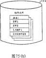
这样的可编程显示器所显示的控制画面(显示内容程序),可由用户使用画面作成软件(画面作成编辑器)自行作成。当用户自行作成画面时,使用在个人计算机等中由画面作成软件所提供的开关、灯、数值键盘、仪表显示器、图表显示器等组件(图标)或者绘制功能等,构建自己想要的控制画面。The control screen (display content program) displayed on such a programmable display can be created by the user himself using screen creation software (screen creation editor). When the user creates the screen by himself, he constructs the control screen he wants by using components (icons) such as switches, lamps, numeric keypads, meter displays, and graph displays provided by the screen creation software on a personal computer or the like, or drawing functions.
另外,监控用软件SCADA(监督控制和数据取得Supervisory Control AndData Acquisition)作为提供人机界面环境而普及。SCADA是一种显示机械的运转动作和控制盘的操作面板的高性能图形监视软件,与前述的画面作成编辑器相同,可利用基本图形的绘制功能和预先准备的组件作成控制画面。In addition, monitoring software SCADA (Supervisory Control and Data Acquisition) is popular as an environment for providing a human-machine interface. SCADA is a high-performance graphics monitoring software that displays the operation of the machine and the operation panel of the control panel. Like the aforementioned screen creation editor, it can use the basic graphics drawing function and pre-prepared components to create a control screen.
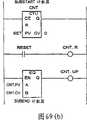
另外,画面作成编辑器并不只有上述的单一功能,其中也准备了复合多个功能的复合组件。作为复合组件,可列举出复合开关和计数器。复合开关,例如,由组合多个开关构成,具有根据需要与开关的动作同步的灯。另外,计数器具有分别显示设定值和计数值的数值显示器、计数完了时点亮的灯、用于复位操作的按钮等。这样的复合组件通常来说,已事先以库(Library)的形式登录,使用户可以在画面作成编辑器的窗口上自由选择。In addition, the screen creation editor does not only have the above-mentioned single function, but also prepares a compound component that combines multiple functions. As composite components, composite switches and counters can be cited. A composite switch is, for example, composed of a combination of a plurality of switches, and has lamps synchronized with the operation of the switches as necessary. In addition, the counter has a numerical display for separately displaying a set value and a counted value, a lamp that lights up when counting is completed, a button for reset operation, and the like. Such composite components are usually registered in advance as a library, and the user can freely select them on the window of the screen creation editor.
作成的控制画面,被作为画面数据传送到可编程显示器并存储。当PLC在运转时,可编程显示器根据与PLC之间互换的数据,并对应控制对象机器的动作状态,在控制画面上显示各组件和图形。The created control screen is sent to the programmable display as screen data and stored. When the PLC is running, the programmable display will display various components and graphics on the control screen according to the data exchanged with the PLC and corresponding to the operating state of the controlled object machine.
可是,一般来说用阶梯编辑器(ladder editor)等生成控制步骤程序(程序设计)和用画面作成编辑器生成显示内容程序(画面作成)是独立进行的。举例来说,如根据所生成的控制步骤程序而生成显示内容程序时,生成控制步骤程序时,须将关于各个设备所输入的名称及地址以表格形式记下来作为设计资料。边参照该设计资料边进行包含定义I/O地址等的显示内容程序的生成。另外,根据生成的显示内容程序而生成控制步骤程序时,也是同样根据预先准备的设计资料来进行。However, in general, creation of a control procedure program (program design) using a ladder editor or the like and creation of a display content program (screen creation) using a screen creation editor are performed independently. For example, when generating a display content program based on the generated control procedure program, when generating the control procedure program, it is necessary to write down the names and addresses entered for each device in a table form as design data. Create a program including display contents such as defining I/O addresses while referring to the design data. In addition, when the control procedure program is generated based on the generated display content program, it is also performed based on previously prepared design documents.
然而,这种装置必须事先准备与生成的程序建立对应关系的设计资料,因此有工作效率低的缺点。另外,上述的装置中,程序的生成全部都是通过用户的输入操作来进行,因此,上述的程序生成装置存在工作效率低且生成程序费时的问题。However, this kind of device has the disadvantage of low work efficiency because design data corresponding to the generated program must be prepared in advance. In addition, in the above-mentioned device, the generation of the program is all performed by the user's input operation. Therefore, the above-mentioned program generation device has the problems of low work efficiency and time-consuming generation of the program.
程序的生成全都是通过用户的输入操作而进行,因此,一个程序生成后再生成另一个程序时,边参照设计资料而进行的输入操作,恐怕会发生输入错误的情形。另外,发生这样的错误时,存在会增加程序的除错(debug)工作的问题。而且,由于用于生成显示内容程序所进行的输入工作和用于生成控制步骤程序所进行的输入工作两者须分别进行,因而需要大量的时间和劳力。All programs are generated through user input operations. Therefore, when one program is generated and then another program is generated, input operations while referring to design data may cause input errors. In addition, when such an error occurs, there is a problem that the debugging (debug) work of the program will be increased. Also, since both the input work for creating the display content program and the input work for creating the control procedure program have to be performed separately, much time and labor are required.
另外,在上述的程序生成装置中,由于虽然两个程序对应共通的设备而分别生成,但仍是分别生成,因而需另外进行用于分配设备的地址(I/O地址)和阶梯指令及组件的输入操作。In addition, in the above-mentioned program generation device, although the two programs are generated separately corresponding to the common equipment, they are still generated separately, so the address (I/O address) and ladder instructions for assigning the equipment and components need to be separately executed. input operation.
作为解决这方面的缺点而作出的发明,日本国特许公开公报11-175326号(1999年7月2日公开)中公布了可将作成阶梯图(阶梯程序)的阶梯编辑器和作成画面的画面作成编辑器之间的阶梯记号(阶梯指令)和配置在画面上的组件(图标)建立对应关系的编辑装置。该编辑装置可将阶梯窗口上显示的阶梯记号移至画面作成窗口。例如,通过拖曳,对于一个符号(symbol)及对应此符号的最少一个的记号,将包含共通的控制对象机器的名称及地址的属性数据存储在共通的数据库的同时,参照该属性数据,在画面作成窗口上显示与上述被拖曳的符号建立对应关系的记号。另外,这个编辑装置也可以进行相反的动作。因此先将阶梯图或画面中的一方作成,根据其用户进行拖曳等操作即可简单地作成另一方。As an invention made to solve this shortcoming, Japanese Patent Laid-Open Publication No. 11-175326 (published on July 2, 1999) discloses a ladder editor and a screen for creating a ladder diagram (ladder program) Create an editing device that associates ladder symbols (ladder instructions) between editors with components (icons) placed on the screen. This editing device can move the ladder mark displayed on the ladder window to the screen creation window. For example, by dragging, for one symbol (symbol) and at least one mark corresponding to the symbol, attribute data including the name and address of the common control target device are stored in the common database, and the attribute data is referred to, and displayed on the screen. A mark corresponding to the dragged symbol is displayed on the creation window. In addition, this editing device can also perform the reverse operation. Therefore, one of the ladder diagram or the screen is created first, and the other can be easily created by dragging and other operations according to the user.
然而,上述公报中所公布的编辑装置,虽然通过使数据共通化能避免阶梯编辑器和画面作成编辑器间重复数据的再次输入,但是必须分别设置用于存储属性数据的共通数据库和阶梯编辑器用的阶梯文件及画面作成辑器用的画面文件。而且,在将作成的阶梯图(用户程序)及画面(用户画面)登录到最终的阶梯文件及画面文件时,由于两个文件都存储上述的属性数据,造成属性数据的重复登录。However, in the editing device disclosed in the above publication, although the re-input of duplicate data between the ladder editor and the screen creation editor can be avoided by making the data common, a common database for storing attribute data and a database for the ladder editor must be separately provided. Ladder file and screen file for screen editor. Moreover, when registering the created ladder diagram (user program) and screen (user screen) into the final ladder file and screen file, both files store the above-mentioned attribute data, resulting in duplicate registration of attribute data.
另外,由于属性数据可从共通数据库中复制到阶梯文件或画面文件,在使阶梯文件和画面文件共享外部系统的数据时,必须经过从外部系统将数据复制到共通数据库中后,再将其复制到阶梯文件或画面文件的步骤。In addition, since the attribute data can be copied from the common database to the ladder file or the screen file, when the ladder file and the screen file share the data of the external system, the data must be copied from the external system to the common database before copying it. Step to ladder file or screen file.
这样,现有的编辑装置,因为数据由专门的文件来管理,因此存在不能有效利用数据库的缺点。In this way, the existing editing apparatus has a disadvantage that the database cannot be effectively used because the data is managed by a dedicated file.
另外,在用阶梯编辑器作成的阶梯图中,为了使阶梯图更容易看懂。例如,在如图84(a)所示的阶梯记号的旁边,将该阶梯记号所对应的控制对象机器(例如,开关和灯)的名称或动作、说明等一起注明。通常这种阶梯记号的附带信息是通过在阶梯编辑器分配地址给所输入的阶梯记号时,和地址一起分配给阶梯记号来输入的。In addition, in the ladder diagram created with the ladder editor, in order to make the ladder diagram easier to understand. For example, next to a step mark as shown in FIG. 84( a ), the name, operation, description, etc. of the controlled device (for example, a switch and a lamp) corresponding to the step mark are indicated together. Usually, such incidental information of ladder symbols is input by assigning addresses to the ladder symbols together with addresses when the ladder editor assigns addresses to the input ladder symbols.
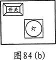
另一方面,在用画面作成编辑器作成的画面中,如图84(b)所示,也能够在对应控制对象机器所绘制的组件(例如,开关和灯)上,粘贴并显示关于该组件的附带信息。这样的附带信息,在画面作成编辑器将对应上述地址的组件配置到基础(base)画面时,一起与地址建立关联关系后输入。On the other hand, on the screen created with the screen creation editor, as shown in FIG. 84(b), it is also possible to paste and display information about the components (such as switches and lamps) drawn corresponding to the control target equipment. with additional information. Such incidental information is entered in association with the address when the screen creation editor arranges the component corresponding to the above-mentioned address on the base screen.
然而,这样的装置中,由于附带信息由阶梯编辑器和画面作成编辑器分别输入,需输入的附带信息越多,所需花费的时间和劳力也就越多。另外,因为一面参照对应一方程序的设计资料一面将附带信息写入另一方程序,可能会发生附带信息输入错误,而由于输入错误会使程序除错工作更加困难。并且,对应生成的程序的设计资料须事先准备,因此存在工作效率低的缺点。However, in such a device, since the incidental information is input separately by the ladder editor and the screen creation editor, the more incidental information to be input, the more time and effort are required. In addition, since the incidental information is written into the other program while referring to the design data of the corresponding one program, input errors of incidental information may occur, and the program debugging work is more difficult due to input errors. Moreover, the design data corresponding to the generated program must be prepared in advance, so there is a disadvantage of low work efficiency.
另外,上述的编辑装置,虽然可同时作成阶梯图和画面,但因效率不高,通常最好采用先作成阶梯图或先作成画面后再作成另一方的顺序。因此,上述的装置并不适用于同时作成阶梯图和画面的情况。因此,根据作成的阶梯图或画面来作成另一方时,在须更改阶梯指令和更改图标的情形下,须先将已生成的程序(阶梯图或画面)进行修改,因而造成程序设计效率低的缺点。In addition, although the above-mentioned editing device can create the ladder diagram and the screen at the same time, because the efficiency is not high, it is usually preferable to use the order of creating the ladder diagram first or the screen before creating the other. Therefore, the above-mentioned device is not suitable for the situation of creating a ladder diagram and a screen at the same time. Therefore, when creating the other side based on the created ladder diagram or screen, if the ladder instructions and icons need to be changed, the generated program (ladder diagram or screen) must first be modified, resulting in low program design efficiency. shortcoming.
而且,上述的编辑装置,先将在一方编辑器中输入的关于阶梯指令和图标等的数据作为程序登录到文件中,再利用该数据作成另一方程序。因此,无法做到预先将共通于两个程序的数据作成,再根据该数据来作成一方程序或两方的程序。Furthermore, the above-mentioned editing device first registers the data on the ladder instructions, icons, etc. input in one editor into a file as a program, and then uses the data to create the other program. Therefore, it is impossible to create data common to both programs in advance, and then create one program or both programs based on the data.
并且,上述的编辑装置,根据已作成的画面作成阶梯图时,针对一个图标虽可自动生成一个阶梯指令,但是针对前述的复合组件,无法组合多个阶梯指令来自动生成最合适的阶梯电路。Furthermore, the above-mentioned editing device can automatically generate one ladder instruction for one icon when creating a ladder diagram based on the created screen, but cannot automatically generate the most suitable ladder circuit by combining multiple ladder instructions for the aforementioned composite component.
另外,上述的编辑装置,在将阶梯程序及用户画面的共通数据(设备名,地址等)复制到画面作成编辑器时,每次拖曳和拖放操作只能将一个阶梯记号拖曳和拖放至画面作成窗口,因而存在处理效率低的问题。另外,用这样的装置,由于用户重复将阶梯记号从阶梯窗口拖曳和拖放至画面作成窗口,恐怕会发生部分阶梯记号没有被拖曳到的误操作。In addition, in the editing device described above, when copying common data (device name, address, etc.) The screen is created as a window, so there is a problem of low processing efficiency. In addition, with such a device, since the user repeatedly drags and drops step marks from the step window to the screen creation window, there may be a possibility of erroneous operation that some step marks are not dragged.
发明内容Contents of the invention
本发明的目的是提供具有推持现有编辑装置中,可避免数据的重复输入的操作性的同时,又可有效利用数据库,且可容易地实现和外部系统的数据共享的编辑装置及存储编辑程序的存储介质。另外,本发明的目的为提供附带信息输入简易化,可更高效地生成显示内容程序及控制步骤程序的编辑装置及存储编辑程序的存储介质。The object of the present invention is to provide an editing device and a storage editor that can effectively utilize the database and easily realize data sharing with an external system while avoiding the operability of repeated input of data in an existing editing device. program storage medium. Another object of the present invention is to provide an editing device that simplifies the input of incidental information and can more efficiently create a display content program and a control procedure program, and a storage medium that stores the edited program.
本发明与现有的编辑装置相同可简易地生成程序,且更加适用于对应多样的生成方式。另外,本发明适用于在生成显示内容程序时,根据所输入的复合组件自动地生成控制步骤程序。并且,本发明适用于根据控制步骤程序的信息无误操作地高效率地生成显示内容程序。The present invention can easily generate programs similarly to existing editing devices, and is more suitable for various generation methods. In addition, the present invention is suitable for automatically generating a control procedure program based on an input composite component when generating a display content program. In addition, the present invention is suitable for efficiently generating a display content program without erroneous operations based on the information of the control procedure program.
(1)为了达到上述目的,本发明的编辑装置包含下列装置:第一编辑装置:生成显示内容程序,该显示内容程序用于确定显示控制对象机器状态的显示内容;第二编辑装置:生成用于确定控制上述对象机器的控制步骤的控制步骤程序;数据复制装置:将上述显示内容程序与上述控制步骤程序之间共通的数据,在存储上述显示内容程序的显示内容程序文件与存储上述控制步骤程序的控制步骤程序文件之间进行复制,上述数据复制装置,将在上述显示内容程序或上述控制步骤程序与由CAD生成的图记号之间共通的数据,从CAD数据库将上述数据复制到上述显示内容程序文件或上述控制步骤程序文件中。(1) In order to achieve the above object, the editing device of the present invention includes the following devices: a first editing device: generate a display content program, and the display content program is used to determine the display content for displaying the state of the machine to be controlled; The control procedure program for determining the control procedure for controlling the above-mentioned object device; the data reproduction device: the data common between the above-mentioned display content program and the above-mentioned control procedure program is stored in the display content program file storing the above-mentioned display content program and storing the above-mentioned control procedure The control procedure of the program is copied between program files, and the data copying device copies the data common between the display content program or the control procedure program and the drawing symbols generated by CAD from the CAD database to the display In the content program file or the above-mentioned control step program file.
本发明的存储介质,为了达到前述的目的,存储包含在计算机上分别实现上述第一及第二编辑装置和上述的数据复制装置的第一及第二编辑器处理和数据复制处理的编辑程序。In order to achieve the aforementioned object, the storage medium of the present invention stores an editing program including the first and second editor processing and data copying processing of the first and second editing devices and the data copying device respectively implemented on a computer.
另外,本发明的另一存储介质,存储包含上述第一或第二编辑器处理中的任何一方和上述数据复制处理的编辑程序。根据这个存储介质,包含第一或第二编辑器处理的任何一方和数据复制处理的2种编辑程序,也就是说,可以提供第一编辑程序或第二编辑程序。In addition, another storage medium of the present invention stores an editing program including either one of the above-mentioned first or second editor processing and the above-mentioned data copy processing. According to this storage medium, two kinds of editing programs, either one of the first or second editor processing and data copy processing, can be provided, that is, the first editing program or the second editing program can be provided.
上述的构成中,由第一编辑装置(第一编辑器处理)生成的显示内容程序存储在显示内容程序文件中,由第二编辑装置(第二编辑器处理)生成的控制步骤程序存储在控制步骤程序文件中。另外,通过第一编辑装置(第一编辑器处理)的操作生成显示内容程序后或生成显示内容程序时,通过第二编辑装置(第二编辑器处理)的操作来生成控制步骤程序时,利用数据的复制装置,在两个文件之间复制两个程序间共通的数据。另一方面,通过第二编辑装置(第二编辑器处理)的操作生成控制步骤程序后或生成控制程序时,通过第一编辑装置(第一编辑器处理)的操作生成显示内容程序时,利用数据的复制装置,在两个文件之间复制两个程序间共通的数据。In the above configuration, the display content program generated by the first editing device (first editor processing) is stored in the display content program file, and the control procedure program generated by the second editing device (second editor processing) is stored in the control file. step program file. In addition, when creating a display content program by the operation of the first editing device (first editor processing) or when creating a display content program, and creating a control procedure program by operating the second editing device (second editor processing), use The data copying device copies the common data between two programs between two files. On the other hand, after the control procedure program is generated by the operation of the second editing device (second editor processing) or when the control program is generated, when the display content program is generated by the operation of the first editing device (first editor processing), use The data copying device copies the common data between two programs between two files.
这样,由于存储在一方文件中的数据被复制到另一方文件,因此可以作成两个文件之间共通的数据库。其结果,也就没有必要作成两个编辑装置(两个编辑器处理)共通的数据库。而且,可避免两个编辑装置的数据重复输入。进而,通过将数据一起复制,可提高处理效率。In this way, since the data stored in one file is copied to the other file, it is possible to create a database common to both files. As a result, there is no need to create a common database for two editing devices (processing by two editors). Also, duplication of data input by two editing devices can be avoided. Furthermore, by copying data together, processing efficiency can be improved.
上述的编辑装置及存储介质中,最好与被复制上述数据的一方上述文件对应的上述第一或第二编辑装置(第一或第二编辑器处理),通过参照被复制的上述数据,来显示与数据关联的图像块。In the above-mentioned editing device and storage medium, it is preferable that the first or second editing device (first or second editor processing) corresponding to the file on which the data is copied refers to the copied data to Displays the image blocks associated with the data.
上述的构成中,通过数据复制装置(数据复制处理),在将数据从显示内容程序文件复制到控制步骤程序文件时,第二编辑装置(第二编辑器处理)通过参照被复制的数据,显示与该数据关联的图像块。另一方面,通过数据复制装置(数据复制处理),在将数据从控制步骤程序文件复制到显示内容程序文件时,第一编辑装置(第一编辑器处理)通过参照被复制的数据,显示与该数据关联的图像块。因此,可以在复制数据的同时显示图像块。In the above configuration, when data is copied from the display content program file to the control procedure program file by the data copying means (data copying process), the second editing means (second editor process) refers to the copied data to display The image block associated with this data. On the other hand, when data is copied from the control procedure program file to the display content program file by the data copying means (data copying process), the first editing means (first editor process) displays and The image block associated with this data. Therefore, image blocks can be displayed while copying data.
另外,上述数据复制装置(数据复制处理)最好在选择一方编辑装置的编辑器画面上显示的图像块并将其复制到另一方编辑装置的编辑器画面上的复制操作之前,复制上述数据。由此,例如根据已生成的程序来作成另一方程序时,预先将数据一起进行复制后,显示图标或符号。In addition, the data copying device (data copying process) preferably copies the data before copying an image block displayed on the editor screen of one editing device and copying it to the editor screen of the other editing device. In this way, for example, when another program is created from an already generated program, the data is copied together in advance, and an icon or symbol is displayed.
上述任何一个构成的编辑装置及存储介质中,最好上述数据复制装置(数据复制处理)将上述显示内容程序或上述控制步骤程序与上述应用程序之间共通的数据,复制到上述显示内容程序文件或上述控制步骤程序文件中。由此,显示内容程序文件或控制步骤程序文件,能够读取CAD等应用程序的数据。因此,通过利用两个程序文件所构建的数据库以外的数据库,能够更高效地开发程序,同时可将程序开发作为更大系统开发的一部分来组入。In the editing device and the storage medium having any one of the configurations above, it is preferable that the data copying means (data copying process) copies data common between the display content program or the control procedure program and the application program to the display content program file. Or in the above control step program file. Thereby, the display content program file or the control procedure program file can read the data of the application program such as CAD. Therefore, by using a database other than the database constructed by the two program files, the program can be developed more efficiently, and the program development can be incorporated as a part of larger system development.
上述的任何一个构成的编辑装置中,最好通过网络与其它系统连接,上述数据复制装置在上述两个文件与上述系统之间进行数据复制。这样,可将数据从系统直接复制到上述两个文件中的任何一方。所以,可容易地实现和外部系统的数据共享。In any one of the above-mentioned editing devices, it is preferable that it is connected to other systems through a network, and that the data copying device copies data between the two files and the above-mentioned system. In this way, data can be copied directly from the system to either of the two files mentioned above. Therefore, data sharing with external systems can be easily realized.
(2)为了达到上述的目的,本发明的编辑装置,包含下列装置:上述第一及第二编辑装置;数据合并装置,将上述显示内容程序中固有的画面数据、上述控制步骤程序中固有的控制数据、和上述显示内容程序与上述控制步骤程序共同包含的、包括与各控制对象机器对应地设定的变量名的变量数据合并存储为一个文件,在该文件中建立数据库,通过上述变量数据将上述显示内容程序与上述控制步骤程序相关联地进行统一管理;以及数据生成装置,根据从上述文件检索得到的上述变量数据的上述变量名,使上述第一编辑装置生成上述画面数据中所包含的显示符号的数据,同时使上述第二编辑装置生成上述控制数据中所包含的控制符号的数据。(2) In order to achieve the above-mentioned purpose, the editing device of the present invention includes the following devices: the above-mentioned first and second editing devices; The control data and the variable data contained in the above-mentioned display content program and the above-mentioned control procedure program together, including the variable names set corresponding to each control target machine, are combined and stored as one file, and a database is established in this file. Through the above-mentioned variable data The above-mentioned display content program and the above-mentioned control procedure program are collectively managed; and the data generating means causes the above-mentioned first editing means to generate The data of the display symbol, and at the same time cause the second editing device to generate the data of the control symbol included in the control data.
为了达到前述的目的,本发明的存储介质存储包含在计算机上分别执行上述第一及第二编辑装置、上述数据生成装置的第一及第二编辑器处理、数据生成处理的编辑程序。In order to achieve the aforementioned object, the storage medium of the present invention stores an editing program including the first and second editor processing and data generating processing of the first and second editing devices and the data generating device respectively executed on a computer.
另外,本发明的另一存储介质,存储包含上述第一或第二编辑器处理的任何一方、上述数据生成处理的编辑程序。根据这个存储介质,包含第一或第二编辑器处理中的任何一方和数据生成处理2种编辑程序,也就是说可以提供第一或第二编辑程序。In addition, another storage medium of the present invention stores an editing program including either one of the above-mentioned first or second editor processing and the above-mentioned data generation processing. According to this storage medium, two kinds of editing programs, either one of the first or second editor processing and data generation processing, are included, that is, the first or second editing program can be provided.
上述的构成中,通过第一编辑装置的操作在生成显示内容程序后或生成显示内容程序时,在通过第二编辑装置(第二编辑器处理)的操作生成控制步骤程序时,通过数据生成装置(数据生成处理),第二编辑装置(第二编辑器处理)根据包含变量数据的共通数据来生成固有数据。另一方面,通过第二编辑装置(第二编辑器处理)的操作在生成控制步骤程序后或生成控制步骤程序时,通过第一编辑装置(第一编辑器处理)的操作生成显示内容程序时,通过数据的生成装置(数据的生成处理),第一编辑装置(第一编辑器处理)根据包含变量数据的共通数据来生成固有数据。由此,可避免两个编辑装置(两个编辑器处理)重复输入数据。另外,共通数据通过包含变量名,可以使用诸如对应控制对象机器的符号、操作指示、控制对象机器的动作状态等事件名作为变量名。In the above-mentioned configuration, after the display content program is generated by the operation of the first editing device or when the display content program is generated, when the control procedure program is generated by the operation of the second editing device (second editor processing), the data generating device (Data generation processing), the second editing device (second editor processing) generates unique data from common data including variable data. On the other hand, when the control procedure program is generated by the operation of the second editing device (second editor processing) or when the control procedure program is generated, when the display content program is generated by the operation of the first editing device (first editor processing) , the first editing means (first editor process) generates the unique data from the common data including the variable data by the data generating means (data generating process). Thereby, duplication of data input by two editing devices (two editor processes) can be avoided. In addition, the common data includes variable names, and event names such as symbols corresponding to controlled devices, operation instructions, and operating states of controlled devices can be used as variable names.
另外,上述的文件构成中,由于两个符号数据通过变量名结合,因此,可以容易地构建结合不同数据的各种数据库。例如,不仅可以构建目前广泛普及的容易使用的关系数据库、而且可以构建层次型数据库、网络型数据库、对象指向型数据库。因此,可更有效地利用数据库。In addition, in the file structure described above, since two symbol data are combined by variable names, it is possible to easily construct various databases combining different data. For example, it is possible to construct not only the widely popular and easy-to-use relational databases, but also hierarchical databases, network databases, and object-oriented databases. Therefore, the database can be utilized more efficiently.
上述的编辑装置及存储介质中,最好上述数据生成装置随着选择一方编辑装置的编辑器画面上显示的图像块并将其复制到另一方编辑装置的编辑器画面上的操作,来生成上述固有数据。In the editing device and storage medium described above, it is preferable that the data generating device generates the image block displayed on the editor screen of one editing device and copies it to the editor screen of the other editing device to generate the inherent data.
由此,通过第一编辑装置的操作在生成显示内容程序后或生成显示内容程序时,在通过第二编辑装置的操作生成控制步骤程序时,第二编辑装置通过数据生成装置,随着选择第一编辑装置的编辑器画面上的图像块并将其复制到第二编辑装置的编辑器画面上的操作,根据共通数据生成固有数据。Thus, when the control procedure program is generated by the operation of the second editing device after or when the display content program is generated by the operation of the first editing device, the second editing device selects the second editing device through the data generating device. An operation of editing an image block on an editor screen of one editing device and copying it to an editor screen of a second editing device generates unique data based on common data.
另一方面,通过第二编辑装置的操作在生成控制步骤程序后或生成控制步骤程序时,通过第一编辑装置的操作生成显示内容程序时,第一编辑装置通过数据生成装置,随着选择第二编辑装置的编辑器画面上的图像块并将其复制到第一编辑装置的编辑器画面上的操作,根据共通数据生成固有数据。由此,可避免两个编辑装置重复输入数据。On the other hand, when the display content program is generated by the operation of the first editing device after the control procedure program is generated or when the control procedure program is generated by the operation of the second editing device, the first editing device selects the second editing device through the data generating device. An operation of editing an image block on the editor screen of the second editing device and copying it to the editor screen of the first editing device generates unique data based on the common data. Thus, duplication of data input by two editing devices can be avoided.
另外,在这个编辑装置及存储介质中,最好包含数据合并装置(数据结合处理),该数据合并装置将下述数据中的两个符号数据分别经由上述变量名与下述变量数据结合,所述数据为:包含上述控制对象机器的地址及对应其所设定的上述变量名的作为上述共通数据的变量数据;包含控制符号(作为表示对应上述控制对象机器的控制动作的上述图像块)及其对应的上述变量名的作为固有数据的控制符号数据;和包含显示符号(作为表示上述控制对象机器及其状态的上述图像块)及其对应的上述变量名的作为上述固有数据的显示符号数据。In addition, the editing device and the storage medium preferably include data combining means (data combining processing) for combining two symbol data in the following data with the following variable data through the above-mentioned variable names, so Said data is: the variable data including the address of the above-mentioned control object machine and the above-mentioned variable name corresponding to it as the above-mentioned common data; Control symbol data as inherent data of the above-mentioned variable name corresponding to it; and display symbol data as the above-mentioned inherent data including a display symbol (as the above-mentioned image block representing the above-mentioned controlled device and its state) and the corresponding variable name .
在这样的构成中,由于通过数据合并装置(数据合并处理),两个符号数据通过变量名结合,因此,能够容易地构建结合各种不同数据的数据库。例如,不仅可以构建广泛普及又容易使用的关系数据库,而且可以构建层次型数据库、网络型数据库、对象指向型数据库等。因此,可更有效地利用数据库。In such a configuration, since two symbol data are combined by variable names by the data combining means (data combining process), it is possible to easily construct a database combining various different data. For example, not only a widely popular and easy-to-use relational database can be constructed, but also hierarchical databases, network databases, and object-oriented databases can be constructed. Therefore, the database can be utilized more efficiently.
(3)为了达到上述目的,本发明的编辑装置,在(2)的编辑装置中包含附带信息提供装置,该附带信息提供装置将对应各控制对象机器的地址设定的上述变量名,作为关于表示上述控制对象机器及其状态的多个显示符号或表示对应上述控制对象机器的控制动作的多个控制符号的附带信息,从一方编辑装置提供给另一方编辑装置。(3) In order to achieve the above-mentioned object, the editing device of the present invention includes, in the editing device of (2), a supplementary information providing device that uses the above-mentioned variable name set corresponding to the address of each control object device as a A plurality of display symbols indicating the control target device and its state or accompanying information representing a plurality of control symbols corresponding to the control operations of the control target device are provided from one editing device to the other editing device.
本发明的存储介质,为了达到前述的目的,存储包含在计算机上分别实现上述第一及第二编辑装置和上述附带信息提供装置的第一及第二编辑器处理和附带信息提供处理的编辑程序。The storage medium of the present invention, in order to achieve the aforementioned object, stores an editing program including the first and second editor processing and the incidental information providing process respectively realizing the above-mentioned first and second editing means and the above-mentioned incidental information providing means on a computer. .
另外,本发明的另一存储介质,存储包含上述第一或第二编辑器处理的任何一方和上述附带信息提供处理的编辑程序。根据这个存储介质,包含第一或第二编辑器处理的任何一方和附带信息提供处理的2种编辑程序,也就是说可以提供第一或第二编辑程序。In addition, another storage medium of the present invention stores an editing program including either one of the above-mentioned first or second editor processing and the above-mentioned incidental information providing processing. According to this storage medium, there are two kinds of editing programs including either one of the first or second editor processing and incidental information providing processing, that is, the first or the second editing program can be provided.
上述的构成,通过第一编辑装置(第一编辑器处理)的操作在生成显示内容程序后或生成显示内容程序时,通过第二编辑装置(第二编辑器处理)操作生成控制步骤程序时,利用附带信息提供装置(附带信息提供处理),将变量作为关于显示符号或控制符号的附带信息提供给第二编辑装置(第二编辑器处理)。In the above configuration, when the control procedure program is generated by the operation of the second editing device (second editor processing) after or when the display content program is generated by the operation of the first editing device (first editor processing), With the incidental information providing means (supplementary information providing processing), variables are provided to the second editing means as incidental information on the display symbols or control symbols (second editor processing).
另一方面,通过第二编辑装置(第二编辑器处理)的操作,在生成控制步骤程序后或生成控制步骤程序时,通过第二编辑装置(第二编辑器处理)的操作生成显示内容程序时,利用附带信息提供装置(附带信息提供处理),将变量作为关于显示符号或控制符号的附带信息提供给第一编辑装置(第一编辑器处理)。On the other hand, by the operation of the second editing device (second editor processing), the display content program is generated by the operation of the second editing device (second editor processing) after the control procedure program is generated or when the control procedure program is generated , the variable is provided to the first editing means as incidental information on the display symbol or the control symbol (first editor processing) by the incidental information providing means (accompanying information providing process).
这样,通过将一方编辑装置(编辑器处理)已经输入的变量作为附带信息提供给另一方编辑装置(编辑器处理),能够实现信息的共通化。In this way, by providing variables already input by one editing device (editor processing) to the other editing device (editor processing) as incidental information, commonality of information can be realized.
在上述的编辑装置及存储介质中,最好上述附带信息提供装置(附带信息提供处理),随着选择一方编辑装置的编辑器画面上显示的上述显示符号或上述控制符号并将其复制到另一方编辑装置的编辑器画面上的操作,提供附带信息。In the above-mentioned editing device and storage medium, it is preferable that the supplementary information providing device (supplementary information providing process) selects the display symbol or the control symbol displayed on the editor screen of one editing device and copies it to the other editing device. An operation on the editor screen of one editing device provides additional information.
上述的构成中,通过第一编辑装置的操作在生成显示内容程序后或生成显示内容程序时,通过第二编辑装置操作生成控制步骤程序时,随着选择第一编辑装置的编辑器画面上的显示符号并将其复制到第二编辑装置的编辑器画面上的操作,附带信息提供装置将附带信息提供给第二编辑装置。另一方面,通过第二编辑装置的操作在生成控制步骤程序后或生成控制步骤程序时,通过第一编辑装置操作生成显示内容程序时,随着选择第二编辑装置的编辑器画面上的控制符号并将其复制到第一编辑装置的编辑器画面上的操作,附带信息提供装置将附带信息提供给第一编辑装置。In the above-mentioned configuration, when the control procedure program is generated by the operation of the second editing device after the display content program is created or when the display content program is created by the operation of the first editing device, following the selection of the In an operation of displaying the symbol and copying it to the editor screen of the second editing device, the incidental information providing means provides the incidental information to the second editing device. On the other hand, when the control procedure program is generated by the operation of the second editing device or when the control procedure program is generated, when the display content program is generated by the operation of the first editing device, the control on the editor screen of the second editing device is selected. The symbol is copied to the editor screen of the first editing device, and the supplementary information providing device provides the supplementary information to the first editing device.
另外,在这个编辑装置及存储介质中,最好上述附带信息提供装置(附带信息提供处理),使上述第一或第二编辑装置(第一或第二编辑器处理),通过参照上述两程序共通的、包含上述变量的共通数据,将被复制的上述显示符号或上述控制符号与上述附带信息一起绘制。这样,通过将附带信息与显示符号或控制符号一起绘制,使生成程序的操作单纯化。In addition, in this editing device and storage medium, it is preferable that the above-mentioned incidental information providing means (accompanying information providing processing) causes the above-mentioned first or second editing device (first or second editor processing) to refer to the above-mentioned two programs. The shared common data including the above-mentioned variables, the copied above-mentioned display symbols or the above-mentioned control symbols are drawn together with the above-mentioned incidental information. In this way, by drawing incidental information together with display symbols or control symbols, the operation of creating a program is simplified.
(4)本发明的编辑装置,包含下列装置:上述第一编辑及第二编辑装置;登录装置,将被分配到上述控制对象机器的地址的变量,以与为了显示在上述第一及第二编辑器画面上,上述第一及第二编辑装置对应上述控制对象机器而分别准备的图像块中有功能关联性的图像块建立关联关系的状态来登录;显示装置,在显示所登录的上述变量的同时,随着选择显示的变量并在上述第一或第二编辑器画面上指示的操作,将与该变量建立关联关系的图像块显示在指示该变量的编辑器画面上。(4) The editing device of the present invention includes the following devices: the above-mentioned first editing and second editing devices; and the registering device for distributing the variable of the address of the above-mentioned control object device to be displayed on the above-mentioned first and second On the editor screen, the above-mentioned first and second editing devices are registered in the state of establishing a relationship among the image blocks that have functional relevance among the image blocks prepared respectively for the above-mentioned control target machine; the display device displays the registered above-mentioned variable Simultaneously with the operation of selecting the displayed variable and instructing on the first or second editor screen, the image block associated with the variable is displayed on the editor screen indicating the variable.
本发明的存储介质,存储包含在计算机上分别实现上述第一及第二编辑装置、上述登录装置和上述显示装置的第一及第二编辑器处理、上述登录处理和上述显示处理的编辑程序。The storage medium according to the present invention stores an editing program including the first and second editor processing, the registration processing, and the display processing respectively realizing the first and second editing means, the registration means, and the display means on a computer.
另外,本发明的另一存储介质,存储包含上述第一或第二编辑器处理的任何一方和上述登录处理和上述显示处理的编辑程序。根据这个存储介质,包含第一或第二编辑器处理的任何一方和登录处理及显示处理的2种编辑程序,也就是说可以提供第一或第二编辑程序。In addition, another storage medium of the present invention stores an editing program including either one of the above-mentioned first or second editor processing, the above-mentioned registration processing, and the above-mentioned display processing. According to this storage medium, either one of the first or second editor processing and two editing programs of registration processing and display processing are included, that is, the first or second editing program can be provided.
上述的构成,通过第一编辑装置的操作来生成显示内容程序时,只要登录装置(登录处理)登录了上述变量,显示装置(显示处理)就会显示上述的变量。接着,如果将此变量选择并在于第一编辑器画面上指示时,显示装置(显示处理)将与该变量建立关联关系的图像块显示在第一编辑器画面上。上述的选择及指示操作,例如,可以是拖曳和拖放。另一方面,通过第二编辑装置(第二编辑器处理)的操作生成控制步骤程序时,同样的只要将上述变量登录后,通过由显示装置(显示处理)选择上述变量并在第二编辑画上指示,可将与该变量建立关联关系的图像块显示在第二编辑器画面上。另外,只要将变量预先进行登录,第一及第二编辑装置(第一及第二编辑器处理)可同时生成两个程序。In the above configuration, when the display content program is generated by the operation of the first editing device, the display device (display processing) displays the above-mentioned variables as long as the registration device (login processing) registers the above-mentioned variables. Next, when this variable is selected and instructed on the first editor screen, the display device (display processing) displays the image block associated with the variable on the first editor screen. The above-mentioned selection and pointing operations may be, for example, dragging and dropping. On the other hand, when creating a control procedure program by operating the second editing device (second editor processing), similarly, after registering the above-mentioned variables, select the above-mentioned variables on the display device (display processing) and display them on the second editing screen. The image block associated with the variable can be displayed on the second editor screen. In addition, the first and second editing devices (first and second editor processes) can generate two programs at the same time as long as variables are registered in advance.
变量的登录可以在两个程序生成之前预先登录,也可以在生成各自的程序的同时进行登录。在此情形下,由于在进行图像块的第一或第二编辑器画面上的输入操作的同时进行变量的登录,所以虽然不能通过显示装置(显示处理)自动显示,但能够在用另一方编辑装置生成程序时利用所登录的变量。Variables can be registered before the creation of the two programs, or can be registered at the same time as the respective programs are created. In this case, since the variable is registered simultaneously with the input operation on the first or second editor screen of the image block, although it cannot be automatically displayed by the display device (display processing), it can be edited by the other side. Registered variables are used when the device generates programs.
这样,由于根据登录的变量显示图像块,就没有必要采用一面参照作成的一方程序一面作成另一方程序的步骤。只要将变量登录后,不管何种程序生成方式,都可进行图像块的自动生成。因此,能够实现根据多样化的生成方式,简单地生成程序。In this way, since the image blocks are displayed based on the registered variables, it is not necessary to take the step of creating the other program while referring to the created one program. As long as the variables are registered, image blocks can be automatically generated regardless of the program generation method. Therefore, it is possible to easily generate programs according to various generation methods.
在上述的编辑装置及存储介质中,上述登录装置(登录处理)可通过将功能属性赋予变量来对功能关联的上述图像块与上述变量建立关联关系。作为功能属性,例如,开关、灯、计时器、计数器等具有控制功能部的控制处理(计数、演算处理等)和控制对象机器的功能较适合作为功能属性。因变量具有这样的功能属性,因此可利用功能属性来管理变量。所以,能够接每个功能属性进行变量的显示,可容易地选择变量。In the editing device and storage medium described above, the registration means (registration process) may associate functionally related image blocks with the variables by assigning functional attributes to the variables. As functional attributes, for example, control processing (counting, arithmetic processing, etc.) having control functions such as switches, lamps, timers, and counters, and functions of controlled devices are suitable as functional attributes. The dependent variable has such a functional attribute, so the variable can be managed using the functional attribute. Therefore, variables can be displayed for each functional attribute, and variables can be easily selected.
另外,在这个编辑及存储介质中,上述显示装置(显示处理)最好将上述变量与上述图像块同时显示。通过这样的构成,在将关于图像块的名称和注释等的附带信息与图像块一起显示时,可用该变量的功能属性作为其附带信息,不会增加应输入的参数。因此,可减少输入的劳力和时间,并提高其操作性。In addition, in this editing and storage medium, it is preferable that the display means (display processing) displays the variable and the image block at the same time. With such a configuration, when the incidental information such as the name and comment of the image block is displayed together with the image block, the functional attribute of the variable can be used as the incidental information without increasing the number of parameters to be input. Therefore, input labor and time can be reduced, and operability can be improved.
(5)本发明的编辑装置包含下列装置:上述第一或第二编辑装置:对具有多个功能的图像块的功能,通过对上述控制对象机器的地址和该控制对象机器的名称建立对应关系的变量,分配地址;程序生成装置:将上述图像块通过上述第一编辑装置配置在第一编辑器画面上时,通过将该图像块的各功能关联的变量登录在按执行顺序存储构成上述控制步骤程序的指令的程序列表中,来生成对应上述图像块的部分程序。(5) The editing device of the present invention includes the following devices: the above-mentioned first or second editing device: for the function of an image block with multiple functions, by establishing a corresponding relationship between the address of the above-mentioned controlled device and the name of the controlled device variable, assigning address; program generation device: when the above-mentioned image block is arranged on the first editor screen through the above-mentioned first editing device, the above-mentioned control is formed by registering the variables associated with each function of the image block in the order of execution In the program list of the instructions of the step program, a partial program corresponding to the above-mentioned image block is generated.
本发明的存储介质,存储包含在计算机上分别实现上述第一及第二编辑装置和上述程序生成装置的第一及第二编辑器处理和程序生成处理的编辑程序。A storage medium according to the present invention stores an editing program including the first and second editor processing and program generating processing of the first and second editing devices and the program generating device respectively on a computer.
另外,本发明的另一存储介质,存储包含上述第一或第二编辑器处理的任何一方和上述程序生成处理的编辑程序。根据这个存储介质,包含第一或第二编辑器处理的任何一方和程序生成处理的2种编辑程序,也就是说可以提供第一或第二编辑程序。In addition, another storage medium of the present invention stores an editing program including either one of the above-mentioned first or second editor processing and the above-mentioned program generation processing. According to this storage medium, two kinds of editing programs including either one of the first or second editor processing and program generation processing can be provided, that is, the first or second editing program can be provided.
上述的构成中,图像块配置在第一编辑器画面时,通过程序生成装置(程序生成处理)将变量登录在程序列表中。由于程序列表按执行顺序存储构成控制步骤程序的指令,因此通过将对应地址及图像块的功能的变量登录在程序列表中,可通过变量生成对应图像块功能的指令群,由此构成部分程成。这样,操作上只要将图像块配置在第一编辑器画面上就可自动生成部分程序,因此,可大幅降低用户设计部分程序时的工时。所以,可提高控制步骤程序的生成效率。In the above configuration, when the image block is arranged on the first editor screen, the variable is registered in the program list by the program generation device (program generation process). Since the program list stores the instructions constituting the control step program in the order of execution, by registering the variables corresponding to the address and the function of the image block in the program list, a group of instructions corresponding to the function of the image block can be generated through the variables, thereby forming a part of the program. . In this way, the partial program can be automatically generated only by arranging the image blocks on the first editor screen in operation, so that the man-hours for the user when designing the partial program can be greatly reduced. Therefore, the generation efficiency of the control procedure program can be improved.
在上述的编辑装置及存储介质中,最好上述程序生成装置(程序生成处理)将构成上述部分程序的指令群在上述第二编辑装置的第二编辑器画面上可视化。具体来说,控制步骤程序为阶梯图时,作为部分程序的阶梯电路显示在第二编辑器画面上。这样,只要通过构成程序生成装置(程序生成处理)将图像块配置在第一编辑器画面上,就会在在第二编辑器画面上显示作为部分程序的阶梯电路等,因此可提供容易理解的可视操作环境。因此,可进一步提高控制步骤程序的生成效率。In the editing device and storage medium described above, preferably, the program generating device (program generating process) visualizes a group of instructions constituting the partial program on a second editor screen of the second editing device. Specifically, when the control procedure program is a ladder diagram, a ladder circuit as a part of the program is displayed on the second editor screen. In this way, as long as the image blocks are arranged on the first editor screen by configuring the program generation device (program generation processing), the ladder circuit and the like as a part of the program will be displayed on the second editor screen, thereby providing an easy-to-understand Visual operating environment. Therefore, the generation efficiency of the control procedure program can be further improved.
在上述的编辑装置及存储介质中,最好上述程序生成装置(程序生成处理)将生成的上述部分程序以单独文件保存。虽然从前控制步骤程序被存储在一个文件中,但如上所述将部分程序采用单独文件存储时,可以分散处理的同时,能更简易地按控制区分的进行文件管理。而且,通过采用这种文件结构,可容易地对复合组件和部分程序建立关联。因此,在可高效地管理包含至到执行控制的控制步骤程序的同时,第一及第二编辑装置(第一及第二编辑器处理)的亲和性也提高,从而可高效地进行显示内容程序及控制步骤程序的开发。In the editing device and storage medium described above, preferably, the program generating device (program generating process) stores the generated partial program as a separate file. Conventionally, the control procedure program was stored in one file, but by storing part of the program as a separate file as described above, it is possible to distribute the process and manage the file by control more easily. Also, by adopting such a file structure, it is possible to easily associate compound components and partial programs. Therefore, it is possible to efficiently manage the program from the control steps up to the execution control, and the affinity of the first and second editing devices (first and second editor processing) is also improved, so that the content can be displayed efficiently. Development of procedures and control procedures.
而且,在这个编辑装置及存储介质中,最好上述程序生成装置(程序生成处理)将生成的上述部分程序作为上述控制步骤程序的子程序,按每个该子程序分割进行存储。这样,即使在控制步骤程序中反复使用的部分程序被子程序化时,也可以进行上述的分散处理及简易的文件管理。因此,和上述的编辑装置相同,可以提高控制步骤程序的管理效率和显示内容程序及控制步骤程序的开发效率。Furthermore, in this editing device and storage medium, it is preferable that the program generating means (program generating process) divide and store the generated partial program as a subroutine of the control procedure program for each subroutine. In this way, even when a part of the program repeatedly used in the control procedure program is subprogrammed, the above-mentioned distributed processing and simple file management can be performed. Therefore, similar to the above-mentioned editing device, the management efficiency of the control procedure program and the development efficiency of the display content program and the control procedure program can be improved.
另外,在这个编辑装置及存储介质中,上述程序生成装置也可以在生成上述部分程序时,将与上述变量对应的阶梯指令和分配给该变量的地址登录在上述程序列表中,以实现上述图像块的功能。由此,可得到组合阶梯指令和地址的指令。In addition, in this editing device and storage medium, when the above-mentioned program generation device generates the above-mentioned partial program, it may also register the ladder instruction corresponding to the above-mentioned variable and the address assigned to the variable in the above-mentioned program list, so as to realize the above-mentioned image function of the block. In this way, an instruction combining ladder instruction and address can be obtained.
(6)本发明的编辑装置,包括上述第一及第二编辑装置和抽出装置,其中,抽出装置预先将用于构成上述控制步骤程序的指令与用于构成上述显示内容程序的图像块建立对应关系,同时针对多个指令,抽出由上述第二编辑装置作成的上述控制步骤程序中所包含的指令对应的图像块。(6) The editing device of the present invention includes the above-mentioned first and second editing devices and an extracting device, wherein the extracting device associates in advance instructions for constituting the above-mentioned control procedure program with image blocks for constituting the above-mentioned display content program With respect to a plurality of commands simultaneously, image blocks corresponding to commands included in the control procedure program created by the second editing device are extracted.
本发明的存储介质,存储包含在计算机在实现上述第一及第二编辑装置和上述抽出装置的第一编辑器处理及第二编辑器处理和抽出处理的编辑程序。A storage medium according to the present invention stores an editing program included in a computer for realizing the first editor processing, the second editor processing, and the extraction processing of the first and second editing means and the extraction means.
另外,本发明的另一存储介质,存储包含上述第一或第二编辑器处理的任何一方和上述抽出处理的编辑程序。根据这个存储介质,包含第一或第二编辑器处理的任何一方和抽出处理的2种编辑程序,也就是说可以提供第一或第二编辑程序。In addition, another storage medium of the present invention stores an editing program including either one of the above-mentioned first or second editor processing and the above-mentioned extraction processing. According to this storage medium, two kinds of editing programs, either one of the first or second editor processing and extraction processing, can be provided, that is, the first or the second editing program can be provided.
上述的构成,通过抽出装置(抽出处理)将生成的控制步骤程序中所包含的指令所对应的图像块抽出,因此,可用该图像块作成对应指令的显示内容程序。另外,图像块可针对多个指令进行抽出工作,因此可提高处理效率。并且,可以用所抽出的图像块做成显示内容程序,因此可消除对应指令的图像块不能在反映在显示内容程序中的缺点。因此,能够高效且正确地生成显示内容程序。In the above configuration, image blocks corresponding to commands included in the generated control procedure program are extracted by the extracting means (extraction processing), so that the image blocks can be used to create a display content program corresponding to the commands. In addition, image blocks can be extracted for multiple commands, so processing efficiency can be improved. In addition, the extracted image blocks can be used to create a display content program, so the disadvantage that image blocks corresponding to commands cannot be reflected in the display content program can be eliminated. Therefore, it is possible to efficiently and accurately generate a display content program.
对于上述编辑装置及存储介质,上述抽出装置(抽出处理)最好将所抽出的图像块以上述显示内容程序的一个画面为单位进行登录。通过用被登录的1画面单位的图像块,不用意识一个画面的显示内容程序对应控制步骤程序的哪一部分,就可生成显示内容程序。因此,可提高显示内容程序的生成效率。In the editing device and the storage medium, it is preferable that the extraction means (extraction process) registers the extracted image blocks in units of one screen of the display content program. By using registered image blocks per screen, it is possible to generate a display content program without knowing which part of the control procedure program the display content program of one screen corresponds to. Therefore, the generation efficiency of the display content program can be improved.
而且,在这个编辑装置及存储介质中,上述抽出装置(抽出处理)最好将关于单一的上述控制步骤程序的图像块一起抽出。这样,通过将图像块总括起来抽出,可缩短抽出处理所需的时间。因此,可高效地进行处理。Furthermore, in this editing device and storage medium, it is preferable that the extraction means (extraction process) extracts image blocks related to a single program of the control procedure together. In this way, by collectively extracting image blocks, the time required for the extraction process can be shortened. Therefore, processing can be performed efficiently.
或者,在前述的编辑装置及存储介质中,上述抽出装置(抽出处理)最好将关于上述指令的属性信息与图像块一起抽出。这样,可节省重复输入属性数据的劳动时间,并达到减少工作时间的目的。Alternatively, in the aforementioned editing device and storage medium, it is preferable that the extraction means (extraction process) extracts the attribute information on the command together with the image block. In this way, labor time for repeatedly inputting attribute data can be saved, and the purpose of reducing working time can be achieved.
通过下列所记载的内容可以充分了解本发明的其它目的、特征及优点。另外,通过参照附图的下列说明可充分明白本发明的优点。Other objects, features, and advantages of the present invention can be fully understood from the contents described below. In addition, the advantages of the present invention will be fully understood by the following description with reference to the accompanying drawings.
附图说明Description of drawings
图1为表示本发明的第一实施方式的第一显示/控制系统的构成的方框图。FIG. 1 is a block diagram showing the configuration of a first display/control system according to the first embodiment of the present invention.
图2为表示存储在上述第一显示/控制系统中的可编程显示器的FEPROM(电子可抹除可编程只读存储器)中的程序的说明图。FIG. 2 is an explanatory view showing a program stored in a FEPROM (Electrically Erasable Programmable Read-Only Memory) of a programmable display in the above-mentioned first display/control system.
图3为表示用上述可编程显示器等显示的用户画面中所包含的处理指令的基本格式的说明图。Fig. 3 is an explanatory diagram showing a basic format of a processing command included in a user screen displayed on the above-mentioned programmable display or the like.
图4为表示上述可编程显示器的显示动作的处理步骤的流程图。FIG. 4 is a flowchart showing the processing procedure of the display operation of the programmable display.
图5(a)表示用于复制第一至第三显示/控制系统中的计算机装置所执行的属性数据的数据结构。FIG. 5(a) shows a data structure for reproducing attribute data executed by computer means in the first to third display/control systems.
图5(b)为表示上述数据结构的对象类型的说明图。FIG. 5(b) is an explanatory diagram showing object types of the above-mentioned data structure.
图5(c)为表示上述数据结构中的地址信息的说明图。FIG. 5(c) is an explanatory diagram showing address information in the above data structure.
图6(a)为表示上述计算机装置所形成的阶梯文件的说明图。Fig. 6(a) is an explanatory diagram showing a ladder file created by the computer device.
图6(b)为表示上述计算机装置所形成的画面文件说明图。Fig. 6(b) is an explanatory diagram showing a screen file created by the computer device.
图7为表示本发明的一种实施方式的第二显示/控制系统的构成的方框图。FIG. 7 is a block diagram showing the configuration of a second display/control system according to an embodiment of the present invention.
图8为表示存储在第二及第三显示/控制系统中的可编程化显示器的FEPROM中的程序的说明图。Fig. 8 is an explanatory diagram showing programs stored in FEPROMs of programmable displays in the second and third display/control systems.
图9为表示本发明的一种实施方式的第三显示/控制系统的构成的方框图。FIG. 9 is a block diagram showing the configuration of a third display/control system according to an embodiment of the present invention.
图10为表示用上述第一至第三显示/控制系统中的计算机装置执行编辑器处理的步骤的流程图。Fig. 10 is a flowchart showing the steps of executing editor processing by the computer means in the first to third display/control systems described above.
图11为表示上述编辑器处理中先被执行的程序设计处理的步骤的流程图。FIG. 11 is a flowchart showing the procedure of programming processing executed first in the above-mentioned editor processing.
图12为表示图11的程序设计处理之后被执行的画面作成处理的步骤的流程图。FIG. 12 is a flowchart showing the procedure of screen creation processing executed after the programming processing of FIG. 11 .
图13为表示上述编辑器处理中先被执行的画面作成处理的步骤的流程图。FIG. 13 is a flowchart showing the procedure of screen creation processing executed first in the above-mentioned editor processing.
图14为表示图13的画面作成处理之后被执行的程序设计处理的步骤的流程图。FIG. 14 is a flowchart showing the procedure of programming processing executed after the screen creation processing in FIG. 13 .
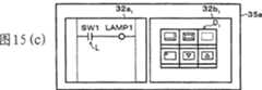
图15(a)到图15(d)为表示图12的步骤的具体范例的说明图。15( a ) to 15( d ) are explanatory diagrams showing specific examples of the steps of FIG. 12 .
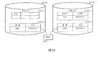
图16为表示根据图15(a)到图15(d)的步骤被执行的属性数据复制的具体形态的说明图。Fig. 16 is an explanatory diagram showing a specific form of copying of attribute data executed in accordance with the steps of Fig. 15(a) to Fig. 15(d).
图17(a)到图17(c)为表示图14的步骤的具体范例的说明图。17( a ) to 17( c ) are explanatory diagrams showing specific examples of the steps of FIG. 14 .
图18为表示根据图17(a)到图17(c)的步骤所执行的属性数据复制的具体形态的说明图。Fig. 18 is an explanatory diagram showing a specific form of attribute data copying executed in accordance with the steps of Fig. 17(a) to Fig. 17(c).
图19(a)为表示用CAD软件的数据用阶梯编辑器自动生成阶梯记号的范列的说明图。Fig. 19(a) is an explanatory diagram showing a sequence of automatically generating a ladder symbol using a data ladder editor of CAD software.
图19(b)为表示用CAD软件的数据用画面作成编辑器自动生成图标的范例的说明图。Fig. 19(b) is an explanatory diagram showing an example of automatically generating an icon using a data screen creation editor of CAD software.
图20为表示保存上述CAD软件的数据的CAD数据库的构成的说明图。FIG. 20 is an explanatory diagram showing the structure of a CAD database storing data of the CAD software.
图21(a)为表示经由开放网络与其它系统连接的第一至第三显示/控制系统的方框图。Fig. 21(a) is a block diagram showing first to third display/control systems connected with other systems via an open network.
图21(b)为表示与开放网络连接的计算机装置中,用不同系统的数据库自动生成阶梯记号及图标的范例的说明。FIG. 21( b ) is an illustration showing an example of automatically generating ladder symbols and icons using databases of different systems in a computer device connected to an open network.
图22为表示本发明的第二实施方式的第一显示/控制系统的构成的方框图。Fig. 22 is a block diagram showing the configuration of the first display/control system according to the second embodiment of the present invention.
图23为表示本发明的第二实施方式的第一至第三显示/控制系统中的计算机装置的项目文件中所形成的数据库的形态的说明图。23 is an explanatory diagram showing the form of a database formed in the project file of the computer device in the first to third display/control systems according to the second embodiment of the present invention.
图24为表示上述计算机装置的项目文件中所形成的其它的数据库的形态的说明图。Fig. 24 is an explanatory diagram showing the form of another database formed in the project file of the computer device.
图25为表示上述计算机装置的项目文件中所形成的另外的数据库的形态的说明图。Fig. 25 is an explanatory diagram showing the form of another database formed in the project file of the computer device.
图26为表示本发明的第二实施方式的第二显示/控制系统的构成的方框图。Fig. 26 is a block diagram showing the configuration of a second display/control system according to the second embodiment of the present invention.
图27为表示本发明的第二实施方式的第三显示/控制系统的构成的方框图。Fig. 27 is a block diagram showing the configuration of a third display/control system according to the second embodiment of the present invention.
图28为表示上述第一至第三显示/控制系统的计算机装置所执行的编辑器处理中,先被执行的程序设计程序的步骤的流程图。Fig. 28 is a flowchart showing the steps of a programming program executed first among the editor processes executed by the computer devices of the first to third display/control systems.
图29为表示图28的程序设计处理后被执行的画面作成处理的步骤的流程图。FIG. 29 is a flowchart showing the procedure of screen creation processing executed after the programming processing of FIG. 28 .
图30为表示上述编辑器处理中,先执行的画面作成处理的步骤的流程图。FIG. 30 is a flowchart showing the procedure of screen creation processing executed first in the above-mentioned editor processing.
图31为表示图30的画面作成处理后所执行的程序设计的步骤的流程图。FIG. 31 is a flowchart showing the procedure of programming executed after the screen creation process in FIG. 30 .
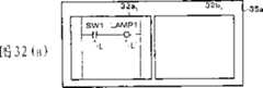
图32(a)至图32(d)为表示图29的步骤的具体范例的说明图。32( a ) to 32( d ) are explanatory diagrams showing specific examples of the steps of FIG. 29 .
图33为表示根据图32(a)至图32(d)的步骤所执行的处理的具体形态的说明图。Fig. 33 is an explanatory diagram showing a specific form of processing executed in accordance with the steps in Fig. 32(a) to Fig. 32(d).
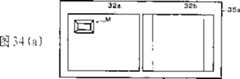
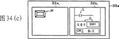
图34(a)至图34(c)为表示图31的步骤的具体范例的说明图。34( a ) to 34( c ) are explanatory diagrams showing specific examples of the steps of FIG. 31 .
图35为表示根据图34(a)至图34(c)的步骤所执行处理的具体形态的说明图。Fig. 35 is an explanatory diagram showing a specific form of processing executed in accordance with the steps in Fig. 34(a) to Fig. 34(c).
图36为表示由复制和粘贴所复制的属性数据及其所伴随的阶梯记号或图标的显示范例的说明图。Fig. 36 is an explanatory diagram showing a display example of attribute data copied by copy and paste and its accompanying ladder marks or icons.
图37为表示本发明的第三实施方式的第一显示/控制系统的构成的方框图。Fig. 37 is a block diagram showing the configuration of the first display/control system according to the third embodiment of the present invention.
图38(a)为表示用于复制上述第三实施方式的第一至第三显示/控制系统中的计算机装置上所执行的属性数据的数据结构的说明图。Fig. 38(a) is an explanatory diagram showing a data structure for copying attribute data executed on computer devices in the first to third display/control systems of the above-mentioned third embodiment.
图38(b)为表示上述数据结构中的项目文件的说明图。Fig. 38(b) is an explanatory diagram showing a project file in the above data structure.
图38(c)为表示上述数据结构中的地址信息的说明图。Fig. 38(c) is an explanatory diagram showing address information in the above data structure.
39(a)及图39(b)为表示包含于上述各个计算机装置的数据文件中的阶梯文件的说明图。39(a) and FIG. 39(b) are explanatory diagrams showing a ladder file included in the data file of each of the above-mentioned computer devices.
图40(a)为表示上述计算机装置中所形成的画面文件的说明图。Fig. 40(a) is an explanatory diagram showing a screen file created in the computer device.
图40(b)为详细表示上述画面文件中的部分数据的说明图。Fig. 40(b) is an explanatory diagram showing the details of partial data in the above screen file.
图41为表示包含于上述数据文件中的共通数据库的说明图。Fig. 41 is an explanatory diagram showing a common database included in the above data file.
图42为表示上述计算机装置中,将用户程序及用户画面合并存储的数据文件的说明图。Fig. 42 is an explanatory diagram showing a data file in which a user program and a user screen are collectively stored in the computer device.
图43为表示本发明的第三实施方式的第二显示/控制系统的构成的方框图。Fig. 43 is a block diagram showing the configuration of a second display/control system according to the third embodiment of the present invention.
图44为表示本发明的第三实施方式的第三显示/控制系统的构成的方框图。Fig. 44 is a block diagram showing the configuration of a third display/control system according to the third embodiment of the present invention.
图45为表示在上述第一至第三显示/控制系统中用计算机装置所执行的编辑器处理中,先执行程序设计处理后再执行画面作成处理的步骤的流程图。Fig. 45 is a flow chart showing the steps of executing the program design process and then the screen creation process in the editor process executed by the computer device in the first to third display/control systems.
图46为表示在上述编辑器处理中先执行画面作成处理后执行程序设计处理的步骤的流程图。Fig. 46 is a flowchart showing the procedure for executing the screen creation process and then the programming process in the above-mentioned editor process.
图47(a)至图47(d)为表示图45的步骤的具体范例的说明图。47( a ) to 47( d ) are explanatory diagrams showing specific examples of the steps of FIG. 45 .
图48为表示根据图47(a)至图47(d)的步骤所执行的处理的具体形态说明图。FIG. 48 is an explanatory diagram showing a specific form of processing executed in accordance with the steps of FIG. 47( a ) to FIG. 47( d ).
图49(a)至图49(c)为表示图46的步骤的具体范例的说明图。49( a ) to 49( c ) are explanatory diagrams showing specific examples of the steps of FIG. 46 .
图50为表示根据图49(a)至图49(c)的步骤所执行处理的具体形态的说明图。Fig. 50 is an explanatory diagram showing a specific form of processing executed in accordance with the steps of Fig. 49(a) to Fig. 49(c).
图51为表示本发明的第4实施方式的第一显示/控制系统的构成的方框图。Fig. 51 is a block diagram showing the configuration of a first display/control system according to a fourth embodiment of the present invention.
图52(a)为表示使变量具有功能属性的第二装置的具体范例的说明图。Fig. 52(a) is an explanatory diagram showing a specific example of the second means for assigning functional attributes to variables.
图52(b)为表示用于设定上述功能属性的对话框(dialog box)的说明图。FIG. 52(b) is an explanatory diagram showing a dialog box (dialog box) for setting the above-mentioned function attributes.
图53为表示显示上述变量的变量列表的说明图。Fig. 53 is an explanatory diagram showing a variable list displaying the above variables.
图54为表示第4实施方式的各个显示/控制系统中,由设置于计算机装置中的数据文件所形成的阶梯文件的构成的说明图。54 is an explanatory diagram showing the structure of a ladder file formed from data files installed in a computer device in each display/control system of the fourth embodiment.
图55为表示在上述的各个显示/控制系统中,由设置于计算机装置中的数据文件所形成的画面文件的构成的说明图。Fig. 55 is an explanatory diagram showing the structure of a screen file formed from a data file provided in a computer device in each of the display/control systems described above.
图56为表示在上述的各个显示/控制系统中,设置于计算机装置中的数据文件的其它的构成的说明图。Fig. 56 is an explanatory diagram showing another structure of a data file provided in a computer device in each of the above-mentioned display/control systems.
图57为表示本发明的第4实施方式的第二显示/控制系统的构成的方框图。Fig. 57 is a block diagram showing the configuration of a second display/control system according to the fourth embodiment of the present invention.
图58为表示本发明的第4实施方式的第三显示/控制系统的构成的方框图。Fig. 58 is a block diagram showing the configuration of a third display/control system according to the fourth embodiment of the present invention.
图59为表示作成上述的各个显示/控制系统中被执行的用户程序的步骤的流程图。Fig. 59 is a flowchart showing the steps of creating a user program to be executed in each of the above-mentioned display/control systems.
图60为表示作成上述的各个显示/控制系统中被执行的用户画面的步骤的流程图。Fig. 60 is a flow chart showing the steps of creating a user screen executed in each of the display/control systems described above.
图61(a)至图61(c)为表示将用户程序及用户画面同时进行作成时的阶梯编辑器及画面作成编辑器的动作的具体范例的说明图。61(a) to 61(c) are explanatory diagrams showing specific examples of the operations of the ladder editor and the screen creation editor when simultaneously creating the user program and the user screen.
图62为表示本发明的第5实施方式的第一显示/控制系统的构成的方框图。Fig. 62 is a block diagram showing the configuration of a first display/control system according to a fifth embodiment of the present invention.
图63(a)及图63(b)为表示第5实施方式的各个显示/控制系统中,在设置于计算机装置中的画面作成编辑器上被输入的复合组件的数据和存储根据这个数据用阶梯编辑器所生成的阶梯电路的子文件(sub file)之间的建立关联的说明图。Fig. 63(a) and Fig. 63(b) show the data of the composite component input on the screen creation editor provided in the computer device and the data stored according to this data in each display/control system of the fifth embodiment. An explanatory diagram of establishing associations between sub-files of the ladder circuit generated by the ladder editor.
图64为表示本发明的第5实施方式的第二显示/控制系统的构成的方框图。Fig. 64 is a block diagram showing the configuration of a second display/control system according to the fifth embodiment of the present invention.
图65为表示本发明的第5的实施方式的第三显示/控制系统的构成的方框图。Fig. 65 is a block diagram showing the configuration of a third display/control system according to the fifth embodiment of the present invention.
图66为表示上述的各个显示/控制系统中所被执行的、伴随着将复合组件配置在用户画面中生成阶梯电路的处理步骤的流程图。Fig. 66 is a flowchart showing the steps of processing executed in each of the above-mentioned display/control systems to generate a ladder circuit by arranging composite components on the user screen.
图67(a)至图67(c)为表示配置复合开关的复合组件时,图66的处理步骤的具体范例的说明图。FIGS. 67( a ) to 67 ( c ) are explanatory diagrams showing specific examples of the processing steps of FIG. 66 when a composite module of a composite switch is arranged.
图68为表示从上述复合开关的复合组件生成阶梯电路时所利用的阶梯列表的说明图。Fig. 68 is an explanatory diagram showing a ladder list used when generating a ladder circuit from the composite modules of the composite switch.
图69(a)为表示配置在画面作成窗口上的计数器的复合组件的说明图。Fig. 69(a) is an explanatory diagram showing a composite component of a counter arranged on a screen creation window.
图69(b)为表示通过配置计数器的复合组件,在阶梯窗口上所生成的阶梯电路的电路图。Fig. 69(b) is a circuit diagram showing a ladder circuit generated on a ladder window by disposing composite components of counters.
图70为表示从上述计数器的复合组件生成阶梯电路时所利用的阶梯列表的说明图。Fig. 70 is an explanatory diagram showing a ladder list used when generating a ladder circuit from the above-mentioned composite module of the counter.
图71(a)为表示将对应上述复合开关的阶梯电路作为子程序,从主程序跳转到其子程序的阶梯电路的电路图。Fig. 71(a) is a circuit diagram showing a ladder circuit that jumps from the main program to its subroutine, using the ladder circuit corresponding to the composite switch as a subroutine.
图71(b)为表示将对应上述计数器的阶梯电路作为子程序,从主程序跳转到其子程序的阶梯电路的电路图。Fig. 71(b) is a circuit diagram showing a ladder circuit that jumps from the main program to its subroutine, using the ladder circuit corresponding to the above-mentioned counter as a subroutine.
图72为表示本发明的第6实施方式的第一显示/控制系统的构成的方框图。Fig. 72 is a block diagram showing the configuration of the first display/control system according to the sixth embodiment of the present invention.
图73为表示第6的实施方式的各个显示/控制系统的计算机装置中的阶梯解析部作为数据持有的、数据阶梯指令和组件间建立对应的说明图。FIG. 73 is an explanatory diagram showing correspondence between data ladder commands and components held by the ladder analyzing unit in the computer device of each display/control system according to the sixth embodiment as data.
图74(a)及图74(b)为用于表示阶梯指令和关键字之间建立关联的范例的阶梯电路图。FIG. 74( a ) and FIG. 74( b ) are ladder circuit diagrams showing examples of establishing associations between ladder instructions and keywords.
图75(a)及图75(b)为表示上述显示/控制系统中被设置于计算机装置中的组件文件的构成的说明图。75(a) and 75(b) are explanatory diagrams showing the structure of a component file provided in the computer device in the display/control system.
图76为表示本发明的第6实施方式的第二显示/控制系统的构成的方框图。Fig. 76 is a block diagram showing the configuration of a second display/control system according to the sixth embodiment of the present invention.
图77为表示本发明的第6实施方式的第三显示/控制系统的构成的方框图。Fig. 77 is a block diagram showing the configuration of a third display/control system according to the sixth embodiment of the present invention.
图78为表示上述的各个显示/控制系统中被执行的、将经由从阶梯程序的生成至组件数据库的作成、到用户画面的作成的处理步骤的流程图。Fig. 78 is a flow chart showing the steps of processing executed in each of the display/control systems described above, from creation of a ladder program, creation of a component database, and creation of a user screen.
图79为表示图78的处理中的组件数据库的作成步骤的流程图。Fig. 79 is a flowchart showing the procedure for creating a component database in the processing of Fig. 78 .
图80为表示使编辑部的各个部和数据文件的各个部之间的关联,与图78的处理对应的方框图。Fig. 80 is a block diagram showing the correspondence between each section of the editing section and each section of the data file, corresponding to the processing of Fig. 78 .
图81(a)为表示阶梯窗口上生成的阶梯程序的说明图。Fig. 81(a) is an explanatory diagram showing a ladder program generated on a ladder window.
图81(b)至图81(e)为表示用图79的处理步骤所得到的组件数据库来作成用户画面的过程的说明图。81(b) to 81(e) are explanatory diagrams showing the procedure of creating a user screen using the component database obtained in the processing procedure of FIG. 79. FIG.
图82为表示根据用页面模式生成的阶梯程序,作成组件数据库的步骤的流程图。Fig. 82 is a flow chart showing the steps of creating a component database based on the ladder program created using the page pattern.
图83(a)为表示用页面模式所作成2页阶梯程序的说明图。Fig. 83(a) is an explanatory diagram showing a two-page ladder program created in the page mode.
图83(b)为表示对应图83(a)的阶梯程序的2页用户画面的说明图。Fig. 83(b) is an explanatory diagram showing a two-page user screen corresponding to the ladder program in Fig. 83(a).
图84(a)为表示通过现有的阶梯编辑器,赋予附带信息的阶梯图的说明图。Fig. 84(a) is an explanatory diagram showing a ladder diagram to which incidental information is given by a conventional ladder editor.
图84(b)为表示通过现有的画面作成编辑器,赋予附带信息的画面的说明图。Fig. 84(b) is an explanatory diagram showing a screen to which supplementary information is given by a conventional screen creation editor.
具体实施方式Detailed ways
下面,通过实施方式来进一步详细地说明本发明,但并不由此来限定本发明。Hereinafter, the present invention will be described in further detail through embodiments, but the present invention is not limited thereto.
【实施方式1】【Embodiment 1】
关于本发明的一个实施方式,根据图1至图21进行说明,其内容如下:About an embodiment of the present invention, illustrate according to Fig. 1 to Fig. 21, its content is as follows:
本实施方式的显示/控制系统,有各式各样的构成方式可以考虑,在此,针对第一至第三的构成进行说明。Various configurations are conceivable for the display/control system of this embodiment, and here, the first to third configurations will be described.
首先,图1所示,第一显示/控制系统包含可编程显示器1及PLC2。First, as shown in FIG. 1 , the first display/control system includes a
作为显示功能部的可编程显示器1具有:CPU(中央处理器)11、内存部12、VRAM(视频随机存储器)13、显示器14、图形控制器(graphics controller)15、触摸板16(touch panel)、触摸板控制器17(touch panel controller)、维修端口18(maintenance port)及通信控制器19。The
内存部12包含DRAM 12a(动态随机存储器)、FEPROM(flash Erasable andProgrammable快闪式可抹除可编程只读存储器)12b等内存。DRAM 12a(动态随机存取内存)主要用于显示控制等的演算处理时的工作,此外,可用于和PLC2之间进行数据交换时的数据暂存区。FEPROM12b为可将内容重写的只读存储器,实现一般个人计算机中的硬盘驱动器(Hard Disk Drive)的任务。闪存(FlashMemory)没有可动部分,耐冲击,因此在恶劣的周围环境下也可稳定地动作。The
另外,上述的FEPROM12b如图2所示,具有分别存储显示控制系统程序、通信协议和用户画面(画面数据)的区域。显示控制系统程序是用来实现进行画面显示控制的基本功能的程序。通信协议是与PLC2间的通信处理所用的协议,根据PLC2的种类(制造商)固定下来。用户画面由后述的画面作成编辑器32b作成,并下载至FEPROM12b。这个用户画面包含作为应显示在显示器14的基本画面和图像块(显示符号)的图标的数据及赋予各个图标的后述处理指示语W(参照图3)等,构成显示内容程序。In addition, as shown in FIG. 2, the above-mentioned
上述的图标作为触发开关、灯、各种显示器等图像化的基本组件预先准备。另外,作为图标还包含动画功能部(即标签),该动画功能部为了在画面的任意位置上动态地表现开关和数值显示器等,在希望的位置设定的矩形区域中设定所想要的动画功能。The above-mentioned icons are prepared in advance as basic components for visualizing trigger switches, lamps, various displays, and the like. In addition, as an icon, an animation function part (that is, a label) is also included. In order to dynamically express a switch and a numerical display at an arbitrary position on the screen, the animation function part sets a desired position in a rectangular area set at a desired position. Animation function.
如图3所示,包含于画面数据中的处理指示语W,按基本画面上每个应被执行的事件作成。这个处理指示语W基本来说,具有将应该执行显示控制动作的基本画面的文件编号F、指定在应在这个基本画面上执行的动作内容的事件名称T和执行每个事件所参照的一个或多个数据构成的参照信息I作为一组的数据。As shown in FIG. 3, the processing instruction W included in the screen data is created for each event to be executed on the basic screen. This processing directive W basically has the file number F of the basic screen on which the display control action should be executed, the event name T specifying the content of the action to be executed on this basic screen, and an or The reference information I composed of a plurality of data is regarded as one set of data.
CPU11根据存储在前述FEPROM12b中的显示控制系统程序来控制可编程显示器1的各个部分的动作。另外,CPU11具有控制经由后述的维修端口18与后述的计算机装置3进行通信的功能。从画面作成编辑器32b接收到画面数据后将其存储在FEPROM12b中,或将从阶梯编辑器32a接收到作为控制步骤程序的阶梯程序(用户程序)后将其传送至PLC2。CPU11 controls the operation|movement of each part of the
VRAM 13是将显示在显示器14的画面的图像暂时保持的内存,将来自FEPROM12b的画面数据的图像,按照在水平方向显示的顺序将其作为像素数据存储。The
显示器14由液晶板和EL(边缘发光板Edge-lighted panel)等的平板型显示组件构成。图形控制器15是将展开于VRAM13的画面图像绘制于显示器14的驱动软件。触摸板16是为了在显示器14的显示画面上进行输入工作而设置的,模拟阻抗膜式的触摸板较合适。触摸板控制器17是将触摸板16的输出电压变换为输入位置信息并输出至CPU11。The
维修端口18是用于和后述计算机装置3进行通信的通信端口。另一方面,通信控制器19是通过通信电缆(如RS-232C)控制在PLC2之间传送的有关控制和监视输入输出机器4的数据等和读取PLC2的输出数据的接口。The
作为控制功能部的PLC2,通过内置CPU部,根据后述的控制功能程序,以阶梯编辑器32a生成的用户程序(阶梯程序)所确定的步骤,控制输入输出机器4的动作。The
PLC2内的内存中,设定为通过指定地址,字符装置(word device)及位装置(bit device)可指定存储位置。字符装置将输入输出数据设定为如数值的文本数据,位装置设定为如开、关的状态的位数据。通过此设定,只要访问PLC2内的任何字符装置或位装置就可控制输出入机器4,或将与其动作状态相关的信息分别取出。In the internal memory of PLC2, the storage location can be specified by specifying the address, word device and bit device. The character device sets input and output data as text data such as numerical values, and the bit device sets bit data such as on and off states. Through this setting, as long as any character device or bit device in the PLC2 is accessed, the I/
可编程显示器1,一方面将上述的位装置或字符装置所示的状态信息中必要的信息适时地读取至内存部12。另一方面,重复读出上述的处理指示语W,一面参照PLC2方的状态信息一面执行用各个处理指示语W的事件名称T指定的内容的动作。这样,可执行随位装置或字符装置的状态变化而变化的显示动作。The
可编程显示器1的显示动作按照图4所示的流程图的步骤进行。The display operation of the
首先,先选择可与控制输入输出机器4的PLC2通信的联机模式,或只让可编程显示器1动作的脱机模式(S1)。选择脱机模式时(NO),在可编程显示器1中进行设定处理、诊断处理等各种处理(S6),接着将处理返回至S1。First, select the online mode which can communicate with PLC2 which controls the input/
在S1中选择联机模式时(YES),作为起动处理,设定于可编程显示器1的内存部12的前述处理指示语W中所引用的PLC2方的状态信息,被取出到可编程显示器1。具体来说,可从存储在内存部12的处理指示语W中、从与现在显示的基本画面有关的处理指示语W所包含的信息中,抽出设定PLC2中的字符装置及位装置的地址。接着,通过根据该地址直接访问PLC2的内存,将被指定地址的状态信息展开到内存部12中,并显示在操作面板画面上。在联机模式下,判断是否有由显示在可编程显示器1上的操作面板画面进行的输入操作(S2)。在此,如有输入操作时,根据所输入的数据执行规定的演算处理(S3),并进行数据通信处理(S4)。When the online mode is selected in S1 (YES), the status information of the PLC2 side referred to in the aforementioned process instruction W set in the
随后,执行各个事件的显示处理(S5)。这时,根据存储在内存部12的处理指示语W的中的、由通信处理抽出的状态信息进行显示动作。Subsequently, display processing of each event is performed (S5). At this time, the display operation is performed based on the status information extracted by the communication processing stored in the processing instruction W of the
接着,针对计算机装置3进行说明。Next, the
如图1所示,计算机装置3由个人计算机等通用计算机构成。该计算机装置3具有CPU31、编辑部32、数据文件33、内存部34、显示器35、输入装置36、外部存储装置37及接口部(图中、I/F)38。As shown in FIG. 1 , the
CPU31在安装在计算机装置3的OS(操作系统)上,使包含编辑部32的各种的应用程序软件进行动作时,对各部进行控制和演算处理。When the
内存部34具有RAM、ROM等内存,实现固定数据的存储、暂时数据的存储,提供CPU31在演算处理时的工作区域等任务。The
编辑部32包含阶梯编辑器32a、画面作成编辑器32b、应用程序32c及复制功能部32d。The
作为第二编辑装置的阶梯编辑器32a,是用于作成确定PLC2控制步骤以使输入输出机器4按照所希望的顺序进行动作的程序设计软件,其构成为能够在显示器35的显示画面35a(参照图15(a))上,配置对应输入输出机器4的动作的阶梯记号(符号及控制符号)并作成阶梯图。在该阶梯编辑器32a中,例如,可用前述符合国际标准IEC(国际电气技术标准会议)的程序设计语言。The
另外,阶梯编辑32a,通过表示输入输出机器4的名称(设备名)等的变量,分配输入输出编号(I/O分配)来建立分别赋予PLC2的输入端子及输出端子的输入编号和输出编号与连接到各个输入输出端子的输入输出机器4之间的对应关系。将此分配的结果,存储在后述的阶梯文件33a中。In addition, the
进行上述分配时,内存部34中,分别将输入编号和输出编号作为地址,存储对应各地址的设备名称。从前,这样的分配,根据PLC制造商的不同也就不同,由于用绝对地址设定,因此就必须准备对应制造商的内存列表(MemoryTable)。但是以IEC为标准的本阶梯编辑器32a,通过上述的变量(自由变量),用户可确定输入输出,因此不需要上述的内存列表。另外,一次确定分配后,以后还可以变更。When the above allocation is performed, the
用阶梯编辑器32a生成的用户程序,经由可编程显示器1(或直接)传送至PLC2,并下载至PLC的内存中。The user program generated by the
作为第一编辑装置的画面作成编辑器32b,使可编程显示器1具有在用于管理输入输出机器4的运行状况和工作指示等的各种监视器、在机器上输入设定值和工作指示等的作为终端的功能,是作成在显示器14显示的画面的画面作成软件。一般来说,画面作成编辑器32b具有开关、灯、数值键、各种显示器(如数值显示器、仪表显示器及图表显示器)等的组件(图标),绘制功能、文本输入功能等,以便可以作成用户独有的画面(用户画面)。作为组件,并不是只有单一功能的单一组件,而是准备具有多个的功能的、复合开关、计数器、定时器等的复合组件。这样的复合组件,和单一组件相同,以库方式进行登录以使通过进行拖曳和拖放等的操作,可配置在基本画面上所希望的位置。另外,画面作成编辑器32b经由前述的变量,对配置在作成的画面中的图标的各个输入输出机器4,分配前述的输入输出编号(地址)。As the
通过上述的画面作成编辑器32b作成的用户画面,存储在后述的画面文件33b中,根据需要,经由接口部38传送至可编程显示器1,并将其作为画面文件下载至FEPROM12b中。The user screen created by the above-mentioned
应用程序32c,主要是通用的应用程序软件,由生成可使阶梯编辑器32a与画面作成编辑器32b进行交换的属性数据的软件构成。作为该软件,可以列举出作成数据的表格计算软件和设计电路等CAD软件等。The
作为数据复制装置的复制功能部32d,利用OS的数据复制功能,在用画面作成编辑器32b作成的画面上,自动生成(绘制)对应用阶梯编辑器32a作成的阶梯图中的阶梯记号的图标,同时将该阶梯记号的属性数据作为图标的属性数据进行复制。另外,复制功能部32d也同样利用OS的数据复制功能,在用阶梯编辑器32a作成的阶梯图中,自动生成(绘制)对应用画面作成编辑器32b作成的画面中的阶梯记号的图标,同时将该图标的属性数据作为阶梯记号的属性数据进行复制。The
具体来说,属性数据的复制可利用经由设置于内存部34的后述的剪贴板CB(参照图16及图18),进行拖曳&拖放或复制&粘贴的功能来进行。Specifically, copying of the attribute data can be performed using a function of drag&drop or copy&paste via a clipboard CB (see FIG. 16 and FIG. 18 ), which will be described later, provided in the
存储在剪贴板CB中的数据结构,如图5(a)所示,由头码(header code)、内存大小、对象类型、预留、地址信息数量、地址信息(1~N)及预留构成。其中,内存大小是将数据存储在剪贴板CB中时所需要的内存容量。对象类型是剪贴板CB中存储的组件的预先设定的种类。这个对象类型,如图5(b)所示,设定有位开关、触发开关、灯、数值显示器、柱图、饼图、半圆图、圆柱图、计量图及设定值显示器。地址信息,如图5(c)所示,由地址(地址名称)、预留、地址附带信息、预留、对象类型及预留构成。地址附带信息是关于符号的种类(整数符号、描述符号)的信息。地址信息中的对象类型与上述的对象类型的内容相同,并指定地址对应哪个组件,为此只打开(ON)必要的组件的位。The data structure stored in the clipboard CB, as shown in Figure 5(a), consists of header code, memory size, object type, reservation, number of address information, address information (1~N) and reservation . Wherein, the memory size is the memory capacity required for storing data in the clipboard CB. Object types are preset types of components stored in the clipboard CB. This object type, as shown in Figure 5(b), is configured with bit switches, trigger switches, lamps, numerical displays, column graphs, pie charts, semicircle graphs, cylinder graphs, meter graphs, and set value displays. Address information, as shown in FIG. 5(c), is composed of address (address name), reservation, address incidental information, reservation, object type, and reservation. The address incidental information is information on the type of symbol (integer symbol, descriptor symbol). The object type in the address information has the same content as the above-mentioned object type, and which component the address corresponds to is specified, and only the bits of the necessary components are turned on (ON) for this purpose.
并且,上述的复制功能部32d也可作为阶梯编辑器32a或画面作成编辑器32b的任何一方的一个功能分别包含于阶梯编辑器32a或画面作成编辑器32b中。Furthermore, the above-mentioned
计算机装置3,通过具有编辑部32,起到用于进行用户程序及用户画面的作成及编辑的编辑装置的功能。另外,编辑部32在后述的各个实施方式中虽有部分不同的功能,但为了方便,对于各个实施方式中相同的符号进行附注说明。The
可将编辑部32作为软件包(package software)或特别订做软件(order madesoftware),采用程序媒介(media)的形态提供给用户的软件,举例来说,可存储在可与计算机装置3分离的存储介质5中。接着,编辑部32从存储介质5安装至计算机装置3中,可发挥编辑功能。后述的各个实施方式中的编辑部32也是相同构成的软件。The
并且,编辑部32也可以存储在单一的存储介质5当中,但阶梯编辑器32a和画面作成编辑器32b也可以存储在分别的存储介质当中。Furthermore, the
上述的程序媒介,适用如磁带和卡带等的带式,软盘和硬盘等的磁盘式,CD-ROM、MO、MD、(DVD)等的光盘式,IC卡(包含内存卡(Memory Card))、光学卡等的卡片式媒介。另外,上述的程序媒介也可以是承载包含MASKROM、EPROM、FEPROM、FLASHROM等半导体内存的固定程序的媒介。The above-mentioned program medium is suitable for tape types such as tapes and cassettes, disk types such as floppy disks and hard disks, optical disk types such as CD-ROM, MO, MD, (DVD), and IC cards (including memory cards). , optical cards and other card media. In addition, the program medium described above may be a medium carrying a fixed program including a semiconductor memory such as MASKROM, EPROM, FEPROM, or FLASHROM.
另外,计算机装置3,由于可连接包含因特网等通信网路,也可以是承载由通信网络下载的流动的程序的存储介质。但是,如从通信网络下载程序时,该进行下载的软件须预先存储在计算机装置3中,或从别的存储介质安装。In addition, since the
数据文件33包含阶梯数据33a、画面文件33b及应用程序文件33c。The data file 33 includes
作为控制步骤程序文件的阶梯文件33a,如图6所示,由命令文件部33a1及属性数据文件部33a2构成。命令文件部33a1存储对应被输入的阶梯记号的助记符(阶梯指令)及运算值。属性数据文件部33a2与命令文件部33a1对应,存储关于被输入的阶梯指令的设备名称及地址。The
作为显示内容程序文件的画面文件33b,如图6所示,由图形数据文件部33b1及属性数据文件部33b2构成。图形数据文件部33b1存储关于所输入的图标的图形数据,属性数据文件部33b2与图形数据文件部33b1对应,存储关于所输入的图标的设备名称及地址。The
阶梯文件33a及画面文件33b是通过属性数据文件部33a2、33b2而建立关联关系,因此第一至第三显示/控制系统中的显示动作及控制动作相互关联。The
应用程序文件33c是将用应用程序32c作成的数据和上述的属性数据文件部33a2、33b2的属性数据建立关联关系的属性数据进行存储。The
显示器35,虽是由CRT、LCD等构成,但在面板式计算机的计算机装置3中由液晶面板和EL板等的平板型显示元件构成。输入装置36是用于进行输入操作的键盘、鼠标等装置,特别是对于在GUI(图形用户界面)的环境上进行操作的编辑部32的输入工作来说,鼠标等装置是较合适的。外部存储装置37是硬盘装置等磁盘驱动器、CD-ROM驱动器等光盘驱动器等装置,最少也必须是可读出存储在前述存储介质5中的程序等信息的装置。接口部38是与可编程显示器1之间进行数据通信的输入输出部。用阶梯编辑器32a生成的用户程序及画面作成编辑器32b作成的用户画面,经由该接口部38传送至可编程显示器1。The
继续针对第二显示/控制系统进行说明。Continue to describe the second display/control system.
图7所示的第二显示/控制系统与前述的第一显示/控制系统相同,虽包含可编程显示器1及PLC2,但是这里的可编程显示1为具有PLC的功能,其构成是可直接控制输入输出机器4。这样,可编程显示器1在内存部12具有SRAM12c的同时,除了前述的通信控制器19还具有输入输出装置(图中、I/O单元)20及输入/输出(I/O)控制接口21。The second display/control system shown in Figure 7 is the same as the aforementioned first display/control system. Although it includes
SRAM12c为具有存储由阶梯编辑器32a生成的用户程序的存储区域,及存储由阶梯编辑器32a输入的变量的存储区域。另外。FEPROM12b为了具有PLC的功能,如图8所示,除了分别存储显示控制系统程序和通信协议和画面数据等的存储区域,也具有分别存储控制功能程序和用户程序分别的存储区域。控制功能程序为实现顺序控制的基本功能的程序。The
输入输出单元20是为了让输入输出机器4可连接,具有多个输入输出端子及输入输出电路等。输入/输出(I/O)控制接口21为协调CPU11和输入输出单元20间的信号收发的接口电路,具有输入输出内存、D/A变换器、A/D变换器等。The input/
再继续针对第三显示/控制系统进行说明。Continue to describe the third display/control system.
图9所示的第三显示/控制系统是用软件来进行动作,也就是以开放式控制器(软件PLC)作为中心构成的。The third display/control system shown in FIG. 9 is operated by software, that is, it is constituted centering on an open controller (software PLC).
开放式控制器,由计算机装置3构成,为了连接输入输出机器4,代替前述的第一显示/控制系统中的计算机装置3的接口部38,具有输入输出单元(图中、I/O单元)39及输入/输出(I/O)控制接口40。The open controller is composed of a
输入输出单元39为了与输入输出机器4连接,具有多个输入输出端子及输入输出电路等。这样的输入输出单元39通常采用I/O板方式安装于计算机装置3中,但是也可以采用遥控I/O方式独立安装于计算机装置3的外部。The input/
输入/输出(I/O)控制接口40为协调CPU31和输入输出单元39间的信号收发的接口电路,且具有输入输出内存、D/A变换器、A/D变换器等。此I/O控制接口40是将输入输出于输入输出机器4间的数字信号或模拟信号与中央处理器进行交换。The input/output (I/O)
另外,计算机装置3,为具有作为开放式控制器的功能,具有接口单元(图中、I/F单元)41。接口单元41是对应使用以太网络(注册商标)等通用通信协议的开放式网络8的输入输出部,且与开放式网络8连接。这样,计算机装置3可经由开放式网络8与其它的计算机装置、可编程显示器、PLC等连接。In addition, the
内存部34和前述FEPROM12b相同,如图8所示,具有分别存储显示控制系统程序、通信协议、用户画面、控制功能程序和用户程序的存储区域。The
这样构成的计算机装置3在配备有输入输出机器4的目标系统运转时(联机状态),通过将作成的画面和现场的情况显示在显示器35上,除了具有监视目标系统的运转状况的监视屏幕的功能以外,还可以控制目标系统中的输入输出机器4。这时,计算机装置3根据控制功能程序,执行用阶梯编辑器32a生成且存储在阶梯文件33a中的用户程序。另一方面,计算机装置3在目标系统非运转状态时(脱机状态),具有通过起动阶梯编辑器32a或画面作成编辑器32b生成用户程序或用户画面的编辑装置的功能。The
在此,对于第一至第三显示/控制系统中的用户程序及用户画面的作成步骤,参照图10至图14的流程图进行说明。Here, the procedure for creating a user program and a user screen in the first to third display/control systems will be described with reference to the flowcharts in FIGS. 10 to 14 .
如图10所示,根据用户的输入操作来作判断是先作成用户画面(画面作成)还是先生成用户程序(程序设计)S11)。先生成用户程序时,执行用阶梯编辑器32a所进行的程序设计处理(1)(S12),然后执行用画面作成编辑器32b所进行的画面作成处理(2)(S13)。另一方面,先作成用户画面时,执行用画面作成编辑器32b所进行的画面作成处理(1)(S14),然后执行用阶梯编辑器32a所进行的程序设计处理(2)(S15)。As shown in FIG. 10, it is determined whether to create a user screen first (screen creation) or to generate a user program first (programming) S11) based on the user's input operation. When generating a user program first, the program design process (1) (S12) by the
接着,将生成的用户程序及用户画面以可利用的形式存储在规定的存储位置(S16)。这时,第一或第二显示/控制系统,用户程序和用户画面存储在数据文件33时,分别下载至PLC2和可编程显示器1并存储在内存部12中。或第二显示/控制系统,用户程序及用户画面存储在数据文件33时,下载至可编程显示器1并存储在内存12中。第三显示/控制系统,则将用户程序及用户画面存储在数据文件33中。Next, the generated user program and user screen are stored in a predetermined storage location in a usable form (S16). At this time, when the first or second display/control system, the user program and the user screen are stored in the data file 33, they are downloaded to the
并且,上述的例子,主要是针对画面作成或是程序设计其中一方先执行后,再执行另一方的步骤进行说明,但是不限于此,也有两方同时执行的可能。此步骤及上述的步骤,对于后述的实施方式2及实施方式3也都是相同。In addition, the above-mentioned examples mainly illustrate the steps of executing one of screen creation and program design first and then executing the other, but it is not limited thereto, and it is also possible for both of them to be executed at the same time. This step and the above-mentioned steps are also the same for
先执行程序设计处理(1)时,按照图11的流程图所示的步骤。在此,在计算机装置3中,阶梯编辑器32a及画面作成编辑器32b已被起动,显示器35的显示部35a(参照图15(a))上,显示用户画面作成用的编辑器画面(第一编辑器画面)窗口(以下称为画面作成窗口)32b1及显示用户程序生成用的编辑器画面(第二编辑器画面)窗口(以下称为阶梯窗口)32a1同时被打开。然而先执行程序设计处理(1)时,至少起动阶梯编辑器32a即可。When the programming process (1) is executed first, the procedure shown in the flowchart of FIG. 11 is followed. Here, in the
首先,在阶梯窗口32a1上,通过以各个输入输出机器4为对象配置阶梯记号来记述阶梯指令(S21)。接着输入关于被记述的阶梯指令的使用名称、地址等属性数据(S22),将阶梯记号及属性数据登录在临时文件(S23)。之后,根据用户的操作判断程序设计处理是否完成(S24)。在此,未完成时将处理返回至S21,另一方面如果已完成时,将所生成的用户程序登录在阶梯文件33a中(S25)。First, on the ladder window32a1 , ladder commands are described by arranging ladder symbols for each input/output device 4 (S21). Next, attribute data such as the use name and address of the described ladder instruction are input (S22), and the ladder symbol and attribute data are registered in a temporary file (S23). After that, it is judged whether or not the programming process is completed based on the user's operation (S24). Here, if it is not completed, the process returns to S21, but if it is completed, the generated user program is registered in the
在继续执行的画面作成(2)中,按照图12的流程图所示的步骤进行。In the screen creation (2) which is continuously executed, the procedure shown in the flowchart of FIG. 12 is followed.
首先,预先将关于登录在阶梯文件33a中的阶梯记号(阶梯指令)的属性数据导入至画面文件33b(S31)。判断阶梯窗口32a1上的阶梯记号是否由鼠标等拖曳(S32),如被拖曳时,则判断被拖曳的阶梯记号是否被拖放至画面作成窗口32b1上(S33)。在此,如确认阶梯记号确实被拖放,将根据关于被拖曳的阶梯记号的属性数据中所包含的功能,显示包含具有此功能的多个图标的对话框D1(参照图15(c))(S34)。First, the attribute data about the step symbol (step instruction) registered in the
上述的步骤中,关于用阶梯编辑器32a作成的所有阶梯记号的属性数据,预先通过S31的导入步骤全部一次复制到画面文件33b。然而,也可以将关于一个阶梯记号的属性数据,在每次拖曳及拖放时逐次导入。特别是作成包含大量的阶梯记号的阶梯图时,通过将属性数据全部一次导入,可提高处理效率。另一方面,作成包含少量的阶梯记号的阶梯图时,即使将属性数据逐次导入,也基本不会降低作成效率。因此,最好根据阶梯图的大小和其它因素选择采用哪一种导入方式。In the above-mentioned steps, the attribute data of all the ladder symbols created by the
之后,从显示在对话框D1中的多个图标中选择一个图标后,该图标被登录在临时文件(S35)中。接着,根据用户的操作判断是否结束画面作成处理(S36)。在此,如不结束时将处理返回S31,如结束时,将作成的用户画面登录在画面文件33b(S37)中。After that, when one icon is selected from the plurality of icons displayed in the dialogD1 , the icon is registered in the temporary file (S35). Next, it is determined whether or not to end the screen creation process based on the user's operation (S36). Here, if it is not finished, the process returns to S31, and if it is finished, the created user screen is registered in the
在此,对用图12的流程图的步骤进行画面作成处理(2)的具体范例进行说明。Here, a specific example of performing the screen creation process (2) using the steps of the flowchart in FIG. 12 will be described.
首先,如图15(a)所示,在阶梯窗口32a1上用阶梯编辑器32a,已绘制了代表开关(输入)的阶梯记号L和代表灯(输出)的阶梯记号L’。与此同时,阶梯文件33a,如图16所示,登录有关于开关及灯的数据。具体来说,关于开关最少登录作为名称的”SW1”及作为地址的”XB0001”。另外,关于灯最少登录作为名称的”LAMP1”及作为地址的”YB0001”。First, as shown in FIG. 15(a), a ladder symbol L representing a switch (input) and a ladder symbol L' representing a lamp (output) have been drawn on the ladder window32a1 using the ladder editor 32a . At the same time, the
在这种状态下,如图15(a)所示,将画面作成窗口32b1打开。接着如图15(b)所示,将在阶梯窗口32a1中的阶梯记号L拖曳至画面作成窗口32b1后拖放时,如图15(c)所示,对话框D1将显示在画面作成窗口32b1上。In this state, as shown in FIG. 15(a), the screen creation window32b1 is opened. Then as shown in Figure 15 (b), when dragging and dropping the ladder mark L in the
如前所述,关于用阶梯编辑器32a作成的所有阶梯记号的属性数据,预先通过导入一次全部复制至画面文件33b。或,将一个关于阶梯记号的属性数据,在每次进行拖曳及拖放时逐次导入。该导入如图16所示,是通过将属性数据暂时存储在剪贴板后,再复制到画面文件33b中来实现的。As mentioned above, the attribute data of all the ladder marks created by the
从对话框D1中具有开关功能的多个种类的图标中选择一个适当的图标后,如图15(d)所表示,被选择的图标的图像M显示在画面作成窗口32b1上,同时显示包含属性数据(名称”SW1”及特性”ON”)的对话框D2。在此,如压下OK按钮时,即确认画面作成窗口32b1上的图标M及属性数据,关于开关图标M的图形数据及属性数据被建立关联关系并存储在画面文件33b的图形数据文件部33b1及属性数据文件部33b2(参照图16)。After selecting an appropriate icon from a plurality of types of icons having a switch function in dialog boxD1 , as shown in FIG. DialogD2 for property data (name "SW1" and property "ON"). Here, when the OK button is pressed, the icon M and attribute data on the screen creation window 32b1 are confirmed, and the graphic data and attribute data of the switch icon M are associated and stored in the graphic data file
因此,用户可免除在画面作成窗口32b1上绘制开关图标的工作和输入必要属性数据的工作,可相当容易地作成用户画面。Therefore, the user can save the work of drawing switch icons on the screen creation window32b1 and the work of inputting necessary attribute data, and can create a user screen quite easily.
另一方面,先执行画面作成处理(1)时,根据图13的流程图所示的步骤进行。在此,计算机装置3中,阶梯编辑器32a及画面作成编辑器32b已被起动,显示器35的显示部35a(参照图17(a))中,阶梯窗口32a1及画面作成窗口32b1同时打开。然而,先执行画面作成处理(1)时,至少起动画面作成编辑器32b即可。On the other hand, when the screen creation process (1) is executed first, it is performed according to the procedure shown in the flowchart of FIG. 13 . Here, in the
首先,在画面作成窗口32b1上,以各个输入输出机器4为对象进行图标的配置(S41)。接着,输入关于配置的图标的使用名称、地址等的属性数据(S42),将图标及属性数据登录在临时文件(S43)中。之后,根据用户的操作判断画面作成处理是否完成(S44)。在此,如未完成时,处理将返回至S41,另一方面如果已完成时,将所作成的用户画面登录在画面文件33b中(S45)。First, on the screen creation window32b1 , icons are arranged for each input/output device 4 (S41). Next, attribute data such as the use name and address of the icon to be placed are input (S42), and the icon and attribute data are registered in a temporary file (S43). After that, it is judged whether or not the screen creation process is completed based on the user's operation (S44). Here, if not completed, the process returns to S41, and on the other hand, if completed, the created user screen is registered in the
对于继续执行的程序设计作成(2),根据图14的流程图所示的步骤进行。The program creation (2) for continuous execution is performed according to the procedure shown in the flowchart of FIG. 14 .
首先,预先将关于登录在画面文件33b中的图标的属性数据导入至阶梯文件33a(S51)。判断画面作成窗口32b1上的图标是否被拖曳(S52),如被拖曳时,则判断被拖曳的图标是否被拖放至阶梯窗口32a1上(S53)。在此,确认图标被拖放时,根据关于被拖曳的图标的属性数据中所包含的功能,显示与该功能对应的阶梯记号及上述属性数据(S54)。First, the attribute data about the icons registered in the
上述的步骤中,将关于用画面作成编辑器32b配置的全部图标的属性数据,预先在S51的导入步骤中全部一次复制到阶梯文件33a。然而,针对一个图标的属性数据,也可以在每次进行拖曳及拖放时逐次导入。In the above-mentioned steps, attribute data about all the icons arranged by the
之后,将被显示的阶梯记号登录在临时文件(S55)中。接着,根据用户的操作判断是否结束程序设计处理(S56)。在此,如不结束时将处理返回S51,如结束时,将生成的用户程序登录在阶梯文件33a(S57)。After that, the displayed step symbol is registered in a temporary file (S55). Next, it is judged based on the user's operation whether to end the programming process (S56). Here, if it is not finished, the process returns to S51, and if it is finished, the generated user program is registered in the
在此,针对用图14的流程图的步骤进行程序设计处理(2)的具体范例进行说明。Here, a specific example of performing the programming process (2) using the steps of the flowchart of FIG. 14 will be described.
首先,如图17(a)所示,画面作成窗口32b1上用画面作成编辑器32b已配置且绘制了代表开关(输入)的图标M。与此同时,画面文件33b如图18所示,登录关于开关的数据。具体来说,关于开关最少登录作为名称的”SW1”及作为地址的”XB0001”。First, as shown in FIG. 17(a), an icon M representing a switch (input) is placed and drawn on the screen creation window 32b1 using the screen creation editor32b . At the same time, the
在这种状态下,如图17(a)所示,将阶梯窗口32a1打开。接着如图17(b)所示,将画面作成窗口32b1中的图标M拖曳至阶梯窗口32a1后拖放时,如图17(c)所示,阶梯记号L及对话框D3显示在画面作成窗口32b1上。In this state, as shown in FIG. 17(a), the stepped window32a1 is opened. Next, as shown in Figure 17(b), when the icon M in the screen creation window32b1 is dragged to the ladder window32a1 and then dragged and dropped, as shown in Figure 17(c), the ladder symbol L and dialog boxD3 are displayed on the screen creation window32b1 .
如前所述,关于用画面作成编辑器32b配置的所有图示的属性数据,因为通过预先导入全部一次复制至阶梯文件33a。或,针对一个图标的属性数据,将在每次进行拖曳及拖放时逐次导入。该导入如图18所示,是通过将属性数据暂时存储在剪贴板CB后,再复制到阶梯文件33a中来实现的。As mentioned above, the attribute data of all the illustrations arranged by the
接着,如图17所表示,将对应开关功能的阶梯记号L绘制于阶梯窗口32a1上,同时显示包含属性数据(名称”SW1”)的对话框D3。在此,如压下OK按钮时,即确认了阶梯窗口32a1上的阶梯记号L及属性数据,关于开关的阶梯记号L的命令及属性数据被建立其关联性并存储在阶梯文件33a的命令文件部33a1及属性数据部33a2(参照图18)。Next, as shown in FIG. 17 , a ladder mark L corresponding to the switch function is drawn on the
因此,用户可免除在阶梯窗口32a1上绘制开关的阶梯记号的工作和输入必要的属性数据的工作,可相当容易地作成用户画面。Therefore, the user can save the work of drawing the step symbol of the switch on the step window 32a1 and the work of inputting necessary attribute data, and can create a user screen quite easily.
如上所述,与本实施方式相关的第一至第三显示/控制系统的构成为,分别具有有存储用阶梯编辑器32a生成的用户程序的阶梯文件33a和存储用画面作成编辑器32b作成的用户画面的画面文件33b,并通过复制功能部32d,在将阶梯记号的属性数据复制至画面文件33b的同时,将图标的属性数据复制至阶梯文件33a中。这样,两个文件33a、33b可以持有共通的属性数据,可容易地建立两个文件33a、33b间的关联性。As described above, the configurations of the first to third display/control systems related to this embodiment include the
另外,如果用户程序和用户画面拥有独立的数据库时,各个数据库和其它的数据库之间可以进行如上所述的属性数据的复制。具体来说,将用通用的应用程序软件(表格计算软件等)的数据库、电子电路用的CAD的数据库、由用于NC控制装置的G码程序设计(加工序序设计)等软件作成的数据库的数据,通过将该软件的操作输入画面上所输入的数据作为图像块进行选择并如前所述进行拖曳和拖放(或复制和粘贴),复制到用户程序或用户画面的数据库中。In addition, if the user program and the user screen have independent databases, the above-mentioned attribute data can be copied between each database and other databases. Specifically, databases created with general-purpose application software (table calculation software, etc.), CAD databases for electronic circuits, and software such as G-code programming (processing programming) for NC control devices The data is copied to the user program or the database on the user screen by selecting the data input on the operation input screen of the software as an image block and dragging and dropping (or copying and pasting) as described above.
特别是,通过CAD软件来进行控制盘设计时,在阶梯编辑器及画面作成编辑器之间的交换数据是有效的。In particular, when designing the control panel with CAD software, it is effective to exchange data between the ladder editor and the screen creation editor.
为了开发所有的装置系统,需要机械设计图等电力系统图。另外,作成电力系统图时,必须作成电力规格说明书、控制盘图、零件列表、硬件图(电路图等)。接着,根据所作成的电力系统图来作成控制盘后,再进行设置控制盘的装置系统的电气工序。另外,在设计及制作控制盘的工序中,首先是确定规格,再根据其规格利用CAD软件等的图面作成工具,设计电气的结构并再转移到包含PLC等显示/控制系统的程序生成。这个时候,通过利用与本实施方式相关的复制功能部32d的功能,在CAD软件中所输入的数据可用于用户程序及用户画面的作成。In order to develop all device systems, electrical system diagrams such as mechanical design drawings are required. In addition, when creating a power system diagram, it is necessary to create a power specification, a control panel diagram, a parts list, and a hardware diagram (circuit diagram, etc.). Next, after creating the control panel based on the created power system diagram, the electrical process of the device system in which the control panel is installed is performed. In addition, in the process of designing and manufacturing the control panel, first determine the specifications, and then use CAD software and other drawing tools to design the electrical structure according to the specifications, and then transfer to the program generation including the display/control system such as PLC. At this time, by utilizing the function of the
具体来说,在CAD软件编入计算机装置3的应用软件32c(参照图1、图7及图9)时,起动CAD软件,如图19(a)所示,显示部35a中显示CAD窗口32c1和阶梯窗口32a1。在CAD窗口32c1上显示与PLC的输入部连接的按扭开关(用图记号名PB001表示)和与PLC的输出部连接的灯(用图记号名PL001表示)。在此状态下,只要将显示在CAD窗口32c1中的按扭开关的图记号拖曳并拖放至阶梯窗口32a1,以与图14的流程图所示的步骤大致相同的步骤,对应按扭开关的阶梯记号L1(LD命令等)将显示在阶梯窗口32a1,同样,指示灯也会作为阶梯记号L2(OUT命令)显示在阶梯窗口32a1。Specifically, when the CAD software is incorporated into the
另一方面,用CAD的数据来作成用户画面时,如图19(b)所示,CAD窗口32c1和画面作成窗口32b1显示在显示部35a。在此状态下,如将显示在CAD窗口32c1的按扭开关的图记号进行拖曳并将其拖放至画面作成窗口32b1,以如图12的流程图所示的步骤大致相同的步骤,对应按扭开关的图标M1将显示在画面窗口32b1。这时,只要在PLC输入部和输出部让按扭开关及指示灯的功能共通化,则兼备按扭开关和指示灯的图标M1将显示在画面作成窗口32b1上。On the other hand, when a user screen is created using CAD data, as shown in FIG. 19(b), a CAD window32c1 and a screen creation window32b1 are displayed on the
进行上述的处理时,导入到阶梯文件33a及画面文件33b的数据,如图20所示,存储在构建在应用程序文件33c的CAD数据库。具体来说,也就是存储图记号名、注释、PLC关联地址等。PLC关联地址是分配给连接于PLC2的按扭开关和指示灯等的机器的地址。图记号名是赋予上述用CAD软件作成的图中的按扭开关和指示灯等的记号名。该图记号名,与上述地址建立对应关系,将按扭开关和指示灯等的地址分配给阶梯记号和图标时,设定为与代替地址使用的变量相同。注释是为了表示机器的动作状态而设置的。When the above-mentioned processing is performed, the data imported into the
在上述的CAD数据库中,通过将图记号名及变量设定为相同,可以将图记号名(名称)和PLC关联地址(地址)作为属性数据(参照图6(a)及图6(b))来处理。这样,阶梯编辑器32a及画面作成编辑器32b将图记号名作为变量与阶梯记号L1、L2及图标M合并显示。另外,画面作成编辑器32b将称为「运转」的注释显示在图标M上。In the above-mentioned CAD database, by setting the drawing symbol name and the variable to be the same, the drawing symbol name (name) and the PLC related address (address) can be used as attribute data (refer to Fig. 6(a) and Fig. 6(b) ) to process. In this way, the
在此,第三显示/控制系统,如图9所示,因为具有编辑功能及PLC功能的计算机装置3与开放式网络8连接,所以计算机装置3中的数据库可在与类似这种开放式网络8连接的其它系统A~C等的数据库之间,经由网络交换关于阶梯记号及图标的属性数据。另外,计算机装置3也可经由网络和远程的系统共享相同的数据库。Here, the 3rd display/control system, as shown in Figure 9, because the
在第二显示/控制系统中,可编程显示器1只要具有可与开放式网络8连接的接口,则可编程显示器1可如图21(a)所示,经由开放式网络8与计算机装置3和其它的系统A~C等连接。另外,采用第一显示/控制系统的时候,虽与第二显示/控制系统相同,可将可编程显示器1连接到开放式网络8,在可编程显示器1和PLC2之间的通信中,必须对应每个PLC2制造商不同的通信协议。因此,如国际专利公开公报WO99/56186号(1999年11月4日公开)所记载的,将用在开放式网络8通信中的共通的通信协议和对应PLC2机种的通信协议相互变换的功能,配置在可编程显示器1上。In the second display/control system, as long as the
而且,对于一个用户程序生成多个不同模式的多个用户画面时,和第一显示/控制系统中的一台可编程显示器1与多个PLC2连接时,通过数据库间的数据复制,可以容易地实现一对多的数据库间的链接。Moreover, when multiple user screens with multiple different modes are generated for one user program, and when one
另外,本实施方式虽已针对阶梯窗口和画面作成窗口显示在同一个显示器上的范例进行过说明,但本发明也适用于以经由网络的不同机器的数据库为基础来显示阶梯窗口和画面作成窗口。In addition, although the present embodiment has described an example in which the ladder window and the screen creation window are displayed on the same display, the present invention is also applicable to displaying the ladder window and the screen creation window based on databases of different machines via a network. .
具体来说,如图21(a)所示,在第一显示/控制系统中存储下载至PLC2的用户程序的数据库DB1和第二显示/控制系统中存储下载至可编程显示器1的用户画面的数据库DB2之间的进行数据交换。这时,计算机装置3中,如图21(b)所示,对于显示在阶梯窗口32a1的数据库DB1中的用户程序和显示在画面作成窗口32b1的数据库DB2中的用户画面之间可通过拖曳和拖放,自动生成阶梯记号及图标。因此,可容易地进行下载至PLC2的用户程序和下载至可编程显示器1的用户画面之间的编辑和修正。Specifically, as shown in FIG. 21(a), the database DB1 storing the user program downloaded to PLC2 in the first display/control system and the user screen downloaded to the
并且,包含本实施方式及以下全部实施方式的本发明,并不只有限于阶梯图,当然也适用于用包含前述的IEC 61131-1所规定的5种语言的其它语言进行的程序设计。对此以下其它的实施例也相同。In addition, the present invention including this embodiment and all the following embodiments is not limited to the ladder diagram, but is of course also applicable to programming performed in other languages including the five languages specified in the aforementioned IEC 61131-1. The same applies to other examples below.
【实施方式2】【Embodiment 2】
如根据关于本发明的第二实施方式的图5、图22至图36来进行说明,其内容如下。并且,在本实施方式中,对具有与实施方式1中的构成要素大致相同功能的构成要素及主要部具有同等功能的构成要素,将其标注相同的符号并省略其说明,对此以下其它实施例也相同。As described based on FIG. 5, FIG. 22 to FIG. 36 regarding the second embodiment of the present invention, the contents are as follows. In addition, in this embodiment, the constituent elements having substantially the same functions as those of the constituent elements in
图22所示的第一显示/控制系统,和实施方式1的显示/控制系统(参照图1)相同,包含可编程显示器1及PLC2。The 1st display/control system shown in FIG. 22 is the same as the display/control system (refer FIG. 1) of
与可编程显示器1连接的计算机装置3,如图1所示,与显示/控制系统的计算机装置3相同,具有CPU31、编辑部32、内存部34、显示器35、输入装置36、外部存储装置37及接口部38,但具有代替数据文件33的项目文件42。The
编辑部32包含阶梯编辑器32a、画面作成编辑器32b、复制功能部32e及文件管理部32f。The
在本显示/控制系统中作为数据生成装置的复制功能部32e,利用OS的数据复制功能,将经由后述的变量数据与用阶梯编辑器32a作成的阶梯图中的阶梯记号对应的图标,在画面作成窗口32b1中,由画面作成编辑器32b自动生成(绘制)。另外,复制功能部32e也同样利用OS的数据复制功能,将经由变量数据与用画面作成编辑器32b作成的画面中的图标对应的阶梯记号,在阶梯窗口32a1中,由阶梯编辑器32a自动生成(绘制)。In this display/control system, the duplication function unit 32e as the data generation device utilizes the data duplication function of the OS to transfer the icons corresponding to the ladder symbols in the ladder diagram created by the
具体来说,利用拖曳和拖放或复制和粘贴的功能,进行图标或阶梯记号的复制时,将属性数据暂时保存在设置在内存部34的后述剪贴板CB中(参照图33),复制目的编辑器通过参照其变量数据自动生成图标及阶梯记号。Specifically, when an icon or a ladder symbol is copied by dragging and dropping or copying and pasting, the attribute data is temporarily stored in a clipboard CB (refer to FIG. The object editor automatically generates icons and ladder marks by referring to its variable data.
文件管理部32f通过在项目文件42中构建后述的数据库,可一元化管理用户程序及用户画面。The file management unit 32f can centrally manage user programs and user screens by constructing a database described later in the project file 42 .
存储在剪贴板CB的数据结构为如图(5)所示的结构。该数据结构中的对象类型的构成如图5(b)所示,地址信息的构成如图5(c)所示。The data structure stored in the clipboard CB is as shown in Figure (5). The composition of the object type in this data structure is shown in Figure 5(b), and the composition of the address information is shown in Figure 5(c).
并且,上述的复制功能部32e及文件管理部32f,可作为阶梯编辑器32a或画面作成编辑器32b的任何一方的一个功能,分别包含于阶梯编辑器32a或画面作成编辑器32b中。In addition, the above-mentioned copy function unit 32e and file management unit 32f may be included in the
项目文件42,如图23所示,包含控制数据、画面数据和变量数据。用户程序包含控制数据及变量数据,用户画面包含画面数据及变量数据。另外,虽然图中未示出,项目文件42保存前述I/O分配的结果。The project file 42 includes control data, screen data, and variable data, as shown in FIG. 23 . User programs include control data and variable data, and user screens include screen data and variable data. In addition, although not shown in the figure, the project file 42 holds the result of the aforementioned I/O allocation.
用阶梯编辑32a生成的用户程序,除了存储在项目文件42中,也可以经由可编程显示器1(或直接)传送至PLC2,并下载至PLC2内的内存。另一方面,用画面作成编辑器32b作成的用户画面,存储在项目文件42,根据需要经由接口部38传送至可编程显示器1,并下载至FEPROM12b中。In addition to being stored in the project file 42, the user program generated by the
作为固有数据的控制数据由作为对应所输入的阶梯记号的控制符号数据的阶梯指令(助记符)及变量名构成。作为变量名,可以举出象对应开关的SW1和对应灯的LAMP1那样对应设备(输入输出机器4)的符号、操作指示、设备的动作状态等的事件名。以这种变量名所定义的变量,如前所述预先建立其与对应设备所希望的输入输出编号(I/O地址)的对应关系。The control data as unique data is composed of a ladder instruction (mnemonic) and a variable name as control symbol data corresponding to the input ladder symbol. Examples of variable names include event names corresponding to symbols of equipment (input/output device 4 ), operation instructions, operating states of equipment, etc., such as SW1 corresponding to switches and LAMP1 corresponding to lamps. A variable defined with such a variable name has a correspondence relationship with a desired input/output number (I/O address) of the corresponding device as described above.
作为固有数据的画面数据包含图形数据,文本数据及组件数据。图形数据为线、圆、椭圆、三角形、矩形、填色图形等的图形数据。文本数据包含用文本和记号等构成的用户画面的标题和文章等。组件数据为预先准备于画面作成编辑器32b中的关于前述组件的数据,由作为显示符号数据的组件名及上述变量名构成。作为组件名,可列举出,例如可被区别地从多种开关中选择特定开关的开关A之类的名称和附给每个组件的组件编码(例如由英文字母和数字的组合所组成的编码)。另外,作为画面数据,虽然图中未示出,但包含设定动画功能的前述的功能部。Screen data as inherent data includes graphic data, text data, and component data. The graphic data is graphic data of lines, circles, ellipses, triangles, rectangles, colored figures, and the like. The text data includes a title, a sentence, and the like of a user screen composed of text, symbols, and the like. The component data is data related to the component previously prepared in the
作为共通数据变量数据为用户程序及用户画面的共通的信息,由变量名及地址(I/O地址等)构成。该变量数据包含在属性数据当中。变量除此之外还可以设定为位型、整数型、实数型等的类型,这样的数据包含在变量数据和属性数据中。Variable data as common data is information common to user programs and user screens, and consists of variable names and addresses (I/O addresses, etc.). The variable data is included in the attribute data. Variables can also be set to other types such as bit type, integer type, and real number type, and such data is included in variable data and attribute data.
图23所示的项目文件42,作为包含可以建立关联关系的特定数据的数据库构成。在项目文件42中,控制数据、画面数据和变量数据分别作为关系表构成。这样,将变量数据的变量名作为基本键,另一方面将控制数据的变量名作为外部键,使变量数据与控制数据相互结合,可构成用户程序。另外,将变量数据的变量名作为基本键,另一方面将画面数据的变量名作为外部键,使变量数据与画面数据相互结合,可构成用户画面。The project file 42 shown in FIG. 23 is constituted as a database including specific data that can be associated. In the project file 42, control data, screen data, and variable data are each constituted as a relational table. In this way, the variable name of the variable data is used as the basic key, and the variable name of the control data is used as the external key, and the variable data and the control data are combined to form a user program. In addition, the variable name of the variable data is used as the basic key, and the variable name of the screen data is used as the external key, and the variable data and the screen data are combined to form a user screen.
举例来说,因关系型数据库是用表格形式来表现的,通过将由阶梯编辑器32a及画面作成编辑器32b构成为可读写CSV(Comma Separated Value)形式的文件,可以将利用市售的数据库软件和表格计算软件作成的数据读取至本数据库中,其相反动作也可以执行。For example, since a relational database is expressed in a tabular format, by configuring a file in a readable and writable CSV (Comma Separated Value) format with the
这样,用户程序及用户画面在文件管理部32f的管理下,经由变量数据建立相互间的关联性。所以,第一至第三显示/控制系统中的显示动作和控制动作相互关联。In this way, the user program and the user screen are related to each other via variable data under the management of the file management unit 32f. Therefore, the display actions and control actions in the first to third display/control systems are interrelated.
项目文件42并不是只关于系型数据库,其它如分层型数据库、网络型数据库、对象指向型数据库等构成的数据库也可适用。The project file 42 is not limited to relational databases, and other databases such as hierarchical databases, network databases, and object-oriented databases are also applicable.
例如,层次型数据库如图24所示,将变量名作为根段(segment)配置后,将控制数据(阶梯指令)、画面数据(组件名)和地址作为的其下位的从属段进行配置,另外,将图形数据及文本数据作为画面数据的下位的从属段进行配置的阶层结构针对各个变量名形成。另外,网络型数据库在层次型数据库中,根据从属段的需要从属于别的父段。For example, in a hierarchical database as shown in Figure 24, after the variable name is arranged as the root segment (segment), the control data (ladder instruction), screen data (component name), and address are arranged as its subordinate subordinate segments. , a hierarchical structure in which graphic data and text data are arranged as subordinate segments of screen data is formed for each variable name. In addition, the network database is subordinate to other parent segments according to the needs of the subordinate segments in the hierarchical database.
对象指向型数据库,如图25所表示,将阶梯指令(例如LD)、组件名(例如开关A)、变量名(例如SW1)及地址(例如XB0001)封装的开关等的组件作为对象进行处理。在各个对象中将阶梯指令、组件名及地址作为数据进行处理,变量名被作为过程进行处理。因此,通过变量名来进行各个数据的存取(各个数据的参照)。The object-oriented database, as shown in FIG. 25 , handles components such as switches encapsulated by ladder instructions (such as LD), component names (such as switch A), variable names (such as SW1) and addresses (such as XB0001) as objects. In each object, ladder instructions, component names, and addresses are handled as data, and variable names are handled as procedures. Therefore, access to each data (reference to each data) is performed by a variable name.
图26所示的第二显示/控制系统,和前述第一显示/控制系统相同,虽包含可编程显示器1及PLC2,但是在此的显可编程显示器1的构成具有PLC的功能,可直接控制输入输出机器4。这样,可编程显示器1除了在内存部12中配备静态随机存储器(SRAM)12c以外,还在前述的通信控制器19之外加入输入输出单元20及I/O控制接口21。The second display/control system shown in Figure 26 is the same as the first display/control system mentioned above. Although it includes a
图27所示的第三显示/控制系统,由作为开放式控制器的计算机装置3构成,并具有为了与输入输出机器4连接,代替前述第一显示/控制系统中的计算机装置3的接口部38的输入输出单元39及I/O控制接口40。另外,计算机装置3具有与开放式网络8连接的接口单元41。这样,计算机装置3经由开放式网络8与其它计算机装置、可编程显示器、PLC等连接。The third display/control system shown in FIG. 27 is constituted by a
计算机装置3,根据控制功能程序执行用阶梯编辑器32a作成并存储在项目文件42中的用户程序。另一方面,计算机装置3,在联机状态下,具有通过起动阶梯编辑器32a或画面作成编辑器32b,生成用户程序或用户画面的编辑装置的功能。The
在此,对在第一至第三显示/控制系统中的用户程序及用户画面的作成步骤,参照图28至图31的流程图进行说明。Here, the procedure for creating a user program and a user screen in the first to third display/control systems will be described with reference to the flowcharts in FIGS. 28 to 31 .
先执行程序设计处理(1)时,根据图28的流程图所示的步骤。在此,在计算机装置3中,阶梯编辑器32a及画面作成编辑器32b已被起动,显示器35的显示部35a(参照图32(a))上,同时打开用户画面作成用的编辑器画面窗口32b1及用户程序生成用的编辑器画面窗口32a1。然而先执行程序设计处理(1)时,最基本也必须要起动阶梯编辑器32a。When the programming process (1) is executed first, the procedure shown in the flowchart of FIG. 28 is followed. Here, in the
首先,在阶梯窗口32a1上,通过以各个输入输出机器4为对象进行阶梯记号的配置来对其阶梯指令进行记述(S61)。接着输入包含针对被记述的阶梯指令所使用的变量数据(变量名及地址)的属性数据(S62),将阶梯记号及属性数据登录在临时文件(S63)中。之后,根据用户的操作判断程序设计处理是否结束(S64)。在此,如并未结束时其处理流程将返回至S62,另一方面如果已结束时,将所生成的用户程序登录在项目文件42中(S65)。First, on the step window 32a1, step commands are described by arranging step symbols for each input/output device 4 (S61). Next, attribute data including variable data (variable name and address) used for the described ladder instruction is input (S62), and the ladder symbol and attribute data are registered in a temporary file (S63). After that, it is judged based on the user's operation whether or not the programming process has ended (S64). Here, the processing flow returns to S62 if it is not finished, and on the other hand, if it is finished, the generated user program is registered in the project file 42 (S65).
继续执行的画面作成(2),根据图29流程图所示的步骤进行。The screen creation (2) of the continued execution is performed according to the steps shown in the flowchart of FIG. 29 .
首先,判断阶梯窗口32a1上的阶梯记号是否被鼠标等拖曳(S71),如被拖曳时,则判断被拖曳的阶梯记号是否被拖放至画面作成窗口32b1上(S72)。在此,如确认阶梯记号确实被拖放,为了将针对被拖放的阶梯记号的变量名从登录在数据库的变量数据中抽出,在项目文件42的数据库中进行变量数据的检索(S73)。First, it is judged whether the ladder mark on the ladder window32a1 is dragged by the mouse or the like (S71), and if it is dragged, it is judged whether the dragged ladder mark is dragged and dropped on the screen creation window32b1 (S72). Here, if it is confirmed that the ladder symbol is dragged and dropped, in order to extract the variable name for the dragged ladder symbol from the variable data registered in the database, the variable data is searched in the database of the project file 42 (S73).
接着,根据关于被拖曳的阶梯记号的变量名中所包含的功能,显示包含具有该功能的多个的图标的对话框D1(参照图32(c))(S74)。Next, according to the function included in the variable name of the dragged ladder symbol, a dialog box D1 including a plurality of icons having the function is displayed (see FIG. 32( c )) (S74).
之后,判断是否从显示在对话框D1的多个的图标中选择一个图标(S75)。图标被选择时,显示该图标(S76),并将其登录在临时文件(S77)。接下来,根据用户的操作来判断画面作成处理是否结束(S78)。在此,如未结束时其处理流程将返回至S71,另一方面如果已结束时,将作成的用户画面登录在项目文件42中(S79)。Thereafter, it is judged whether or not one icon is selected from among the plurality of icons displayed on the dialogD1 (S75). When an icon is selected, the icon is displayed (S76), and registered in a temporary file (S77). Next, it is judged based on the user's operation whether or not the screen creation process has ended (S78). Here, the processing flow returns to S71 if it is not finished, and on the other hand, if it is finished, the created user screen is registered in the project file 42 (S79).
而且,S73至S76的处理是为了为用户提供选择图标时的自由度而设置的。因此,如不需要该自由度,只要将图标固定为一个种类,S73至S76的处理即可省略。这种情况,例如将固定的开关的编号数据(组件编号)预先登录在数据库中。Moreover, the processing from S73 to S76 is set to provide the user with a degree of freedom when selecting an icon. Therefore, if the degree of freedom is unnecessary, the processing of S73 to S76 can be omitted as long as the icon is fixed to one type. In this case, for example, number data (unit numbers) of fixed switches are pre-registered in the database.
在此,针对用图29流程图的步骤进行画面作成处理(2)的具体范例进行说明。Here, a specific example in which the screen creation process (2) is performed using the steps of the flowchart in FIG. 29 will be described.
首先,如图32(a)所示,阶梯窗口32a1上已绘制好用阶梯编辑器32a所绘制的代表开关(输入)的阶梯记号L和代表灯(输出)的阶梯记号L′。伴随该动作,项目文件42如图33所示,登录有关于开关及灯的数据。具体来说,关于开关最少登录作为变量数据的变量名″SW1″及地址的″XB0001″。另外,关于灯最少登录作为变量数据的变量名″LAMP1″及地址的″YB0001″。First, as shown in FIG. 32(a), the ladder symbol L representing the switch (input) and the ladder symbol L' representing the lamp (output) drawn by the
在这种状态下,如图32(a)所示,打开画面作成窗口32b1。接着如图32(b)所示,将在阶梯窗口32a1中的阶梯记号L拖曳至画面作成窗口32b1后拖放时,如图33所示,将从项目文件42抽出的变量数据暂时保存在剪贴板CB中。接着,画面作成编辑器32b通过参照该变量数据,如图32(c)所示,对话框D1将显示在画面作成窗口32b1上。In this state, as shown in FIG. 32(a), a
如前所述,关于用阶梯编辑器32a选择并绘制的所有的阶梯记号的属性数据,预先被登录在项目文件42中。因此,画面作成编辑器32b根据该变量数据显示对话框D1。As described above, the attribute data of all the ladder marks selected and drawn by the
从对话框D1中具有开关功能的多个种类中的图标中,选择一个适当的图标,如图32(d)所示,除了选择的图标的图像M显示在画面作成窗口32b1以外,包含属性数据(变量名″SW1″及特性″ON″)的对话框D2也被显示。在此,压下OK按钮,即确认了画面作成窗口32b1上的图标M及画面数据,关于开关图标M的图形数据及变量数据被建立关联关系并存储在项目文件42的数据库中(参照图33)。Select an appropriate icon from a plurality of types of icons having switch functions in the dialog boxD1 . As shown inFIG . A dialog boxD2 of property data (variable name "SW1" and property "ON") is also displayed. Here, when the OK button is pressed, the icon M and screen data on the screen creation window32b1 are confirmed, and the graphic data and variable data related to the switch icon M are associated and stored in the database of the project file 42 (see FIG. 33).
因此,用户可免除在画面作成窗口32b1上绘制开关图标的工作和输入必要的变量数据的工作,可相当容易地作成用户画面。Therefore, the user can save the work of drawing switch icons on the screen creation window32b1 and the work of inputting necessary variable data, and can create a user screen quite easily.
另一方面,先执行画面作成处理(1)时,根据图30流程图所示的步骤进行。在此计算机装置3中,阶梯编辑器32a及画面作成编辑器32b已被起动,显示器35的显示部35a(参照图34(a))中同时打开阶梯窗口32a1及画面作成窗口32b1。然而,先执行画面作成处理(1)时,只要至少起动画面作成编辑器32b即可。On the other hand, when the screen creation process (1) is executed first, it is performed according to the steps shown in the flowchart of FIG. 30 . In this
首先,在画面作成窗口32b1上,以各个输入输出机器4为对象进行图标的配置(S81)。接着输入包含关于被配置的图标要使用的变量数据的属性数据(S82),将图标及属性数据登录在临时文件(S83)中。之后,根据用户的操作判断画面作成处理是否结束(S84)。在此,未结束时其处理流程将返回至S81,另一方面如果已结束时,将作成的用户画面登录在项目文件42中(S85)。First, on the screen creation window32b1 , icons are arranged for each input/output device 4 (S81). Next, attribute data including variable data to be used for the placed icon is input (S82), and the icon and attribute data are registered in a temporary file (S83). After that, it is judged based on the user's operation whether or not the screen creation process has ended (S84). Here, the processing flow returns to S81 when it is not completed, and on the other hand, if it is completed, the created user screen is registered in the project file 42 (S85).
继续执行的程序设计处理(2),根据图31的流程图所示的步骤进行。The program design process (2) to be continued is performed according to the procedure shown in the flowchart of FIG. 31 .
首先,判断画面作成窗口32b1上的图标是否被拖曳(S91),如被拖曳时,则判断被拖曳的图标是否被拖放在阶梯窗口32a1上(S92)。在此,如确认图标确实有被拖放,为了将关于被拖放的图标的变量名从登录在数据库的变量数据中抽出,在项目文件42的数据库中进行变量数据的检索(S93)。First, it is judged whether the icon on the
接着,根据关于被拖曳的图标的属性数据中所包含的功能,显示对应该功能的阶梯记号的同时,显示上述的属性数据(至少变量名)(S94)。之后,将所显示的阶梯记号登录在临时文件(S95)。接下来,根据用户的操作来判断程序设计处理是否结束(S96)。在此,如未结束时其处理流程将返回至S52,另一方面如果已结束时,将生成的用户程序登录在项目文件42中(S97)。Next, according to the function included in the attribute data of the dragged icon, the above-mentioned attribute data (at least the variable name) is displayed together with the ladder symbol corresponding to the function (S94). After that, the displayed step symbol is registered in a temporary file (S95). Next, it is judged based on the user's operation whether or not the programming process has ended (S96). Here, the processing flow returns to S52 if it is not completed, and on the other hand, if it is completed, the generated user program is registered in the project file 42 (S97).
在此,针对根据图31的流程图的步骤进行的程序设计处理(2)的具体范例进行说明。Here, a specific example of the programming process (2) performed in accordance with the steps of the flowchart in FIG. 31 will be described.
首先,如图34(a)所示,画面作成窗口32b1上已经用画面作成编辑器32b配置并绘制了代表开关(输入)的图标M。伴随该动作,项目文件42如图35所示,登录着关于开关的数据。更具体来说,关于开关至少登录作为变量名的″SW1″及地址的″XB0001″。First, as shown in FIG. 34(a), an icon M representing a switch (input) has been placed and drawn on the screen creation window32b1 using the
在这种状态下,如图34(a)所示,将阶梯窗口32a1打开。接着如图34(b)所示,将在画面作成窗口32b1中的图标M被拖曳及阶梯窗口32at后被拖放时,如图35所示,将从项目文件42抽出的变量数据暂时保存在剪贴板CB中。接着,阶梯编辑器32a通过参照该变量数据,如图34(c)所示,将阶梯记号L及对话框D3显示在阶梯窗口32a1上。In this state, as shown in FIG. 34(a), the stepped window32a1 is opened. Next, as shown in FIG. 34(b), when the icon M in the screen creation window32b1 is dragged and the ladder window32at is dragged and dropped, as shown in FIG. 35, the variable data extracted from the project file 42 is temporarily Save in clipboard CB. Next, the
如前所述,将关于用画面作成编辑器32b作成的所有的图标的属性数据,预先登录在项目文件42中。因此阶梯编辑器32a根据该变量数据显示对话框D3。As described above, the attribute data of all the icons created by the
具体来说,在对应开关功能的阶梯记号L绘制于阶梯窗口32a1上的同时,显示包含变量数据(变量名″SW1″)的对话框D3。在此,按下对话框D3的OK按钮,即确定了阶梯窗口32a1上的阶梯记号L及控制数据,关于开关的阶梯记号L的控制数据及变量数据被建立关联关系并存储在项目文件42中(参照图35)。Specifically, while the step mark L corresponding to the switch function is drawn on the step window32a1 , a dialog boxD3 containing variable data (variable name "SW1") is displayed. Here, by pressing the OK button in the dialog boxD3 , the ladder symbol L and control data on the ladder window32a1 are determined, and the control data and variable data of the ladder symbol L on the switch are associated and stored in the project file 42 (see Figure 35).
因此,用户可免除在阶梯窗口32a1上绘制开关的阶梯记号的工作和输入必要的属性数据的工作,可相当容易地生成用户程序。Therefore, the user can save the work of drawing the step symbol of the switch on the step window32a1 and the work of inputting necessary attribute data, and the user program can be generated relatively easily.
如上所述,本实施方式的第一至第三显示/控制系统具有将用户程序及用户画面共通的属性数据(特别是变量数据)、用户程序中固有的控制数据、用户画面中固有的画面数据等存储在项目文件42中统一进行管理的文件管理部32f。另外,这些显示/控制系统其构成为,由复制功能部32e,随着阶梯记号或图标的拖曳和拖放动作,使阶梯编辑器32a生成控制数据的同时,绘制阶梯记号。另一方面,使画面作成编辑器32b生成画面数据的同时绘制图标。As described above, the first to third display/control systems of this embodiment have attribute data (in particular, variable data) common to user programs and user screens, control data unique to user programs, and screen data unique to user screens. etc. are stored in the project file 42 in the file management unit 32f for collective management. In addition, these display/control systems are configured such that the copy function unit 32e draws the ladder symbol while the
这样,可将全部数据用项目文件42进行管理,可以容易地进行数据管理。另外,与将数据存储在针对阶梯编辑器32a和画面作成编辑器32b的分别文件的构成相比,不需要为了让变量数据在各文件中持有而进行的文件间的复制操作。另外,也可一次将用户程序及用户画面从项目文件42下载至可编程显示器1。另外,通过用项目文件42来管理数据,可根据用途构成前述的各种数据库。In this way, all data can be managed by the project file 42, and data management can be easily performed. In addition, compared to the configuration in which data is stored in separate files for the
另外,本实施方式虽已针对阶梯窗口32a1和画面作成窗口32b1显示在同一个显示器35上的范例进行过说明,但如图36所示,本发明也适用于经由网络53以不同机种的数据库为基础来显示阶梯窗口51和画面作成窗口52的情况。In addition, although this embodiment has been described for an example in which the
【实施方式3】【Embodiment 3】
针对本发明的第三实施方式,根据图37至图49来进行说明,其内容如下。The third embodiment of the present invention will be described based on FIGS. 37 to 49 , and the contents are as follows.
图37所示的第一显示/控制系统和前述的实施方式1的显示/控制系统(参看图1)相同,包含可编程显示器1及PLC2。The 1st display/control system shown in FIG. 37 is the same as the display/control system (refer FIG. 1) of
与可编程显示器1连接的计算机装置3和图1所示的显示/控制系统的计算机装置3相同,具有CPU31、编辑部32、数据文件33、内存部34、显示器35、输入装置36、外部存储装置37及接口部38。The
编辑部32包含阶梯编辑部32a、画面作成编辑部32b及复制功能部32g。The
作为附带信息提供装置的复制功能部32g,利用OS的数据复制功能,在画面作成窗口32b1中,使画面作成编辑器自动生成(绘制)与用阶梯编辑器32a作成的阶梯图中的阶梯记号对应的图标,同时,将该阶梯记号的附带信息作为图标的标牌信息(附带信息)提供给画面作成编辑器32b。另外,复制功能部32g同样利用OS的数据复制功能,在阶梯窗口32a1中,使阶梯编辑器32a自动生成(绘制)与用画面作成编辑器32b作成的画面中的图标对应的阶梯记号,同时,将该图标的标牌信息作为阶梯记号的附带信息提供。另外,复制功能部32g将包含阶梯记号与图标共通的共通数据(变量(变量名)及地址)的属性数据,与附带信息一起提供给阶梯编辑器32a及画面作成编辑器32b。The
具体来说,附带信息的提供是经由设置于内存部34中的后述的剪贴板CB(例如参看图48),利用拖曳和拖放或复制和粘贴的功能来进行。Specifically, the supplementary information is provided through a clipboard CB (see, for example, FIG. 48 ) provided in the
存储在剪贴板CB中的数据结构如图38(a)所示,是由头码(header code)、内存大小、对象类型、预留、符号数(N)、地址信息(1~N)及预留构成。其中,内存大小是将数据存储在剪贴板CB中时所需要的内存容量。对象类型是存储在剪贴板CB中的组件的预先设定的对象种类。该对象类型如图38(b)所示,设定为位开关、触发开关、灯、数值显示器、柱图、饼图、半圆图、三维图、计量图及设定值显示器等。地址信息,如图38(c)所示,由符号名、地址(地址名称)、地址附加信息、变量的注释、对象类型预留字节数及预留构成。地址附带信息是关于符号的种类(整数符号、描述符号)的信息。变量的注释是与应阶梯记号及图标一起显示的关于变量的各种注释。地址信息中的对象类型与上述的对象类型内容相同指定地址对应哪一个组件,只打开必要的组件的位开关。The data structure stored in the clipboard CB is shown in Figure 38(a), which consists of header code (header code), memory size, object type, reserved, number of symbols (N), address information (1~N) and reserved stay constituted. Wherein, the memory size is the memory capacity required for storing data in the clipboard CB. The object type is a preset object type of a component stored in the clipboard CB. The object type is shown in Fig. 38(b), and it is set as bit switch, trigger switch, lamp, numerical display, bar graph, pie chart, semicircle graph, three-dimensional graph, meter graph, and set value display. Address information, as shown in FIG. 38(c), is composed of symbol name, address (address name), address additional information, variable comment, object type reserved byte count and reservation. The address incidental information is information on the type of symbol (integer symbol, descriptor symbol). Comments of variables are various comments about variables displayed together with ladder marks and icons. The object type in the address information is the same as the content of the above-mentioned object type. Specify which component the address corresponds to, and only turn on the bit switch of the necessary component.
而且,上述的复制功能部32g也可以作为阶梯编辑器32a或画面作成编辑器32b中的其中一方的一个功能分别包含于阶梯编辑器32a或画面作成编辑器32b中。Furthermore, the above-mentioned
在数据文件33中,例如,如图39(a)所示,用户程序存储在阶梯文件33a中,如图40(a)所示,用户画面存储在画面文件33b中。In the data file 33, for example, a user program is stored in a
阶梯文件33a由命令文件部33a1及共通数据文件部33a2构成。命令文件部33a1存储与输入的阶梯记号对应的阶梯指令及运算值,共通数据文件部33a2,对应命令文件部33a1,存储关于上述阶梯指令的设备的变量名及地址。The
画面文件33b由图形数据文件部33b1及共通数据文件部33b2构成。图形数据文件部33b1存储关于包含作为图标的组件的各种图形(圆、线、矩形、字符串等)的数据。属性数据文件部33b2,对应图形数据文件部33b1,存储关于输入的图标的设备的变量名及地址。The
另外,画面文件部33b中的组件信息的详细内容如图40(b)所示,用包含地址、种类(on)、种类(off)、标牌(on)及标牌(off)的数据结构进行存储。种类(on)及种类(off)是组件的图形数据,以开关为例,用准备的1个或是多个开关的组件编号,来分别代表打开(on)状态及关闭(off)状态。上述的组件编号附带于每个组件,例如用英文字母和数字组合而成的编号。标牌(on)及标牌(off)是粘贴于图标的标牌信息,也分别代表打开(on)状态及关闭(off)状态。In addition, the detailed content of the component information in the
因阶梯文件33a及画面文件33b经由共通数据文件部33a2、33b2相互关联,因此在第一至第三显示/控制系统中的显示动作和控制动作相互关联。Since the
另外,数据文件33也可以如图41所示,增设一个共通数据库33d。该共通数据库33d将应存储在共通数据文件部33a、33b2的变量名及地址,和对应这些变量名及地址的阶梯记号及图标的功能(开关、灯等)作为属性数据包含在其中。这种共通数据库33d,如后所述,作为先在阶梯编辑器32a或画面作成编辑器32b生成用户程序或用户画面时的共通数据的存储部设置的。In addition, as shown in FIG. 41, a common database 33d may be added to the data file 33. The common database 33d includes variable names and addresses to be stored in the common
或者,数据文件33如图42所示,也可作成将前述的阶梯文件33a及画面文件33b合并的形态。该数据文件33由命令文件部33e、图形数据文件部33f及共通数据文件部33g构成。图形数据文件部33f中的″组件信息″,如前所述,包含图40(b)所示的详细信息。采用该数据文件33时,不需要用复制功能部32g在阶梯文件33a及画面文件33b之间进行属性数据的复制。Alternatively, as shown in FIG. 42, the data file 33 may be formed by combining the
图43所示的第二显示/控制系统,和前述第一显示/控制系统相同,虽包含可编程显示器1及PLC2,但此处的可编程显示器1还具有PLC的功能,可直接控制输入输出机器4。这样,可编程显示器1除了在内存部12中具有SRAM12c以外,还具有前述的通信控制器19、输入输出单元20及输入/输出(I/O)控制接口21。The second display/control system shown in Figure 43 is the same as the first display/control system mentioned above. Although it includes
图44所示的第三显示/控制系统,由作为开放式控制器的计算机装置3构成,并具有为了与输入输出机器4连接,代替在前述第一显示/控制系统中的计算机装置3的接口部38的输入输出单元39及I/O控制接口40。另外,计算机装置3具有与开放式网络8连接的接口单元41。The third display/control system shown in FIG. 44 is composed of a
在此,对在第一至第三显示/控制系统中的用户程序及用户画面的作成步骤,参照图45至图46的流程图进行说明。Here, the procedure for creating a user program and a user screen in the first to third display/control systems will be described with reference to the flowcharts in FIGS. 45 to 46 .
先执行程序设计处理(1)时,执行与在实施方式2中的步骤(参照图28)相同的处理。但是,在S65中,将用户程序登录在数据文件33中的步骤与实施方式2不同。When the programming process (1) is performed first, the same process as that in the second embodiment (see FIG. 28 ) is performed. However, the step of registering the user program in the data file 33 in S65 is different from the second embodiment.
对于接着执行的画面作成(2),根据图45流程图所示的步骤来进行。The screen creation (2) to be executed next is performed according to the procedure shown in the flowchart of FIG. 45 .
首先,判断阶梯窗口32ai上的阶梯记号是否被鼠标等拖曳(S101),如被拖曳时,则判断被拖曳的阶梯记号是否被拖放至画面作成窗口32b1上(S102)。在此,如确认阶梯记号确实被拖放,为了将关于被拖放的阶梯记号的共通数据抽出,检索数据文件33的数据库(共通数据文件部33a2或33g或共通数据库33d)(S103)。First, it is judged whether the ladder mark on the ladder window32ai is dragged by the mouse or the like (S101), and if it is dragged, it is judged whether the dragged ladder mark is dragged and dropped on the screen creation window32b1 (S102). Here, if it is confirmed that the ladder symbol is indeed dragged and dropped, in order to extract the common data about the dragged and dropped ladder symbol, the database of the data file 33 (common data file
接着,根据分配给关于被拖曳的阶梯记号的变量名的功能,显示包含具有该功能的多个图标的对话框D1(参照图47(c))(S104)。之后,判断是否从显示在对话框D1中的多个图标中选择一个图标(S105)。如图标被选择时,则将该图标浏览显示(S106),并将其登录在临时文件中(S107)。接下来,根据用户的操作来判断画面作成处理是否结束(S108)。在此,如未结束时,其处理流程将返回至S101,另一方面如果结束时,将作成的用户画面登录在数据文件33中(S109)。Next, according to the function assigned to the variable name related to the dragged ladder symbol, a dialog box D1 including a plurality of icons having the function is displayed (see FIG. 47( c )) (S104). After that, it is judged whether one icon is selected from among the icons displayed in the dialogD1 (S105). When the icon is selected, the icon is browsed and displayed (S106), and registered in the temporary file (S107). Next, it is judged based on the user's operation whether or not the screen creation process has ended (S108). Here, if it is not finished, the processing flow returns to S101, and if it is finished, the created user screen is registered in the data file 33 (S109).
而且,在生成用户程序时,将共通数据输入至共通数据文件33a2或共通数据库33d时,将共通数据在S108的步骤中登录在数据暂存文件中,在S109的步骤中存储至共通数据文件部33b2。另外,生成用户程序时将共通数据登录至共通数据文件部33g时,将共通数据在S108的步骤中登录在数据暂存文件中,在S109的步骤中存储至图形数据文件部33f。And when generating the user program, when the common data is input into the common data file33a2 or the common database 33d, the common data is registered in the data temporary storage file in the step of S108, and stored in the common data file in the step of S109.
另外,S103至S106的处理是为了为用户在选择图标时提供自由度而设置的。因此,如不需要该自由度,只要将图标固定为一个种类,S103至S106的处理即可省略。这样的情况为,例如将固定的开关的编号数据(组件编号)预先登录在数据库中。In addition, the processing from S103 to S106 is set to provide the user with a degree of freedom when selecting an icon. Therefore, if the degree of freedom is unnecessary, the processing of S103 to S106 can be omitted as long as the icon is fixed to one type. In such a case, for example, number data (unit numbers) of fixed switches are registered in advance in the database.
在此,针对用图45流程图的步骤进行画面作成处理(2)的具体范例进行说明。Here, a specific example in which the screen creation process (2) is performed using the steps of the flowchart in FIG. 45 will be described.
首先,如图47(a)所示,阶梯窗口32a1上用阶梯编辑器32a已绘制了代表开关(输入)的阶梯记号L和灯(输出)的阶梯记号L′。伴随该动作,数据文件33如图48所示,登录关于开关及灯的数据。更具体来说,关于开关最少登录作为共通数据的变量名″SW1″及地址的″XB0001″。另外,关于灯最少登录作为共通数据的变量名″LAMP1″及地址的″YB0001″。First, as shown in FIG. 47(a), ladder symbols L representing switches (inputs) and ladder symbols L' representing lamps (outputs) have been drawn on the ladder window 32a1 using the ladder editor32a . Accompanying this operation, the data file 33 registers data on switches and lamps as shown in FIG. 48 . More specifically, at least the variable name "SW1" and the address "XB0001" are registered as common data for the switch. In addition, the variable name "LAMP1" and the address "YB0001" which are common data are registered at least about a lamp.
在这种状态下,如图47(a)所示,将画面作成窗口32b1打开。接着将阶梯窗口32a1中的阶梯记号L拖曳至画面作成窗口32b1后拖放时,如图47(b)所示,对话框D1显示在画面作成窗口32b1上。In this state, as shown in FIG. 47(a), the screen creation window32b1 is opened. Next, when the step mark L in the step window32a1 is dragged to the screen creation window32b1 and then dragged and dropped, a dialog boxD1 is displayed on the screen creation window32b1 as shown in FIG. 47(b).
另外,阶梯记号L被拖曳时,如图48所示,关于从阶梯文件33a1(共通数据库33d或共通数据文件部33g)中抽出的开关的共通数据将暂时保存在剪贴板CB中。接着,阶梯记号L被拖曳时,将共通数据从剪贴板CB交给画面作成编辑器32b,画面作成编辑器32b根据该共通数据显示关于开关的对话框D1。In addition, when the ladder mark L is dragged, as shown in FIG. 48, the common data about switches extracted from the ladder file33a1 (common database 33d or common data file
从对话框D1中具有开关功能的多个种类中的图标中选择一个适当的图标,如图47(c)所示,选择的图标的图像M浏览显示在画面作成窗口32b1中,同时显示包含标牌信息(标牌″SW1″)的对话框D4。在此,压下OK按钮时,即确定了画面作成窗口32b1上的图标M及属性数据。因此,如图48所示,对关于开关图标M的图形数据(组件信息)及共通数据建立关联关系并存储在画面文件33b的图形数据文件部33b1及共通数据文件部33b2中。Select an appropriate icon from icons in a plurality of categories with switch functions in the dialog boxD1 , as shown in Figure 47 (c), the image M of the selected icon is browsed and displayed in the screen creation window32b1 , and simultaneously displayed Dialog boxD4 containing tag information (tag "SW1"). Here, when the OK button is pressed, the icon M and attribute data on the screen creation window32b1 are finalized. Therefore, as shown in FIG. 48, the graphic data (component information) and common data related to the switch icon M are associated and stored in the graphic data file part33b1 and the common data file part33b2 of the
数据文件33为图42所示的构成时,因为关于用户程序及用户画面的共通数据早已存储在数据文件33中,所以从剪贴板CB交给画面作成编辑器32b的共通数据只存储在图形数据文件部33f中。When the data file 33 has the structure shown in FIG. 42, since the common data about the user program and the user screen are already stored in the data file 33, the common data handed over from the clipboard CB to the
其结果,如图47(d)所示,包含标牌″SW1″的开关的图标M1被绘制在画面作成窗口32b1上。另外,对于灯也进行和前述操作相同的动作时,包含标牌″LAMP1″的开关的图标M2被绘制在画面作成窗口32b1上。As a result, as shown in FIG. 47(d), the iconM1 of the switch including the label "SW1" is drawn on the screen creation window32b1 . Also, when the same operation as the above operation is performed for the lamp, the icon M2 of the switch including the sign "LAMP1" is drawn on the screen creation window32b1 .
因此,用户可免除在阶梯窗口32a1上绘制开关的阶梯记号的工作和输入必要的共通数据的工作,可相当容易地生成用户程序。另外,作成用户画面时,不必重新输入标牌信息。Therefore, the user can save the work of drawing the step symbol of the switch on the step window32a1 and the work of inputting necessary common data, and the user program can be generated relatively easily. In addition, when creating a user screen, there is no need to re-input signage information.
另一方面,先进行画面作成处理(1)时,执行与在实施方式2中的步骤(参照图30)相同的处理。但是,在S85步骤中,将用户画面登录在数据文件33中的工作与实施方式2的步骤不同。On the other hand, when the screen creation process (1) is performed first, the same process as that in the second embodiment (see FIG. 30 ) is executed. However, the operation of registering the user screen in the data file 33 in step S85 is different from that of the second embodiment.
对于继续执行的程序设计处理(2),根据图46的流程图所示的步骤进行。The programming process (2) to be continued is performed according to the procedure shown in the flowchart of FIG. 46 .
首先,判断画面作成窗口32b1上的图标是否被拖曳(S111),如被拖曳时,则判断被拖曳的图标是否被拖放至阶梯窗口32a1上(S112)。在此,如确认图标确实被拖放,为了将关于被拖放的图标的共通数据抽出,在数据文件33的数据库(图形数据文件部33b1或33f)中进行共通数据的检索(S113)。First, it is judged whether the icon on the
接着,根据包含于关于被拖曳的图标的属性数据中的功能,显示对应该功能的阶梯记号和上述的共通数据(最少有变量名)(S114)。之后,将所显示的阶梯记号登录在临时文件中(S115)。接下来,根据用户的操作来判断程序设计处理是否结束(S116)。在此,如未结束时其处理流程将返回至S112,另一方面如果结束时,将所生成的用户程序登录在数据文件33中(S117)。Next, according to the function included in the attribute data of the dragged icon, the ladder symbol corresponding to the function and the above-mentioned common data (at least variable name) are displayed (S114). After that, the displayed step symbol is registered in a temporary file (S115). Next, it is judged based on the user's operation whether or not the programming process has ended (S116). Here, the processing flow returns to S112 if it is not finished, and on the other hand, if it is finished, the generated user program is registered in the data file 33 (S117).
而且,在作成用户画面时,将共通数据输入至共通数据文件33b2或共通数据库33d时,将共通数据在S115的步骤中登录在数据暂存文件中,在S117的步骤中存储至共通数据文件部33a2。另外,作成用户画面时将共通数据登录至共通数据文件部33g时,将共通数据在S115的步骤中登录在数据暂存文件中,在S117的步骤中存储至命令文件部33e。And when making the user screen, when the common data is input into the common data file33b2 or the common database 33d, the common data is registered in the data temporary storage file in the step of S115, and is stored in the common data file in the step of S117.
在此,针对用图46流程图的步骤进行程序设计处理(2)的具体范例进行说明。Here, a specific example of performing the programming process (2) using the steps of the flowchart in FIG. 46 will be described.
首先,如图49(a)所示,在画面作成窗口32b1上用画面作成编辑器32b已配置并绘制了代表开关(输入)的图标M和标牌″SW1″。伴随该动作,数据文件33如图50所示,至少登录关于开关的数据。更具体来说,关于开关至少登录作为变量数据的变量名的″SW1″及地址的″XB0001″。First, as shown in FIG. 49(a), an icon M representing a switch (input) and a label "SW1" have been arranged and drawn on the screen creation window32b1 using the screen creation editor 32b . Accompanying this operation, as shown in FIG. 50, data file 33 registers at least data on switches. More specifically, as for the switch, at least "SW1" of the variable name and "XB0001" of the address are registered as variable data.
在这种状态下,如图49(a)所示,将阶梯窗口32a1打开。接着,将在画面作成窗口32b1中的图标M拖曳至阶梯窗口32a1后拖放时,如图49(a)所示,除了将对应开关的功能的阶梯记号L绘制于阶梯编辑器32a1之外,还显示包含注释等的附带信息(″SW1″)的对话框D5。In this state, as shown in Fig. 49(a), the stepped window32a1 is opened. Next, when the icon M in the screen creationwindow32b1 is dragged to the ladder window32a1 and then dragged and dropped, as shown in FIG. In addition, a dialog D5 including incidental information ("SW1") such as comments is displayed.
另外,图标M被拖曳时,如图50所示,从画面文件33b(图形数据文件部33b1)中抽出的关于开关的地址及标牌信息暂时保存在剪贴板CB中。接着,图标M被拖曳时,将共通数据从剪贴板CB交给阶梯编辑器32a。阶梯编辑器32a显示关于根据该地址及标牌信息分配给开关的阶梯记号(LD命令)的对话框D5。Also, when the icon M is dragged, as shown in FIG. 50, the address and label information about the switch extracted from the
在此,压下OK按钮,即确定了阶梯窗口32a1上的阶梯记号L及属性数据。因此,如图50所示,关于对应开关的阶梯记号L的命令及属性数据建立关联并存储到阶梯文件33a的命令文件部33a1及共通数据文件部33a2中。Here, when the OK button is pressed, the step mark L and attribute data on the step window32a1 are confirmed. Therefore, as shown in FIG. 50, the command and attribute data corresponding to the ladder symbol L of the switch are associated and stored in the command file part33a1 and the common data file part33a2 of the
其结果,如图49(c)所示,包含作为开关名称″SW1″的阶梯记号L被绘制在阶梯窗口32a1上。As a result, as shown in FIG. 49(c), a step mark L including "SW1" as the switch name is drawn on the step window32a1 .
因此,用户可免除在阶梯窗口32a1上绘制开关的阶梯记号的工作和输入必要的属性数据的工作,可相当容易地生成用户程序。另外,作成用户画面时,不必重新输入关于对应阶梯记号的输入输出机器4的名称和阶梯记号的注释。Therefore, the user can save the work of drawing the step symbol of the switch on the step window32a1 and the work of inputting necessary attribute data, and the user program can be generated relatively easily. In addition, when creating the user screen, it is not necessary to re-input the name of the input/
另外,作为阶梯文件33a采用如图39(b)所示的文件时,如上所述,可将标牌信息分配给阶梯记号。该阶梯文件33a常用于不采用变量的一般阶梯编辑器,并具有存储阶梯指令、运算值和对应这些阶梯指令、运算值的注释(附带信息)的区域。因此,使用该阶梯文件33a时,随着图示M的拖曳及拖放,从图形数据文件部33b1抽出的地址及标牌信息分别复制到运算值及注释的区域中。Also, when a file as shown in FIG. 39(b) is used as the
并且,将登录在如图39(b)所示的阶梯文件33a中的注释分配给图标的标牌信息时,用和上述的情况相反的步骤来进行处理。这时,上述的注释和标牌信息一起作为变量名存储在共通数据文件部33b2中。And, when assigning the comment registered in the
如上所述,本实施方式的第一至第三显示/控制系统,用复制功能部32g,将阶梯记号的属性数据复制至画面文件33b,并将图标的属性数据复制至阶梯文件33a中。因此,两个文件33a、33b可以持有共通的属性数据,可容易地建立两个文件33a、33b间的关联性。As described above, the first to third display/control systems of this embodiment use the
另外,各显示/控制系统,由复制功能部32g将生成的用户程序所包含的阶梯记号的附带信息分配给在用户画面中的图标,并将作成的用户画面所包含的图标所附带的标牌信息作为附带信息分配给阶梯记号。因此,在生成用户程序时及作成用户画面时,不必分别输入阶梯记号的附带信息及图标的标牌信息。因此,可以简化输入操作,并可以防止用对应相同的输入输出机器4的阶梯记号和图标,输入不同的附带信息。In addition, in each display/control system, the
另外,上述的各个显示/控制系统经由剪贴板CB交给编辑器的共通数据中因包含附带信息,因此在该编辑器中可容易地进行附带信息和阶梯记号及图标的分配。而且,因将变量名作为附带信息来使用,信息因而被共通化,数据的管理可更简单化。而且,即使阶梯编辑器32a为采用图39(b)所示的不包含变量名的阶梯文件33a的现有市场中普及的一般的阶梯编辑器时,也可以和画面作成编辑器32b之间进行附带信息的交换。In addition, since the common data passed to the editor by each of the above-mentioned display/control systems via the clipboard CB includes supplementary information, the editor can easily assign supplementary information, ladder symbols, and icons. Furthermore, since variable names are used as additional information, information is shared and data management can be simplified. Moreover, even when the
而且,本实施方式以根据生成的用户程序或用户画面分别作成用户画面或用户程序为例进行了说明,但本发明并不限于此。例如,本发明也包含在已经生成的用户程序和用户画面之间,通过拖曳和拖放或复制和粘贴操作,只交换附带信息。In addition, although the present embodiment has been described as an example of creating a user screen or a user program based on the generated user program or user screen, the present invention is not limited thereto. For example, the present invention also includes exchanging only incidental information between an already created user program and user screen by drag-and-drop or copy-and-paste operations.
【实施方式4】【Embodiment 4】
针对本发明的第4实施方式,根据图51至图61来进行说明,其内容如下。A fourth embodiment of the present invention will be described based on FIGS. 51 to 61 , and the contents are as follows.
图51所示的第一显示/控制系统,和前述的实施方式1的显示/控制系统(参照图1)相同,包含可编程显示器1及PLC2。The 1st display/control system shown in FIG. 51 is the same as the display/control system (refer FIG. 1) of
与可编程显示器1连接的计算机装置3和图1所示的显示/控制系统的计算机装置3相同,具有CPU31、编辑部32、内存部34、显示器35、输入装置36、外部存储装置37及接口部38。The
编辑部32包含阶梯编辑器32a、画面作成编辑器32b及变量管理部32h。The
作为登录装置的变量管理部32h将阶梯指令及图标代表的功能(开关、灯、定时器、计数器等)作为功能属性,赋予从阶梯编辑器32a及画面作成编辑器32b输入的变量,并以此形态登录在数据文件33中。The variable management unit 32h as a registration device assigns the functions (switches, lamps, timers, counters, etc.) The morphology is registered in the data file 33 .
作为登录变量的装置,可以列举出下列2个装置。As devices for registering variables, the following two devices are listed.
第一个装置是从阶梯编辑器32a中准备的阶梯指令群中选择所想要的阶梯指令时,显示用于登录变量的画面(如,后述的图52(b)的对话框),在画面上登录变量。第二个装置是,首先将变量进行登录,之后将输入的阶梯指令分配给已登录的变量。The first device is to display a screen for registering variables (such as the dialog box of FIG. Register variables on the screen. The second device is to first register the variables, and then assign the input ladder instructions to the registered variables.
另外,将功能属性赋予变量的装置,可以列举出下列2个装置。In addition, the following two devices can be mentioned as devices for assigning functional attributes to variables.
第一个装置是通过包含预留语将功能属性赋予变量。具体来说,将象″S****″(*字代表任意文字和数字)那样在开头包含“S”预留语的变量作为开关变量。相同地,将开头包含L、T、C等的预留语的变量分别作为灯变量、定时器变量、计数器变量。The first means is to assign functional properties to variables by including reserved words. Specifically, a variable containing a reserved word "S" at the beginning like "S****" (the * word represents any letter and number) is used as a switch variable. Similarly, variables whose beginnings include reserved words such as L, T, and C are respectively used as lamp variables, timer variables, and counter variables.
第二个装置是让变量具有该功能属性的装置。具体来说,如图52(a)所示,将关于被输入的变量的名称、类型、保持、全局(global)及功能进行设定。这些设定,例如是在如图52(b)所示的对话框上进行的。类型及功能可从所准备的多个选项中进行选择。The second fixture is the one that makes the variable have that functional attribute. Specifically, as shown in FIG. 52( a ), the name, type, storage, global (global) and function of the input variable are set. These settings are made, for example, on a dialog box as shown in FIG. 52(b). Type and function can be selected from many options prepared.
名称是变量的名称,如对某个开关设定为″SW1″。类型代表变量的类型,可根据各功能要素进行设定。如对于开关和灯等进行打开、关闭动作的功能要素,将其型设定为″位″,如计时器和计数器针对数值进行的计数动作的功能要素,将其型设定为″整数″。另外,对于类似码表等进行显示计测值的动作的功能要素,将其型设定为″实数″。作为功能准备了前述的开关、灯、定时器、计数器等。The name is the name of the variable, such as "SW1" for a certain switch. Type represents the type of variable and can be set according to each functional element. For example, for functional elements that turn on and off such as switches and lamps, set their type to "bit", and for functional elements that count numerical values such as timers and counters, set their type to "integer". Also, for a functional element that operates to display a measured value such as a stopwatch, the type is set to "real number". The aforementioned switch, lamp, timer, counter, and the like are prepared as functions.
保持是在断电时是否保持上述数据的设定。如设定为保持时在检查框(checkbox)上勾注。全局(global)是在进行了功能属性登录的编辑器(如阶梯编辑器33a)和应用软件(如画面作成编辑器33b)之间,是否共享所登录的变量的设定。如共享时,同样也是在检查框(check box)上勾注。未设定全局时,不能将其导入到其它的应用软件中。Hold is the setting of whether to hold the above data when the power is turned off. If it is set to maintain, tick the check box (checkbox). Global (global) is the setting of whether to share the registered variables between the editor (such as the
而且,上述的保持及全局是根据需要进行设定的。Moreover, the above-mentioned hold and global are set as needed.
另外,变量管理部32h,由阶梯指令和组件等唯一确定功能属性时,只要输入变量即可设定功能属性。在这种情况下,不需要由用户进行功能属性的登录。In addition, the variable management unit 32h can set the functional attribute only by inputting the variable when the functional attribute is uniquely determined by the ladder instruction, the component, and the like. In this case, the registration of the function attribute by the user is not required.
上述的变量管理部32h,将登录在数据文件33中的变量按每个功能以列表形式显示在后述的阶梯窗口32a1及画面作成窗口32b1中。具体来说,如图53所示,按每个功能一个标签(tag)的形式来构成变量列表。在该变量列表中,例如在开关的标签中,对应开关的种类包含如″SW1″、″SW2″、...、″SWn″多个变量。The variable management unit 32h described above displays the variables registered in the data file 33 in a list form for each function in the
作为变量列表,除了上述的变量列表以外,还可以不拘泥于功能以一览表的形式来显示。这样的变量列表,为掌握功能属性将功能属性的数据和变量(功能、变量的类型等)一并显示。As the variable list, in addition to the above-mentioned variable list, it is also possible to display it in the form of a list regardless of the function. Such a variable list displays data of functional attributes together with variables (function, variable type, etc.) in order to grasp the functional attributes.
也就是说,只要是可以从中选择必要的变量,变量列表采用任何形式都可以。但是最好采用如上述范例那样容易选择变量的结构。That is, the variable list may take any form as long as necessary variables can be selected therefrom. But it's better to use a structure that makes it easy to choose variables like the example above.
另外,作为显示装置的变量管理部32h,从上述变量列表中,将例如用鼠标的按键操作所选择的变量,拖曳至阶梯窗口32a1及画面作成窗口32b1上的可输入领域并其拖放后,阶梯编辑器32a及画面作成编辑器32b将在阶梯窗口32a1及画面作成窗口32b1中的拖放位置上,自动生成(绘制)阶梯记号及图标。In addition, the variable management unit 32h as a display device drags and drops a variable selected by, for example, a mouse button operation from the above-mentioned variable list to an inputtable area on the ladder window32a1 and the screen creation window32b1 . Then, the
而且,上述的变量管理部32h可以作为阶梯编辑器32a或画面作成编辑器32b中的其中一方的一个功能或作为两个编辑器32a、32b共通的一个功能分别包含于编辑器中。Furthermore, the above-mentioned variable management unit 32h may be included in the editor as one function of the
在数据文件33中,例如,如图54所示,用户程序存储在阶梯文件33a中,如图55所示,用户画面存储在画面文件33b中。In the data file 33, for example, as shown in FIG. 54, a user program is stored in a
阶梯文件33a是由命令文件部33a1及变量数据文件部33a2构成的。命令文件部33a1存储对应输入的阶梯记号的阶梯指令及运算值,变量数据文件部33a2,对应命令文件部33a1,存储关于上述的阶梯指令的设备的变量及地址。另外,变量数据文件部33a2将由变量管理部32h登录的功能属性与变量一起保存。The
画面文件33b由图形数据文件部33b1及变量数据文件部33b2构成。图形数据文件部33b1存储关于各种图形(圆、线、矩形等)、文本(字符串)、组件等的数据。变量数据文件部33b2,对应图形数据文件部33b1,存储关于输入的图标的设备的变量及地址。另外,变量数据文件部33b2将关于由变量管理部32h登录的功能属性的数据与变量一起保存。The
在数据文件33中,使用分别形成的阶梯文件33a及画面文件33b时,由变量管理部32h将预先登录在变量数据文件部33a2或33b2中的变量及与其功能属性相关的数据如后所述导入至另一方。In the data file 33, when using the separately formed
阶梯文件33a及画面文件33b通过使保存在变量数据文件部33a2、33b2中的变量及其功能属性相互关联,所以在第一至第三显示/控制系统中的显示动作及控制动作是相互关联的。The
或者,数据文件33,例如如图56所示,其构成也可以为:将前述的阶梯文件33a及画面文件33b以合并的形式,将用户程序及用户画面存储在其中。该数据文件33由命令文件部33h、图形数据文件部33i及变量数据文件部33j构成。Alternatively, the
用该数据文件33时,由变量管理部32h将阶梯文件33a及画面文件33b之间的变量数据(包含变量及与其功能属性相关的数据以及地址)在用户程序及用户画面之间共通并保存。因此,与采用前述的阶梯文件33a及画面文件33b的情况相同,不必在两个文件33a、33b之间导入变量数据。When using the data file 33, the variable data (including variables, data and addresses related to their functional attributes) between the
图57所示的第二显示/控制系统,虽然和前述第一显示/控制系统相同包含可编程显示器1及PLC2,但是这里的显可编程显示器1还具有PLC的功能,因此可编程显示器1除了在内存部12中配备SRAM12c以外,还具有输入输出单元20及I/O控制接口21。Although the second display/control system shown in Figure 57 includes the same
图58所示的第三显示/控制系统,以作为开放式控制器的计算机装置3为中心构成,该计算机装置3具有代替接口部38的输入输出单元39及I/O控制接口40,并具有与开放式网络8连接的接口单元41。The third display/control system shown in FIG. 58 is constituted centering on a
在此,针对在第一至第三显示/控制系统中的用户程序及用户画面的作成步骤,更详细地进行说明。Here, the procedure for creating a user program and a user screen in the first to third display/control systems will be described in more detail.
生成用户程序时,根据图28的流程图所示的步骤进行。在此,在计算机装置3中,至少阶梯编辑器32a起动,在显示器35的显示部35a(参照图61(a))上打开阶梯窗口32a1。The creation of the user program is performed according to the procedure shown in the flowchart of FIG. 28 . Here, in the
首先,在阶梯窗口32a1上,以各个输入输出机器4为对象,将对应阶梯指令的变量和功能属性一起登录(S121)。这时,将对应变量的地址分配给所对应的变量。对应使用的阶梯指令的变量的登录全部结束时(S122),判断是否从变量列表输入阶梯指令(S123)。First, on the ladder window32a1 , for each input/
从变量列表输入阶梯指令时,显示变量列表(S124)。接着,从变量列表选择所想要的变量后,将其拖曳至阶梯窗口32a1并拖放(S125)。于是,对应被选择的变量的阶梯指令自动被输入(S126),代表该阶梯指令的阶梯记号显示在阶梯窗口32a1中。接着,判断阶梯指令的输入是否结束(S127),在此,如果不结束时,其处理将返回至S123,另一方面,如结束时将生成的用户程序登录在数据文件33中(S128)。When a ladder command is input from the variable list, the variable list is displayed (S124). Next, after selecting a desired variable from the variable list, it is dragged to the ladder window32a1 and dropped (S125). Then, a ladder instruction corresponding to the selected variable is automatically input (S126), and a ladder symbol representing the ladder instruction is displayed in the ladder window32a1 . Then, judge whether the input of ladder instruction is finished (S127), here, if not finished, its processing will return to S123, on the other hand, as the user program that generates when finished is registered in data file 33 (S128).
另一方面,在S123步骤中不从变量列表中输入阶梯指令时,也就是说,应该输入的阶梯指令未登录在变量列表中时,用阶梯编辑器32a的普通装置来输入阶梯指令(S129)。接着,输入对应该阶梯指令的变量(S130)。这时,除了输入以外,还进行与S121步骤相同的变量及功能属性的登录,将对应变量的地址分配给该变量。之后,将处理移动至S127步骤。On the other hand, when the step command is not input from the variable list in the S123 step, that is, when the step command to be input is not registered in the variable list, the step command is input with the common device of the
而且,在上述的的范例中,已针对预先将变量登录后,再根据该被登录的变量,让阶梯指令自动输入的装置进行了说明。然而,对于变量的登录,并不仅限于此装置,也可一面输入阶梯指令一面进行变量的登录。在这种情形下,则依S129、S121、S122、S127及S128的顺序进行处理。Moreover, in the above-mentioned example, the device for automatically inputting the ladder instructions according to the registered variables after the variables are registered in advance has been described. However, the registration of variables is not limited to this device, and it is also possible to register variables while inputting a step command. In this case, processing is performed in the order of S129, S121, S122, S127 and S128.
另外,用画面作成编辑器32b,如后所述,将变量及功能属性的登录与用户画面的作成同时进行时,利用通过该登录得到的变量列表。具体来说,也就是执行除了S121及S122步骤的处理。In addition, when registering variables and function attributes and creating a user screen simultaneously with the
作成用户画面时,根据图60的流程图所示的步骤进行。在此,在计算机装置3中,至少已起动画面作成编辑器32b,在显示器35的显示部35a(参照图61(a))上,打开画面作成窗口32b1。Creation of the user screen is performed according to the procedure shown in the flowchart of FIG. 60 . Here, in the
首先,在阶梯窗口32a1上,以各个输入输出机器4为对象,将对应图标的变量和功能属性一起登录(S131)。这时,将对应变量的地址分配给该变量。如果对使用的图标的变量的登录全部结束时(S132),判断是否从变量列表输入图标(S133)。First, on the ladder window32a1 , for each input/
从变量列表输入图标时,显示变量列表(S134)。接着,从变量列表选择所想要的变量后,将其拖曳至画面作成窗口32b1并拖放(S135)。于是,对应被选择的变量的图标将自动被输入(S136),该图标显示在画面作成窗口32b1。接着,判断图标的输入是否已结束(S137),在此,如果未结束时,其处理返回至S133,另一方面,如结束时将作成的用户画面登录在数据文件33中(S138)。When the icon is input from the variable list, the variable list is displayed (S134). Next, after selecting a desired variable from the variable list, it is dragged and dropped to the
另一方面,在S133步骤中不从变量列表输入图标时,也就是说,应该输入的图标未登录在变量列表中时,用画面作成编辑器32b的普通装置来输入图标(S139)。接着,输入对应该图标的变量(S140)。这时,除了输入以外,还进行与S131步骤相同的变量及功能属性的登录,将对应变量的地址分配给该变量。之后,将处理移动至S137步骤。On the other hand, if the icon is not input from the variable list in step S133, that is, if the icon to be input is not registered in the variable list, the icon is input using the normal device of the
而且,在上述的的范例中,已针对预先将变量登录后,再根据该被登录的变量,自动输入图标的装置进行了说明。然而,对于变量的登录,并不仅限此装置,也可一面输入图标一面进行变量的登录。在这种情形下,则依S139、S131、S132、S137及S138的顺序进行处理。Moreover, in the above example, the device for automatically inputting an icon according to the registered variable after the variable is registered in advance has been described. However, the registration of the variable is not limited to this device, and the registration of the variable may be performed while inputting the icon. In this case, the processing is performed in the order of S139, S131, S132, S137 and S138.
另外,用阶梯编辑器32a,如前所述,将变量及功能属性的登录与用户程序的生成同时进行时,利用通过该登录所得到的变量列表。具体来说,也就是执行除了S131及S132步骤的处理。In addition, when registering variables and functional attributes and creating a user program are performed simultaneously with the
在此,针对根据图59及图60的流程图的步骤,同时进行用户程序及用户画面的作成时的具体范例进行说明。Here, a specific example in which a user program and a user screen are simultaneously created based on the steps of the flowcharts in FIGS. 59 and 60 will be described.
在此,如图61(a)所示,阶梯编辑器32a及画面作成编辑器32b已起动,阶梯窗口32a1及画面作成窗口32b1已在显示器35的显示部35a上打开。另外,变量及与该变量有关的功能属性已被登录。Here, as shown in FIG. 61( a ), the
在这种状态下,如图61(b)所示,将变量列表显示在显示部35a上,从开关的标签所包含的变量中,例如,将变量″SW1″拖曳并拖放于阶梯窗口32a1及画面作成窗口中所想要的位置上。In this state, as shown in FIG. 61(b), the variable list is displayed on the
于是,如图61(c)所示,在阶梯窗口32a1中,在变量″SW1″被拖放的位置上显示相当于LD(下载)命令的阶梯记号L。另外,变量″SW1″同时显示在该阶梯记号L的附近。另一方面,在画面作成窗口32b1中,变量″SW1″被拖放的位置上显示与该变量建立关联关系的开关的图标M。另外,变量″SW1″同时显示在该图标M上。Then, as shown in FIG. 61(c), in the ladder window32a1 , a ladder symbol L corresponding to the LD (download) command is displayed at the position where the variable "SW1" is dragged and dropped. In addition, the variable "SW1" is displayed near the step mark L at the same time. On the other hand, in the screen creation window32b1 , the icon M of the switch associated with the variable "SW1" is displayed at the position where the variable "SW1" is dragged and dropped. In addition, the variable "SW1" is displayed on the icon M at the same time.
通过上述的处理,用户从变量列表选择预先登录的变量,只要进行拖曳和拖放的操作,即可分别在阶梯窗口32a1及画面作成窗口32b1上自动生成与该变量关联的所想要的阶梯记号及图标。另外,可使阶梯记号L及图标M同时显示变量,因此可节省该输入的时间和劳力。Through the above-mentioned processing, the user selects a pre-registered variable from the variable list, and the desired variable associated with the variable can be automatically generated on the ladder window32a1 and the screen creation window32b1 by simply dragging and dropping operations. Ladder sign and icon. In addition, since variables can be simultaneously displayed on the ladder symbol L and the icon M, the time and effort for this input can be saved.
上述的范例是用户程序和用户画面同时作成时的情况,如前所述,一面输入阶梯记号或图标一面进行变量及功能属性的登录时,该登录和用户程序或用户画面的作成同时进行。因此,在这种情况下,如前所述,利用当时登录的变量及功能属性,可作成用户画面或用户程序。The above example is the case where the user program and user screen are created at the same time. As mentioned above, when registering variables and function attributes while entering ladder symbols or icons, this registration is performed simultaneously with the creation of the user program or user screen. Therefore, in this case, as described above, a user screen or a user program can be created using the variables and function attributes registered at that time.
如上所述,本实施方式的各个显示/控制系统具有让变量持有功能属性并登录的变量管理部32h,用被登录的变量,如前所述自动生成阶梯记号及图标。这样,(1)用户程序或用户画面的其中一方作成后,再作成另一方的步骤,及(2)用户程序及用户画面同时作成的步骤中任何一个都可以高效地进行。另外,即使(2)的步骤,不仅可以顺序地登录变量及功能属性和输入阶梯指令及图标,也可以先将变量及功能属性的登录全部执行后,再进行阶梯记号及图标的输入。而且,在登录后,也可调用图52(b)的对话框,很容易地变更其登录内容。因此,可对应如上所述的程序设计的多样的生成方式。As described above, each display/control system of the present embodiment has a variable management unit 32h that registers variables having functional attributes, and uses the registered variables to automatically generate ladder symbols and icons as described above. In this way, either (1) the step of creating either the user program or the user screen before creating the other, and (2) the steps of simultaneously creating the user program and the user screen can be efficiently performed. In addition, even in the step (2), not only can register variables and functional attributes and input ladder instructions and icons sequentially, but also can perform all the registration of variables and functional attributes first, and then input ladder symbols and icons. Furthermore, after logging in, the dialog box shown in Fig. 52(b) can be invoked to easily change the registered content. Therefore, it is possible to cope with various generation methods of the above-mentioned programs.
除此而外,因为变量持有功能属性,通过将该变量与阶梯记号及图标一起显示,为了建立被显示的阶梯记号及图标的特征,无需另外输入注释和名称等。另外,通过功能属性,变量的管理也变得较容易。In addition, since variables have functional attributes, by displaying the variables together with the ladder symbols and icons, it is not necessary to separately input comments, names, etc. in order to establish the characteristics of the displayed ladder symbols and icons. In addition, variable management becomes easier through function attributes.
另外,在本实施方式中,针对从变量列表中拖曳及拖放变量的范例进行了说明,但是本发明并不限于此。In addition, in this embodiment, an example of dragging and dropping variables from the variable list has been described, but the present invention is not limited thereto.
【实施方式5】【Embodiment 5】
针对本发明的第5实施方式,根据图55、图56、图62至图71来进行说明,其内容如下。A fifth embodiment of the present invention will be described based on FIGS. 55 , 56 , and 62 to 71 , and the contents are as follows.
首先,图62所示的第一显示/控制系统包含可编程显示器1及PLC2。与可编程显示器1连接的计算机装置3和图1所示的显示/控制系统的计算机装置3相同,具有CPU31、编辑部32、内存部34、显示器35、输入装置36、外部存储装置37及接口部38。上述的编辑部32包含阶梯编辑器32a、画面作成编辑器32b及阶梯电路生成部32i。First, the 1st display/control system shown in FIG. 62 includes the
在阶梯编辑器32a上输入的阶梯指令,为了将地址以已分配的状态存储,暂时登录在内存部34中形成的阶梯列表(程序列表)中。通过将这种阶梯指令组合生成的用户程序,经由可编程显示器1(或直接)转送至PLC2,下载至PLC2的内存中。The ladder command input on the
另外,画面作成编辑器32b通过上述的变量,对配置在作成的画面上的组件的各个输入输出机器4,分配上述的输入输出编号(地址)。In addition, the
作为程序生成装置的阶梯电路生成部32i,通过画面作成编辑器32b的用户的操作,在后述的画面作成窗口32b1(参照图67(a))上配置选择的组件,在阶梯编辑器32a中自动生成对应该组件的阶梯电路。阶梯电路生成部32i,具体来说,将在画面作成编辑器32b中输入的上述变量,与在阶梯编辑器32a中输入的阶梯指令对应,登录在前述的阶梯列表中,同时预先生成与变量建立关联关系的阶梯指令群组,将该命令群组交给阶梯编辑器32a,并显示在后述的阶梯窗口32a1(参照图67(a))中。变量与阶梯指令之间的关联性建立,可以由用户进行,也可以由将编辑部32作为软件提供的提供者预先设定。The ladder circuit generation unit 32i as a program generation device arranges the selected components on the
另外,上述的阶梯电路生成部32i可以作为阶梯编辑器32a或画面作成编辑器32b中的其中一方的一个功能或两个编辑器32a、32b共通的一个功能分别包含于各个编辑器中。In addition, the above-mentioned ladder circuit generator 32i may be included in each editor as a function of either the
数据文件33包含阶梯文件33a及画面作成文件33b。The data file 33 includes a
数据文件33中,例如,用户程序存储在前述的图54所示的阶梯文件33a中,用户画面存储在图55所示的画面文件33b中。阶梯文件33a及画面文件33b经由变量数据文件部33a2、33b2相互关联,因此在第一至第三显示/控制系统中的显示动作及控制动作是相互关联的。In the data file 33, for example, the user program is stored in the
阶梯文件33a,特别是,每个复合组件都具有子文件,该子文件(例如,具有″.wll″的扩展名)存储关于与关于存储在画面文件33b中的复合组件的数据一一对应的阶梯电路的数据。具体来说,如图63(a)所示,复合组件为计数器时,对于关于计数器的用户画面的数据DT1,具有例如″TEST.wll″的文件名的子文件F1由阶梯电路生成部32i生成在阶梯文件33a中。另外,如图63(b)所示,复合组件为复合开关时,对于关于复合开关的用户画面的数据DT2,具有例如″TEST2.wll″的文件名的子文件F2由阶梯电路生成部32i生成在阶梯文件33a中。The
图64所示的第二显示/控制系统,和前述的第一显示/控制系统相同,包含可编程显示器1及PLC2,但是这里的可编程显示器1还具有PLC的功能,因此可编程显示器1除了在内存部12中配备静态随机存储器(SRAM)12c以外,还具有输入输出单元20及I/O控制接口21。The second display/control system shown in Figure 64 is the same as the aforementioned first display/control system, including a
图65所示的第三显示/控制系统的计算机装置3,为了具有开放式控制器的功能,具有输入输出单元39、I/O控制接口40及接口单元41。The
在此,对于作成第一至第三显示/控制系统中的用户画面及用户程序时,自动生成与复合组件对应的阶梯电路的处理步骤,参照图66的流程图来进行说明。Here, the processing procedure for automatically generating a ladder circuit corresponding to a composite module when creating user screens and user programs in the first to third display/control systems will be described with reference to the flowchart of FIG. 66 .
一面作成用户画面一面生成用户程序时,在计算机装置3中,阶梯编辑器32a及画面作成编辑器32b已起动,显示器35的显示部35a(参照图67(a))中画面作成窗口32b1及阶梯窗口32a1同时打开。When creating a user program while creating a user screen, in the
首先,在画面作成窗口32b1上,通过用户的操作显示复合组件的列表(S141),判断由用户从该列表中选择的复合组件是否已配置在画面作成窗口32b1的画面作成领域中(S142)。复合组件已配置时,判断对于复合组件的各个功能,经由变量将地址进行分配的设定是否结束(S143)。设定已结束时,将变量登录在阶梯列表(S144)中。First, on the screen creation window32b1 , a list of compound components is displayed by user's operation (S141), and it is judged whether the compound component selected by the user from the list has been placed in the screen creation area of the screen creation window32b1 (S142). ). When the compound component has been placed, it is judged whether the setting of assigning addresses via variables to each function of the compound component is completed (S143). When the setting is completed, the variables are registered in the step list (S144).
接下来,通过在阶梯列表中生成与登录的变量关联的阶梯指令群组,来确定将对应该阶梯指令的阶梯电路配置在阶梯窗口32a1中的位置(S145)。之后,判断与该阶梯电路建立对应关系的子程序是否被输入(S146)。子程序被输入时,在阶梯窗口32a1中将上述阶梯指令群组和变量一起展开在阶梯电路中(S147)。接着,判断处理是否结束(S148)。在此,如不结束时其处理将返回至S141的步骤,另一方面,如要结束时,将生成的阶梯电路作为子文件保存在阶梯文件33a中(S149)。Next, by creating a ladder command group associated with the registered variable in the ladder list, the position where the ladder circuit corresponding to the ladder command is arranged in the ladder window32a1 is determined (S145). After that, it is judged whether a subroutine corresponding to the ladder circuit is input (S146). When the subroutine is input, the above-mentioned ladder instruction group and variables are developed in the ladder circuit in the ladder window32a1 (S147). Next, it is judged whether or not the processing has ended (S148). Here, the process returns to step S141 if it is not finished, and saves the generated ladder circuit as a sub file in the
在此,针对用图66流程图的步骤进行阶梯电路生成的具体范例进行说明。Here, a specific example of creating a ladder circuit using the steps of the flowchart in FIG. 66 will be described.
首先,如图67(a)所示,阶梯窗口32a1及画面作成窗口32b1在显示部35a打开。在这状态下,如图67(b)所示,由画面作成编辑器32b将复合组件的库LB显示在画面作成窗口32b1中。接着,如图67(c)所示,从该库中,例如选择复合开关的复合组件P1,将其配置在画面作成窗口32b1上,前述的S145步骤的处理结束时,通过前述的S144至S147的一连串的处理,在阶梯窗口32a1中生成对应复合开关的阶梯电路。First, as shown in FIG. 67(a), the step window32a1 and the screen creation window32b1 are opened on the
复合组件P1由指示配置输入输出机器4的目标系统的自动操作的开关S1、指示目标系统的手动运转的开关S2、让自动运转或是手动运转停止的开关S3及在进行自动运转或手动运转期间点亮的灯L1构成的。开关S1、S2、S3上,分别显示作为变量的″自动″、″手动″、″停止″。该复合开关的构成为,只有开关S1或开关S2打开(ON)时,灯L1点亮,只有开关S3打开(ON)时,灯L1熄灭。这样的功能属性也作为复合组件P1的数据预先存储在图形数据文件33b1中。The complex unitP1 is composed of a switch S1 indicating the automatic operation of the target system for disposing the input and
从这样的复合组件P1生成阶梯电路时,上述的变量和将灯L1点亮时的变量″自动灯输出″及″手动灯输出″,由阶梯电路生成部32i登录在如图68所示的阶梯列表LL1中。变量″自动″、″手动″及″停止″预先与开关建立关系,变量″自动灯输出″及″手动灯输出″预先与灯建立关系。为了实现复合组件P1的功能,将这些变量顺序地登录到阶梯列表LL1中。另外,同时,分配给各变量的地址(X0010、X0011等)也登录到阶梯列表LLi中。并且,根据与各变量建立关系的功能(开关、灯等)及复合组件P1全体的功能,对应各变量的阶梯指令(LD、ANDN等)也自动登录到阶梯列表LL1中。其结果,由阶梯指令和地址的组合可以得到指令。When generating a ladder circuit from such a composite moduleP1 , the above-mentioned variables and the variables "auto lamp output" and "manual lamp output" when the lampL1 is turned on are registered in the ladder circuit generator 32i as shown in FIG. The ladder list is in LL1 . The variables "auto", "manual" and "stop" are pre-associated with switches, and the variables "auto light output" and "manual light output" are pre-associated with lights. In order to realize the functions of the composite componentP1 , these variables are sequentially registered in the ladder listLL1 . In addition, at the same time, addresses (X0010, X0011, etc.) allocated to variables are also registered in the ladder list LLi . In addition, ladder instructions (LD, ANDN, etc.) corresponding to each variable are also automatically registered in the ladder list LL1 according to the function (switch, lamp, etc.) associated with each variable and the overall function of the composite componentP1 . As a result, a command can be obtained from a combination of a ladder command and an address.
阶梯编辑器32a根据该阶梯列表LL1,在阶梯窗口32a1中绘制对应复合组件P1的阶梯电路。该阶梯电路由作为子程序形成的、子程序的开始侧(SUBSTART复合开关)的自动运转部和子程序的结束侧(SUBEND复合开关)的手动运转部构成。任何阶梯电路中,用或(OR)形成自保持电路,使只要LD及ANDN的设置(set)条件成立灯就打开(ON),即使LD的开关关闭(OFF)灯还是推持打开状态。另外,一旦停止(ANDN)打开(ON)其复位(Reset)条件成立时,灯关闭(OFF)。The
如图69(a)所示,计数器的复合组件P2被配置在画面作成窗口32b时,生成如图69(b)所示的阶梯电路。上述的复合组件P2是由显示设定值用的数值显示器N1、显示计数值用的数值显示器N2、计数完了时点亮的灯L2及计数清除用的带灯的开关S4构成。该计数器,当数值显示器N2上顺序显示的计数值(CNT.CV)达到设定于数值显示器N1上的设定值(CNT.PV)时,计数完了,将灯L2点亮。另外,该计数器,通过打开带灯的开关S4,计数值被清除,点亮带灯的开关S4。另外,在该复合组件P2中显示用于设定作为计数器工作的设定值的变量″SET″,用于清除输入的变量″RESET″及用于输出计数完了的变量″CNT.UP″。As shown in FIG. 69(a), when the counter composite unitP2 is placed in the
从这样的复合组件P2生成阶梯电路时,上述的变量和用于清除输出的变量″CNT.R″及用于检查计数完了(设定值和计数值的一致检查)的变量″CNT.EQ″,由阶梯电路生成部32i登录在如图70所示的阶梯列表LL2中。变量″SET″将预先与计数器建立关系,变量″RESET″将预先与开关建立关系,″CNT.R″及″CNT.UP″预先与灯建立关系。为了实现复合组件P2的功能,这些变量预先顺序地登录在阶梯列表LL2中。另外,同时,分配给各变量的地址(X0100、X0101等)也登录在阶梯列表LL2中。并且,根据与各变量建立关系的功能(开关、灯等)及复合组件P2全体的功能,对应各变量的阶梯指令(CTU、LD等)将自动地登录至阶梯列表LL2中。其结果,由阶梯指令和地址的组合可以得到指令。When generating a ladder circuit from such a composite componentP2 , the above-mentioned variables and the variable "CNT. ", is registered in the ladder listLL2 shown in FIG. 70 by the ladder circuit generator 32i. The variable "SET" will be pre-associated with the counter, the variable "RESET" will be pre-associated with the switch, and "CNT.R" and "CNT. UP" will be pre-associated with the lamp. In order to realize the functions of the composite componentP2 , these variables are sequentially registered in the ladder listLL2 in advance. In addition, at the same time, the addresses (X0100, X0101, etc.) assigned to the variables are also registered in the ladder listLL2 . And, according to the functions (switches, lamps, etc.) associated with each variable and the overall function of the composite componentP2 , the ladder instructions (CTU, LD, etc.) corresponding to each variable are automatically registered in the ladder list LL2 . As a result, a command can be obtained from a combination of a ladder command and an address.
阶梯编辑器32a根据该阶梯列表LL2,在阶梯窗口32a1中绘制对应复合组件P2的阶梯电路。该阶梯电路是由作为子程序所形成的、子程序的开始侧(SUBSTART计数器)的计数器部和中间的清除(RESET)部和子程序的结束侧(SUBEND计数器)的计数完了部构成的。SUBEND计数器,通过比较指令,设定值和计数值一致时将Q输出打开,计数完了的输出也打开。The
而且,上述的计数部的计数输入CE中,通常配置有计数时钟供给用的a接点(图中未示出)。In addition, an a-contact (not shown in the figure) for supplying a count clock is usually disposed on the count input CE of the above-mentioned count unit.
对应上述的复合开关及计数器的阶梯电路,如图71(a)及图71(b)所示,按每个复合组件存储在子文件中,因此作为和子程序或主程序独立的区块形成。阶梯电路作为子程序形成时,如图68及图70所示,最后一定要记述返回(RET)指令。另外,要跳转至这样的阶梯电路,如图71(a)及图71(b)所示,将无条件地跳转到子程序的名称为″复合开关″及″计数器″的电路的指令(CALL指令)编入主程序中。另外,上述的阶梯电路未作为子程序形成时,虽图中未示出,将无条件地跳转至指定的步骤的指令(JMP指令)编入主程序中。The ladder circuit corresponding to the above-mentioned compound switch and counter is stored in a subfile for each compound element as shown in Fig. 71(a) and Fig. 71(b), so it is formed as a block independent of the subroutine or the main program. When forming a ladder circuit as a subroutine, as shown in Fig. 68 and Fig. 70, a return (RET) instruction must be described at the end. In addition, to jump to such a ladder circuit, as shown in Figure 71 (a) and Figure 71 (b), the instruction of the circuit named "composite switch" and "counter" will unconditionally jump to the subroutine ( CALL instruction) into the main program. In addition, when the above-mentioned ladder circuit is not formed as a subroutine, although not shown in the figure, an instruction (JMP instruction) unconditionally jumping to a specified step is incorporated into the main program.
如上所述,本实施方式的第一至第三显示/控制系统,通过具有阶梯电路部32i,如图67(c)所示,只要将复合组件配置在画面作成窗口32b1上,在阶梯窗口32a1上对应复合组件的阶梯电路就自动生成。所以,为了作成对应复合组件的多个阶梯指令所组合而成的阶梯电路,实质上不需要现在所需的用户的输入操作。因此,可大幅提高包含这种阶梯电路的用户程序的生成效率。另外,通过配置复合组件可生成阶梯电路,因此,提供视觉上容易理解的操作环境,可提高操作性。As described above, the first to third display/control systems of this embodiment have the ladder circuit part 32i, as shown inFIG . The ladder circuit corresponding to the composite component on32a1 is automatically generated. Therefore, in order to create a ladder circuit composed of a plurality of ladder instructions corresponding to the compound module, the user's input operation, which is currently required, is substantially unnecessary. Therefore, the generation efficiency of a user program including such a ladder circuit can be greatly improved. In addition, a ladder circuit can be generated by arranging composite components, so a visually easy-to-understand operating environment can be provided and operability can be improved.
另外,对应复合组件的阶梯电路采用和前述存储在分别的子文件的文件结构,因此和将运行时间控制(执行控制)用的用户程序用一个文件进行管理的现有的编辑装置不同,可以分散处理,并且使在控制区分中的文件管理更容易。而且,因为采用了这样的文件结构,复合组件和阶梯电路之间可容易地建立关联关系,因此,可提高阶梯编辑器32a和画面作成编辑器32b之间的亲和性。In addition, since the ladder circuit corresponding to the compound module adopts the file structure stored in a separate sub-file as described above, it can be distributed differently from the conventional editing device that manages the user program for runtime control (execution control) in one file. processing, and makes file management easier in control partitions. Furthermore, since such a file structure is adopted, the association between the composite component and the ladder circuit can be easily established, so that the affinity between the
另外,通过将阶梯电路作为子程序来生成,可以与主程序的阶梯电路的电路独立地作成复合组件的阶梯电路。因此,除了可提升程序设的自由度以外,还可大幅删减详细设计对应复合组件的阶梯电路所需的工作量。In addition, by creating the ladder circuit as a subroutine, it is possible to create a ladder circuit of a composite module independently from the circuit of the ladder circuit of the main program. Therefore, in addition to improving the degree of freedom of programming, the workload required for detailed design of the ladder circuit corresponding to the composite component can also be greatly reduced.
另外,本实施方式中,主要针对通过将复合组件配置在画面作成窗口32b1上,自动生成阶梯电路的具体范例进行了说明。但是,也可以通过将单一的组件配置在画面作成窗口32b1上,生成对应该组件的阶梯记号。在这种情况下,生成的阶梯记号和上述的阶梯电路不同,并不保存在子文件中,而是保存在主程序被登录的文件中。In addition, in the present embodiment, a specific example in which a ladder circuit is automatically generated by arranging composite components on the
【实施方式6】【Embodiment 6】
针对本发明的第6的实施方式,根据图54、图55、图72至图83来进行说明,其内容如下。A sixth embodiment of the present invention will be described based on FIGS. 54 , 55 , and 72 to 83 , and the contents are as follows.
首先,图72所示的第一显示/控制系统包含可编程显示器1及PLC2。与可编程显示器1连接的计算机装置3和图1所示的显示/控制系统的计算机装置3相同,具有CPU31、编辑部32、内存部34、显示器35、输入装置36、外部存储装置37及接口部38。上述的编辑部32包含阶梯编辑器32a、画面作成编辑器32b及阶梯解析部32j。First, the 1st display/control system shown in FIG. 72 includes the
阶梯编辑器32a通常将一个顺序控制的阶梯程序连续作成,但也可以提供以用户画面的一个画面为单位作成阶梯程序的页面模式。用该页面模式来作成阶梯程序时,将每次作成的一页阶梯程序保存在分别的文件中。为此,阶梯编辑器32a中准备有用于按每页保存阶梯程序的用户界面(例如,对话框)。The
作为抽出装置的阶梯解析部32j是将通过阶梯编辑器32a的用户的操作生成的阶梯程序中所包含的阶梯指令,一个个地进行解析,针对一个阶梯程序,将与各个阶梯指令建立对应的画面作成编辑器32b的组件一起抽出,以用户画面为单位登录在后述的组件文件33e(参照图80)中。阶梯指令对应的组件大致都已确定,阶梯解析部32j,将该对应关系作为数据持有。具体来说,如图73所示,对于代表a接点的阶梯指令的LD指令及AND指令,与开关、感应器(开/闭型)等的组件建立对应关系,对于代表b接点的阶梯指令的LDN指令及ANDN指令也同样与开关、感应器等的组件建立对应关系。另外,对于代表线圈输出的阶梯指令的OUT指令,与灯、LED等组件建立对应关系。The
阶梯解析部32j进行的阶梯指令解析是通过设置在阶梯解析部32j的如图80所示的关键字检出部32j1及组件抽出部32j2进行的。关键字检出部32j1,从阶梯图中的输入总线侧至输出总线侧,根据步骤的顺序顺序地从阶梯程序中检出与阶梯指令关联的关键字。另一方面,组件抽出部32j2将与检出的关键字对应的组件从基本组件数据库32b2抽出。另外,该组件抽出部32j2为了将抽出的组件和基本画面建立对应,将包含每个基本画面中执行事件的信息的前述的处理指示语W作为标签,写入被抽出的组件。上述的基本组件数据库32b2存储开关、灯、计数器等基本组件的图形数据,并设置在画面作成编辑器32b中。The ladder instruction analysis by the
作为关键字的设定装置,例如有如图74(a)所示的将阶梯指令本身作为关键字的装置和如图74(b)所示的将关键字附属在分配给阶梯指令的变量上的装置等。图74(a)的装置将LD指令、AND指令及OUT指令分别分配给变量″START″、″SW1″及″LAMP1″,并将各个指令作为关键字来进行设定。根据这种装置,没有必要另外设定关键字。另一方面,图74(b)的装置是先在上述的变量″START″及″SW1″上附属具有开关含意的关键字″SW″,分别变成″SW:START″及″SW:SW1″,在″LAMP1″上附属具有灯含意的关键字″LAMP″,因此变成″LAMP:LAMP1″。根据这个装置,可使关键字具有作为组件的功能属性。As a keyword setting device, there are, for example, a device that uses the ladder instruction itself as a keyword as shown in FIG. 74(a) and a device that attaches a keyword to a variable assigned to a ladder instruction as shown in FIG. 74(b). device etc. The device of FIG. 74(a) assigns LD command, AND command and OUT command to variables "START", "SW1" and "LAMP1", respectively, and sets each command as a keyword. According to this device, it is not necessary to additionally set keywords. On the other hand, the device of Fig. 74(b) first attaches the keyword "SW" with switch meaning to the above-mentioned variables "START" and "SW1", and becomes "SW:START" and "SW:SW1" respectively. , the keyword "LAMP" which means lamp is attached to "LAMP1", so it becomes "LAMP:LAMP1". According to this means, keywords can be given functional attributes as components.
可是,阶梯解析部32j将诸如开关的位数据的阶梯指令和组件建立关联关系的连接信息和用户赋给每个阶梯指令的注释等的附带信息,和组件一起抽出登录在组件文件33e中。However, the
上述的处理功能不仅具有PLC2,还具有作为PLC作用的后述的第二显示/控制系统中的可编程显示器1及在第三显示/控制系统中的计算机装置3。另外,上述的附带信息也可以设定为兼具变量。The processing function mentioned above has not only PLC2 but also the
另外,上述的阶梯解析部32j可以作为阶梯编辑器32a或画面作成编辑器32b的任何一方的一个功能或两个编辑器33a、33b共通的一个功能包含于各个编辑器中。In addition, the aforementioned
在数据文件33中,例如,用户程序存储在前述的图54所示的阶梯文件33a中,用户画面存储在如图55所示的画面文件33b中。另外,组件文件33e如图75(a)所示,通过将由上述的阶梯解析部32j抽出的组件的数据以用户画面(一个画面为单位)的形式进行存储,来形成组件数据库。另外,组件文件33e,将前述的连接信息、附带信息及变量信息作为关联信息(属性信息)按每个组件的数据进行存储。In the data file 33, for example, the user program is stored in the
图76所示的第二显示/控制系统和前述第一显示/控制系统相同都包含可编程显示器1及PLC2,但是这里的可编程显示器1为了进一步具有PLC的功能,除了在内存部12中具有SRAM12c以外,还具有输入输出单元20及I/O控制接口21。The second display/control system shown in Figure 76 is the same as the aforementioned first display/control system and all includes a
图77所示的第三显示/控制系统的计算机装置3为了具有开放式控制器的功能,代替前述的接口部38具有输入输出单元39、I/O控制接口40及接口单元41。The
在此,针对在第一至第三显示/控制系统中,从作成阶梯程序至作成用户画面的处理步骤,参照图78的流程图进行说明。Here, the processing procedure from creating a ladder program to creating a user screen in the first to third display/control systems will be described with reference to the flowchart of FIG. 78 .
作成阶梯程序时,在此计算机装置3中,阶梯编辑器32a已起动,阶梯窗口32a1已打开在显示器35的显示部35a(参照图81(a))中。另外,作成用户画面时,画面作成编辑器32b起动,画面作成窗口32b1也打开。When the ladder program is created, the
首先,在阶梯窗口32a1上,根据用户的操作作成阶梯程序(S151)。该阶梯程序在作成后登录在阶梯文件33a中。接着,阶梯解析部32j一面参照阶梯文件33a,一面将阶梯程序中的阶梯指令顺序地解析,作成对应阶梯指令的组件数据库(S152)。另外,画面作成编辑器32b用该组件数据库作成用户画面(S153),将作成的用户画面登录在画面文件33b(S154)中,处理结束。First, on the ladder window32a1 , a ladder program is created according to the user's operation (S151). This ladder program is registered in the
接着,针对上述的组件数据库作成处理的具体范例的步骤,参照图79的流程图及图80的方框图来进行说明。Next, the procedure of a specific example of the above-mentioned component database creation process will be described with reference to the flowchart of FIG. 79 and the block diagram of FIG. 80 .
首先,从存储在阶梯文件33a中的多个阶梯程序打开应该作成组件数据库的阶梯程序A的文件(S161)。由关键字检出部32j判断该文件是否可能检出关键字(S162)。可能时,进行关键字检出(S163)。由于阶梯程序中未设定关键字等而不能执行关键字检出时,将处理移转至S168步骤。First, from the plurality of ladder programs stored in the
接着,由组件抽出部32j访问基本组件数据库32b(S164),根据检出的关键字从基本组件数据库32b2中抽出对应阶梯指令的组件,并将标签写入抽出的组件(S165)。将这样抽出的组件登录在阶梯文件33a中,并通过标签来作成按每个画面区分的组件数据库(S166)。Next, the
接着,作成关联信息并登录在组件文件33e中(S167)。另外,判断对下一个文件是否进行S161至S167的处理(S168)。对下一个文件不进行上述的S161至S167的处理时,组件数据库的作成结束。Next, related information is created and registered in the
用该组件数据库作成用户画面时,画面作成编辑器32b的编辑器主体32b3一面参照组件数据库,一面在基本画面上配置对应阶梯指令的组件。作成的用户画面存储在画面文件33b中。When creating a user screen using this component database, the editor main body32b3 of the
在此,针对上述的具体范例进行说明。Here, the above-mentioned specific examples are described.
首先,如图81(a)所示,在阶梯窗口32a1上作成阶梯程序。该阶梯程序包含:配置开关(SW1)及灯(LAMP1)的步骤1;配置开关(SW2)及计数器(COUNTER)的步骤2;配置按扭开关(PB1)及LED(LED1)的步骤3及配置按扭开关(PB2)及LED(LED2)的步骤4。First, as shown in FIG. 81(a), a ladder program is created on the ladder window32a1 . The ladder program includes: step 1 of configuring the switch (SW1) and lamp (LAMP1);
在这种状态下,阶梯解析部32j进行上述的S161至S168的处理的结果是:作成关于一个包含步骤1至4的阶梯程序的组件数据库。接着,由画面作成编辑器32b作成用户画面时,参照上述的组件数据库。具体来说,如图81(b)所示,在画面作成窗口32b1上显示下拉式菜单M。例如,从该下拉式菜单M中选择代表开关的″SW″时,如图81(c)所示,显示包含分别对应″SW1″及″SW2″的开关的组件P3、P4的对话框D。In this state, as a result of the above-mentioned steps S161 to S168 being performed by the
从该对话框D中选择SW1的组件P3时,如图81(d)所示,组件P3被配置在画面窗口32b1上,选择SW2的组件P4时,组件P4也同样被配置。对从下拉式菜单M中选择的″LAMP″及″COUNTER″执行这样的操作时,如图81(e)所示,分别对应″LAMP″及″COUNTER″的组件P3、P4被配置在画面作成窗口32b1上。其结果,针对步骤1及2的阶梯程序的一个画面部分的组件配置结束。虽然图中未示出,但是针对步骤3及4的阶梯程序,也同样地进行一个画面部分的组件配置。When componentP3 of SW1 is selected from this dialog box D, componentP3 is placed on the screen window32b1 as shown in FIG. 81(d), and when componentP4 of SW2 is selected, componentP4 is also placed similarly. . When such an operation is performed on "LAMP" and "COUNTER" selected from the pull-down menu M, as shown in FIG. 81(e), componentsP3 andP4 respectively corresponding to "LAMP" and "COUNTER" are arranged screen creation window32b1 . As a result, the component arrangement for one screen portion of the ladder program in
另外,如图81(e)所示,与组件P3~P6一起显示在阶梯记号的附近的″SW1″、″SW2″、″LAMP″及″COUNTER″,作为前述的附带信息被取至组件数据库中,在配置组件P3~P6时,根据需要将其在各用户画面中作为标牌与组件P3~P6一并显示。另外,该附带信息可兼具有变量功能。因此,可减少阶梯编辑器32a上输入的信息数量。In addition, as shown in FIG. 81(e), "SW1", "SW2", "LAMP", and "COUNTER" displayed near the ladder marks together with the componentsP3 to P6 are acquired to the components as the aforementioned incidental information. In the database, when the components P3 to P6 are arranged, they are displayed together with the components P3 to P6 as signs on each user screen as necessary. In addition, this incidental information may also have a variable function. Therefore, the amount of information input on the
如上所述,本实施方式的第一至第三显示/控制系统,通过具有阶梯解析部32j,对应一个的阶梯程序的组件数据库可一并预先作成。由此,用户通过根据该组件数据库在画面作成窗口32b1上配置组件,可作成用户画面。这样,由于用由阶梯解析部32j一并作成的组件数据库来作成用户画面,所以可以高效地进行处理。而且,将对应阶梯指令的组件用于用户画面的作成,因此不会发生虽对应阶梯指令的组件,但不反映到作成的用户画面上的有缺陷的情形。As described above, the first to third display/control systems according to this embodiment have the
另外,因为组件数据库是按用户画面的每一个画面作成的,因此用户可以不用知道阶梯程序的哪个部分相当于用户画面的一个画面就可以进行操作。因此,可以提高用户画面的作成效率。Also, since the component database is created for each screen of the user screen, the user can operate without knowing which part of the ladder program corresponds to one screen of the user screen. Therefore, the creation efficiency of the user screen can be improved.
另外,阶梯解析部32j不仅通过作成组件数据库将阶梯指令的信息提供给画面作成编辑器32b,还将关联信息从阶梯程序中抽出并提供给画面作成编辑器32b。由此,可以省掉在画面作成编辑器32b中只重新输入关联信息的劳力和时间。In addition, the
接着,针对用前述的页面模式作成阶梯程序时的组件数据库的作成步骤,参照图80的方框图及图82的流程图进行说明。Next, the procedure for creating a component database when creating a ladder program using the above-mentioned page pattern will be described with reference to the block diagram of FIG. 80 and the flowchart of FIG. 82 .
首先,从一个应该作成存储在阶梯文件33a中的多个阶梯程序中的组件数据库的阶梯程序,按相当于用户画面的一个画面的每一页打开文件(S171)。这时,代替图80中的阶梯程序A,例如图83(a)所示,打开以一页为单位分割作成的部分阶梯程序(页程序)的文件。判断对该文件是否可能由关键字检出部32j检出关键字(S172)。在此,如可能时,进行关键字检出(S173)。如不可能时,则将处理移转至S178步骤。First, a file is opened for each page corresponding to one screen of the user screen from a ladder program to be created as a component database among a plurality of ladder programs stored in the
接着,通过组件抽出部32j2访问基本组件数据库32b2(S174),根据被检出的关键字从基本组件数据库32b2中抽出对应阶梯指令的组件(S175)。将这样抽出的组件登录在阶梯文件33a中,并作成组件数据库(参照图75(b))(S176)。Next, the
接着,作成关联信息并登录在组件文件33e(S177)中。进而,判断是否对下一页进行S171至S177的处理(S178)。对下一文件不进行上述的S171至S177的处理时,组件数据库的作成结束。Next, related information is created and registered in the
根据用页面模式生成的阶梯程序生成的组件数据库,如图75(b)所示,每个画面独立作为屏幕数据来构造。用该组件数据库作成用户画面时,画面作成编辑器32b的编辑器主体32b3一面参照组件数据库,一面在基本画面上配置对应阶梯指令的组件。接着,将对应阶梯程序的每一页作成的用户画面(图83(a)及图83(b)中所示的屏幕1及屏幕2等)存储在画面文件33b中。Based on the component database generated by the ladder program generated using the page pattern, each screen is independently constructed as screen data as shown in FIG. 75(b). When creating a user screen using this component database, the editor main body32b3 of the
另外,在这样用页面模式作成阶梯程序时,也可以将从由阶梯解析部32j进行的阶梯指令的解析到由画面作成编辑器32b配置组件的处理自动化。该处理的具体执行装置如下。In addition, when creating a ladder program using the page mode in this way, it is also possible to automate the process from the analysis of the ladder command by the
首先,预先设定登录在组件数据库中的每个页面的组件在基本画面上的配置位置,在阶梯解析部32j和画面作成编辑器32b起动的状态下,开始阶梯解析处理。作为阶梯解析的结果,在作成组件数据库的状态下,在画面作成编辑器32b中用户输入自动组件配置的指示时,在基本画面上的预先指定位置上配置组件数据库中的组件。另外,根据需要,通过编辑器主体32b3的操作,可调整组件的位置、配置基本组件以外的特殊组件、绘制图形、输入文字等操作,完成用户所希望的画面。First, the placement position of the components on the basic screen for each page registered in the component database is set in advance, and the ladder analysis process is started with the
通过这样进行组件的自动配置,用户只要根据需要进行如上所述的变更组件配置位置的操作即可。因此,可大幅度地降低用户的工作负担。另外,从用页面模式生成的阶梯程序来作成组件数据库时,阶梯程序是对应用户画面的一个画面作成的,所以,可以按每个画面抽出组件。因此,如前面所述的从普通的阶梯程序一并作成组件数据库时那样,不再需要标签的写入处理(参照图79的S165)。By performing the automatic placement of the components in this way, the user only needs to perform the operation of changing the arrangement position of the components as described above as needed. Therefore, the user's workload can be greatly reduced. Also, when the component database is created from the ladder program created in the page mode, the ladder program is created corresponding to one screen of the user screen, so components can be extracted for each screen. Therefore, as described above, when the component database is collectively created from the normal ladder program, the writing process of the label is no longer necessary (refer to S165 in FIG. 79 ).
另外,在用于实施本发明的优选实施方式中构成的具体实施方式或实施例,只是用于说明本发明的技术内容,而并非用以限定本发明的范围,只要在本发明的精神和以下记载的权力要求的范围内,本发明可变化成各式各样来实施。In addition, the specific embodiments or examples constituted in the preferred embodiments of the present invention are only used to illustrate the technical content of the present invention, not to limit the scope of the present invention, as long as the spirit of the present invention and the following Within the scope of the claims described, the present invention can be variously changed and implemented.
【产业可用性】【Industry Availability】
本发明的编辑装置包含数据复制装置:在存储上述显示内容程序的显示内容程序文件和存储上述控制步骤程序的控制步骤程序文件之间复制两程序共通的数据,上述数据复制装置,将上述显示内容程序或上述控制步骤程序与用CAD生成的图记号之间共通的数据,从CAD数据库将上述数据复制到上述显示内容程序或上述控制步骤程序文件中。The editing device of the present invention includes data copying means for copying data common to both programs between the display content program file storing the above-mentioned display content program and the control step program file storing the above-mentioned control step program, and the above-mentioned data copying means copies the above-mentioned display content The data common between the program or the above-mentioned control procedure program and the drawing symbols generated by CAD is copied from the CAD database to the above-mentioned display content program or the above-mentioned control procedure program file.
由此,由于存储在一方文件中的数据可以复制另一方文件中,因此,可以作成两个文件共通的数据库。其结果,无需作成两个编辑装置间共通的数据库。而且,可以避免两个编辑装置的数据重复输入。另外,通过复制数据,可提高处理效率。Thus, since the data stored in one file can be copied in the other file, it is possible to create a common database for both files. As a result, there is no need to create a common database between the two editing devices. Also, duplicate input of data by two editing devices can be avoided. Also, by duplicating data, processing efficiency can be improved.
本发明的编辑装置包含数据生成装置,该数据生成装置将包含上述显示内容程序中固有的固有数据和对应各控制对象设定的变量名的画面数据、包含上述控制步骤程序中固有的固有数据和上述变量名的控制数据、上述显示内容程序与上述控制步骤程序之间共通的包含上述变量名的共通数据合并存储为一个文件,根据该文件和检索上述文件得到的上述共通数据的上述变量名,使上述第一或第二编辑装置在上述文件中生成上述显示内容程序或上述控制步骤程序中固有的固有数据。The editing device of the present invention includes a data generating device that generates screen data including the inherent data inherent in the above-mentioned display content program and variable names set corresponding to each control object, including the inherent data inherent in the above-mentioned control procedure program and The control data of the above-mentioned variable name, the common data including the above-mentioned variable name common between the above-mentioned display content program and the above-mentioned control step program are combined and stored as one file, and the above-mentioned variable name of the above-mentioned common data obtained by searching the above-mentioned file according to the file, The first or second editing device is caused to generate, in the file, unique data unique to the display content program or the control procedure program.
由此,可避免编辑装置(两编辑器处理)的数据重复输入。另外,共通数据通过包含变量名,可以使用诸如与控制对象机器对应的符号、操作指示、控制对象机器的动作等事件名作为变量名。Thereby, duplication of data input by the editing device (processing by two editors) can be avoided. In addition, by including variable names in common data, event names such as symbols corresponding to controlled devices, operation instructions, and operations of controlled devices can be used as variable names.
本发明的编辑装置包含附带信息提供装置,该附带信息提供装置将对应各控制对象机器的地址设定的上述变量名,作为关于表示上述控制对象机器及其状态的多个显示符号或表示对应上述控制对象机器的控制动作的多个控制符号的附带信息,从一方编辑装置提供给另一方编辑装置。The editing device of the present invention includes a supplementary information providing device that uses the above-mentioned variable name set corresponding to the address of each control target device as a plurality of display symbols indicating the control target device and its status or indicating that the corresponding variable name corresponds to the above-mentioned The incidental information of a plurality of control symbols for the control operation of the control target device is provided from one editing device to the other editing device.
由此,通过将已由一方编辑装置输入的附带信息提供给另一方编辑装置,可以实现信息的共通化。In this way, sharing of information can be achieved by providing the incidental information input by one editing device to the other editing device.
本发明的编辑装置包含登录装置和显示装置,其中登录装置为了将分配到控制对象机器地址的变量显示在第一及第二编辑器画面上,对应上述控制对象机器,将其以与上述第一及第二编辑装置中分别准备的图像块中功能关联的图像块建立关联的状态进行登录;显示装置在显示登录的上述变量的同时,伴随选择显示的变量并在上述第一或第二编辑器画面上指示的操作,将与该变量建立关联关系的图像块显示在指示该变量的编辑器画面上。The editing device of the present invention includes a registration device and a display device, wherein the registration device corresponds to the control target device, and uses the above-mentioned first and the image blocks respectively prepared in the second editing device in the state of establishing associations with functionally related image blocks; while displaying the registered variables, the display device selects the displayed variables and displays them in the first or second editor The operation indicated on the screen displays the image block associated with the variable on the editor screen indicating the variable.
由此,由于根据登录的变量显示图像块,所以,只要登录变量,无论何种程序生成形态,都可以自动生成图像块。因此,可对应程序的多样化的生成方式,实现程序的简易作成。In this way, since the image blocks are displayed based on the registered variables, image blocks can be automatically generated regardless of the program generation form as long as the variables are registered. Therefore, it is possible to cope with various ways of generating programs, and realize easy creation of programs.
本发明的编辑装置中,上述第一编辑装置,对具有多个功能的图像块的每个功能,通过对上述控制对象机器的地址和该控制对象机器的名称建立对应关系的变量分配地址,而且,本编辑装置中,上述图像块通过上述第一编辑装置配置在第一编辑器画面上时,通过将与上述图像块的各功能建立关联的变量,登录在将构成上述控制步骤程序的指令按执行顺序存储的程序列表中,来生成对应上述图像块的部分程序。In the editing device of the present invention, the above-mentioned first editing device assigns an address to each function of an image block having a plurality of functions through a variable that establishes a correspondence relationship between the address of the control target device and the name of the control target device, and , in this editing device, when the above-mentioned image blocks are arranged on the first editor screen by the above-mentioned first editing device, the variables associated with the functions of the above-mentioned image blocks are registered in the instructions constituting the above-mentioned control step program. Partial programs corresponding to the above image blocks are generated by executing the sequentially stored program list.
由此,在操作上,由于只要将图像块配置在第一编辑器画面,就能生成部分程序,所以,可大幅度地减少用户设计部分程序的工时。因此,可提高控制步骤程序的生成效率。As a result, operationally, a partial program can be generated simply by arranging the image blocks on the first editor screen, so that the user's man-hours for designing a partial program can be greatly reduced. Therefore, the generation efficiency of the control procedure program can be improved.
本发明的编辑装置包含抽出装置,该抽出装置将用于构成控制步骤程序的指令预先与用于构成显示内容程序的图像块建立对应关系的同时,对于多个指令,抽出与第二编辑装置作成的上述控制步骤程序中所包含的指令对应的图像块。The editing device of the present invention includes extracting means for associating in advance the commands constituting the control procedure program with the image blocks constituting the display content program, and extracting and creating the second editing device for a plurality of commands. The image blocks corresponding to the instructions contained in the above-mentioned control step program.
由此,由于对多个指令抽出图像块,所以在提高处理效率的同时,可将对应指令的图像块一个不漏地反映在显示内容程序中。因此,可以高效且正确地生成显示内容程序。As a result, since the image blocks are extracted for a plurality of commands, the processing efficiency can be improved and all image blocks corresponding to the commands can be reflected in the display content program. Therefore, it is possible to efficiently and accurately generate a display content program.
Claims (6)
Applications Claiming Priority (12)
| Application Number | Priority Date | Filing Date | Title |
|---|---|---|---|
| JP246407/1999 | 1999-08-31 | ||
| JP24641799AJP2001075616A (en) | 1999-08-31 | 1999-08-31 | Editor device and recording medium recording editor program |
| JP246417/1999 | 1999-08-31 | ||
| JP24644599AJP3913414B2 (en) | 1999-08-31 | 1999-08-31 | Editor device and recording medium recording editor program |
| JP24640799AJP2001075615A (en) | 1999-08-31 | 1999-08-31 | Editor device and recording medium recording editor program |
| JP24640299AJP2001075614A (en) | 1999-08-31 | 1999-08-31 | Editor device and recording medium recording editor program |
| JP246445/1999 | 1999-08-31 | ||
| JP246402/1999 | 1999-08-31 | ||
| JP24922199AJP3195322B2 (en) | 1999-09-02 | 1999-09-02 | Editor device and recording medium recording editor program |
| JP249227/1999 | 1999-09-02 | ||
| JP249221/1999 | 1999-09-02 | ||
| JP24922799AJP2001075791A (en) | 1999-09-02 | 1999-09-02 | Editor device and recording medium recording editor program |
Related Parent Applications (1)
| Application Number | Title | Priority Date | Filing Date |
|---|---|---|---|
| CNB008122660ADivisionCN1160601C (en) | 1999-08-31 | 2000-08-28 | editing device |
Publications (2)
| Publication Number | Publication Date |
|---|---|
| CN1523464A CN1523464A (en) | 2004-08-25 |
| CN1302375Ctrue CN1302375C (en) | 2007-02-28 |
Family
ID=27554171
Family Applications (5)
| Application Number | Title | Priority Date | Filing Date |
|---|---|---|---|
| CNB2004100004386AExpired - LifetimeCN1302375C (en) | 1999-08-31 | 2000-08-28 | Editor device and recording medium for storing an editor program |
| CNB2004100004348AExpired - LifetimeCN100368986C (en) | 1999-08-31 | 2000-08-28 | Editing device and storage medium for storage editor program |
| CNB2004100004371AExpired - LifetimeCN100368988C (en) | 1999-08-31 | 2000-08-28 | Editing device and storage medium for storage editor program |
| CNB008122660AExpired - LifetimeCN1160601C (en) | 1999-08-31 | 2000-08-28 | editing device |
| CNB2004100004367AExpired - LifetimeCN100368987C (en) | 1999-08-31 | 2000-08-28 | Editing device and storage medium for storage editor program |
Family Applications After (4)
| Application Number | Title | Priority Date | Filing Date |
|---|---|---|---|
| CNB2004100004348AExpired - LifetimeCN100368986C (en) | 1999-08-31 | 2000-08-28 | Editing device and storage medium for storage editor program |
| CNB2004100004371AExpired - LifetimeCN100368988C (en) | 1999-08-31 | 2000-08-28 | Editing device and storage medium for storage editor program |
| CNB008122660AExpired - LifetimeCN1160601C (en) | 1999-08-31 | 2000-08-28 | editing device |
| CNB2004100004367AExpired - LifetimeCN100368987C (en) | 1999-08-31 | 2000-08-28 | Editing device and storage medium for storage editor program |
Country Status (6)
| Country | Link |
|---|---|
| US (1) | US7603183B1 (en) |
| EP (4) | EP1816532A3 (en) |
| CN (5) | CN1302375C (en) |
| AU (1) | AU6732900A (en) |
| DE (2) | DE60035202T2 (en) |
| WO (1) | WO2001016657A1 (en) |
Families Citing this family (53)
| Publication number | Priority date | Publication date | Assignee | Title |
|---|---|---|---|---|
| JP3963174B2 (en)* | 2003-03-14 | 2007-08-22 | オムロン株式会社 | Display / editing apparatus, display method, and program |
| EP1739512B1 (en)* | 2004-04-15 | 2010-10-06 | Mitsubishi Denki Kabushiki Kaisha | Programmable logic controller peripheral device and program creation method thereof |
| JP4193763B2 (en)* | 2004-07-01 | 2008-12-10 | ヤマハ株式会社 | Control device and program |
| JP4322770B2 (en) | 2004-09-30 | 2009-09-02 | 株式会社デジタル | Screen creation device, screen creation program, and recording medium recording the same |
| JP4485326B2 (en)* | 2004-11-05 | 2010-06-23 | 株式会社デジタル | PROGRAMMABLE DISPLAY, DISPLAY CONTROL PROGRAM, AND RECORDING MEDIUM CONTAINING THE PROGRAM |
| KR101071789B1 (en) | 2005-10-07 | 2011-10-11 | 인터내셔널 비지네스 머신즈 코포레이션 | Method and system for linking sources to copied text |
| JP4541437B2 (en)* | 2006-03-29 | 2010-09-08 | 三菱電機株式会社 | Program creation support apparatus, program creation support method, program for causing computer to execute the method, and recording medium recording the same |
| US8898633B2 (en) | 2006-08-24 | 2014-11-25 | Siemens Industry, Inc. | Devices, systems, and methods for configuring a programmable logic controller |
| US9760076B2 (en)* | 2007-03-14 | 2017-09-12 | Phoenix Contact Gmbh & Co. Kg | Method, control device and control system for the control of an automation system |
| US20090019385A1 (en)* | 2007-07-12 | 2009-01-15 | Nvidia Corporation | Management of Icons in a Display Interface |
| US20090064103A1 (en)* | 2007-09-04 | 2009-03-05 | Shih Hsueh-Fu | Method for editing programmer logic controller (plc) program |
| US8165863B2 (en)* | 2008-09-11 | 2012-04-24 | Siemens Corporation | Visualization method for electrical machine operation models based on mechanical machine operation models |
| KR101392085B1 (en)* | 2010-01-20 | 2014-05-07 | 미쓰비시덴키 가부시키가이샤 | programmable controller system and development system |
| JP5354115B2 (en)* | 2011-01-06 | 2013-11-27 | 三菱電機株式会社 | Programmable display |
| US9342064B2 (en)* | 2011-01-31 | 2016-05-17 | Mitsubishi Electric Corporation | Motion SFC program component creation device |
| CN103384858B (en)* | 2011-02-21 | 2016-01-20 | 三菱电机株式会社 | Process planning apparatus |
| CN103814333B (en)* | 2011-07-06 | 2016-06-01 | Abb股份公司 | For the method and apparatus to programmable control unit programming and configuration |
| JP2014032529A (en)* | 2012-08-03 | 2014-02-20 | Hakko Denki Kk | Plc system, drawing editor device thereof, and programmable display |
| CN102799135A (en)* | 2012-08-10 | 2012-11-28 | 唐志 | Industrial control programming-free universal operation system and realization method thereof |
| CN104854522B (en)* | 2012-11-26 | 2018-04-17 | 三菱电机株式会社 | Trapezoid figure program display device and trapezoid figure program display methods |
| CN104106015B (en)* | 2012-12-14 | 2017-03-15 | 发纮电机株式会社 | Programable controller system, its programable display, auxiliary device, program |
| CN105074644A (en)* | 2013-02-19 | 2015-11-18 | 日本电气株式会社 | Information processing terminal, screen control method, and screen control program |
| JP5766378B2 (en)* | 2013-02-22 | 2015-08-19 | 三菱電機株式会社 | System development apparatus, method and program |
| US20160004242A1 (en)* | 2013-03-07 | 2016-01-07 | Mitsubishi Electric Corporation | Ladder-program display program and ladder-program display apparatus |
| ES2574512T3 (en) | 2013-03-15 | 2016-06-20 | Kaeser Kompressoren Se | Piping diagram and instrumentation input for a procedure for the control and / or supervision of a compressor installation |
| US11231037B2 (en) | 2013-03-22 | 2022-01-25 | Kaeser Kompressoren Se | Measured value standardization |
| DE112013006730T5 (en)* | 2013-03-28 | 2015-11-12 | Mitsubishi Electric Corporation | Network unit |
| CN103605318B (en)* | 2013-11-14 | 2017-02-15 | 北京铭隆世纪科技有限公司 | Method and apparatus for function customization of CNC controller and CNC controller |
| DE112014003151T5 (en) | 2014-03-07 | 2016-05-12 | Mitsubishi Electric Corporation | programmer |
| JP6393513B2 (en)* | 2014-04-30 | 2018-09-19 | パナソニック デバイスSunx株式会社 | Programmable controller and program development support device |
| WO2015181921A1 (en)* | 2014-05-28 | 2015-12-03 | 三菱電機株式会社 | Programmable display device and rendering software |
| KR101763551B1 (en)* | 2014-06-12 | 2017-07-31 | 미쓰비시덴키 가부시키가이샤 | Computer readable medium recording rendering software |
| JP6314717B2 (en)* | 2014-07-18 | 2018-04-25 | 株式会社安川電機 | Ladder program creation device, monitoring device, computer program and device control device |
| US10203850B2 (en)* | 2015-02-27 | 2019-02-12 | Mitsubishi Electric Corporation | Data editing apparatus, data editing method, and data editing program |
| CN107548475B (en)* | 2015-03-27 | 2020-04-14 | 布勒有限公司 | Adaptive cross-device control and manipulation system and corresponding method |
| JP6212074B2 (en)* | 2015-06-29 | 2017-10-11 | ファナック株式会社 | Ladder program editor that can display the nearest net comment |
| CN109313415B (en)* | 2016-07-05 | 2022-08-09 | 株式会社安川电机 | Parameter editing device for industrial machine control device, industrial machine control system, method for manufacturing industrial machine control system, and storage medium |
| US10719643B2 (en)* | 2016-09-14 | 2020-07-21 | Mitsubishi Electric Corporation | Ladder program editing support apparatus and ladder program editing method |
| CN107291444B (en)* | 2017-05-11 | 2020-08-28 | 广东卓信环境科技股份有限公司 | PLC instruction generation method and device and PLC programming method |
| JP6922431B2 (en)* | 2017-05-31 | 2021-08-18 | オムロン株式会社 | Program development support device, program development support method, and program development support program |
| WO2019187087A1 (en)* | 2018-03-30 | 2019-10-03 | 三菱電機株式会社 | Picture drawing device, picture drawing program, and storage medium |
| JP7124389B2 (en)* | 2018-03-30 | 2022-08-24 | セイコーエプソン株式会社 | Controllers, robots and robotic systems |
| CN108628208B (en)* | 2018-04-28 | 2020-01-14 | 武汉纺织大学 | Embedded control system based on distributed IO and control method thereof |
| JP7052620B2 (en)* | 2018-07-30 | 2022-04-12 | オムロン株式会社 | Support equipment and support programs |
| WO2020174627A1 (en)* | 2019-02-27 | 2020-09-03 | 三菱電機株式会社 | Design assistance device, design assistance method, and design assistance program |
| CN110471862A (en)* | 2019-07-16 | 2019-11-19 | 杭州电子科技大学 | A kind of the address of variable distribution system and method for programmable controller |
| JP7392370B2 (en)* | 2019-10-03 | 2023-12-06 | オムロン株式会社 | Control systems, support equipment and support programs |
| CN110989508A (en)* | 2019-11-04 | 2020-04-10 | 林高峰 | Process decoupling and process combination control system of multi-level standard module |
| DE102021003647A1 (en)* | 2020-07-30 | 2022-02-03 | Canon Kabushiki Kaisha | Information processing apparatus, ladder program generating apparatus, information processing method, ladder program generating method, method of manufacturing a product, program and recording medium |
| CN112711218B (en)* | 2020-12-08 | 2022-03-15 | 杭州电子科技大学上虞科学与工程研究院有限公司 | A method for data collection of industrial equipment |
| US12326699B2 (en)* | 2022-06-28 | 2025-06-10 | Rockwell Automation Technologies, Inc. | Data scientist views in integrated design environments |
| US12056467B2 (en) | 2022-11-30 | 2024-08-06 | Rockwell Automation Technologies, Inc. | Multiple controller smart object allocation in industrial design environment |
| US20240176320A1 (en)* | 2022-11-30 | 2024-05-30 | Rockwell Automation Technologies, Inc. | Automation program controller allocation |
Citations (3)
| Publication number | Priority date | Publication date | Assignee | Title |
|---|---|---|---|---|
| JPH05210404A (en)* | 1992-01-31 | 1993-08-20 | Sharp Corp | Programmable controller |
| CN1131298A (en)* | 1995-03-13 | 1996-09-18 | 卓柏洲 | A Programmable Monitoring System Constructing a Ladder Diagram Using a Personal Computer |
| JPH11175326A (en)* | 1997-12-09 | 1999-07-02 | Digital Electronics Corp | Editor device and computer readable recording medium recording editor program |
Family Cites Families (21)
| Publication number | Priority date | Publication date | Assignee | Title |
|---|---|---|---|---|
| JPS58155415A (en)* | 1982-03-11 | 1983-09-16 | Fanuc Ltd | Ladder diagram displaying system |
| CN1003745B (en)* | 1986-05-30 | 1989-03-29 | 机械工业部大连组合机床研究所 | Ladder Diagram Programming Device of Programmable Controller |
| US5267145A (en) | 1989-06-30 | 1993-11-30 | Icom, Inc. | Method and apparatus for program navigation and editing for ladder logic programs by determining which instructions reference a selected data element address |
| JPH03100729A (en) | 1989-09-13 | 1991-04-25 | Fujitsu Ltd | Combining device for program |
| DE69024298T2 (en)* | 1989-09-29 | 1996-06-13 | Mazda Motor | System for the automatic creation of a sequential control program |
| US5168441A (en)* | 1990-05-30 | 1992-12-01 | Allen-Bradley Company, Inc. | Methods for set up and programming of machine and process controllers |
| US5321829A (en)* | 1990-07-20 | 1994-06-14 | Icom, Inc. | Graphical interfaces for monitoring ladder logic programs |
| JPH0517702A (en) | 1991-06-20 | 1993-01-26 | Konica Corp | Production of titanyl phthalocyanine crystal |
| JPH05189012A (en) | 1992-01-10 | 1993-07-30 | Yaskawa Electric Corp | Programming device for programmable controller |
| JP2809009B2 (en) | 1992-09-28 | 1998-10-08 | 日産自動車株式会社 | Production management device |
| JPH06195214A (en) | 1992-12-25 | 1994-07-15 | Toshiba Corp | Program blueprint and source program copy device |
| US5404288A (en)* | 1993-02-17 | 1995-04-04 | The Rexroth Corporation | Transfer line control system utilizing distributed computing |
| US5504693A (en)* | 1993-07-13 | 1996-04-02 | Omni Flow Company, Inc. | Flow control system |
| US5576946A (en)* | 1993-09-30 | 1996-11-19 | Fluid Air, Inc. | Icon based process design and control system |
| US5485620A (en)* | 1994-02-25 | 1996-01-16 | Automation System And Products, Inc. | Integrated control system for industrial automation applications |
| JP3432324B2 (en) | 1995-03-24 | 2003-08-04 | 株式会社キーエンス | Program creation device |
| US5812394A (en)* | 1995-07-21 | 1998-09-22 | Control Systems International | Object-oriented computer program, system, and method for developing control schemes for facilities |
| JPH09325878A (en) | 1996-06-04 | 1997-12-16 | Nec Corp | Menu selection device |
| JP3297844B2 (en) | 1998-01-28 | 2002-07-02 | 株式会社デジタル | Download system and computer-readable recording medium recording download program |
| US6854111B1 (en)* | 1999-09-24 | 2005-02-08 | Rockwell Software Inc. | Library manager for automated programming of industrial controls |
| JP2003117994A (en) | 2001-10-11 | 2003-04-23 | Sekisui Chem Co Ltd | Method for manufacturing polyolefin resin expanded sheet |
- 2000
- 2000-08-28AUAU67329/00Apatent/AU6732900A/ennot_activeAbandoned
- 2000-08-28CNCNB2004100004386Apatent/CN1302375C/ennot_activeExpired - Lifetime
- 2000-08-28DEDE60035202Tpatent/DE60035202T2/ennot_activeExpired - Lifetime
- 2000-08-28CNCNB2004100004348Apatent/CN100368986C/ennot_activeExpired - Lifetime
- 2000-08-28EPEP07009511Apatent/EP1816532A3/ennot_activeWithdrawn
- 2000-08-28EPEP00955074Apatent/EP1213633B9/ennot_activeExpired - Lifetime
- 2000-08-28CNCNB2004100004371Apatent/CN100368988C/ennot_activeExpired - Lifetime
- 2000-08-28EPEP07009510Apatent/EP1821166B1/ennot_activeExpired - Lifetime
- 2000-08-28CNCNB008122660Apatent/CN1160601C/ennot_activeExpired - Lifetime
- 2000-08-28USUS10/069,542patent/US7603183B1/ennot_activeExpired - Fee Related
- 2000-08-28DEDE60045196Tpatent/DE60045196D1/ennot_activeExpired - Lifetime
- 2000-08-28CNCNB2004100004367Apatent/CN100368987C/ennot_activeExpired - Lifetime
- 2000-08-28EPEP07009509Apatent/EP1816531A3/ennot_activeWithdrawn
- 2000-08-28WOPCT/JP2000/005803patent/WO2001016657A1/enactiveIP Right Grant
Patent Citations (3)
| Publication number | Priority date | Publication date | Assignee | Title |
|---|---|---|---|---|
| JPH05210404A (en)* | 1992-01-31 | 1993-08-20 | Sharp Corp | Programmable controller |
| CN1131298A (en)* | 1995-03-13 | 1996-09-18 | 卓柏洲 | A Programmable Monitoring System Constructing a Ladder Diagram Using a Personal Computer |
| JPH11175326A (en)* | 1997-12-09 | 1999-07-02 | Digital Electronics Corp | Editor device and computer readable recording medium recording editor program |
Also Published As
| Publication number | Publication date |
|---|---|
| DE60035202T2 (en) | 2008-02-14 |
| DE60045196D1 (en) | 2010-12-16 |
| EP1213633A4 (en) | 2004-05-26 |
| CN100368987C (en) | 2008-02-13 |
| EP1213633A1 (en) | 2002-06-12 |
| EP1821166A2 (en) | 2007-08-22 |
| CN1523464A (en) | 2004-08-25 |
| CN1160601C (en) | 2004-08-04 |
| CN1371488A (en) | 2002-09-25 |
| EP1213633B9 (en) | 2007-10-17 |
| EP1816532A3 (en) | 2007-12-26 |
| CN100368988C (en) | 2008-02-13 |
| CN100368986C (en) | 2008-02-13 |
| US7603183B1 (en) | 2009-10-13 |
| EP1816532A2 (en) | 2007-08-08 |
| DE60035202D1 (en) | 2007-07-26 |
| EP1816531A3 (en) | 2007-12-26 |
| EP1821166B1 (en) | 2010-11-03 |
| EP1821166A3 (en) | 2007-12-26 |
| AU6732900A (en) | 2001-03-26 |
| WO2001016657A1 (en) | 2001-03-08 |
| EP1213633B1 (en) | 2007-06-13 |
| CN1515970A (en) | 2004-07-28 |
| EP1816531A2 (en) | 2007-08-08 |
| CN1515968A (en) | 2004-07-28 |
| CN1515969A (en) | 2004-07-28 |
Similar Documents
| Publication | Publication Date | Title |
|---|---|---|
| CN1302375C (en) | Editor device and recording medium for storing an editor program | |
| CN1306351C (en) | Control server, control terminal, control system, and recording medium storing control communication program | |
| CN1168033C (en) | Data structure editing device and editing method thereof | |
| CN1171163C (en) | Information processing method and device | |
| CN1219252A (en) | Visual programming method and its system | |
| CN1175542C (en) | System Display | |
| CN1828517A (en) | Document processing apparatus and document processing method | |
| CN1875345A (en) | Extensible type system for representing and checking consistency of program components during the process of compilation | |
| CN1322992A (en) | Information processing apparatus and method information processing program and program storage medium | |
| CN1453699A (en) | Generating method for developing environment in development on-chip system and media for storing the same program | |
| CN1287329A (en) | Production management method and production management system | |
| CN1773407A (en) | Information processing device, operation state management device, information processing method | |
| CN101034349A (en) | Database application system development platform based on function design | |
| CN1551012A (en) | Orchestration system, orchestration program and orchestration method | |
| CN1504942A (en) | Data processing system and method for archiving and accessing electronic messages | |
| CN101040250A (en) | Data processing device and data processing method | |
| CN1783075A (en) | Method, apparatus, processor arrangement for displaying network data | |
| CN1384454A (en) | Information generalizing system and method | |
| CN101031872A (en) | Data processing device and data processing method | |
| CN1609808A (en) | Simulator and simulation method | |
| CN1066517A (en) | The method of user interface and the programing system of operation multiuser interface type computing machine are described | |
| CN1885263A (en) | Program actuating system, and its programming, analyzing, and managing system, and checking device and programming system therefor | |
| CN1226981A (en) | Manuscript text generation processing device and generation method, and their program storage medium | |
| CN1993663A (en) | A method for searching across a plc network | |
| CN1818864A (en) | Program running method |
Legal Events
| Date | Code | Title | Description |
|---|---|---|---|
| C06 | Publication | ||
| PB01 | Publication | ||
| C10 | Entry into substantive examination | ||
| SE01 | Entry into force of request for substantive examination | ||
| C14 | Grant of patent or utility model | ||
| GR01 | Patent grant | ||
| C56 | Change in the name or address of the patentee | ||
| CP02 | Change in the address of a patent holder | Address after:Japan's Osaka City Plaza Osaka North 4-4-9. Patentee after:Digital Electronics Corp. Address before:Osaka Japan Patentee before:Digital Electronics Corp. | |
| TR01 | Transfer of patent right | Effective date of registration:20171229 Address after:Tokyo, Japan, Japan Patentee after:Schneider electric Japan Holdings Limited Address before:Japan's Osaka City Plaza Osaka North 4-4-9. Patentee before:Digital Electronics Corp. | |
| TR01 | Transfer of patent right | ||
| CX01 | Expiry of patent term | Granted publication date:20070228 | |
| CX01 | Expiry of patent term |