CN1301088C - Bone fixation system - Google Patents
Bone fixation systemDownload PDFInfo
- Publication number
- CN1301088C CN1301088CCNB028205758ACN02820575ACN1301088CCN 1301088 CCN1301088 CCN 1301088CCN B028205758 ACNB028205758 ACN B028205758ACN 02820575 ACN02820575 ACN 02820575ACN 1301088 CCN1301088 CCN 1301088C
- Authority
- CN
- China
- Prior art keywords
- implant
- longitudinal axis
- blade
- prong
- defines
- Prior art date
- Legal status (The legal status is an assumption and is not a legal conclusion. Google has not performed a legal analysis and makes no representation as to the accuracy of the status listed.)
- Expired - Lifetime
Links
Images


Classifications
- A—HUMAN NECESSITIES
- A61—MEDICAL OR VETERINARY SCIENCE; HYGIENE
- A61B—DIAGNOSIS; SURGERY; IDENTIFICATION
- A61B17/00—Surgical instruments, devices or methods
- A61B17/56—Surgical instruments or methods for treatment of bones or joints; Devices specially adapted therefor
- A61B17/58—Surgical instruments or methods for treatment of bones or joints; Devices specially adapted therefor for osteosynthesis, e.g. bone plates, screws or setting implements
- A61B17/68—Internal fixation devices, including fasteners and spinal fixators, even if a part thereof projects from the skin
- A61B17/74—Devices for the head or neck or trochanter of the femur
- A61B17/742—Devices for the head or neck or trochanter of the femur having one or more longitudinal elements oriented along or parallel to the axis of the neck
- A61B17/744—Devices for the head or neck or trochanter of the femur having one or more longitudinal elements oriented along or parallel to the axis of the neck the longitudinal elements coupled to an intramedullary nail
- A—HUMAN NECESSITIES
- A61—MEDICAL OR VETERINARY SCIENCE; HYGIENE
- A61B—DIAGNOSIS; SURGERY; IDENTIFICATION
- A61B17/00—Surgical instruments, devices or methods
- A61B17/56—Surgical instruments or methods for treatment of bones or joints; Devices specially adapted therefor
- A61B17/58—Surgical instruments or methods for treatment of bones or joints; Devices specially adapted therefor for osteosynthesis, e.g. bone plates, screws or setting implements
- A61B17/88—Osteosynthesis instruments; Methods or means for implanting or extracting internal or external fixation devices
- A61B17/92—Impactors or extractors, e.g. for removing intramedullary devices
- A61B17/921—Impactors or extractors, e.g. for removing intramedullary devices for intramedullary devices
- A—HUMAN NECESSITIES
- A61—MEDICAL OR VETERINARY SCIENCE; HYGIENE
- A61B—DIAGNOSIS; SURGERY; IDENTIFICATION
- A61B17/00—Surgical instruments, devices or methods
- A61B17/16—Instruments for performing osteoclasis; Drills or chisels for bones; Trepans
- A61B17/17—Guides or aligning means for drills, mills, pins or wires
- A61B17/1721—Guides or aligning means for drills, mills, pins or wires for applying pins along or parallel to the axis of the femoral neck
Landscapes
- Health & Medical Sciences (AREA)
- Orthopedic Medicine & Surgery (AREA)
- Surgery (AREA)
- Life Sciences & Earth Sciences (AREA)
- Heart & Thoracic Surgery (AREA)
- Nuclear Medicine, Radiotherapy & Molecular Imaging (AREA)
- Engineering & Computer Science (AREA)
- Biomedical Technology (AREA)
- Medical Informatics (AREA)
- Molecular Biology (AREA)
- Animal Behavior & Ethology (AREA)
- General Health & Medical Sciences (AREA)
- Public Health (AREA)
- Veterinary Medicine (AREA)
- Neurology (AREA)
- Surgical Instruments (AREA)
- Prostheses (AREA)
Abstract
Description
Translated fromChinese相关申请的交叉引用Cross References to Related Applications
本申请涉及美国专利申请No.__,该美国专利申请的标题是“Orthopedic Implant Insertion Instrument”,与本申请同时提交,该美国专利申请的整个内容被本文参引。This application relates to U.S. Patent Application No. ___, the title of which is "Orthopedic Implant Insertion Instrument", which is filed simultaneously with this application, and the entire content of this U.S. Patent Application is incorporated herein by reference.
发明领域field of invention
本发明通常涉及一种用于固定骨折骨的两个或更多部分的系统。尤其是,本发明涉及一种骨植入和锁定装置,用于内部固定长骨例如股骨。The present invention generally relates to a system for the fixation of two or more parts of a fractured bone. More particularly, the present invention relates to a bone implant and locking device for internal fixation of long bones such as the femur.
发明背景Background of the invention
骨折通常在股骨中发生,尤其是在股骨颈和内部转节(intertrochanteric)区域。通常,通过使布置于股骨头部的钉与布置于股骨外部的侧板配合或者与布置在骨髓腔中的骨髓钉配合来处理治疗这些骨折。该钉与侧板或骨髓钉配合,以便对齐和压紧骨段。Fractures commonly occur in the femur, especially in the femoral neck and intertrochanteric region. Typically, these fractures are treated by engaging a nail placed at the head of the femur with a side plate placed on the outside of the femur or with an intramedullary nail placed in the medullary cavity. The nail mates with side plates or intramedullary nails to align and compress bone segments.
由于自身伤害或者相关并发症,臀部骨折的死亡率很高。当病人将他或她的重量支承在正在治疗的骨上时,两个或更多骨段将对向压迫,这时经常发生并发症。例如,当骨段之间的接触点不足以使骨自身支承病人的重量时,尖锐的植入钉或臀部螺钉可能刺穿和透入股骨头部或股骨颈,或者钉、臀部螺钉、侧板或骨髓钉可能在负载作用下弯曲或折断。Hip fractures have a high mortality rate due to self-injury or related complications. Complications often occur when the patient places his or her weight on the bone being treated and two or more bone segments compress against each other. For example, a sharp implanted nail or hip screw may pierce and penetrate the femoral head or neck, or the nail, hip screw, side plate, or The intramedullary nail may bend or break under load.
已经开发了多种可压缩固定系统来使骨与骨的接触最大,同时使骨段能够彼此对向移动。例如,已经开发了螺旋叶片,该螺旋叶片可以插入和固定在股骨颈上;还已经开发了连接机构,以便使螺旋叶片与侧板或骨髓钉可滑动的连接。Various compressible fixation systems have been developed to maximize bone-to-bone contact while allowing bone segments to move toward each other. For example, helical blades have been developed that can be inserted and secured on the femoral neck; coupling mechanisms have also been developed to slidably connect the helical blades to side plates or intramedullary nails.
不过,现有技术的叶片可能容易在骨段内移动,更坏情况是,该叶片可能从骨段中脱开或拉出,从而使骨段分开和/或错位。现有技术的叶片还容易受到弯曲应力,该弯曲应力可能导致不希望的叶片弯曲或断裂。However, prior art blades may tend to move within the bone segment, or worse, the blade may dislodge or pull out of the bone segment, thereby separating and/or misaligning the bone segment. Prior art blades are also susceptible to bending stresses which may lead to undesired bending or breaking of the blade.
此外,很多现有技术的连接机构提供了在叶片和侧板或骨髓钉之间的无限滑动量,这可能导致叶片和侧板/骨髓钉分开。而且,现有技术的连接机构通常很复杂,并在植入过程中很难装配。Furthermore, many prior art connection mechanisms provide an infinite amount of sliding between the blade and the side plate or nail, which may cause the blade and side plate/nail to separate. Furthermore, prior art attachment mechanisms are often complex and difficult to assemble during implantation.
因此,需要改进骨固定系统。Accordingly, there is a need for improved bone fixation systems.
发明简介Introduction to the invention
本发明涉及一种骨固定系统,该骨固定系统包括植入件以及用于固定骨的连接机构。根据本发明的一个方面,用于固定骨的植入件包括轴,该轴有近端和远端,并确定了在该近端和远端之间的纵向轴线。多个叶片布置在轴上,并绕纵向轴线螺旋扭转,各个叶片有近端和远端。根据一个实施例,多个叶片可以绕纵向轴线扭转大约90°。至少一个叶片可以有沿纵向轴线变化的可变叶片宽度。例如,可变叶片宽度可以沿从叶片近端朝着叶片远端的方向增加。另外或者也可选择,至少一个叶片可以有沿纵向轴线变化的可变叶片高度。例如,可变叶片高度可以沿从叶片近端朝着叶片远端的方向增加。优选是,该可变叶片高度在叶片近端处基本为零,这样,叶片的近端基本与轴的近端平齐。The invention relates to a bone fixation system comprising an implant and a connection mechanism for fixing the bone. According to one aspect of the present invention, an implant for fixating bone includes a shaft having a proximal end and a distal end and defining a longitudinal axis therebetween. A plurality of blades are arranged on the shaft and twisted helically about the longitudinal axis, each blade having a proximal end and a distal end. According to one embodiment, the plurality of blades can be twisted about 90° about the longitudinal axis. At least one vane may have a variable vane width that varies along the longitudinal axis. For example, the variable vane width may increase in a direction from the proximal end of the vane towards the distal end of the vane. Additionally or alternatively, at least one vane may have a variable vane height that varies along the longitudinal axis. For example, the variable vane height may increase in a direction from the proximal end of the vane towards the distal end of the vane. Preferably, the variable blade height is substantially zero at the proximal ends of the blades such that the proximal ends of the blades are substantially flush with the proximal end of the shaft.
根据本发明的另一方面,植入件的轴可以确定了有叶片部分和无叶片部分。该无叶片部分可以确定了无叶片直径,而该有叶片部分可以确定了有叶片直径,该有叶片直径小于该无叶片直径。此外,无叶片部分可以包括基本位于有叶片部分附近的锥形区域,其中,该锥形区域确定了锥形区域直径,该锥形区域直径沿朝着有叶片部分的方向减小。该锥形区域还可以确定了在基本邻近叶片的点处的颈部直径,该颈部直径小于叶片直径。According to another aspect of the invention, the axis of the implant may define a lobed portion and a lobed portion. The bladeless portion may define a bladeless diameter and the bladed portion may define a bladed diameter that is smaller than the bladeless diameter. Furthermore, the bladeless portion may comprise a tapered region located substantially adjacent to the bladed portion, wherein the tapered region defines a tapered region diameter that decreases towards the bladed portion. The tapered region may also define a neck diameter at a point substantially adjacent to the vane, the neck diameter being smaller than the vane diameter.
本发明还涉及一种连接机构,用于使第一骨折固定植入件与第二骨折固定植入件连接。该连接机构包括本体部件,该本体部件可装入第一植入件中,并包括从本体上伸出的单个叉头,用于与第二植入件的表面接触。该连接机构还包括驱动部件,该驱动部件与本体部件可旋转地连接,用于与第一植入件螺纹啮合。该驱动部件相对于本体部件自由旋转,并可以用于将本体部件压向第二植入件,这样,单个叉头与第二植入件的表面接触,并基本防止第二植入件相对于第一植入件旋转。更具体地说,单个叉头可以确定了第一啮合表面,第二植入件可以确定了第二啮合表面,且第一和第二啮合表面可以相互作用,以便基本防止第二植入件相对于第一植入件旋转。The invention also relates to a connection mechanism for connecting a first fracture fixation implant to a second fracture fixation implant. The coupling mechanism includes a body member that is fittable into the first implant and includes a single prong protruding from the body for contacting a surface of the second implant. The coupling mechanism also includes a drive member rotatably connected to the body member for threaded engagement with the first implant. The drive member is free to rotate relative to the body member and can be used to press the body member toward the second implant so that the single prong is in contact with the surface of the second implant and substantially prevents the second implant from moving relative to the second implant. The first implant is rotated. More specifically, a single prong can define a first engagement surface, a second implant can define a second engagement surface, and the first and second engagement surfaces can interact to substantially prevent the second implant from opposing Rotate on the first implant.
根据本发明的另一方面,单个叉头可以限制第二植入件相对于第一植入件的滑动。例如,第二啮合表面可以包括在邻近它的至少一端处形成的止动器,用于与叉头接触,以便防止第二植入件进一步滑动。According to another aspect of the invention, a single prong can limit sliding of the second implant relative to the first implant. For example, the second engagement surface may include a stop formed adjacent at least one end thereof for contacting the prong to prevent further sliding of the second implant.
连接机构还可以布置在用于固定骨折骨的系统中,该系统包括第一和第二骨折固定植入件。The connection mechanism may also be arranged in a system for fixation of a fractured bone, the system comprising first and second fracture fixation implants.
附图的简要说明Brief description of the drawings
结合附图将能够更好地理解本发明的详细说明,附图中,相同的参考标号表示相同元件,附图中:The detailed description of the present invention will be better understood in conjunction with the accompanying drawings. In the accompanying drawings, the same reference numerals represent the same elements. In the accompanying drawings:
图1是本发明的一个实施例的骨折固定系统的透视图,表示了已经植入股骨中的情况;Fig. 1 is the perspective view of the fracture fixation system of an embodiment of the present invention, has represented the situation that has been implanted in the femur;
图2是图1的骨折固定植入件的实施例的左侧视图;Figure 2 is a left side view of the embodiment of the fracture fixation implant of Figure 1;
图3是图2的植入件的俯视图,其中有以剖视表示的部分;Figure 3 is a top view of the implant of Figure 2, with parts shown in section;
图4A是图2的植入件的正视图;Figure 4A is a front view of the implant of Figure 2;
图4B至4F分别是图2的植入件沿图2中的截面B-B至F-F的剖视图;4B to 4F are cross-sectional views of the implant of FIG. 2 along the section B-B to F-F in FIG. 2, respectively;
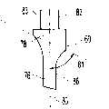
图5是本发明实施例的连接机构的实施例的右侧视图,表示了图1的第二骨折固定植入件的内部;Figure 5 is a right side view of an embodiment of the connecting mechanism of an embodiment of the present invention, showing the interior of the second fracture fixation implant of Figure 1;
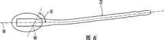
图6是图5的第二植入件的右侧视图;Figure 6 is a right side view of the second implant of Figure 5;
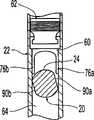
图7是图5的第二植入件的一部分的放大剖视图;Figure 7 is an enlarged cross-sectional view of a portion of the second implant of Figure 5;
图8是图5的连接机构的本体部件的正视图;Fig. 8 is a front view of the body part of the connection mechanism of Fig. 5;
图9是图8的本体部件的左侧视图,其中部分以剖视表示;Fig. 9 is a left side view of the body part of Fig. 8, partly shown in section;
图10是图8的本体部件的右侧视图;Figure 10 is a right side view of the body part of Figure 8;
图11是图8的本体部件的俯视图;Figure 11 is a top view of the body part of Figure 8;
图12A是图5的连接机构的局部剖视图;Fig. 12A is a partial cross-sectional view of the connection mechanism of Fig. 5;
图12B是图5的连接机构的可选实施例的局部剖视图,其中包括两叉头的本体部件;12B is a partial cross-sectional view of an alternative embodiment of the linkage mechanism of FIG. 5 including a body member of a bifurcation;
图13是图5的连接机构的驱动部件的透视图;FIG. 13 is a perspective view of the drive components of the linkage mechanism of FIG. 5;
图14是图13的驱动部件的剖视图;Fig. 14 is a sectional view of the driving part of Fig. 13;
图15是图6的第二植入件的端帽的右侧视图;Figure 15 is the right side view of the end cap of the second implant of Figure 6;
图16是图15的端帽的后视图;Figure 16 is a rear view of the end cap of Figure 15;
图17是用于本发明的植入系统的插入手柄的透视图;以及Figure 17 is a perspective view of an insertion handle for the implant system of the present invention; and
图18是图17的插入手柄的透视图,表示了与图6的第二植入件的连接的情况。18 is a perspective view of the insertion handle of FIG. 17, shown in connection with the second implant of FIG. 6. FIG.
优选实施例的详细说明Detailed Description of the Preferred Embodiment
参考图1,根据本发明一个实施例的骨折固定植入件20表示为植入股骨内,并与第二骨折固定植入件22连接,为了图示目的,该第二骨折固定植入件表示为骨髓钉22。植入件20可以与骨髓钉22或其它骨折固定部件结合使用,以便治疗矫形损伤、接近(impending)骨折和骨折。例如,植入件20可以用于治疗股骨的粗隆间的骨折。植入件20并不局限于与骨髓钉22结合使用,而是可以单独使用或者与任意数目的、本领域普通技术人员已知的植入件、骨板等结合使用。而且,本发明并不局限于治疗股骨,也可以用于治疗人和/或动物的任何骨头。Referring to FIG. 1 , a
参考图2和3,植入件20包括轴24,该轴24有近端26和远端28,且该植入件20还确定了在近端和远端26、28之间的纵向轴线30。多个叶片32布置在轴24上,并绕纵向轴线30螺旋扭转,如后面更详细所述。该多个叶片32有近端34和远端36,且优选是叶片近端34基本位于轴近端26附近。也可选择,叶片32可以位于轴24上并在轴近端和远端26、28之间的中间位置。2 and 3, the
可以选择,中空管38(图3中所示)可以布置在轴24中,并定向成基本与纵向轴线30同轴。如果有,中空管38的尺寸可以设置成能够插入引导线(未视出),以便在植入过程中帮助对齐植入件20,如本领域公知。轴远端28的尺寸可以设置成使它能够安装在插入装置(未视出)例如插入手柄或驱动帽上。例如,如图2和3所示,轴远端28可以相对于轴的纵向轴线30成一定角度和/或包括凹口35,该凹口35有螺纹部分37,用于安装到插入装置上。最好如图1所示,凹口35可以有非对称形状,例如D形,从而使植入件20的旋转方向可以很容易通过远端28来确定。Alternatively, a hollow tube 38 (shown in FIG. 3 ) may be disposed within the
参考图4A-4F,优选是植入件20提供有四个螺旋叶片32a-32d,这四个螺旋叶片绕纵向轴线30扭转。不过,本领域技术人员应当知道,植入件20可以提供有任意数目的叶片32,例如五个、六个或八个叶片。各叶片32a-32d绕纵向轴线30螺旋扭转,图中表示为扭转大约90°。因此,每个叶片在近端34(图4A中所示)和远端36(图4F中所示)之间绕纵向轴线旋转大约90。该螺旋扭转是这样,即一旦植入件20敲入骨(例如股骨)内,叶片32的螺旋扭转将基本防止植入件20沿纵向轴线30在骨中滑动。本领域普通技术人员应当知道,叶片32可以绕纵向轴线30螺旋扭转任意量,例如45°、60°、120°、180°、360°、720°或1080°。Referring to FIGS. 4A-4F , it is preferred that the
如图4A-4F所示,第一叶片32a和第二叶片32c基本绕纵向轴线30彼此径向相对,且第三叶片32b和第四叶片32d也基本绕纵向轴线30彼此径向相对。优选是,第一和第二叶片32a、32c相对于第三和第四叶片32b、32d的相位差为大约90°,不过,其它结构也在本发明范围内。优选是,在一个实施例中,至少一个叶片32确定了沿纵向轴线30变化的叶片宽度W。特别是,叶片32b的叶片宽度Wb从叶片近端34(图4A中所示)向叶片远端(图4F中所示)增加,这样,叶片宽度Wb在邻近叶片远端36处最大,而在邻近叶片近端34处最小。优选是,叶片宽度Wb从近端34向远端36逐渐变大。As shown in FIGS. 4A-4F , the
在所示实施例中,叶片32b和32d都分别有变化的叶片宽度Wb和Wd。当植入件20在骨内处于预定旋转方向时,如图1所示,叶片32b和32d的远端36基本与施加在植入件20上的大部分力所处的平面(即在图1中通过纵向轴线30和纵向轴线68延伸的基本垂直平面)对齐。因此,叶片32b、32d在远端36周围的最大宽度Wb、Wd将增加植入件20的弯曲强度,而在近端34处宽度减小将使植入件20容易插入骨内。叶片32b和32d的锥度将有助于防止植入件20在骨内沿纵向轴线30滑动。In the illustrated embodiment,
另外或者也可选择,一个或多个叶片32可以有基本恒定的叶片宽度W。例如,如图4A-4F所示,叶片32c有基本恒定的宽度Wc,在叶片近端34处(图4A中所示)、在图4B-4F所示的中间点处以及在叶片远端36处(图4F中所示),该宽度基本相等。在所示实施例中,叶片32a也有基本恒定的叶片宽度Wa(在图4A-4F中表示叶片宽度Wa变化是因为叶片高度Ha变化,如后面所述,不过叶片宽度Wa实际上沿纵向轴线30基本恒定)。Additionally or alternatively, one or
根据本发明的另一方面,至少一个叶片32确定了沿纵向轴线30变化的叶片高度H(确定为垂直于纵向轴线30从叶片32的底部到叶片的末端)。特别是,叶片32a可以有从叶片近端34(图4A中所示)至叶片远端36(图4F所示)增加的叶片高度Ha,因此,叶片高度Ha基本在邻近叶片远端36处最大,基本在邻近叶片近端34处最小。优选是,叶片高度Ha在叶片近端34处基本为零,如图4A所示,这样,叶片32a在近端34处基本与轴24平齐。当植入件20处于图1的预定旋转方向时,叶片32a在近端34处的减小高度Ha或基本平齐结构增加了植入件20在完全刺穿骨之前必须在该骨中移动的距离X。还有,叶片32a在近端34处的平齐结构减小了植入件20在骨中的移动(因为当施加负载时,实际上在近端34处没有叶片32来刺穿骨)。According to another aspect of the invention, at least one
另外或者也可选择,至少一个叶片32可以有基本恒定的叶片高度H。例如,如图4A-4F所示,叶片32b、32c和32d分别有基本恒定的叶片高度Hb、Hc和Hd,该叶片高度从叶片近端34(图4A中所示)通过图4B-4E所示的中间点到叶片远端36(图4F所示)都基本恒定。Additionally or alternatively, at least one
参考图3,植入件20包括:有叶片部分40,叶片32布置在该有叶片部分40上;以及无叶片部分42,该无叶片部分42没有任何叶片32。有叶片部分40确定了有叶片直径44,而无叶片部分42确定了无叶片直径46。优选是,有叶片部分40的最大直径(即在最大处的有叶片直径44)小于无叶片部分42的最大直径(即在最大处的无叶片直径46)。根据植入件20的该结构,有叶片部分40可以自由通过在骨髓钉22中的通孔66(图5中所示,并将在后面详细介绍),以便很容易装配,且无叶片部分42可以与孔66匹配,以便在无叶片部分42和孔66之间提供稳定的滑动相互连接。Referring to FIG. 3 , the
无叶片部分42还可以提供有基本位于有叶片部分40附近处的锥形区域48。该锥形区域48确定了沿朝着有叶片部分40的方向减小的锥形区域直径50。例如,锥形区域直径50可以在邻近非锥形区域的位置处等于无叶片直径46,并沿纵向轴线30朝着有叶片部分40的远端变小。优选是,锥形区域48向内弯曲,以便使应力在整个锥形区域48上均匀分布,并使植入件20在负载时均匀弯曲。另外或者也可选择,锥形区域50还可以确定了在基本邻近有叶片部分40的点处(在无叶片部分42与有叶片部分40相交的点处)的颈部直径52,该颈部直径52小于有叶片直径44。植入件20的该结构用于使骨在无叶片部分42和有叶片部分40之间向内生长,从而防止植入件200从骨中退出。此外,锥形区域48用于在植入件20插入骨髓钉22的孔66(图5中所示)内时自定心植入件20。The bladeless portion 42 may also be provided with a tapered region 48 located substantially in the vicinity of the bladed portion 40 . The conical region 48 defines a conical region diameter 50 which decreases in the direction of the bladed part 40 . For example, the tapered region diameter 50 may be equal to the vaneless diameter 46 adjacent the non-tapered region and taper along the
本发明还涉及可以用于使第一骨折固定植入件20与第二骨折固定植入件22连接的机构。如本文所述,连接机构可以用于使上述植入件20与骨髓钉22连接。不过,该连接机构并不局限于用于植入件20和/或骨髓钉22,而是可以用于连接任意数目的、本领域普通技术人员已知的不同骨折固定植入件。The present invention also relates to mechanisms that may be used to connect the first
参考图5,本体部件60和驱动部件62表示为装配在骨髓钉22的内部槽道64中。本体部件60和驱动部件62与槽道64配合,以便将植入件20(未示出)固定在穿过骨髓钉22延伸的孔66中。如后面更详细所述,本体部件60。驱动部件62和槽道64配合,以便基本防止植入件20在孔66内绕它的纵向轴线30(图1-3中所示)旋转,并将植入件20在孔66中的滑动限制在移动距离内。Referring to FIG. 5 , the
参考图6和7,图中详细表示了骨髓钉22的结构。骨髓钉22确定了纵向轴线68,该纵向轴线可以为直线形、曲线形(图中所示)、弯曲形状或者其它形状,且该骨髓钉22的结构和尺寸设置成与它将植入的骨的几何形状匹配。槽道64基本沿纵向轴线68延伸,且尺寸和结构设置成接收本体部件60和驱动部件62,这样,两个部件可以在槽道64内沿纵向轴线68至少部分运动。一系列螺纹98可以布置在槽道64上,如后面详细所述。还有,一对槽65可以形成于槽道64上,优选是该对槽65彼此径向相对。Referring to Figures 6 and 7, the structure of the
还是参考图6和7,孔66穿过骨髓钉22延伸,并与槽道64相交,且该孔66的尺寸和结构设置成使得植入件20能够滑过。根据所示实施例,孔66的尺寸和结构设置成与植入件20的无叶片部分42滑动啮合,并使植入件20保持与纵向轴线68成角度关系。如图所示,孔66布置成与纵向轴线68成角度70。角度70可以选择成与骨髓钉22和植入件20要植入的病人的解剖学结构匹配,例如与病人的股骨颈/轴角度相同。中空管72(部分在图7中所示)可选择地布置成以与纵向轴线68基本同轴对齐的方式通过骨髓钉22。如果有,中空管72的尺寸可以设置成能够插入引导线(未视出),以便引导将骨髓钉22植入骨中,如本领域公知。Still referring to FIGS. 6 and 7 , a
参考图8-11,图中详细表示了本体部件60。本体部件60包括:基本柱形部分78,该基本柱形部分78确定了本体部件60的纵向轴线80;以及叉头76,该叉头76从柱形部分78上伸出。不过,本领域普通技术人员应当知道,本体部件60并不局限于所示形状,它可以为允许本体部件60在骨髓钉22的槽道64中运动的任意形状。一对对齐的凸耳85(图8和11中所示)可以从柱形部分78上伸出。如果有,凸耳85位于本体部件60上,这样,凸耳85可以装入骨髓钉22的槽65(图7中所示)中。凸耳85和槽65之间的配合基本限制了本体部件60在骨髓钉22的槽道64中的旋转。Referring to Figures 8-11, the
凸耳85和槽65之间的配合还在连接机构装配和锁定好时使本体部件60的表面79(图9中所示)保持离植入件20一定距离,从而允许植入件20在孔66中自由滑动。更具体地说,槽65的端部67(图7中所示)与凸耳85接触,并防止本体部件60朝着孔66进一步滑动。端部67位于槽道64中并处于这样的位置,即当表面79与植入件20接触之前,凸耳85与端部67接触(以便防止本体部件60朝着孔66进一步运动)。如图所示,优选是表面79相对于纵向轴线80定向成一定角度81,该角度81基本等于角度70,不过该角度81也可以不同于角度70。根据该结构,角度81基本等于角度70,当连接机构装配和锁定好时,成角度的表面79保持距离植入件20恒定距离。The cooperation between the
本体部件60还可以包括安装部分82,该安装部分82的尺寸和结构设置成使本体部件60与驱动部件62可旋转地连接,如后面更详细所述。如图8所示,安装部分82包括一对向上延伸的臂83,该臂83确定了一对相对槽道83a,用于在其中容纳驱动部件62的一部分。中空管84可选择地布置成以与纵向轴线80基本同轴对齐的方式通过本体部件60,以便使引导线(未示出)能够穿过插入。
还是参考图8-11,叉头76沿基本平行于纵向轴线80的方向从本体部件60上伸出,且它的尺寸和结构可以设置成与植入件20接触,以便限制植入件20相对于纵向轴线30(图1中所示)的滑动和旋转。如下面更详细所述,叉头76可以提供有第一啮合表面86,该第一啮合表面86与形成于植入件20上的第二啮合表面90接触,以便基本防止植入件20的旋转,并限制植入件20的滑动,如后面更详细所述。根据本发明的可选实施例,本体部件60可以提供有两个或更多叉头,以便与形成于植入件20上的两个或更多啮合表面接触。例如,第二叉头可以沿与叉头76相同的方向从本体部件60上伸出,并可以相对纵向轴线80与叉头76径向相对和基本平行于叉头76。例如,两叉头实施例可以用于具有两个径向相对啮合表面的植入件20。也可选择,单叉头实施例可以用于具有两个或更多啮合表面的植入件20。Still referring to FIGS. 8-11 , prongs 76 protrude from
参考图2和3,图中表示了形成于植入件20上的第二啮合表面90的示例实施例。根据所示实施例,第二啮合表面90基本平直并沿纵向轴线30延伸。第一和第二止动器92、94可以位于锁定第二啮合表面90的相对端。在所示实施例中,第二啮合表面90凹入植入件20的轴24内,且止动器92、94形成于凹入表面的边界处。不过,本领域普通技术人员应当知道,其它结构的啮合表面90和止动器92、94也在本发明的范围内。例如,也可选择,啮合表面90和/或止动器92、94可以形成于轴24上或从该轴24上延伸。而且,如上所述,也可选择植入件20可以提供有两个或更多第二啮合表面90,这些啮合表面90可以与具有一个、两个或更多叉头的本体部件60相互作用。Referring to Figures 2 and 3, an example embodiment of a
当植入件20安装在骨髓钉22中的孔66内,本体部件60位于槽道64内,且凸耳85降低至槽65的端部67上时,叉头76与植入件20相互作用,以便基本防止植入件20绕它的纵向轴线30旋转。更具体地说,叉头76紧配合安装在槽道64和植入件20之间的空间内,这样,在槽道64的约束下,第一和第二啮合表面86、90保持接触。在该结构中,由于基本平直的第一和第二啮合表面86、90的抵靠,将基本防止植入件20绕它的纵向轴线30旋转。因此,连接机构可以用于将植入件20保持在骨内的预定旋转方向。如果有,止动器92、94将防止植入件20和植入件22离开,还可以将植入件20沿它的纵向轴线30的滑动量限制为第二啮合表面90的长度。例如,当植入件20向远侧滑动直到第一止动器92与叉头76接触时,将防止沿向远侧方向的进一步滑动。同样,当植入件20向近侧滑动直到第二止动器94与叉头76接触时,将防止沿向近侧方向的进一步滑动。因此,第一和第二止动器92、94可以选择地沿纵向轴线30间开,以便提供在植入件20和骨髓钉22之间的合适滑动量,以便用于在两个骨折骨段之间的挤压。例如,在植入过程中,可能希望进行有限滑动,以便将骨折的股骨头部压向转节(trochanteric)区域。另外,有限运动也可以用于刺激骨生长和骨折治愈。本领域普通技术人员应当知道,第一啮合表面86和第二啮合表面90并不局限于这里所示的基本平直结构。而且,第一和第二啮合表面86、90可以有任意几何形状,当布置成彼此邻近时,该几何形状将防止植入件20绕轴线30旋转,还用于使植入件20沿纵向轴线30滑动。
如上所述,本体部件60可以有两个或更多叉头76,且植入件20可以有两个或更多啮合表面90。尽管在某些场合(例如当非常大的力将使第一植入件20绕它的纵向轴线30相对于第二植入件22旋转时)中希望能够有多个叉头,但是如图8-10中所示具有单个叉头76的示例实施例或者一个叉头比其它叉头更长的可选实施例将比具有相同长度叉头的两叉头或多叉头实施例更容易装配。例如,在图12A所示的情况下(这时植入件20与孔66没有对齐,从而使第一啮合表面86与第二啮合表面并没有对齐),单个叉头76或者一个叉头比其它叉头更长时将很有利。这时,使本体部件60朝着植入件20运动将使得叉头76沿第二啮合表面90滑动,以便使植入件20绕纵向轴线30旋转,直到第一和第二啮合表面86、90彼此平齐并且啮合,以便基本防止植入件20的旋转。相反,当如图12B所示具有相同长度叉头的两叉头实施例朝着并没有与孔66对齐的植入件20运动时,一个叉头76与轴24接触,并防止另一叉头76与相应第二啮合表面90接触以便使植入件20旋转成对齐状态。如图所示,第二叉头76b与轴24接触,并防止第一叉头76a与第二啮合表面90a接触以便使植入件20旋转成与本体部件60合适对齐。因此,为了使连接机构更容易装配,可以提供单叉头实施例(或者一个叉头比其它叉头更长的多叉头实施例)。As noted above, the
参考图7、8和11,如果有凸耳85,该凸耳85与槽65配合,以便基本防止本体部件60在骨髓钉22的槽道64中旋转。这有利于使叉头76与在槽道64中的啮合表面90对齐;因此,植入件20可以很容易插入孔66内,同时不需要外科医生来解决叉头76对齐的问题。Referring to FIGS. 7 , 8 and 11 ,
参考图13和14,图中详细表示了驱动部件62。驱动部件62的结构和尺寸设置成与槽道64啮合,以便选择地使本体部件60保持就位。在所示实施例中,驱动部件62包括一系列螺纹96,该螺纹96与形成于槽道64中的一系列螺纹98匹配,不过,用于将驱动部件62固定在槽道64内的其它结构例如弹簧或弹性体也在本发明范围内。驱动部件62还包括安装部分100,该安装部分100的结构和尺寸设置成使驱动部件62可旋转地与本体部件60连接,这样,驱动部件62可以相对于本体部件60自由旋转。这在凸耳85(图8和11)与槽65(图7)配合以防止本体部件60在槽道64中旋转时的情况下特别有利。在所示实施例中,安装部分100为基本盘形凸缘,该凸缘可以安装在形成于本体部件60的臂83中的槽道83a之间。本领域普通技术人员应当知道,也可选择,任意数量的结构可以用于使驱动部件62与本体部件60连接,并用于在这两个部件之间旋转,例如螺钉、旋转接头、销等。本领域普通技术人员应当知道,本体部件60和驱动部件62既可以相互永久性安装,也可以相互可拆卸地连接。驱动部件62还可以包括工具啮合部分102。如图所示,驱动部件62确定了基本六边形开口102,该六边形开口102的尺寸和结构设置成与六边形键啮合。也可选择,工具啮合部分102的尺寸和结构可以与本领域普通技术人员已知的任意驱动工具(例如螺丝刀或扳手)啮合。空心管104可以选择基本轴向穿过驱动部件62延伸,以便使引导线(未示出)能够穿过插入。Referring to Figures 13 and 14, the
参考图15和16,图中表示了可选的端帽。如果有,端帽106可拆卸地安装在骨髓钉22的端部上,以便隐蔽在槽道64中的本体部件60和驱动部件62。此外,当外科医生选择并不使锁定结构啮合(即并不在槽道64中紧固驱动部件62以便使本体部件60与植入件20啮合)时,端帽106可以压靠驱动部件62,以便防止驱动部件62意外进入槽道64,并因此防止本体部件60进入槽道64。Referring to Figures 15 and 16, optional end caps are shown. If present,
在图15和16所示的实施例中,端帽106包括布置在它上面的一系列螺纹108,这些螺纹与形成于槽道64上的一系列螺纹98配合,或者与形成于槽道64上的另一系列螺纹配合,以便将端帽106固定在骨髓钉22上。也可选择使用本领域普通技术人员已知的任意结构(包括卡扣紧固件、粘接剂或螺钉)来将端帽106可拆卸地安装在骨髓钉22上。端帽106还包括工具啮合部分110,图中表示为基本六边形部分110,该工具啮合部分110的尺寸和结构设置成与扳手啮合。也可选择,工具啮合部分110的尺寸和结构可以设置成与本领域普通技术人员已知的任意驱动工具啮合,例如六边形键或螺丝刀。也可选择,可以提供有空心管112,该空心管112基本轴向穿过端帽106延伸,以便使引导线(未示出)能够穿过插入。In the embodiment shown in FIGS. 15 and 16 , the
骨髓钉22可以提供有本体部件60、驱动部件62以及可选的端帽106,该端帽106预安装在槽道64中,因此,植入骨髓钉22的时间减少,同时减少了外科医生必须处置的部件数目。当这些部件预装配时,空心管72、84、104和112(分别布置在骨髓钉22、本体部件60、驱动部件62和帽106中)可以基本对齐,以便使用于引导骨髓钉22的引导线可以穿过该预装配单元插入。因此,引导线可以用于引导骨髓钉22(包括预装配的锁定部件)到骨折骨的骨髓腔内。The
如图17和18所示,也可选择提供有插入手柄120,以便帮助插入第二植入件(例如骨髓钉22)。如图所示,插入手柄120包括手柄部分22和连接部分124。连接部分124可以包括孔125,该孔125的尺寸和结构设置成接收连接螺钉126。连接螺钉126可以穿过孔125插入,并螺纹连接到槽道64的螺纹98中,以便使插入手柄120与骨髓钉22可拆卸地连接。不过,本领域技术人员应当知道,其它结构也可以用于使插入手柄120与骨髓钉22可拆卸地连接。当安装在骨髓钉22上时,插入手柄120可以用于帮助将骨髓钉22插入骨髓腔内。中空管128可选择地布置在连接螺钉126中,并与(上述)中空管72、84和104对齐,以便能够使用插入手柄120来越过引导线插入骨髓钉22。而且,连接螺钉126的长度L(图17中所示)可以选择为使得插入手柄120可以与其中预装配有本体部件60和驱动部件62的骨髓钉22连接。As shown in Figures 17 and 18, an
尽管这里已经介绍了骨植入件和连接机构的优选实施例和特征,但是本领域技术人员可以设计出多种变化形式和实施例。附加权利要求将覆盖落在这些权利要求的真正精神和范围内的所有这些变化形式和实施例,且权利要求并不局限于这些优选实施例或特征。Although preferred embodiments and features of the bone implant and connection mechanism have been described herein, numerous variations and embodiments can be devised by those skilled in the art. The appended claims are to cover all such modifications and embodiments as fall within the true spirit and scope of these claims, and the claims are not limited to these preferred embodiments or features.
Claims (34)
Translated fromChineseApplications Claiming Priority (2)
| Application Number | Priority Date | Filing Date | Title |
|---|---|---|---|
| US09/978,002 | 2001-10-17 | ||
| US09/978,002US6835197B2 (en) | 2001-10-17 | 2001-10-17 | Bone fixation system |
Publications (2)
| Publication Number | Publication Date |
|---|---|
| CN1571652A CN1571652A (en) | 2005-01-26 |
| CN1301088Ctrue CN1301088C (en) | 2007-02-21 |
Family
ID=25525720
Family Applications (1)
| Application Number | Title | Priority Date | Filing Date |
|---|---|---|---|
| CNB028205758AExpired - LifetimeCN1301088C (en) | 2001-10-17 | 2002-10-16 | Bone fixation system |
Country Status (22)
| Country | Link |
|---|---|
| US (7) | US6835197B2 (en) |
| EP (1) | EP1435862B1 (en) |
| JP (1) | JP4230909B2 (en) |
| KR (1) | KR100953149B1 (en) |
| CN (1) | CN1301088C (en) |
| AR (1) | AR036895A1 (en) |
| AT (1) | ATE294539T1 (en) |
| AU (1) | AU2002340218B2 (en) |
| BR (1) | BR0213399A (en) |
| CA (1) | CA2463514C (en) |
| CO (1) | CO5570643A2 (en) |
| DE (1) | DE60204034T2 (en) |
| ES (1) | ES2240821T3 (en) |
| IL (1) | IL160923A0 (en) |
| MX (1) | MXPA04003469A (en) |
| NO (1) | NO20042026L (en) |
| NZ (1) | NZ531997A (en) |
| PT (1) | PT1435862E (en) |
| RU (1) | RU2004114870A (en) |
| TW (1) | TWI248807B (en) |
| WO (1) | WO2003032853A2 (en) |
| ZA (1) | ZA200402301B (en) |
Families Citing this family (139)
| Publication number | Priority date | Publication date | Assignee | Title |
|---|---|---|---|---|
| US8070786B2 (en)* | 1993-01-21 | 2011-12-06 | Acumed Llc | System for fusing joints |
| US9161793B2 (en) | 1993-01-21 | 2015-10-20 | Acumed Llc | Axial tension screw |
| US7179260B2 (en)* | 2003-09-29 | 2007-02-20 | Smith & Nephew, Inc. | Bone plates and bone plate assemblies |
| US20060155281A1 (en)* | 2002-10-01 | 2006-07-13 | Thomas Kaup | Device for fixing bones |
| WO2004039270A1 (en)* | 2002-10-29 | 2004-05-13 | Mathys Medizinaltechnik Ag | Device for the treatment of fractures of the femur |
| EP1415605B1 (en)* | 2002-11-04 | 2010-10-13 | Zimmer GmbH | Bone fixation system |
| EP1601297B1 (en)* | 2003-03-07 | 2013-07-17 | Synthes GmbH | Locking screw for an intramedullary nail |
| US7951176B2 (en) | 2003-05-30 | 2011-05-31 | Synthes Usa, Llc | Bone plate |
| WO2004110291A1 (en)* | 2003-06-12 | 2004-12-23 | Synthes Ag Chur | Surgical nail |
| ES2348003T3 (en)* | 2003-06-12 | 2010-11-26 | Synthes Gmbh | SURGICAL KEY. |
| ES2319179T3 (en)* | 2003-07-30 | 2009-05-05 | Synthes Gmbh | SURGICAL KEY. |
| US11259851B2 (en) | 2003-08-26 | 2022-03-01 | DePuy Synthes Products, Inc. | Bone plate |
| DE20321551U1 (en) | 2003-08-26 | 2007-12-27 | Synthes Gmbh | bone plate |
| NZ545342A (en) | 2003-08-29 | 2008-11-28 | Synthes Gmbh | Intramedullary nail |
| US7780667B2 (en) | 2003-09-08 | 2010-08-24 | Smith & Nephew, Inc. | Orthopaedic plate and screw assembly |
| US20050055024A1 (en)* | 2003-09-08 | 2005-03-10 | James Anthony H. | Orthopaedic implant and screw assembly |
| US7799030B2 (en)* | 2003-09-08 | 2010-09-21 | Smith & Nephew, Inc. | Orthopaedic plate and screw assembly |
| CN100393287C (en)* | 2003-09-18 | 2008-06-11 | 斯恩蒂斯有限公司 | Device for treating femoral fractures |
| ES2340479T3 (en)* | 2003-10-21 | 2010-06-04 | Synthes Gmbh | INTRAMEDULAR KEY. |
| US7601153B2 (en)* | 2003-12-25 | 2009-10-13 | Homs Engineering Inc. | Intramedullary nail |
| US11291484B2 (en) | 2004-01-26 | 2022-04-05 | DePuy Synthes Products, Inc. | Highly-versatile variable-angle bone plate system |
| US8574268B2 (en) | 2004-01-26 | 2013-11-05 | DePuy Synthes Product, LLC | Highly-versatile variable-angle bone plate system |
| US7837709B2 (en)* | 2004-03-03 | 2010-11-23 | Synthes Usa, Llc | Bone fixation means |
| US8092454B2 (en) | 2004-03-11 | 2012-01-10 | Sohngen Gary W | Fixation instrument for treating a bone fracture |
| US7033363B2 (en) | 2004-05-19 | 2006-04-25 | Sean Powell | Snap-lock for drill sleeve |
| US7033365B2 (en)* | 2004-06-02 | 2006-04-25 | Synthes (Usa) | Implant assembly device |
| ATE426366T1 (en)* | 2004-06-22 | 2009-04-15 | Synthes Gmbh | INTRAMEDULLAR INTRAMEDULLAR NAIL |
| WO2006000109A1 (en)* | 2004-06-24 | 2006-01-05 | Synthes Gmbh | Intramedullary nail |
| CA2571508C (en)* | 2004-06-30 | 2012-03-13 | Synthes (U.S.A.) | Surgical nail |
| US20060036248A1 (en)* | 2004-07-01 | 2006-02-16 | Ferrante Joseph M | Fixation elements |
| US8425570B2 (en) | 2004-08-09 | 2013-04-23 | Si-Bone Inc. | Apparatus, systems, and methods for achieving anterior lumbar interbody fusion |
| US8470004B2 (en) | 2004-08-09 | 2013-06-25 | Si-Bone Inc. | Apparatus, systems, and methods for stabilizing a spondylolisthesis |
| US8444693B2 (en) | 2004-08-09 | 2013-05-21 | Si-Bone Inc. | Apparatus, systems, and methods for achieving lumbar facet fusion |
| US20060036251A1 (en) | 2004-08-09 | 2006-02-16 | Reiley Mark A | Systems and methods for the fixation or fusion of bone |
| US9949843B2 (en) | 2004-08-09 | 2018-04-24 | Si-Bone Inc. | Apparatus, systems, and methods for the fixation or fusion of bone |
| US9662158B2 (en)* | 2004-08-09 | 2017-05-30 | Si-Bone Inc. | Systems and methods for the fixation or fusion of bone at or near a sacroiliac joint |
| US20070156241A1 (en) | 2004-08-09 | 2007-07-05 | Reiley Mark A | Systems and methods for the fixation or fusion of bone |
| US8414648B2 (en) | 2004-08-09 | 2013-04-09 | Si-Bone Inc. | Apparatus, systems, and methods for achieving trans-iliac lumbar fusion |
| US20180228621A1 (en) | 2004-08-09 | 2018-08-16 | Mark A. Reiley | Apparatus, systems, and methods for the fixation or fusion of bone |
| US8388667B2 (en) | 2004-08-09 | 2013-03-05 | Si-Bone, Inc. | Systems and methods for the fixation or fusion of bone using compressive implants |
| DE202004014288U1 (en)* | 2004-09-15 | 2004-11-18 | Stryker Trauma Gmbh | Intra-medullary locking nail |
| US20060200160A1 (en)* | 2005-02-18 | 2006-09-07 | Ebi, L.P. | Internal fixation assemblies and associated instruments |
| GB0504382D0 (en)* | 2005-03-03 | 2005-04-06 | Depuy Int Ltd | Intra-medullary fixation device |
| US9192398B2 (en)* | 2005-09-19 | 2015-11-24 | DePuy Synthes Products, Inc. | Orthopedic implant insertion handle and aiming guide |
| US20080249580A1 (en)* | 2005-09-28 | 2008-10-09 | Smith & Nephew, Inc. | Methods and Instruments of Reducing a Fracture |
| US8192449B2 (en)* | 2005-10-25 | 2012-06-05 | Brainlab Ag | Non-penetrating fixing device |
| US20070155271A1 (en)* | 2005-12-30 | 2007-07-05 | Touzov Igor V | Heat conductive textile and method producing thereof |
| US20070270846A1 (en)* | 2006-03-31 | 2007-11-22 | Metzinger Anthony J | Fixture, intramedullary nail kit and method of presetting a nail assembly |
| US20080003255A1 (en) | 2006-05-10 | 2008-01-03 | Synthes (Usa) | Method for augmenting, reducing, and repairing bone with thermoplastic materials |
| US20090198237A1 (en)* | 2006-05-10 | 2009-08-06 | David Downey | Method for augmenting, reducing, and repairing bone with thermoplastic materials |
| WO2008064059A2 (en)* | 2006-11-17 | 2008-05-29 | Synthes(U.S.A.) | Sliding hip helical implant |
| US8579985B2 (en) | 2006-12-07 | 2013-11-12 | Ihip Surgical, Llc | Method and apparatus for hip replacement |
| EP2094197B8 (en) | 2006-12-07 | 2016-03-09 | IHip Surgical, LLC | Apparatus for total hip replacement |
| US8974540B2 (en) | 2006-12-07 | 2015-03-10 | Ihip Surgical, Llc | Method and apparatus for attachment in a modular hip replacement or fracture fixation device |
| US8157802B2 (en) | 2007-01-26 | 2012-04-17 | Ebi, Llc | Intramedullary implant with locking and compression devices |
| US9320551B2 (en) | 2007-01-26 | 2016-04-26 | Biomet Manufacturing, Llc | Lockable intramedullary fixation device |
| US8303590B2 (en)* | 2007-01-26 | 2012-11-06 | Ebi, Llc | Lockable intramedullary fixation device |
| US9308031B2 (en) | 2007-01-26 | 2016-04-12 | Biomet Manufacturing, Llc | Lockable intramedullary fixation device |
| US7918853B2 (en)* | 2007-03-20 | 2011-04-05 | Smith & Nephew, Inc. | Orthopaedic plate and screw assembly |
| AU2008256740A1 (en) | 2007-05-25 | 2008-12-04 | Zimmer, Gmbh | Reinforced intramedullary nail |
| US8157803B1 (en) | 2007-08-21 | 2012-04-17 | Surgical Implant Generation Network | Bone fixation using an intramedullary nail interlocked with a buttress member |
| US8394103B2 (en) | 2007-10-16 | 2013-03-12 | Biomet Manufacturing Corp. | Method and apparatus for orthopedic fixation |
| CN101854873B (en)* | 2007-11-13 | 2013-03-13 | 新特斯有限责任公司 | Periprosthetic fracture repair |
| US8092505B2 (en)* | 2008-01-28 | 2012-01-10 | Acumed Llc | Bone nail |
| CN104068925B (en) | 2008-03-26 | 2017-07-14 | 斯恩蒂斯有限公司 | For the universal anchor by physical attachment on bone tissue |
| CN102046111A (en) | 2008-06-05 | 2011-05-04 | 斯恩蒂斯有限公司 | Articulating disc implant |
| US8668694B2 (en) | 2008-06-06 | 2014-03-11 | Steven M. Teeny | Bone fixation assemblies and methods of use |
| ES2524076T3 (en) | 2008-10-15 | 2014-12-04 | Zimmer Gmbh | Intramedullary nail |
| US8808292B2 (en)* | 2008-11-11 | 2014-08-19 | Zimmer Gmbh | Orthopedic screw |
| US9060808B2 (en)* | 2008-12-05 | 2015-06-23 | DePuy Synthes Products, Inc. | Anchor-in-anchor system for use in bone fixation |
| US9295504B2 (en) | 2009-03-31 | 2016-03-29 | Biomet C.V. | Intramedullary nail with locking key |
| US8216237B2 (en)* | 2009-06-04 | 2012-07-10 | Edwards Scott G | Intramedullary device assembly and associated method |
| US8449544B2 (en) | 2009-06-30 | 2013-05-28 | Smith & Nephew, Inc. | Orthopaedic implant and fastener assembly |
| US8834469B2 (en) | 2009-06-30 | 2014-09-16 | Smith & Nephew, Inc. | Orthopaedic implant and fastener assembly |
| CN101601605B (en)* | 2009-07-14 | 2011-01-05 | 常州市康辉医疗器械有限公司 | Intramedullary nail fixation device for fractured near end of thighbone |
| JP5497194B2 (en) | 2009-12-11 | 2014-05-21 | スモール・ボーン・イノベーションズ・インコーポレーテッド | Ankle fusion device, instrument, and method |
| EP2455014B1 (en) | 2010-11-17 | 2015-08-12 | Hyprevention | Implantable device for preventive or interventive treatment of femur fractures, associated ancillary device |
| CA2825444C (en) | 2011-02-08 | 2016-01-12 | Stryker Trauma Gmbh | Implant system for bone fixation |
| US9044321B2 (en) | 2012-03-09 | 2015-06-02 | Si-Bone Inc. | Integrated implant |
| US8778026B2 (en) | 2012-03-09 | 2014-07-15 | Si-Bone Inc. | Artificial SI joint |
| USD680221S1 (en)* | 2012-03-09 | 2013-04-16 | Yechiel Gotfried | Surgical nail |
| US10363140B2 (en) | 2012-03-09 | 2019-07-30 | Si-Bone Inc. | Systems, device, and methods for joint fusion |
| AU2013232339B2 (en)* | 2012-03-14 | 2017-11-02 | Synthes Gmbh | Pelvic bone plate |
| EP3818947B1 (en) | 2012-05-04 | 2023-08-30 | SI-Bone, Inc. | Fenestrated implant |
| WO2014145902A1 (en) | 2013-03-15 | 2014-09-18 | Si-Bone Inc. | Implants for spinal fixation or fusion |
| USD714938S1 (en) | 2013-08-01 | 2014-10-07 | Yechiel Gotfried | Surgical nail |
| US11147688B2 (en) | 2013-10-15 | 2021-10-19 | Si-Bone Inc. | Implant placement |
| US9839448B2 (en) | 2013-10-15 | 2017-12-12 | Si-Bone Inc. | Implant placement |
| US10080596B2 (en) | 2013-12-09 | 2018-09-25 | Acumed Llc | Hip fixation with load-controlled dynamization |
| US9463055B2 (en) | 2013-12-09 | 2016-10-11 | Acumed Llc | Plate-based compliant hip fixation system |
| US9433451B2 (en) | 2013-12-09 | 2016-09-06 | Acumed Llc | Hip fixation system with a compliant fixation element |
| ES2805053T3 (en) | 2013-12-09 | 2021-02-10 | Acumed Llc | Nail-based elastic hip fixation system |
| US9526542B2 (en)* | 2014-05-07 | 2016-12-27 | Acumed Llc | Hip fixation with load-controlled dynamization |
| US10045803B2 (en) | 2014-07-03 | 2018-08-14 | Mayo Foundation For Medical Education And Research | Sacroiliac joint fusion screw and method |
| US10166033B2 (en) | 2014-09-18 | 2019-01-01 | Si-Bone Inc. | Implants for bone fixation or fusion |
| JP6542362B2 (en) | 2014-09-18 | 2019-07-10 | エスアイ−ボーン・インコーポレイテッドSi−Bone, Inc. | Matrix implant |
| DE102014113556A1 (en)* | 2014-09-19 | 2016-03-24 | Königsee Implantate GmbH | Osteosynthesis aids for the treatment of subtrochanteric fractures and / or pertrochanteric fractures and / or femoral neck fractures |
| US10376206B2 (en) | 2015-04-01 | 2019-08-13 | Si-Bone Inc. | Neuromonitoring systems and methods for bone fixation or fusion procedures |
| US20220151664A1 (en)* | 2015-04-16 | 2022-05-19 | Texas Tech University System | Ankle (Tibio-Talar) Fusion Nail |
| US11253298B2 (en) | 2015-05-22 | 2022-02-22 | Stryker European Operations Holdings Llc | Implant system for bone fixation |
| TWI589263B (en)* | 2015-06-04 | 2017-07-01 | 愛派司生技股份有限公司 | A fixation system for hip fracture use thereof |
| US10357314B2 (en) | 2015-07-08 | 2019-07-23 | Stryker European Holdings I, Llc | Instrumentation and method for repair of a bone fracture |
| TWI572317B (en)* | 2015-08-05 | 2017-03-01 | 梓源生技有限公司 | In vivo fixation device |
| US11213334B2 (en) | 2015-10-07 | 2022-01-04 | Stabiliz Orthopaedics, LLC | Bone fracture fixation device with transverse set screw and aiming guide |
| US9895177B2 (en) | 2016-01-15 | 2018-02-20 | ARTHREX, GmbH | Bone fixation device for treatment of femoral fractures |
| US9833321B2 (en) | 2016-04-25 | 2017-12-05 | Imds Llc | Joint fusion instrumentation and methods |
| US10413332B2 (en) | 2016-04-25 | 2019-09-17 | Imds Llc | Joint fusion implant and methods |
| CN106073877A (en)* | 2016-07-14 | 2016-11-09 | 闻泰医疗科技(上海)有限公司 | A kind of near end of thighbone Medullary fixation device |
| US10905476B2 (en) | 2016-09-08 | 2021-02-02 | DePuy Synthes Products, Inc. | Variable angle bone plate |
| US10820930B2 (en) | 2016-09-08 | 2020-11-03 | DePuy Synthes Products, Inc. | Variable angle bone plate |
| US10624686B2 (en) | 2016-09-08 | 2020-04-21 | DePuy Synthes Products, Inc. | Variable angel bone plate |
| US10492803B2 (en) | 2016-09-22 | 2019-12-03 | Globus Medical, Inc. | Systems and methods for intramedullary nail implantation |
| US10299847B2 (en)* | 2016-09-22 | 2019-05-28 | Globus Medical, Inc. | Systems and methods for intramedullary nail implantation |
| US11083503B2 (en) | 2016-09-22 | 2021-08-10 | Globus Medical, Inc. | Systems and methods for intramedullary nail implantation |
| EP3391841A1 (en) | 2017-04-20 | 2018-10-24 | Stöckli Group AG | Longitudinal bone implant |
| US10474771B2 (en)* | 2017-06-19 | 2019-11-12 | Honeywell International Inc. | Calculation order management for a sequential-modular process simulator |
| US11116519B2 (en) | 2017-09-26 | 2021-09-14 | Si-Bone Inc. | Systems and methods for decorticating the sacroiliac joint |
| US11026727B2 (en) | 2018-03-20 | 2021-06-08 | DePuy Synthes Products, Inc. | Bone plate with form-fitting variable-angle locking hole |
| ES3011907T3 (en) | 2018-03-28 | 2025-04-08 | Si Bone Inc | Threaded implants for use across bone segments |
| US10772665B2 (en) | 2018-03-29 | 2020-09-15 | DePuy Synthes Products, Inc. | Locking structures for affixing bone anchors to a bone plate, and related systems and methods |
| US11013541B2 (en) | 2018-04-30 | 2021-05-25 | DePuy Synthes Products, Inc. | Threaded locking structures for affixing bone anchors to a bone plate, and related systems and methods |
| JP7381036B2 (en)* | 2018-12-11 | 2023-11-15 | 株式会社ホムズ技研 | bone fixation system |
| US10925651B2 (en) | 2018-12-21 | 2021-02-23 | DePuy Synthes Products, Inc. | Implant having locking holes with collection cavity for shavings |
| US11369419B2 (en) | 2019-02-14 | 2022-06-28 | Si-Bone Inc. | Implants for spinal fixation and or fusion |
| EP4613244A2 (en) | 2019-02-14 | 2025-09-10 | SI-Bone Inc. | Implants for spinal fixation and or fusion |
| US11633219B2 (en) | 2019-06-26 | 2023-04-25 | Globus Medical, Inc. | Fenestrated pedicle nail |
| US11510719B2 (en)* | 2019-09-05 | 2022-11-29 | DePuy Synthes Products, Inc. | Intramedullary nail retaining endcaps |
| KR102276643B1 (en) | 2019-11-11 | 2021-07-13 | 주식회사 제일메디칼코퍼레이션 | Leg screw for bone fixation having separate structure |
| JP7646654B2 (en) | 2019-11-21 | 2025-03-17 | エスアイ-ボーン・インコーポレイテッド | Rod coupling assembly for bone stabilization construct - Patent application |
| AU2020392121B2 (en) | 2019-11-27 | 2025-05-22 | Si-Bone, Inc. | Bone stabilizing implants and methods of placement across SI joints |
| EP4072452A4 (en) | 2019-12-09 | 2023-12-20 | SI-Bone, Inc. | Sacro-iliac joint stabilizing implants and methods of implantation |
| US12207849B2 (en) | 2020-03-06 | 2025-01-28 | Stryker European Operations Limited | Set screw for femoral nail |
| WO2021176272A1 (en) | 2020-03-06 | 2021-09-10 | Stryker European Operations Limited | Set screw for femoral nail |
| JP2022034191A (en)* | 2020-08-18 | 2022-03-03 | 株式会社日本エム・ディ・エム | End cap used for intramedullary nail, intramedullary nail, end cap insertion instrument, and intramedullary nail insertion instrument |
| EP4259015A4 (en) | 2020-12-09 | 2024-09-11 | SI-Bone, Inc. | SACROILIAC JOINT STABILIZATION IMPLANTS AND METHODS OF IMPLANTATION |
| US11701132B2 (en) | 2021-03-25 | 2023-07-18 | DePuy Synthes Products, Inc. | Lateral cortex penetrator |
| DE102021001608B4 (en) | 2021-03-26 | 2025-01-23 | Mimeo Medical Gmbh | surgical drilling instrument |
| EP4346658A4 (en)* | 2021-05-28 | 2025-04-23 | Acumed LLC | Bone fixation systems and nail having compressive threading |
| WO2025038769A1 (en) | 2023-08-15 | 2025-02-20 | Si-Bone Inc. | Pelvic stabilization implants, methods of use and manufacture |
Citations (3)
| Publication number | Priority date | Publication date | Assignee | Title |
|---|---|---|---|---|
| US5120171A (en)* | 1990-11-27 | 1992-06-09 | Stuart Surgical | Bone screw with improved threads |
| CN1244105A (en)* | 1997-01-13 | 2000-02-09 | 库尔斯恩蒂斯股份公司 | Helical osteosynthetic implant |
| WO2000067653A1 (en)* | 1999-05-11 | 2000-11-16 | S.I.N.A.I. Medical Technologies Ltd. | Universal hip compression device |
Family Cites Families (73)
| Publication number | Priority date | Publication date | Assignee | Title |
|---|---|---|---|---|
| US2834342A (en) | 1956-08-29 | 1958-05-13 | Clyde E Yost | Surgical device for the fixation of fractured bones |
| US3112743A (en) | 1960-09-01 | 1963-12-03 | Orthopaedic Specialties Corp | Method for treatment of bone fractures |
| US3433220A (en) | 1966-12-30 | 1969-03-18 | Robert E Zickel | Intramedullary rod and cross-nail assembly for treating femur fractures |
| US3848272A (en)* | 1972-01-13 | 1974-11-19 | United States Surgical Corp | Artificial hip joint |
| US4095591A (en) | 1977-01-27 | 1978-06-20 | Richards Manufacturing Co., Inc. | Compression screw system |
| US4103683A (en) | 1977-06-03 | 1978-08-01 | Neufeld John A | Sub-trochanteric nail |
| US4172452A (en) | 1978-05-15 | 1979-10-30 | Howmedica, Inc. | Fracture nail plate assembly |
| US4274163A (en) | 1979-07-16 | 1981-06-23 | The Regents Of The University Of California | Prosthetic fixation technique |
| US4275717A (en)* | 1979-07-27 | 1981-06-30 | Zimmer Usa, Inc. | Intramedullary fixation device for fractured tubular bones |
| US4494535A (en) | 1981-06-24 | 1985-01-22 | Haig Armen C | Hip nail |
| US4438762A (en) | 1981-12-30 | 1984-03-27 | Richard F. Kyle | Orthopedic hip fixation device |
| DE3332642A1 (en) | 1983-09-09 | 1985-04-04 | Ortopedia Gmbh, 2300 Kiel | DEVICE FOR DETECTING CROSS HOLES INTRAMEDULLA IMPLANTS |
| US4657001A (en) | 1984-07-25 | 1987-04-14 | Fixel Irving E | Antirotational hip screw |
| US4612920A (en) | 1984-11-06 | 1986-09-23 | Zimmer, Inc. | Compression hip screw |
| US4697585A (en) | 1985-01-11 | 1987-10-06 | Williams Michael O | Appliance for fixing fractures of the femur |
| US4622959A (en) | 1985-03-05 | 1986-11-18 | Marcus Randall E | Multi-use femoral intramedullary nail |
| DE3534747A1 (en) | 1985-09-28 | 1987-04-09 | Hasselbach Christoph Von | THIGH NECK IMPLANT |
| US4776330A (en) | 1986-06-23 | 1988-10-11 | Pfizer Hospital Products Group, Inc. | Modular femoral fixation system |
| DE8620399U1 (en) | 1986-07-30 | 1986-10-09 | Howmedica GmbH Werk Schönkirchen, 2314 Schönkirchen | Osteosynthesis aids for the treatment of subtrochanteric fractures |
| US5312406A (en) | 1986-12-30 | 1994-05-17 | Smith & Nephew Richards Inc. | Method of treating an intertrochanteric fracture |
| US5167663A (en) | 1986-12-30 | 1992-12-01 | Smith & Nephew Richards Inc. | Femoral fracture device |
| GB8722370D0 (en) | 1987-09-23 | 1987-10-28 | Halder S C | Fixating device |
| US5176681A (en) | 1987-12-14 | 1993-01-05 | Howmedica International Inc. | Intramedullary intertrochanteric fracture fixation appliance and fitting device |
| US4973332A (en) | 1988-09-12 | 1990-11-27 | Hospital For Joint Diseases | Attachment for femur sliding screw plate |
| US4978349A (en) | 1989-08-03 | 1990-12-18 | Synthes (U.S.A.) | Fixation plate |
| US5032125A (en) | 1990-02-06 | 1991-07-16 | Smith & Nephew Richards Inc. | Intramedullary hip screw |
| CH682300A5 (en) | 1990-12-17 | 1993-08-31 | Synthes Ag | |
| GB9113578D0 (en) | 1991-06-24 | 1991-08-14 | Howmedica | Intramedullary intertrochanteric fracture fixation appliance |
| US5257993A (en)* | 1991-10-04 | 1993-11-02 | Acromed Corporation | Top-entry rod retainer |
| DE9115200U1 (en)* | 1991-12-07 | 1992-02-13 | Howmedica GmbH, 2314 Schönkirchen | Locking nail for the treatment of fractures of the long bones |
| DE4318150C2 (en) | 1993-06-01 | 1996-08-01 | Endocare Ag | Osteosynthesis tools for the treatment of subtrochanteric and pertrochanteric fractures as well as fractures of the femoral neck |
| US5378091A (en)* | 1992-06-17 | 1995-01-03 | Makino Milling Machine Co., Ltd. | Method and apparatus for machining a workpiece |
| US5484439A (en) | 1992-09-16 | 1996-01-16 | Alphatec Manufacturing, Inc. | Modular femur fixation device |
| FR2711505B1 (en) | 1993-10-25 | 1995-12-29 | Tornier Sa | Device for synthesizing fractures of the upper end of the femur. |
| CH688222A5 (en)* | 1993-12-07 | 1997-06-30 | Synthes Ag | Bone fixation element. |
| ATE188363T1 (en) | 1994-02-21 | 2000-01-15 | Collux Ab | IMPLANT FOR THE TREATMENT OF FRACTURES OF THE FEMUR |
| GB9411693D0 (en)* | 1994-06-10 | 1994-08-03 | Matthews Michael G | Surgical intramedullary nail for stabilisation of condylar and supracondylar fractures |
| US5489284A (en)* | 1994-07-15 | 1996-02-06 | Smith & Nephew Richards Inc. | Cannulated modular intramedullary nail |
| DE4442206A1 (en) | 1994-11-19 | 1996-05-23 | Artos Med Produkte | Joint prosthesis |
| US5578035A (en) | 1995-05-16 | 1996-11-26 | Lin; Chih-I | Expandable bone marrow cavity fixation device |
| JPH0966061A (en) | 1995-08-31 | 1997-03-11 | Mizuho Ika Kogyo Kk | Intramedullary nail |
| JP3307805B2 (en) | 1995-08-31 | 2002-07-24 | 瑞穂医科工業株式会社 | Intramedullary nail |
| JP3307804B2 (en) | 1995-08-31 | 2002-07-24 | 瑞穂医科工業株式会社 | Intramedullary nail |
| US5766174A (en)* | 1995-09-26 | 1998-06-16 | Orthologic Corporation | Intramedullary bone fixation device |
| US5658339A (en) | 1996-01-05 | 1997-08-19 | Wright Medical Technology, Inc. | Compression hip screw plate |
| US5976139A (en) | 1996-07-17 | 1999-11-02 | Bramlet; Dale G. | Surgical fastener assembly |
| US5658288A (en)* | 1996-03-19 | 1997-08-19 | Kim; Andrew C. | Universal dynamic compression device for intramedullary system |
| IT1287271B1 (en) | 1996-04-05 | 1998-08-04 | Antonio Chemello | ENDOMIDOLLAR NAIL FOR THE OSTEOSYNTHESIS OF LONG BONE FRACTURES |
| EP0917449B1 (en) | 1996-07-31 | 2003-02-05 | Synthes Ag Chur | Device for attaching fractured hip-joint heads |
| EP0934026B1 (en)* | 1996-10-24 | 2009-07-15 | Zimmer Spine Austin, Inc | Apparatus for spinal fixation |
| IT242435Y1 (en) | 1996-10-24 | 2001-06-14 | Hit Medica Srl | NAIL FOR THE REDUCTION OF TROCANTERIC FRACTURES AND OF THE NECK DELFEMORE. |
| DE29620327U1 (en) | 1996-11-22 | 1998-03-26 | Howmedica GmbH, 24232 Schönkirchen | Locking nail with adjustable openings for locking screws |
| IT1293934B1 (en) | 1997-01-21 | 1999-03-11 | Orthofix Srl | ENDOMIDOLLAR NAIL FOR THE TREATMENT OF HIP FRACTURES |
| EP0865769A1 (en) | 1997-03-19 | 1998-09-23 | Osteo Ag | Modular intramedullary nail |
| JP3311660B2 (en) | 1997-11-12 | 2002-08-05 | 瑞穂医科工業株式会社 | Intramedullary nail |
| EP0919200A1 (en) | 1997-11-20 | 1999-06-02 | VM Tech | System for osteosynthesis of the upper extremity of the femur |
| EP1059888B8 (en)* | 1998-03-05 | 2004-03-03 | Synthes AG, Chur | Intramedullary nail with locking hole |
| DE19823720C1 (en)* | 1998-05-27 | 1999-10-21 | Brasseler Gmbh & Co Kg Geb | Dental drill bit |
| JP2000051225A (en) | 1998-06-02 | 2000-02-22 | Ikushi Yamada | Intramedullary nail and distal side stopping method |
| DE19829228C1 (en) | 1998-06-30 | 1999-10-28 | Aesculap Ag & Co Kg | Bone fracture fixture with locking-nail with through-hole |
| JP2973316B1 (en) | 1998-08-05 | 1999-11-08 | 洋司 村嶋 | Fixing structure of lag screw used for nail for implant |
| EP1053718B1 (en) | 1999-05-12 | 2008-07-09 | Zimmer GmbH | Locking nail for the treatment of femoral shaft fractures |
| JP2000342596A (en) | 1999-06-07 | 2000-12-12 | Homuzu Giken:Kk | Intramedullary nail |
| US6221074B1 (en)* | 1999-06-10 | 2001-04-24 | Orthodyne, Inc. | Femoral intramedullary rod system |
| US6562042B2 (en)* | 2000-02-02 | 2003-05-13 | Owen A. Nelson | Orthopedic implant used to repair intertrochanteric fractures and a method for inserting the same |
| US6235031B1 (en)* | 2000-02-04 | 2001-05-22 | Encore Medical Corporation | Intramedullary fracture fixation device |
| US6409730B1 (en)* | 2000-05-31 | 2002-06-25 | Synthes (Usa) | Humeral spiral blade |
| JP4278289B2 (en)* | 2000-07-27 | 2009-06-10 | 有限会社ケイオーアイ | Intramedullary nail |
| US6743233B1 (en)* | 2000-08-02 | 2004-06-01 | Orthopaedic Biosystems, Ltd., Inc. | Medical screw and method of installation |
| ATE266977T1 (en) | 2000-12-18 | 2004-06-15 | Bernsteiner Helga Mag | LOCKING SCREW FOR IMPLANTS |
| US6648889B2 (en)* | 2001-04-24 | 2003-11-18 | Dale G. Bramlet | Intramedullary hip nail with bifurcated lock |
| EP1260188B1 (en) | 2001-05-25 | 2014-09-17 | Zimmer GmbH | Femoral bone nail for implantation in the knee |
| KR100643086B1 (en) | 2005-09-27 | 2006-11-10 | 박효남 | Sap management device |
- 2001
- 2001-10-17USUS09/978,002patent/US6835197B2/ennot_activeExpired - Lifetime
- 2002
- 2002-10-16CNCNB028205758Apatent/CN1301088C/ennot_activeExpired - Lifetime
- 2002-10-16RURU2004114870/14Apatent/RU2004114870A/ennot_activeApplication Discontinuation
- 2002-10-16JPJP2003535661Apatent/JP4230909B2/ennot_activeExpired - Lifetime
- 2002-10-16PTPT02778566Tpatent/PT1435862E/enunknown
- 2002-10-16DEDE60204034Tpatent/DE60204034T2/ennot_activeExpired - Lifetime
- 2002-10-16BRBR0213399-7Apatent/BR0213399A/ennot_activeIP Right Cessation
- 2002-10-16ILIL16092302Apatent/IL160923A0/enunknown
- 2002-10-16WOPCT/US2002/032923patent/WO2003032853A2/enactiveIP Right Grant
- 2002-10-16NZNZ531997Apatent/NZ531997A/ennot_activeIP Right Cessation
- 2002-10-16EPEP02778566Apatent/EP1435862B1/ennot_activeExpired - Lifetime
- 2002-10-16KRKR1020047005538Apatent/KR100953149B1/ennot_activeExpired - Lifetime
- 2002-10-16ESES02778566Tpatent/ES2240821T3/ennot_activeExpired - Lifetime
- 2002-10-16AUAU2002340218Apatent/AU2002340218B2/ennot_activeCeased
- 2002-10-16CACA2463514Apatent/CA2463514C/ennot_activeExpired - Lifetime
- 2002-10-16ATAT02778566Tpatent/ATE294539T1/enactive
- 2002-10-16MXMXPA04003469Apatent/MXPA04003469A/enunknown
- 2002-10-17TWTW091123939Apatent/TWI248807B/ennot_activeIP Right Cessation
- 2002-10-17ARARP020103899Apatent/AR036895A1/enunknown
- 2004
- 2004-02-06USUS10/774,272patent/US7306600B2/ennot_activeExpired - Lifetime
- 2004-02-06USUS10/774,167patent/US7182765B2/ennot_activeExpired - Fee Related
- 2004-03-24ZAZA200402301Apatent/ZA200402301B/enunknown
- 2004-04-16COCO04035017Apatent/CO5570643A2/enactiveIP Right Grant
- 2004-05-14NONO20042026Apatent/NO20042026L/enunknown
- 2004-11-18USUS10/992,261patent/US8551093B2/ennot_activeExpired - Lifetime
- 2007
- 2007-02-19USUS11/676,498patent/US20070162012A1/ennot_activeAbandoned
- 2015
- 2015-09-14USUS14/853,543patent/US9918757B2/ennot_activeExpired - Lifetime
- 2018
- 2018-02-28USUS15/908,653patent/US10271881B2/ennot_activeExpired - Fee Related
Patent Citations (3)
| Publication number | Priority date | Publication date | Assignee | Title |
|---|---|---|---|---|
| US5120171A (en)* | 1990-11-27 | 1992-06-09 | Stuart Surgical | Bone screw with improved threads |
| CN1244105A (en)* | 1997-01-13 | 2000-02-09 | 库尔斯恩蒂斯股份公司 | Helical osteosynthetic implant |
| WO2000067653A1 (en)* | 1999-05-11 | 2000-11-16 | S.I.N.A.I. Medical Technologies Ltd. | Universal hip compression device |
Also Published As
Similar Documents
| Publication | Publication Date | Title |
|---|---|---|
| CN1301088C (en) | Bone fixation system | |
| AU2002340218A1 (en) | Bone fixation system | |
| US8267974B2 (en) | Clamping device | |
| CA2825444C (en) | Implant system for bone fixation | |
| AU2006220382B2 (en) | Bone stabilization system including plate having fixed-angled holes together with unidirectional locking screws & surgeon directed locking screws | |
| CN107979989B (en) | Implant systems for bone fixation | |
| CN1921804A (en) | Percutaneous access devices and bone anchor assemblies | |
| KR20140010382A (en) | Trochanteric femoral nail augmentable | |
| WO2009094629A1 (en) | Facet fixation prosthesis | |
| US10028836B2 (en) | System and method of osteodistraction | |
| HK1062999B (en) | Bone fixation system |
Legal Events
| Date | Code | Title | Description |
|---|---|---|---|
| C06 | Publication | ||
| PB01 | Publication | ||
| C10 | Entry into substantive examination | ||
| SE01 | Entry into force of request for substantive examination | ||
| C14 | Grant of patent or utility model | ||
| GR01 | Patent grant | ||
| CX01 | Expiry of patent term | ||
| CX01 | Expiry of patent term | Granted publication date:20070221 |