CN1298097C - Non-contact power supply system - Google Patents
Non-contact power supply systemDownload PDFInfo
- Publication number
- CN1298097C CN1298097CCNB2004100834527ACN200410083452ACN1298097CCN 1298097 CCN1298097 CCN 1298097CCN B2004100834527 ACNB2004100834527 ACN B2004100834527ACN 200410083452 ACN200410083452 ACN 200410083452ACN 1298097 CCN1298097 CCN 1298097C
- Authority
- CN
- China
- Prior art keywords
- power
- transmission
- receiving
- reception
- supply system
- Prior art date
- Legal status (The legal status is an assumption and is not a legal conclusion. Google has not performed a legal analysis and makes no representation as to the accuracy of the status listed.)
- Expired - Fee Related
Links
Images


Classifications
- G—PHYSICS
- G05—CONTROLLING; REGULATING
- G05F—SYSTEMS FOR REGULATING ELECTRIC OR MAGNETIC VARIABLES
- G05F1/00—Automatic systems in which deviations of an electric quantity from one or more predetermined values are detected at the output of the system and fed back to a device within the system to restore the detected quantity to its predetermined value or values, i.e. retroactive systems
- G05F1/70—Regulating power factor; Regulating reactive current or power
Landscapes
- Engineering & Computer Science (AREA)
- Physics & Mathematics (AREA)
- Electromagnetism (AREA)
- General Physics & Mathematics (AREA)
- Radar, Positioning & Navigation (AREA)
- Automation & Control Theory (AREA)
- Charge And Discharge Circuits For Batteries Or The Like (AREA)
- Control Of Conveyors (AREA)
- Near-Field Transmission Systems (AREA)
Abstract
Translated fromChinese
Description
Translated fromChinese本申请基于2003年9月30提交的日本专利申请No.2003-339935,其内容在此引入以供参考。This application is based on Japanese Patent Application No. 2003-339935 filed on September 30, 2003, the contents of which are incorporated herein by reference.
技术领域technical field
本发明涉及用于向电子设备供电的系统或电子设备,以及更具体地说,涉及适合于电子设备或移动设备,诸如移动电话、笔记本型个人计算机、数字照相机和电子玩具的电子设备。The present invention relates to a system for supplying power to an electronic device or an electronic device, and more particularly, to an electronic device suitable for an electronic device or a mobile device such as a mobile phone, a notebook personal computer, a digital camera, and an electronic toy.
背景技术Background technique
图12表示使用磁耦合的非接触供电系统(non contact power supply system)的传统结构例子。功率输送机(power transmitter)100具有用于输送功率的初级线圈101和定位凸起(positioning projection)102,而功率接收机(powerreceiver)103具有用于接收功率的次级线圈104和定位凹口(positioningrecess)105。Fig. 12 shows a conventional structural example of a non-contact power supply system using magnetic coupling. A power transmitter (power transmitter) 100 has a primary coil 101 for transmitting power and a positioning projection (positioning projection) 102, while a power receiver (power receiver) 103 has a secondary coil 104 for receiving power and a positioning notch ( positioning recess)105.
如图12所示,初级线圈101和次级线圈104以一一对应关系彼此面对以及通过磁耦合传输功率。当将初级线圈101和次级线圈104彼此分开时,功率输送效率降低。因此,通过提供凸起和凹口诸如定位凸起102和定位凹口105或通过提供用于定位功率输送机100和功率接收机103的导引物(未示出),使初级线圈101和次级线圈104彼此尽可能靠近以便能在高功率输送效率的情况下供电。As shown in FIG. 12 , the primary coil 101 and the secondary coil 104 face each other in a one-to-one correspondence and transmit power through magnetic coupling. When the primary coil 101 and the secondary coil 104 are separated from each other, power transfer efficiency decreases. Accordingly, primary coil 101 and secondary The primary coils 104 are placed as close as possible to each other to enable power supply with high power transfer efficiency.
在另一传统的结构例子中,通过将功率接收机容纳在对应于功率输送机、由磁性材料制成的盒中,以非接触的方式向功率接收机供电。还在例如日本专利申请公开号No.H04-317527中公开了这种方法(下文称为“专利文献1”)。在功率接收机中提供次级线圈时,为实现高功率输送效率,次级线圈必须高精确度地位于功率接收机的预定位置中。存在确保这种精度的另一传统结构,其中用于次级线圈的线圈轴与功率接收机的本体或容纳在功率接收机本体中的底板整体形成。在例如日本专利申请公开号No.H10-97931中公开了这种方法(在下文中称为“专利文献2”)。In another conventional structural example, power is supplied to the power receiver in a non-contact manner by accommodating the power receiver in a case made of a magnetic material corresponding to the power transmitter. This method is also disclosed in, for example, Japanese Patent Application Laid-Open No. H04-317527 (hereinafter referred to as "
然而,图12所示的传统结构例子具有由于严格限制功率输送机100和功率接收机间的位置关系以及空间约束很强,对用户来说,可用性不太好的问题。However, the conventional structure example shown in FIG. 12 has a problem that the usability is not so good for the user due to the strict restriction on the positional relationship between the power transmitter 100 and the power receiver and strong space constraints.
在专利文献1的传统的结构例子中,功率接收机只要容纳在盒中的任何位置则充电。因此,能说功率输送机和功率接收机间的位置关系比图12的传统结构例子限制小。然而,盒本身必须由磁性材料制成,以及如果未关闭盒,不能有效地供电。因此,该技术具有对用户来说,可用性不太好的问题。In the conventional structural example of
在专利文献2中公开的传统结构例子中,用于次级线圈的线圈轴与功率接收机的本体或容纳在功率接收盒本体中的底板整体形成。因此,能以相对高的精确度维持次级线圈和功率接收机本体间的位置关系。然而,在功率接收机充电时,与图12所示的传统结构例子一样,出现诸如严格限制具有初级线圈的功率输送机和功率接收机间的位置关系的问题。In the conventional structural example disclosed in
发明内容Contents of the invention
鉴于上述情形,本发明的目的是根据由用户随意放置成彼此接近的功率输送机和功率接收机间的位置关系,提供能最佳地供电的供电系统,而不必太关心它们间的位置关系以及不需要特殊的材料诸如磁性材料。In view of the above circumstances, it is an object of the present invention to provide a power supply system capable of supplying power optimally according to the positional relationship between power transmitters and power receivers which are arbitrarily placed close to each other by the user, without much concern for their positional relationship and No special materials such as magnetic materials are required.
为实现上述目的,本发明提供一种供电系统,能以电气非接触方式,将功率从功率输送机提供到功率接收机。该供电系统包括:连接到功率输送机的功率输送组件;以及连接到功率接收机的功率接收组件,其中,功率输送组件包括用于输送功率的多个输送侧线圈;功率接收组件包括用于接收功率的多个接收侧线圈;以及运作在实现最高功率输送效率的组合中的输送侧线圈的任何一个和接收侧线圈的任何一个。To achieve the above objects, the present invention provides a power supply system capable of supplying power from a power transmitter to a power receiver in an electrically non-contact manner. The power supply system includes: a power transmission component connected to a power transmitter; and a power receiving component connected to a power receiver, wherein the power transmission component includes a plurality of transmission-side coils for transmitting power; the power receiving component includes a coil for receiving A plurality of receive-side coils of power; and any one of the transmit-side coils and any one of the receive-side coils operating in a combination that achieves the highest power transfer efficiency.
通过该结构,根据连接到功率传输组件的功率输送机和连接功率接收组件的功率接收机间的位置关系,能执行在实现最高功率输送效率的输送侧线圈和接收侧线圈的组合中,通过磁耦合的非接触供电。With this structure, according to the positional relationship between the power transmitter connected to the power transmission module and the power receiver connected to the power receiving module, in the combination of the transmission side coil and the reception side coil that realizes the highest power transmission efficiency, the magnetic Coupled contactless power supply.
本发明还提供一种供电系统,能以电气非接触方式,将功率从功率输送机提供到功率接收机。该供电系统包括:连接到功率输送机的功率输送组件;以及连接到功率接收机的功率接收组件,其中,功率输送组件包括用于输送功率的多个输送侧线圈、用于分别接通/断开输送侧线圈的操作的多个输送侧开关,以及用于有选择地接通一个输送侧开关的输送侧开关切换电路,以及功率接收组件包括用于接收功率的多个接收侧线圈、用于分别接通/断开接收侧线圈的操作的多个接收侧开关、用于有选择地接通接收侧开关的一个的接收侧开关切换电路、用于记录由多个接收侧线圈的的每一个接收的电能值的存储器,以及用于将指令信号输出到输送侧开关切换电路和接收侧开关切换电路的判定电路,其中所述判定电路以记录在所述存储器上的电能值为基础使得所述输送侧线圈的任何一个和所述接收侧线圈的任何一个运作在实现最高功率输送效率的一种组合中。The present invention also provides a power supply system capable of supplying power from a power transmitter to a power receiver in an electrically non-contact manner. The power supply system includes: a power transmission component connected to a power transmitter; and a power receiving component connected to a power receiver, wherein the power transmission component includes a plurality of transmission-side coils for transmitting power, for turning on/off respectively a plurality of transmission-side switches for turning on the operation of the transmission-side coil, and a transmission-side switch switching circuit for selectively turning on one transmission-side switch, and the power receiving assembly includes a plurality of reception-side coils for receiving power, for a plurality of receiving side switches for turning ON/OFF the operation of the receiving side coils respectively, a receiving side switch switching circuit for selectively turning on one of the receiving side switches, a recording for each of the plurality of receiving side coils a memory of the received electric energy value, and a determination circuit for outputting an instruction signal to the transmission side switch switching circuit and the reception side switch switching circuit, wherein the determination circuit makes the Any one of the transmission-side coils and any one of the reception-side coils operate in a combination that achieves the highest power transmission efficiency.
通过该结构,根据连接到功率传输组件的功率输送机和连接功率接收组件的功率接收机间的位置关系,能执行在实现最高功率输送效率的输送侧线圈和接收侧线圈的组合中,通过磁耦合的非接触供电。With this structure, according to the positional relationship between the power transmitter connected to the power transmission module and the power receiver connected to the power receiving module, in the combination of the transmission side coil and the reception side coil that realizes the highest power transmission efficiency, the magnetic Coupled contactless power supply.
例如,功率接收组件可以包括用于传送指令信号的信号传送线圈,以及功率输送组件可以包括用于接收指令信号的信号接收线圈。For example, the power receiving assembly may include a signal transmitting coil for transmitting command signals, and the power delivery assembly may include a signal receiving coil for receiving command signals.
仅通过增加相同的线圈、使用相同铁芯的线圈等等,作为输送侧线圈或接收侧线圈,以非接触方式将从判定电路输出的指令信号传送到功率输送组件中的输送侧开关切换电路。因此,便于制造本发明的供电系统并且降低成本。Only by adding the same coil, coil using the same iron core, etc., as the transmission side coil or the reception side coil, the command signal output from the determination circuit is transmitted to the transmission side switch switching circuit in the power transmission module in a non-contact manner. Therefore, the power supply system of the present invention is facilitated and cost reduced.
例如,信号输送线圈可以缠绕在一个缠绕接收侧线圈的铁芯上;以及信号接收线圈可以缠绕在一个缠绕输送侧线圈的铁芯上。因此,变得不必准备用于指令信号非接触传送的专用铁芯,以便降低成本。For example, the signal transmission coil may be wound on an iron core wound on the receiving side coil; and the signal receiving coil may be wound on an iron core wound on the transmission side coil. Therefore, it becomes unnecessary to prepare a dedicated iron core for non-contact transmission of command signals in order to reduce costs.
例如,可以在多个接收侧线圈和多个输送侧线圈的至少一个的一端和另一端间提供引线,可以在提供引线的接收侧线圈的一端或另一端和引线间的部分中传送指令信号;以及可以在提供引线的输送侧线圈的一端或另一端和引线间的部分中接收指令信号。因此,变得不必准备用于指令信号非接触传送的专用铁芯,以便降低成本。For example, a lead wire may be provided between one end and the other end of at least one of the plurality of receiving-side coils and the plurality of delivery-side coils, and the command signal may be transmitted in a portion between one end or the other end of the receiving-side coil providing the lead wire and the lead wire; And the instruction signal may be received in a portion between one end or the other end of the delivery-side coil providing the lead wire and the lead wire. Therefore, it becomes unnecessary to prepare a dedicated iron core for non-contact transmission of command signals in order to reduce costs.
例如,功率输送组件可以具有薄片状和易曲性。通过该结构,仅通过将功率输送组件放在/粘附到不是由特殊材料制成的杯状容器、矩形形状的盒等等上,就能构成功率输送机。For example, the power delivery component may be lamellar and flexible. With this structure, the power conveyor can be constituted only by placing/adhering the power transmission component on a cup-shaped container, a rectangular-shaped box, or the like that is not made of a special material.
例如,功率接收组件具有薄片状和易曲性。通过该结构,可以沿具有平面,弯曲表面或三维形状的功率接收机的形状放置或粘附功率接收组件。因此,能与功率接收机的形状无关地最佳供电。For example, power receiving components are flaky and flexible. With this structure, it is possible to place or adhere the power receiving component along the shape of the power receiver having a plane, a curved surface, or a three-dimensional shape. Therefore, optimal power supply can be performed independently of the shape of the power receiver.
例如,功率接收组件可以具有薄片状和易曲性并连接到功率接收机上以便部分或全部覆盖功率接收机。通过该结构,根据功率输送机和功率接收机间的位置关系,通过最高功率输送效率执行非接触供电,而与功率接收机的形状无关。For example, the power receiving assembly may be thin and flexible and attached to the power receiver so as to partially or completely cover the power receiver. With this structure, according to the positional relationship between the power transmitter and the power receiver, non-contact power supply is performed with the highest power transmission efficiency regardless of the shape of the power receiver.
例如,功率输送组件具有薄片状和易曲性,功率接收组件具有薄片状和易曲性,功率输送机包括外壳,其中功率输送组件粘附到全部或部分内表面上或埋入其中,以及在功率接收机内提供功率接收组件。通过该结构,仅通过将功率接收机放置或放入外壳的功率接收机内,而不关心外壳和具有功率接收组件的功率接收机间的位置关系,功率接收机能以对位置关系来说最佳的状态接收功率,即具有最高功率输送效率。For example, the power delivery component is laminar and pliable, the power receiving component is lamella and pliable, the power delivery machine includes an enclosure in which the power delivery component is adhered to or embedded in all or part of an interior surface, and in A power receiving component is provided within the power receiver. With this structure, the power receiver can operate optimally for the positional relationship only by placing or putting the power receiver in the power receiver of the casing without caring about the positional relationship between the casing and the power receiver having the power receiving assembly. The state receives power, that is, has the highest power transfer efficiency.
例如,外壳包括可打开/可关闭的盖,以及外壳可以通过用导电材料部分或全部覆盖或由导电材料制成来屏蔽。通过该结构,降低电磁噪声和泄漏到外壳的外部的不必要辐射以及能抑制由于施加在电子设备上的电磁噪声等等对外壳的外部的不利影响。For example, the housing includes an openable/closable cover, and the housing may be shielded by being partially or completely covered with or made of a conductive material. With this structure, electromagnetic noise and unnecessary radiation leaked to the outside of the housing are reduced and adverse effects on the outside of the housing due to electromagnetic noise and the like imposed on the electronic device can be suppressed.
例如,存储器可以仅当将记录的电能值等于或大于预定值时才记录电能值。因此,能缩短将信息记录在存储器上的时间以及将电能值与电能的其他值进行比较并做出决定的时间以及能快速开始供电。For example, the memory may record the power value only when the power value to be recorded is equal to or greater than a predetermined value. Therefore, it is possible to shorten the time to record information on the memory and to compare the electric energy value with other values of electric energy and make a decision and to start power supply quickly.
例如,供电系统可以进一步包括用于将功率输送效率通知供电系统的用户的通知装置。通过该结构,在实际供电的情况下,用户能识别功率输送效率。For example, the power supply system may further comprise notification means for informing a user of the power supply system of the power transfer efficiency. With this structure, in the case of actual power supply, the user can recognize the power transmission efficiency.
例如,供电系统可以进一步包括用于接收使判定电路输出指令所述信号的信号输入装置。在这里,当接收到信号时,判定电路确定实现最高功率输送效率的输送侧线圈的任何一个和接收侧线圈的任何一个的组合以及将指令信号输出到输送侧开关切换电路和接收侧开关切换电路以便操作在实现最高功率输送效率的组合中的输送侧线圈和接收侧线圈。因此,当功率接收机和功率输送机间的位置关系改变时,通过将信号提供到输入设备,能执行对本位置关系来说最佳的供电。For example, the power supply system may further include a signal input device for receiving the signal for causing the determination circuit to output the instruction. Here, when a signal is received, the decision circuit determines a combination of any one of the transmission-side coils and any one of the reception-side coils that achieves the highest power transmission efficiency and outputs an instruction signal to the transmission-side switch switching circuit and the reception-side switch switching circuit In order to operate the transmission side coil and the reception side coil in a combination that achieves the highest power transfer efficiency. Therefore, when the positional relationship between the power receiver and the power transmitter changes, by supplying a signal to the input device, power supply optimal for the positional relationship can be performed.
例如,当所功率输送效率等于或低于预定效率的状态持续预定时间或更长时,判定电路确定实现最高功率输送效率的输送侧线圈的任何一个和接收侧线圈的任何一个的组合,以及将指令信号输出到输送侧开关切换电路和接收侧开关切换电路以便操作在实现最高功率输送效率的组合中的输送侧线圈和接收侧线圈。通过这种结构,而不需要用户在供电期间关注功率输送效率,根据功率接收机和功率输送机间的位置关系,自动执行最佳供电。For example, when a state in which the power transmission efficiency is equal to or lower than a predetermined efficiency continues for a predetermined time or longer, the determination circuit determines a combination of any one of the coils on the transmission side and any one of the coils on the reception side that achieves the highest power transmission efficiency, and instructs Signals are output to the transmission-side switch switching circuit and the reception-side switch switching circuit to operate the transmission-side coil and the reception-side coil in a combination that achieves the highest power transmission efficiency. With this structure, the optimal power supply is automatically performed based on the positional relationship between the power receiver and the power transmitter without requiring the user to pay attention to the power transmission efficiency during power supply.
例如,能切换从多个输送侧线圈的每一个输送的功率。通过这种结构,根据不同类型的功率接收机及其所需供电彼此不同,能执行最佳供电。For example, it is possible to switch the power supplied from each of the plurality of transmission-side coils. With this structure, optimal power supply can be performed according to different types of power receivers and their required power supply differing from each other.
例如,作为功率接收组件,提供多个功率接收组件以便连接到多个功率接收机,其中一个为所述功率接收机,同时将功率提供到多个功率接收机;以及功率接收组件的每一个的判定电路确定实现最高功率输送效率的输送侧线圈的任何一个和接收侧线圈的任何一个的组合以及将指令信号输出到输送侧开关切换电路和接收侧开关切换电路以便操作实现最高功率输送效率的组合中的输送侧线圈和接收侧线圈。通过这种结构,能以最佳状态同时充电所需功率彼此不同的多个功率接收机。For example, as the power receiving component, a plurality of power receiving components are provided so as to be connected to a plurality of power receivers, one of which is the power receiver, and simultaneously supply power to the plurality of power receivers; and each of the power receiving components The determination circuit determines a combination of any one of the transmission side coils and any one of the reception side coils that realizes the highest power transmission efficiency and outputs an instruction signal to the transmission side switch switching circuit and the reception side switch switching circuit so as to operate the combination that realizes the highest power transmission efficiency The transmitting side coil and the receiving side coil in . With this structure, it is possible to simultaneously charge a plurality of power receivers having different power requirements from each other in an optimal state.
附图说明Description of drawings
图1是表示本发明的供电系统的第一实施例的电路结构图;Fig. 1 is a circuit configuration diagram showing the first embodiment of the power supply system of the present invention;
图2是表示第一实施例的供电系统的操作的流程图;FIG. 2 is a flowchart showing the operation of the power supply system of the first embodiment;
图3是表示第一实施例的供电系统的操作的流程图;Fig. 3 is a flowchart showing the operation of the power supply system of the first embodiment;
图4是表示本发明的供电系统的第二实施例的电路结构图;Fig. 4 is a circuit configuration diagram showing a second embodiment of the power supply system of the present invention;
图5是表示本发明的供电系统的第三实施例的电路结构图;Fig. 5 is a circuit configuration diagram showing a third embodiment of the power supply system of the present invention;
图6是表示本发明的供电系统的第四实施例的电路结构图;Fig. 6 is a circuit configuration diagram showing a fourth embodiment of the power supply system of the present invention;
图7是本发明的第五实施例的功率输送组件的平面图;Figure 7 is a plan view of a power delivery assembly of a fifth embodiment of the present invention;
图8是本发明的第五实施例的功率输送组件的剖视图;8 is a cross-sectional view of a power delivery assembly of a fifth embodiment of the present invention;
图9是本发明的第五实施例的功率输送组件的易曲性的透视图;Figure 9 is a perspective view of the flexibility of the power delivery assembly of a fifth embodiment of the present invention;
图10是表示本发明的供电系统的第七实施例的示意图;10 is a schematic diagram showing a seventh embodiment of the power supply system of the present invention;
图11是表示本发明的供电系统的第十二实施例的示意图;Fig. 11 is a schematic diagram showing a twelfth embodiment of the power supply system of the present invention;
图12是传统供电系统的结构例子的示意图。Fig. 12 is a schematic diagram of a structural example of a conventional power supply system.
具体实施方式Detailed ways
第一实施例first embodiment
下面将参考图1至3描述本发明的供电系统的第一实施例。图1是根据第一实施例的供电系统的电路结构图,以及图2和3是操作的流程图。第一实施例的供电系统能以电气非接触方式从在输送侧上的功率输送机(未示出)向接收侧上的功率接收机(未示出)供电以及具有连接到功率输送机的功率输送组件1和连接到功率接收机的功率接收组件2。A first embodiment of the power supply system of the present invention will be described below with reference to FIGS. 1 to 3 . FIG. 1 is a circuit configuration diagram of a power supply system according to a first embodiment, and FIGS. 2 and 3 are flowcharts of operations. The power supply system of the first embodiment can supply power from a power transmitter (not shown) on the transmitting side to a power receiver (not shown) on the receiving side in an electrically non-contact manner and has power connected to the power transmitter. A
功率输送机是用于将功率传送到功率接收机的设备。功率接收机是能使驱动功率充电的电气设备并且可为移动电话、笔记本型个人计算机、数字照相机、电动剃须刀、电子玩具等等。A power transmitter is a device used to transfer power to a power receiver. A power receiver is an electrical device capable of charging driving power and may be a mobile phone, a notebook personal computer, a digital camera, an electric shaver, an electronic toy, and the like.
功率输送组件1具有功率传输线圈CS1、CS2和CS3、输送侧开关SS1、SS2和SS3、输送侧开关切换电路3和电压输入端8和9。从功率输送机将电压Vin施加在电压输入端8和9两端。输送侧线圈CS1、CS2和CS3通过磁耦合到接收侧线圈CJ1、CJ2和CJ3来输送功率,这将在下面描述。输送侧开关切换电路3将用于接通/断开部分或全部输送侧开关SS1、SS2和SS3的信号提供到输送侧开关SS1、SS2和SS3。The
分别经输送侧开关SS1、SS2和SS3,将电压Vin施加到输送侧线圈CS1、CS2和CS3。在来自输送侧开关切换电路3的信号的基础上,独立地接通/断开输送侧开关SS1、SS2和SS3。当输送侧开关SS1为ON时,将电压Vin施加到输送侧线圈CS1。当输送侧开关SS2为ON时,将电压Vin施加到输送侧线圈CS2。当输送侧开关SS3为ON时,将电压Vin施加到输送侧线圈CS3。施加电压Vin的输送侧线圈CS1、CS2或CS3能将功率传送到接收侧线圈CJ1、CJ2和CJ3的任何一个,这将在下面描述。The voltage Vin is applied to the transmission-side coils CS1, CS2 and CS3 via the transmission-side switches SS1, SS2 and SS3, respectively. The transmission-side switches SS1 , SS2 , and SS3 are independently turned on/off based on a signal from the transmission-side
功率接收组件2具有接收侧线圈CJ1、CJ2和CJ3、接收侧开关SJ1、SJ2和SJ3、功率检测电路KJ1、KJ2和KJ3以及接收侧控制电路4。接收侧控制电路4具有接收侧开关切换电路5、存储器6和判定电路7。接收侧线圈CJ1、CJ2和CJ3通过磁耦合接收从输送侧线圈CS1、CS2和CS3输送的功率。接收侧开关切换电路5提供信号以便接通/断开部分或全部接收侧开关SJ1、SJ2和SJ3。根据来自接收侧开关切换电路5的信号,接通/断开每个接收侧开关SJ1、SJ2和SJ3。当接收侧开关SJ1为ON时,接收侧线圈CJ1能接收功率。当接收侧开关SJ2为ON时,接收侧线圈CJ2能接收功率。当接收侧开关SJ3为ON时,接收侧线圈CJ3能接收功率。从输送侧线圈CS1、CS2和CS3的任何一个输送功率。The
如图1中的接收侧开关SJ3的放大视图中所示,接收侧开关SJ3具有两个IN/OUT端和一控制端。另外的接收侧开关SJ1和SJ2以及输送侧开关SS1、SS2和SS3具有与接收侧开关SJ3类似的结构。As shown in the enlarged view of the reception-side switch SJ3 in FIG. 1, the reception-side switch SJ3 has two IN/OUT terminals and a control terminal. The other reception-side switches SJ1 and SJ2 and the transmission-side switches SS1, SS2, and SS3 have a structure similar to that of the reception-side switch SJ3.
将由接收侧线圈CJ1、CJ2和CJ3接收的功率经接收侧开关SJ1、SJ2和SJ3以及接收侧控制电路4施加到功率接收机上,从而使功率接收机充电。作为功率接收机从功率接收组件2接收供电的方法,可以采用电气连接功率接收机和功率接收组件2的方法或将功率接收组件2设置为初级端、将功率接收机设置为次级端以及通过磁耦合,以非接触方式接收电源的方法。The power received by the receiving side coils CJ1, CJ2 and CJ3 is applied to the power receiver through the receiving side switches SJ1, SJ2 and SJ3 and the receiving
功率检测电路KJ1、KJ2和KJ3检测分别由接收侧线圈CJ1、CJ2和CJ3接收的电能,以及将电能值发送到存储器6。存储器6存储由功率检测电路KJ1、KJ2和KJ3检测的电能值以及接通的输送侧开关SS1、SS2和SS3的任何一个和接收侧开关SJ1、SJ2和SJ3的任何一个的组合信息。判定电路7在存储在存储器6中的信息的基础上操作。下面将描述操作的详细情况。作为输送侧开关SS1、SS2和SS3以及接收侧开关SJ1、SJ2和SJ3,使用继电器开关、晶体管等等。The power detection circuits KJ1 , KJ2 , and KJ3 detect electric energy received by the receiving-side coils CJ1 , CJ2 , and CJ3 , respectively, and transmit the electric energy value to the
通过使用图2的流程图,详细地描述这一实施例的供电系统的操作。图2中的“用虚线包围的部分A”是不同于下面将描述的图3的部分。首先,在步骤#1,将变量“n”和“m”设置为0作为初始值。在步骤#1后,使变量“n”加1(步骤#2),使变量“m”加1(步骤#3)以及程序转到下面将描述的步骤#4。By using the flowchart of FIG. 2, the operation of the power supply system of this embodiment is described in detail. "Part A surrounded by a dotted line" in FIG. 2 is a part different from FIG. 3 which will be described below. First, in
在步骤#4,根据来自输送侧开关切换电路3的信号,仅使输送侧开关SS1、SS2和SS3中对应于变量“n”值的输送侧开关SSn接通以及使程序转到下面将描述的步骤#5。例如,当“n”=1时,仅使输送侧开关SS1、SS2和SS3中的输送侧开关SS1接通。In
在步骤#5中,根据来自接收侧开关切换电路5的信号,有选择地仅使接收侧开关SJ1、SJ2和SJ3中对应于变量“m”值的接收侧开关SJm接通。例如,当“n”=1和“m”=2时,仅使输送侧开关SS1、SS2和SS3中的输送侧开关SS1接通以及使接收侧开关SJ1、SJ2和SJ2中的接收侧开关SJ2接通。因此,通过输送侧线圈CS1和接收侧线圈CJ2间的磁耦合,执行功率传送,具体说,即功率的输送和接收。在步骤#5后,程序转到下面将描述的步骤#7。In
在输送功率前后,通过磁耦合,将指示输送侧开关SS1、SS2和SS3的哪一个当前接通的信息从输送侧线圈CS1、CS2和CS3的任何一个传送到接收侧线圈CJ1、CJ2和CJ3的任何一个,功率接收组件2能识别接收侧开关SS1、SS2和SS3的哪一个当前接通。由于接收组件2能检测指示接收侧开关SS1、SS2和SS3的哪一个当前接通的信息,即使输送效率相当低,如果使输送侧线圈CS1、CS2和CS3的任何一个和接收侧线圈CJ1、CJ2和CJ3的任何一个彼此充分靠近,以获得实用的功率输送效率,该信息能可靠地传送。Before and after power is transmitted, information indicating which of the transmission-side switches SS1, SS2, and SS3 is currently turned on is transmitted from any one of the transmission-side coils CS1, CS2, and CS3 to those of the reception-side coils CJ1, CJ2, and CJ3 by magnetic coupling. Either, the
在步骤#7中,将由功率检测电路KJm检测的电能量的值以及接通的输送侧开关SSn和接收侧开关SJm的组合信息记录在存储器6上。例如,在“n”=1和“m”=2的情况下,在输送侧线圈CS1和接收侧线圈CJ2间执行非接触供电,以便能将相对于由接收侧线圈CJ2接收的功率的、由功率检测电路KJ2检测的电能的值连同此时的“n”和“m”值(n=1,m=2)一起记录在存储器6上。在下文中,步骤#1至#7中所示的操作称为“功率供应等级测试”。In
在步骤#7后的步骤#8中,确定变量“m”是否等于接收侧线圈CJ1、CJ2和CJ3的总数(在这一实施例中为3)。如果变量“m”等于总数(步骤#8中为Y),那么程序转到下面将描述的步骤#9。如果变量“m”不等于总数(步骤#8为N),程序返回步骤#3。In
在步骤#9中,确定变量“n”是否等于输送侧线圈CS1、CS2和CS3的总数(在这一实施例中为3)。在变量“n”等于总数(步骤9#为Y)的情况下,即,在作为功率供应等级测试的目标的功率输送组件1中的输送侧线圈CS1、CS2和CS3和功率接收组件2中的接收侧线圈CJ1、CJ2和CJ3的全部组合上实施功率供应等级测试的情况下,程序转到步骤#11。在变量“n”不等于总数(步骤#9为N)的情况下,将变量“m”设置成0(步骤#10),以及在此之后,程序返回到步骤#2。In
在步骤#11中,判定电路7确定电能值为最大的“n”和“m”的组合,即记录在存储器6中的电能的值中,由于最高功率输送效率的接收最大功率的“n”和“m”组合。In
在步骤#11后的步骤#12中,输送侧开关切换电路3将信号输出到输送侧开关SSn以及接收侧开关切换电路5将信号输出到接收侧开关SJm以便接通对应于在步骤#11中确定的“n”和“m”的输送侧开关SSn和接收侧开关SJm。In
此时,根据从直接连接到接收侧开关切换电路5的判定电路7输出到接收侧开关切换电路5的指令信号S,输出从接收侧开关切换电路5输出到接收侧开关SJm的信号。根据以非接触方式,从判定电路7传送到输送侧开关切换电路3的指令信号S,输出从输送侧开关切换电路3输出到输送侧开关SSn的信号。At this time, the signal output from the reception
换句话说,在步骤#12中,判定电路7以非接触方式直接将指令信号S提供到接收侧开关切换电路5以及将指令信号S传送到输送侧开关切换电路3以便接通对应于在步骤#11中确定的“n”和“m”的输送侧开关SSn和接收侧开关SJm。In other words, in
作为用于以非接触方式,将指令信号S传送到输送侧开关切换电路3的传送手段,不仅能采用使用接收侧线圈CJ1、CJ2和CJ3的任何一个作为输送侧和输送侧线圈CS1、CS2和CS3的任何一个作为接收侧的磁耦合方法,而且还能采用诸如使用红外线和无线通信的传送装置。As a transmission means for transmitting the command signal S to the transmission side
在步骤#12后,在对应于在步骤#11中确定的“n”和“m”的输送侧线圈CSn和接收侧线圈CJm间开始供电。特别地,在获得最高功率输送效率以及开始充电连接到功率接收组件2的功率接收机的输送侧线圈CSn和接收侧线圈CJm间输送功率。After
通过这一实施例的结构,根据连接到功率输送组件1的功率输送机和连接到功率接收组件2的功率接收机间的位置关系,通过实现最高功率输送效率的输送侧线圈CS1、CS2和CS3的任何一个和接收侧线圈CJ1、CJ2和CJ3的任何一个间的组合,执行通过磁耦合的非接触供电。因此,为以高功率输送效率供电,对用户来说,随机地设置功率输送机和功率接收机使之彼此接近则足够,不用太关心功率输送机和功率接收机间的位置关系。因此,可用性非常好。With the structure of this embodiment, according to the positional relationship between the power transmitter connected to the
根据正在操作的输送侧线圈CS1、CS2和CS3的任何一个和接收侧线圈CJ1、CJ2和CJ3的任何一个间的组合,还假定由于线圈间的长距离很难供电的情形。在这种情况下,将表示在这种组合中不能供电的信息记录在存储器6中。在确定步骤#11中,将不能供电的“m”和“n”组合从要确定的目标中忽略。用这种方式,能缩短步骤#11的确定时间以及能快速开始步骤#13中的供电。Depending on the combination between any one of the transmission-side coils CS1, CS2, and CS3 and any one of the reception-side coils CJ1, CJ2, and CJ3 being operated, a case where power supply is difficult due to a long distance between coils is also assumed. In this case, information indicating that power cannot be supplied in this combination is recorded in the
另外,在这一实施例中,根据代替图2所示的流程图的图3所示的流程图,可以执行供电系统的操作。下面将详细地描述图3的流程图中所示的这一实施例的操作。在图3中,相同的标记表示与图2中相同的部分,将不重复它们的描述。图3与图2不同仅在于图2和3中“由虚线包围的部分A”。下面将仅描述这一部分。Also, in this embodiment, the operation of the power supply system can be performed according to the flowchart shown in FIG. 3 instead of the flowchart shown in FIG. 2 . The operation of this embodiment shown in the flowchart of FIG. 3 will be described in detail below. In FIG. 3, the same symbols denote the same parts as in FIG. 2, and their descriptions will not be repeated. FIG. 3 is different from FIG. 2 only in "portion A surrounded by dotted lines" in FIGS. 2 and 3 . Only this part will be described below.
在图3的流程图所示的操作中,在步骤#5后,程序不直接转到步骤#7。首先,程序转到步骤#14以确定由功率检测电路KJm检测的电能值是否大于预定值。如果是(步骤#14为Y),程序转到步骤#7,否则(步骤#14为N),程序跳过步骤#7并转到上述步骤#8。In the operation shown in the flowchart of FIG. 3, after
预定值是用于确定在“n”和“m”的组合中是否果真能提供功率以及确定即使功率输送效率很低也能供电的阈值。因此,在由功率检测电路KJm检测的电能值等于或小于预定值的情况下(在步骤#14中为N),确定根本不能供电或者低功率输送效率不允许供电,以及不执行步骤#7中的操作,即“将在“n”和“m”的组合中接收的电能值记录在存储器6中”。在步骤#11中,在“记录在存储器6上的电能值”中确定最大电能的“n”和“m”组合,以便由功率检测电路KJm检测的电能值等于或小于预定值的情况下的“n”和“m”的组合不是将在步骤#11中确定的目标。The predetermined value is a threshold value for determining whether power can actually be supplied in the combination of "n" and "m" and determining that power can be supplied even if the power transmission efficiency is low. Therefore, in the case where the electric energy value detected by the power detection circuit KJm is equal to or smaller than a predetermined value (N in step #14), it is determined that power supply cannot be supplied at all or low power transfer efficiency does not allow power supply, and the process in
通过增加步骤#14中的确定,能缩短将信息记录在存储器6上的时间以及步骤#1中的确定时间。因此,能快速地开始步骤#13中所示的供电。By increasing the determination in step #14, the time to record information on the
在图2和3所示的这一实施例的操作中,首先,要操作的输送侧线圈CSn是固定的(n是固定的),顺序地改变要操作的接收侧线圈CJm(顺序地改变m),在此之后,改变要操作的输送侧线圈CSn,以及重复相同的操作。很显然,还可以固定要操作的接收侧线圈CJm(固定m),顺序地改变要操作的输送侧线圈CSn(顺序地改变n),在此之后,改变要操作的接收侧线圈CJm,以及重复相同操作。In the operation of this embodiment shown in FIGS. 2 and 3, first, the transmission-side coil CSn to be operated is fixed (n is fixed), and the reception-side coil CJm to be operated is sequentially changed (sequentially changing m ), thereafter, the delivery-side coil CSn to be operated is changed, and the same operation is repeated. Obviously, it is also possible to fix the reception-side coil CJm to be operated (fix m), sequentially change the transmission-side coil CSn to be operated (sequentially change n), and thereafter, change the reception-side coil CJm to be operated, and repeat Do the same.
将描述具体地表示用于以非接触方式,将在图2的步骤#12中所述的从判定电路7输出的指令信号S传送到输送侧开关切换电路3的装置的第二至第四实施例。The second to fourth implementations specifically representing means for transmitting the command signal S output from the
第二实施例second embodiment
首先,将参考图4,描述本发明的供电系统的第二实施例。图4是根据第二实施例的供电系统的电路结构图。相同的标记表示与图1中所示的相同部件以及将不重复操作等等的描述。第二实施例的供电系统是能将功率以电气非接触方式,从功率输送机(未示出)提供到功率接收机(未示出)并且具有连接到功率输送机上的功率输送组件21和连接到功率接收机上的功率接收组件22的供电系统。这一实施例的供电系统的操作与参考图2和3描述的第一实施例类似。First, a second embodiment of the power supply system of the present invention will be described with reference to FIG. 4 . Fig. 4 is a circuit configuration diagram of a power supply system according to a second embodiment. The same symbols denote the same components as those shown in FIG. 1 and descriptions of operations and the like will not be repeated. The power supply system of the second embodiment is capable of providing power in an electrically non-contact manner from a power transmitter (not shown) to a power receiver (not shown) and has a
第二实施例的功率输送组件21与第一实施例的功率输送组件1类似,除用于输送功率的输送侧线圈CS1、CS2和CS3外,还提供信号接收线圈CIS。信号接收线圈CIS能通过磁耦合从下面将描述的信号传送线圈CIJ接收信号。将所接收的信号提供到输送侧开关切换电路3。The
这一实施例的功率接收组件22与第一实施例的功率接收组件2类似,除用于接收功率的接收侧线圈CJ1、CJ2和CJ3外,还提供信号输送线圈CIJ。信号输送线圈CIJ能通过磁耦合,将信号发送到信号接收线圈CIS以及从判定电路7提供将传送的信号。The
信号输送线圈CIJ通过电气接收从判定电路7输出的指令信号S操作,从而通过磁耦合发送指令信号S。通过磁耦合,由信号接收线圈CIS接收从信号传输线圈CIJ发送的指令信号S以及将指令信号传送到输送侧开关切换电路3。The signal transmission coil CIJ operates by electrically receiving the command signal S output from the
通过这种结构,仅通过增加与输送侧线圈CS1、CS2和CS3或接收侧线圈CJ1、CJ2和CJ3相同的线圈或使用相同铁芯的线圈,以非接触方式,能将从判定电路7输出的指令信号S传送到功率输送组件21中的输送侧开关切换电路3。因此,能方便制造本发明的供电系统并降低成本。With this structure, only by adding the same coils or coils using the same iron core as the transmission side coils CS1, CS2, and CS3 or the reception side coils CJ1, CJ2, and CJ3, the output from the
第三实施例third embodiment
现在,将参考图5来描述本发明的供电系统的第三实施例。图5是根据第三实施例的供电系统的电路结构图。相同的标记表示图1中相同的部件以及将不重复操作等等的描述。第三实施例的供电系统能将功率以电气非接触方式,从功率输送机(未示出)提供到功率接收机(未示出)并且具有连接到功率输送机上的功率输送组件31和连接到功率接收机上的功率接收组件32的供电系统。第三实施例的供电系统的操作与参考图2和3描述的第一实施例类似。Now, a third embodiment of the power supply system of the present invention will be described with reference to FIG. 5 . Fig. 5 is a circuit configuration diagram of a power supply system according to a third embodiment. The same symbols denote the same components in FIG. 1 and descriptions of operations and the like will not be repeated. The power supply system of the third embodiment is capable of providing power in an electrically non-contact manner from a power transmitter (not shown) to a power receiver (not shown) and has a
功率输送组件31具有输送侧开关切换电路33、信号接收线圈CIS、CIS2和CIS3以及信号开关IS1、IS2和IS3,并且还具有与在第一实施例中,在功率输送组件1上提供的相同的输送侧线圈CS1、CS2和CS3、输送侧开关SS1、SS2和SS3以及电压输入端8和9。这一结构不同于第一实施例之处在于在不是从输送侧开关切换电路3,而是从输送侧开关切换电路33输出的信号的基础上,接通/断开输送侧开关SS1、SS2和SS3。The
信号接收线圈CIS1、CIS2和CIS3通过磁耦合,分别能接收从下面将描述的信号传送线圈CIJ1、CIJ2和CIJ3的任何一个发送的信号。信号接收线圈CIS1、CIS2和CIS3分别经信号开关IS1、IS2和IS3,将由此接收的信号馈送到输送侧开关切换电路33。当信号开关IS1、IS2和IS3接通时,信号接收线圈CIS1、CIS2和CIS3能分别接收信号。输送侧开关切换电路33提供将接通/断开部分或全部输送侧开关SS1、SS2和SS3以及信号开关IS1、IS2和IS3的信号提供到输送侧开关SS1、SS2和SS3以及信号开关IS1、IS2和IS3。输送侧开关切换电路33能单独地接通/断开输送侧开关SS1、SS2和SS3以及信号开关IS1、IS2和IS3的每一个。The signal receiving coils CIS1, CIS2, and CIS3 are capable of receiving signals transmitted from any one of the signal transmitting coils CIJ1, CIJ2, and CIJ3, which will be described below, respectively, through magnetic coupling. The signal receiving coils CIS1, CIS2, and CIS3 feed the signals thus received to the transmission-
信号接收线圈CIS1、CIS2和CIS3的每一个的一端连接到开关IS1、IS2和IS3以及信号接收线圈CIS1、CIS2和CIS3的所有其他端连接到电压输入端9。信号接收线圈CIS1缠绕在还缠绕输送侧线圈CS1的铁芯上,信号接收线圈CIS2缠绕在还缠绕输送侧线圈CS2的铁芯上,以及信号接收线圈CIS3缠绕在还缠绕输送侧线圈CS3的铁芯上。One end of each of the signal receiving coils CIS1 , CIS2 and CIS3 is connected to the switches IS1 , IS2 and IS3 and all other ends of the signal receiving coils CIS1 , CIS2 and CIS3 are connected to the
功率接收组件32具有信号传输线圈CIJ1、CIJ2和CIJ3,以及还具有接收侧线圈CJ1、CJ2和CJ3、接收侧开关SJ1、SJ2和SJ3以及与第一实施例中,在功率接收组件2上提供的相同的接收侧控制电路4。用与第一实施例类似的方式,接收侧控制电路4具有接收侧开关切换电路5、存储器6以及判定电路7。The
信号传输线圈CIJ1、CIJ2和CIJ3的每一个能通过磁耦合,分别将信号传送到信号接收线圈CIS1、CIS2和CIS3的任何一个,以及经接收侧开关SJ1、SJ2和SJ3,从判定电路7分别接收这些信号。当接收侧开关SJ1、SJ2和SJ3分别为ON时,信号传输线圈CIS1、CIS2和CIS3能传送信号。Each of the signal transmission coils CIJ1, CIJ2, and CIJ3 can transmit a signal to any one of the signal receiving coils CIS1, CIS2, and CIS3 through magnetic coupling, and receive signals from the
在将从判定电路7输出的指令信号S传送到输送侧开关切换电路33的情况下,使部分或全部接收侧开关SJ1、SJ2和SJ3接通以及使功率输送组件31中的部分或全部信号开关IS1、IS2和IS3接通,以及由于接通接收侧开关SJ1、SJ2和SJ3,判定电路7将指令信号S发送到允许指令信号S传送的信号传输线圈CIJ1、CIJ2和CIJ3。例如,如果接收侧开关SJ1和信号开关IS2为ON,指令信号S的信息通过磁耦合在信号传输线圈CIJ1和信号接收线圈CIS2间传送并发送到输送侧开关切换电路33。In the case of transmitting the instruction signal S output from the
如上所述,在第三实施例中,不必准备专门的铁芯来执行指令信号S的非接触传输,以致能降低成本。As described above, in the third embodiment, it is not necessary to prepare a dedicated core to perform non-contact transmission of the command signal S, so that cost can be reduced.
第四实施例Fourth embodiment
现在将参考图6来描述本发明的供电系统的第四实施例。图6是根据第四实施例的供电系统的电路结构图。相同的标记表示图1中相同的部件以及将不重复操作等等的描述。第四实施例的供电系统能将功率以电气非接触方式,从功率输送机(未示出)提供到功率接收机(未示出)并且具有连接到功率输送机上的功率输送组件41和连接到功率接收机上的功率接收组件42的供电系统。第四实施例的供电系统的操作与参考图2和3描述的第一实施例类似。A fourth embodiment of the power supply system of the present invention will now be described with reference to FIG. 6 . Fig. 6 is a circuit configuration diagram of a power supply system according to a fourth embodiment. The same symbols denote the same components in FIG. 1 and descriptions of operations and the like will not be repeated. The power supply system of the fourth embodiment is capable of providing power in an electrically non-contact manner from a power transmitter (not shown) to a power receiver (not shown) and has a
第四实施例的功率输送组件41与第一实施例的功率输送组件1类似,除提供分别在一端与另一端间具有引线的输送侧线圈CS4_1、CS4_2和CS4_3来代替输送侧线圈CS1、CS2和CS3用于输送功率这一点以及将在输送侧线圈CS4_1、CS4_2和CS4_3上提供的全部引线彼此连接以及还连接到输送侧开关切换电路3这一点外。在输送侧线圈CS4_1、CS4_2和CS4_3上提供的引线除传送从下面将描述的功率接收组件42中的判定电路7输出的指令信号S的信息的时间外是断开的。The
第四实施例的功率接收组件42与第一实施例的功率接收组件2类似,除提供分别在一端和另一端间具有引线的接收侧线圈CJ4_1、CJ4_2和CJ4_3代替接收侧线圈CJ1、CJ2和CJ3用于接收功率这一点以及经接收侧开关SJ1、SJ2和SJ3,将对应于从判定电路7输出的指令信号S的信号电压分别施加到接收侧线圈CJ4_1的一端或另一端及其引线间的线圈部分(在下文中,这一部分将称为“输送线圈部分1”)上、接收侧线圈CJ4_2的一端或另一端及其引线间的线圈部分(在下文中,这一部分将称为“输送线圈部分2”)上以及接收侧线圈CJ4_3的一端或另一端及其引线间的线圈部分(在下文中,这一部分将称为“输送线圈部分3”)上。The
分别经接收侧开关SJ1、SJ2和SJ3,提供分别在接收侧线圈CJ4_1、CJ4_2和CJ4_3上提供的引线中流动的对应于指令信号S的信号电流,并且仅当接收侧开关SJ1、SJ2和SJ3分别为ON时才流动。在接收侧线圈CJ4_1、CJ4_2和CJ4_3上提供的引线除传送从功率接收组件42中的确定单元7输出的指令信号S的信息的时间外是断开的。The signal currents corresponding to the instruction signal S flowing in the lead wires respectively provided on the receiving side coils CJ4_1, CJ4_2 and CJ4_3 are supplied via the receiving side switches SJ1, SJ2 and SJ3 respectively, and only when the receiving side switches SJ1, SJ2 and SJ3 respectively It flows only when it is ON. The lead wires provided on the receiving side coils CJ4_1 , CJ4_2 , and CJ4_3 are disconnected except for the time of transmitting the information of the command signal S output from the
在将从判定电路7输出的指令信号S的信息传送到输送侧开关切换电路3时,接通部分或全部接收侧开关SJ1、SJ2和SJ3以便将对应于指令信号S的信号电流传递到部分或全部传输线圈部分1、2和3。通过此操作,通过例如传输线圈部分1和输送侧线圈CS4_1的一端或另一端及其引线间的线圈部分间的磁耦合,能将指令信号S的信息传送到输送侧开关切换电路3。很显然,用与输送侧线圈CS4_1类似的方式,通过与传输线圈部分1、2和3的任何一个的磁耦合,输送侧线圈CS4_2和CS4_3也能将指令信号S发送到输送侧开关切换电路3。When the information of the command signal S output from the
作为用于以非接触方式将从功率接收组件42中的判定电路7输出的指令信号S的信息传送到输送侧开关切换电路3的装置,使用用于功率输送的部分输送侧线圈CS4_1、CS4_2和CS4_3用于接收指令信号S的信息以及使用用于功率接收的部分接收侧线圈CJ4_1、CJ4_2和CJ4_3用于传送指令信号S的信息。因此,不必准备用于指令信号S的非接触传输的专用铁芯以及专用线圈。由此能降低成本。As means for transmitting the information of the command signal S output from the
在上述第一至第四实施例中,为方便描述,将传输端线圈(例如传输端线圈CS1、CS2和CS3)的总数设置成3。然而,总数可以是任意多个数。尽管将接收侧线圈(例如接收侧线圈CJ1、CJ2和CJ3)的总数设置成3,它也可以是任意多个。传输端开关SS1、SS2和SS3和其他部件的总数随输送侧线圈和接收侧线圈的总数改变。In the above-mentioned first to fourth embodiments, the total number of transmission-side coils (eg, transmission-side coils CS1 , CS2 and CS3 ) is set to three for convenience of description. However, the total number can be any number. Although the total number of reception-side coils (for example, reception-side coils CJ1 , CJ2 , and CJ3 ) is set to three, it may be any number. The total number of transmission-side switches SS1, SS2, and SS3 and other components varies with the total number of transmission-side coils and reception-side coils.
第五实施例fifth embodiment
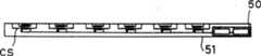
作为第五实施例,将参考图7到9地,描述能应用于第一至第四实施例的功率输送组件51。图7和8分别是功率输送组件51的平面图和剖视图,以及图9是表示易曲性的透视图。如图7所示,当设置方向“a”和“b”时,在图7和8所示的功率输送组件51上提供沿方向“a”的三个输送侧线圈CS乘以沿方向“b”的六个输送侧线圈CS,总共18个输送侧线圈CS。18个输送侧线圈CS之间的相关关系如同图1中输送侧线圈CS1、CS2和CS3中一样。如图8所示,功率输送组件51具有在垂直于设有输送侧线圈CS的平面的方向中很薄的薄片形状。As a fifth embodiment, a
功率输送组件51与第一实施例中的功率输送组件1(图1)、第二实施例中的功率输送组件21(图4)、第三实施例中的功率输送组件31(图5)以及第四实施例中的功率输送组件41(图6)类似,除输送侧线圈的形状和数量外。功率输送组件51的其他结构和操作与功率输送组件1、21、31和41类似。The
图7和8中的部分50表示除在功率输送组件51的部件中的输送侧线圈CS外,还提供一些部件(诸如图1中的输送侧开关SS1)。尽管在图7和8中示出了传输端线圈CS和除传输端线圈CS外的部件部分彼此分开的结构,如果不阻止功率输送组件51以薄片形状形成,那么除输送侧线圈CS外的部件可以位于接近输送侧线圈CS的区域中。
作为放置功率输送组件51的电子电路的板,采用通过使用聚酰亚胺薄膜等形成的柔性板等等,以及还通过使用具有易曲性的树脂等等构成功率输送组件51的外壳。通过这种结构,整个功率输送组件51具有易曲性,以及如图9所示,能弯曲功率输送组件51。因此,功率输送组件51不仅能设置于或粘附到平面上而且可沿具有曲面或三维形状的物体的形状设置或粘附。因此,通过将功率输送组件51设置或粘附到例如由不是特殊材料制成的杯状容器、矩形盒等等上,就可构成功率输送机。因此,功率输送机位于很小的空间中以及能节省放置功率输送机的空间。由于能构成任何形状的功率输送机,能构成适合用户需求诸如“便携性”、“当不使用时易于安置”等等的功率输送机,以及提高用于用户的可用性。As a board on which the electronic circuit of the
尽管在上述说明中,输送侧线圈CS的数量为18,很显然,它可以是任意多个数。Although in the above description, the number of delivery-side coils CS is 18, it is obvious that it may be any number.
第六实施例Sixth embodiment
在第六实施例中,将描述能应用于第一至第四实施例的功率接收组件(例如第一实施例中的功率接收组件2)。在第五实施例中,注意仅仅集中在功率输送组件51上并且已经描述过呈片状的具有易曲性的功率输送组件51。类似地,可以构成片状具有易曲性的功率接收组件52(未示出)并应用于第一至第四实施例。具体来说,通过用功率接收组件52代替功率输送组件51以及用接收侧线圈CJ(未示出)代替输送侧线圈CS,能构成片状具有易曲性的功率接收组件52。In the sixth embodiment, a power receiving assembly (such as the
功率接收组件52与第一实施例中的功率接收组件2(图1)、第二实施例中的功率接收组件22(图4)、第三实施例中的功率接收组件32(图5)和第四实施例中的功率接收组件42(图6)类似,除接收侧线圈的形状和数量外。功率接收组件52的其他结构和操作与功率接收组件2、22、32或42类似。因此,具有功率输送组件51和功率接收组件52的供电系统的操作类似于图2或3的流程图中所示。The power receiving component 52 and the power receiving component 2 ( FIG. 1 ) in the first embodiment, the power receiving component 22 ( FIG. 4 ) in the second embodiment, the power receiving component 32 ( FIG. 5 ) in the third embodiment and The power receiving assembly 42 (FIG. 6) in the fourth embodiment is similar except for the shape and number of coils on the receiving side. Other structures and operations of the power receiving assembly 52 are similar to those of the
通过将功率接收组件形成为具有薄片形状和易曲性,不仅能将功率接收组件52放置或粘附到平面上,而且沿具有曲面或三维形状的功率接收机的形状设置或粘附。由此,能构成不由功率接收机的形状限定的供电系统。特别地,仅通过随机地将粘附功率接收组件52的功率接收机放置在功率输送组件51上或附近,根据功率输送组件51和功率接收组件52间的位置关系,能执行最佳供电,以便增加功率接收机和功率输送机的布局的灵活性以及减轻对供电系统的用户的空间约束。很显然,可以将功率接收组件52粘附到功率接收机上以便局部或整个覆盖功率接收机。By forming the power receiving assembly to have a sheet shape and flexibility, it is possible to place or adhere the power receiving assembly 52 not only on a flat surface but also along the shape of a power receiver having a curved surface or a three-dimensional shape. Accordingly, it is possible to configure a power supply system not limited by the shape of the power receiver. In particular, only by randomly placing the power receivers adhering the power receiving unit 52 on or near the
第七实施例Seventh embodiment
在第七实施例中,通过参考图10来描述通过组合第五和第六实施例获得的供电系统。图10是表示应用第七实施例的供电系统的例子的示意图。功率输送盒70是具有矩形平行六面体形状的空盒并且输送盒70的一个表面是打开的。将与在第五实施例中的所述的功率输送组件51相同的“具有薄片状和易曲性的功率输送组件71”沿功率输送盒70的内部形状设置或粘附。In the seventh embodiment, a power supply system obtained by combining the fifth and sixth embodiments is described by referring to FIG. 10 . Fig. 10 is a schematic diagram showing an example of a power supply system to which the seventh embodiment is applied. The
功率输送组件71具有总共六个输送侧线圈CS1至CS6。在图10中,省略除功率输送组件71中的输送侧线圈CS1至CS6外的部件(诸如图1中的输送侧开关SS1),但以与图1中的功率输送组件1类似的方式,功率输送组件71具有除输送侧线圈CS1至CS6外的部件。功率输送组件71与第五实施例中的功率输送组件51类似,除输送侧线圈的形状和数量外。功率输送组件71的其他结构和操作与功率输送组件51类似。The
功率输送组件71可以埋入功率输送盒70中。很显然,可以将功率输送组件71放置、粘附或全部或部分埋在功率输送盒70的里面上/内。在这种情况下,能将功率输送组件71和功率输送盒70的组合看作这一实施例的供电系统中的功率输送机。The
功率输送盒70的形状不限于矩形平行六面体形,而是可以是任何形状,诸如具有曲面的杯状,只要能容纳或放置功率接收机。对功率输送组件71,连接具有能连接到AC插座的AC插头的电源绳74。提供到电源绳74的商业电源是用于使功率接收机73充电的电源,这将在下面描述。The shape of the
对功率接收机73,将如同在第六实施例中所述的功率接收组件52的“具有薄片状和易曲性的功率接收组件72”放置或粘附成沿功率接收机73的形状,以及经功率接收组件72,能充电功率接收机73,如在其他实施例中所述。功率接收组件72具有总共六个接收侧线圈CJ1至CJ6。在图10中,省略除接收侧线圈CJ1至CJ6外的部件(例如图1中的接收侧开关SJ1)。然而,与图1中的功率接收组件2一样,功率接收组件72具有除接收侧线圈CJ1至CJ6外的部件。For the
功率接收组件72与第六实施例中的功率接收组件52类似,除接收侧线圈的形状和数量外,以及其他结构和操作与功率接收组件52类似。因此,具有功率输送组件71和功率接收组件72的供电系统的操作类似于图2或3的流程图中所示。The
作为通过它,功率接收机73从功率接收组件72接收电源的装置,功率接收机73和功率接收组件72可以彼此电气连接。另外,将功率接收组件72设置成初级端,功率接收机73设置成次级端,可以通过磁耦合,以非接触方式供电。在充电功率接收机时,可以将功率接收组件72连接到功率接收机73。另外,可以将预先设置功率接收组件72在功率接收机73的内部。As means through which the
图10表示将连接功率接收组件72的功率接收机73容纳在连接功率输送组件71的功率输送盒70中的情形。在这种情况下,在输送侧线圈CS1至CS6和接收侧线圈CJ1至CJ6的组合中,输送侧线圈CS1和接收侧线圈CJ5间的距离最短。FIG. 10 shows a state where a
因此,当实施图2或3的供电系统的操作中的功率供应等级测试时,确定输送侧线圈CS1和接收侧线圈CJ5的组合实现最大功率输送效率(图2或3的步骤#11)。由此,在输送侧线圈CS1和接收侧线圈CJ5间开始供电(见图2或3中的步骤#13)。Therefore, when conducting the power supply level test in operation of the power supply system of FIG. 2 or 3 , it is determined that the combination of the transmission side coil CS1 and the reception side coil CJ5 achieves the maximum power transfer efficiency (
如上所述,仅通过将如连接功率接收组件72的功率接收机73的功率接收机放置在容器,诸如功率输送组件71部分或全部粘附或埋在其上/里的功率输送盒70中,而不注意容器和功率接收机(在图10中,功率输送盒70和功率接收机73)间的位置关系,可以自动识别和选择位置关系最佳的最高功率输送效率的输送侧线圈CS1至CS6的任何一个和接收侧线圈CJ1至CJ6的任何一个间的组合,以及使功率接收机充电。通过这种结构,减轻空间约束以及显著地提高用户的可用性。从本发明的结构看,容器(功率输送盒70)的材料不限于特殊材料,诸如磁性材料,而可以是纸或树脂,诸如聚碳酸脂是很显然的。As described above, simply by placing the power receiver, such as the
如上所述,功率输送盒70具有其一个面是打开的盒形状。可以在打开面上提供可打开/关闭或可拆卸的盖。在具有打开或拆卸盖的情况下,可以插入或取出功率接收机,诸如功率接收机73。当关闭或连接盖时,从外部空间密封地关闭或关闭功率输送盒70的内部空间。可以用导体,诸如金属片全部或部分覆盖或屏蔽加盖的功率输送盒70。代替用导体覆盖输送盒70,可以将功率输送盒70本身形成为由金属等等制成的导体。As described above, the
通过这种结构,可减少供电时的电磁噪声和泄漏到功率输送盒70的外部的不必要的辐射,以及能减少由于电子设备上的电磁噪声等等对功率输送盒70的外部的不利影响。当将具有功率输送组件71的功率输送盒70看作专用于充电的容器时,加盖不降低用户可用性。With this configuration, electromagnetic noise during power supply and unnecessary radiation leaking to the outside of the
在制造供电系统时或通过供电系统的用户,还可以对多个功率接收组件72指定不同标识符号,以及通过使用“用于传送指令信号S的装置”,将标识符号传送到功率输送组件71,如第一至第四实施例中所述。通过这种结构,在将每个连接功率接收组件72的多个功率接收机73容纳在功率输送盒70中的情况下,功率输送组件71能在标识符号的基础上,识别出多个功率接收机73容纳在功率输送盒70中(未示出)。When manufacturing the power supply system or by the user of the power supply system, it is also possible to assign different identification symbols to a plurality of
如图2或3所示,功率接收组件72和功率输送组件71的每一个单独地执行操作,从而确定最高功率输送效率的输送侧线圈CS1至CS6的任何一个和接收侧线圈CJ1至CJ6的任何一个的组合,以及最佳地同时将功率提供到这些功率接收组件72。如上所述,通过将每个连接功率接收组件72的多个功率接收机73容纳在连接功率输送组件71的功率输送盒70中,可最佳地同时将功率提供到各功率接收机73。As shown in FIG. 2 or 3 , each of the
第八实施例Eighth embodiment
在第八实施中,将描述能应用于上述第一至第七实施例的任何一个的供电系统。通过采用图10的结构作为例子来描述第八实施例。通过参考图2和3,如上所述执行供电系统的操作,从而根据连接功率输送组件71的功率输送盒70和连接功率接收组件72的功率接收机73间的位置关系,通过最高功率输送效率的输送侧线圈CS1至CS6的任何一个和接收侧线圈CJ1至CJ6的任何一个的组合,执行通过磁耦合的非接触供电。In an eighth implementation, a power supply system applicable to any one of the first to seventh embodiments described above will be described. The eighth embodiment is described by taking the structure of FIG. 10 as an example. By referring to FIGS. 2 and 3 , the operation of the power supply system is performed as described above so that, according to the positional relationship between the
在第八实施例中,提供了用于将功率输送效率告知本发明的供电系统的用户的通知设备(未示出)。由例如由LED(发光二极管)等等形成的功率水平表、数值显示器、用于通过声音告知用户的扬声器、用于输出电信号的终端等等构成通知设备。除上述功率水平表等等外,还可以采用任何设备,只要它能告知用户功率输送效率即可。In an eighth embodiment, there is provided a notification device (not shown) for informing a user of the power supply system of the present invention of the power transmission efficiency. The notification device is constituted by, for example, a power level meter formed of LED (Light Emitting Diode) or the like, a numerical display, a speaker for notifying the user by sound, a terminal for outputting an electric signal, and the like. In addition to the above-mentioned power level meter and the like, any device may be used as long as it informs the user of the power delivery efficiency.
提供用于功率输送组件71或功率接收组件72的通知设备(未示出)就足够了。可以在预先提供功率接收组件72的功率接收机73上提供通知设备(未示出),或则可以在粘附功率输送组件71的功率输送盒70上提供。在任何一种情况下,在功率输送组件的部件的任何一个中提供通知设备(未示出)就足够了。It is sufficient to provide a notification device (not shown) for the
通过该结构,在实际供电的情况下,用户能识别出功率输送效率。当用户希望较高功率输送效率时,用户能改变连接/提供功率接收组件72的功率接收机73和连接功率输送组件71的功率输送盒70间的位置关系以便获得较高功率输送效率。因此,提高功率输送效率,能在更短时间内使功率接收机73充电,以及还有利于节能。With this structure, in the case of actual power supply, the user can recognize the power transmission efficiency. When the user desires higher power transfer efficiency, the user can change the positional relationship between the
第九实施例Ninth embodiment
在第九实施例中,将描述能应用于上述第一至第八实施例的任何一个的供电系统。通过采用图10的结构作为例子来描述第九实施例。在第九实施例中,在图10的结构例子中,在功率输送组件71或功率接收组件72上提供作为输入设备的“供电电平测试重启按钮”(未示出)。供电电平测试重启按钮是能在任何时间,由用户接通或断开的按钮。在本发明的供电系统中,通过在供电期间接通/断开供电电平测试重启按钮,供电系统从步骤#1重启图2或3中所示的操作。In a ninth embodiment, a power supply system applicable to any one of the first to eighth embodiments described above will be described. The ninth embodiment is described by taking the structure of FIG. 10 as an example. In the ninth embodiment, in the structural example of FIG. 10 , a "power supply level test restart button" (not shown) is provided as an input device on the
在步骤#2至#10中的处理后,判定电路7确定目前最高功率输送效率的输送侧线圈CS1至CS6的任何一个和接收侧线圈CJ1至CJ6的任何一个的组合(见图2或3中的步骤#11)以及将根据确定结果的指令信号S传送到输送侧开关切换电路(输送侧开关切换电路3或33)以及接收侧开关切换电路(接收侧开关切换电路5)(见图2或3中的步骤#12)。因此,通过目前最高功率输送效率的输送侧线圈CS1至CS6的任何一个和接收侧线圈CJ1至CJ6的任何一个间的组合,重启供电。After the processing in
可以在预先提供功率接收组件72的功率接收机73上提供供电电平测试重启按钮,或可以在粘附功率输送组件71的功率输送盒70上提供。可以在供电系统的任何一个部件上提供供电电平测试重启按钮。作为输入设备的供电电平测试重启按钮不必具有按钮形状,而是可以采用任何输入装置,诸如开关、外部输入端子等等,只要本发明的供电系统的用户能将信号提供到供电系统即可。A supply level test reset button may be provided on the
例如,会存在在供电期间,由于一些偶然或人为造成的故障,改变功率输送组件71和功率接收组件72间的相对位置以及用于实际输送/接收功率的输送侧线圈CS1到地CS6的任何一个和接收侧线圈CJ1至CJ6的任何一个间的组合变得不是最佳,诸如不能供电的情形的情形。For example, during the power supply, due to some accidental or man-made faults, the relative position between the
在这种情况下,用户接通或断开供电电平测试重启按钮,从而重新确定在这种状态下输送侧线圈CS1到CS6的任何一个和接收侧线圈CJ1至CJ6的任何一个间的最佳组合以及在所确定的组合中重启最佳供电。即,重启最佳供电。如第八实施例中所述,用户还能在从通知设备(未示出)发送的功率输送效率的通知的基础上,确定是否接通或断开供电电平测试重启按钮。如上所述,第九实施例能与第一至第八实施例的任何一个结合。例如,在将第九实施例与第一实施例结合的情况下,可在功率输送组件1、功率接收组件2(见图1)等等上设置供电电平测试重启按钮。In this case, the user turns on or off the power supply level test reset button, thereby re-determining the optimum voltage between any one of the transmission-side coils CS1 to CS6 and any one of the reception-side coils CJ1 to CJ6 in this state. combination and restart the best power supply in the determined combination. That is, the optimal power supply is restarted. As described in the eighth embodiment, the user can also determine whether to turn on or off the power supply level test reset button on the basis of the notification of the power transmission efficiency sent from the notification device (not shown). As described above, the ninth embodiment can be combined with any one of the first to eighth embodiments. For example, in the case of combining the ninth embodiment with the first embodiment, a power supply level test reset button can be provided on the
第十实施例Tenth embodiment
在第十实施例中,将描述能应用于第一至第九实施例的任何一个的供电系统。通过使用图10的结构作为例子来描述第十实施例。在第十实施例中,在图10所示的结构例子中,在供电期间的所有时间或以预定间隔测量实际输送/接收功率的输送侧线圈CS1至CS6和接收侧线圈CJ1至CJ6的组合中的功率输送效率。当功率输送效率变得等于或低于预定效率的状态持续预定时间或更长时,用与在第九实施例中接通或断开供电电平测试重启按钮类似的方式,图2或3所示的操作从步骤#1自动开始。In the tenth embodiment, a power supply system applicable to any one of the first to ninth embodiments will be described. The tenth embodiment is described by using the structure of FIG. 10 as an example. In the tenth embodiment, in the configuration example shown in FIG. 10 , in the combination of the transmission-side coils CS1 to CS6 and the reception-side coils CJ1 to CJ6 that measure actual transmitted/received power at all times during power supply or at predetermined intervals power transfer efficiency. When the state in which the power transmission efficiency becomes equal to or lower than the predetermined efficiency continues for a predetermined time or longer, in a manner similar to turning on or off the power supply level test restart button in the ninth embodiment, shown in FIG. 2 or 3 The operation shown starts automatically from
在步骤#2至#10的处理后,判定电路7确定目前最高功率输送效率的输送侧线圈CS1至CS6的任何一个和接收侧线圈CJ1至CJ6的任何一个间的组合(见图2或3的步骤#11)以及将根据确定结果的指令信号S传送到输送侧开关切换电路(输送侧开关切换电路3或33)以及接收侧开关切换电路(接收侧开关切换电路5)(见图2或3中的步骤#12)。因此,通过目前最高功率输送效率的输送侧线圈CS1至CS6的任何一个和接收侧线圈CJ1至CJ6的任何一个间的组合,重启供电。After the processing of
通过这种结构,即使出现由于一些偶然或人为造成的故障,功率输送组件71和功率接收组件72间的相对位置改变,不能供电,以及用于实际输送/接收的输送侧线圈CS1至CS6的任何一个和接收侧线圈CJ1至CJ6的任何一个间的组合变得不是最佳的情形,能再次自动选择输送侧线圈CS1至CS6的任何一个和接收侧线圈CJ1至CJ6的任何一个间的最佳组合以及重启最佳供电,而在供电期间不必关注功率输送效率。预定效率和预定时间可以是固定值或可以在本发明的供电系统上提供用户能经常设定那些值的装置。With this structure, even if some accidental or artificial failure occurs, the relative position between the
第十实施例能与第一至第九实施例的任何一个结合。例如,在将第十实施例与第一实施例结合的情况下,假定输送侧线圈CS1至CS3对应于输送侧线圈CS1到CS6以及接收侧线圈CJ1至CJ3对应于接收侧线圈CJ1至CJ6则足以。The tenth embodiment can be combined with any one of the first to ninth embodiments. For example, in the case of combining the tenth embodiment with the first embodiment, it is sufficient to assume that the transmission-side coils CS1 to CS3 correspond to the transmission-side coils CS1 to CS6 and the reception-side coils CJ1 to CJ3 correspond to the reception-side coils CJ1 to CJ6 .
第十一实施例Eleventh embodiment
在图1的结构例子中,可以根据每个功率接收机的所需功率(未示出),改变输送侧线圈CS1、CS2和CS3的输送功率。通过关注图1中的输送侧线圈CS1,描述改变输送功率的方法(第十一实施例)。In the configuration example of FIG. 1, the transmission power of the transmission side coils CS1, CS2, and CS3 can be changed according to the required power (not shown) of each power receiver. A method of changing the transmission power (eleventh embodiment) will be described by focusing on the transmission-side coil CS1 in FIG. 1 .
在图1所示的结构中,当接通输送侧开关SS1时,将施加在电压输入端8和9间的电压Vin施加到输送侧线圈CS1的整个线圈部分上。在输送侧线圈CS1上提供分接头A(未示出)以及除输送侧开关SS1外,还在电压输入端8和分接头A间串联提供开关A(未示出)以便能在分接头A和电压输入端9两端施加电压Vin。输送侧开关切换电路3将用于接通/断开开关A和输送侧开关SS1的信号独立地提供给开关A和和输送侧开关SS1。In the configuration shown in FIG. 1, when the transmission side switch SS1 is turned on, the voltage Vin applied between the
在断开输送侧开关SS1和接通开关A的情况下,将电压Vin施加到输送侧线圈CS1的线圈部分中分接头A和电压输入端9间的线圈部分上。因此,与接通输送侧开关SS1和断开开关A以便将电压Vin施加到输送侧线圈CS1的整个线圈部分上的情形相比,输送功率变得更小。With the supply-side switch SS1 turned off and the switch A turned on, the voltage Vin is applied to the coil portion between the tap A and the
尽管上面描述了在输送侧线圈CS1上仅提供一个分接头的情形,在以三个等级切换输送功率的情况下,提供两个分接头则足够。类似地,能提供以所需切换输送功率的功能。输送侧线圈CS2和CS3能类似地构成并能独立地切换输送功率。作为开关A,能使用晶体管、继电器开关等等。能将这一切换输送功率的方法应用于第一至第十实施例的任何一个。Although the above describes the case where only one tap is provided on the transmission-side coil CS1, in the case of switching the transmission power at three levels, it is sufficient to provide two taps. Similarly, the ability to switch delivery power as desired can be provided. The transmission side coils CS2 and CS3 can be similarly constituted and can switch transmission power independently. As the switch A, a transistor, a relay switch, or the like can be used. This method of switching transmission power can be applied to any of the first to tenth embodiments.
如上所述,通过提供能切换多个输送侧线圈CS1、CS2和CS3的每一个的输送功率的装置,根据不同类型的功率接收机和其所需供电彼此不同,能最佳地供电。通过使用输送侧线圈CS1、CS2和CS3以及接收侧线圈CJ1、CJ2和CJ3间的磁耦合,或通过使用如在第二实施例中所示的专用信号传送线圈CIJ以及专用信号接收线圈CIS,能传送将充电的功率接收机的所需功率的信息。另外,通过使用如在第三和第四实施例中所述的用于传送指令信号S的装置,可以传送信息。As described above, by providing means capable of switching the transmission power of each of the plurality of transmission side coils CS1, CS2 and CS3, power supply can be optimally supplied according to different types of power receivers and their required power supply differing from each other. By using magnetic coupling between the transmission-side coils CS1, CS2, and CS3 and the reception-side coils CJ1, CJ2, and CJ3, or by using the dedicated signal transmission coil CIJ and the dedicated signal reception coil CIS as shown in the second embodiment, it is possible to Information about the required power of the power receiver to be charged is transmitted. In addition, by using the means for transmitting the command signal S as described in the third and fourth embodiments, information can be transmitted.
第十二实施例Twelfth embodiment
在第十二实施例中,将参考图11来描述能应用于第一至第十一实施例的供电系统。图11是供电系统的示意图。通过将图10中的功率输送盒70和功率输送组件71组合获得功率输送盒80。供电软线84类似于图10所示之供电软线74。将与在第一至第十一实施例的每一个中类似的功率接收组件(诸如图10中的功率接收组件72,在下文中,称为“功率接收组件72”)连接到或在容纳在功率输送盒80中的功率接收机85至88的每一个中提供。假定功率接收机85至88的所需功率彼此不同。In the twelfth embodiment, a power supply system applicable to the first to eleventh embodiments will be described with reference to FIG. 11 . Fig. 11 is a schematic diagram of the power supply system. The
在连接到功率接收机85的功率接收组件72和功率输送组件71间,执行与图2和3中类似的操作。连接到功率接收机85的功率接收组件72的判定电路7将指令信号S传送到功率输送组件71的输送侧开关切换电路(输送侧开关切换电路3或33)以及连接到功率接收机85的功率接收组件72的接收侧开关切换电路(接收侧开关切换电路5)。通过这一结构,通过最高功率输送效率的输送侧线圈CS1至CS6的任何一个与(在连接到功率接收机85的功率接收组件72上提供的)接收侧线圈CJ1至CJ6的任何一个间的组合,向功率接收机85供电。Between the
类似地,在连接到功率接收机86、87和88的功率接收组件72的每一个和功率输送组件71之间,执行与在图2和3中所示的类似的操作。以用于功率接收机86、87和88的每一个的最高功率输送效率的输送侧线圈CS1至CS6的任何一个和(在连接到功率接收机86、87和88的每一个上的功率接收组件72上提供的)接收侧线圈CJ1至CJ6的任何一个间的组合,提供功率。Similarly, between each of the
由于功率接收机85至88的所需功率彼此不同,理想地,用于传送功率的功率输送盒80将所需功率输送到功率接收机85至88的每一个。因此,应用在第十一实施例中的结构,同时通过图2或3中所示的操作,选择功率接收机85至88的每一个的接收侧线圈(未示出)和功率输送盒80的输送侧线圈(未示出)间的最佳组合,对功率接收机85至88的每一个,切换传送到功率接收机85到88的每一个的功率。Since the required power of the
因此,用户随意将连接到本发明的功率接收组件(例如功率接收组件72)或在其中设置的移动电话、笔记本型个人计算机、数字照相机、电动剃须刀、电子玩具等等的功率接收机放置或摆放到功率输送盒80中,而不关心功率接收机和功率输送盒80间的位置关系,从而即使功率接收机的所需功率彼此不同,也可自动地执行同时最佳充电。Therefore, the user arbitrarily places a power receiver connected to the power receiving unit (such as the power receiving unit 72) of the present invention or a mobile phone, a notebook personal computer, a digital camera, an electric shaver, an electronic toy, etc. set therein. Or placed into the
通过结合第一至第十二实施例,能构成供电系统,只要没有矛盾出现。具有功率输送组件1、21、31、41、51和71的任何一个和功率接收组件2、22、32、42和72的任何一个的供电系统的操作与图2和3所示的类似。By combining the first to twelfth embodiments, a power supply system can be constituted as long as no contradiction arises. The operation of the power supply system having any one of the
“在功率接收机中提供功率接收组件”相当于“将功率接收组件连接到功率接收机的内部”。因此,“在功率接收机中提供功率接收组件”是包括在“将功率接收组件连接到功率接收机”中的的概念。"Providing the power receiving component in the power receiver" is equivalent to "connecting the power receiving component to the inside of the power receiver". Therefore, 'providing a power receiving component in a power receiver' is a concept included in 'connecting a power receiving component to a power receiver'.
Claims (16)
Translated fromChineseApplications Claiming Priority (2)
| Application Number | Priority Date | Filing Date | Title |
|---|---|---|---|
| JP2003339935AJP4036813B2 (en) | 2003-09-30 | 2003-09-30 | Non-contact power supply system |
| JP2003339935 | 2003-09-30 |
Publications (2)
| Publication Number | Publication Date |
|---|---|
| CN1604437A CN1604437A (en) | 2005-04-06 |
| CN1298097Ctrue CN1298097C (en) | 2007-01-31 |
Family
ID=34373376
Family Applications (1)
| Application Number | Title | Priority Date | Filing Date |
|---|---|---|---|
| CNB2004100834527AExpired - Fee RelatedCN1298097C (en) | 2003-09-30 | 2004-09-30 | Non-contact power supply system |
Country Status (3)
| Country | Link |
|---|---|
| US (1) | US7450910B2 (en) |
| JP (1) | JP4036813B2 (en) |
| CN (1) | CN1298097C (en) |
Cited By (5)
| Publication number | Priority date | Publication date | Assignee | Title |
|---|---|---|---|---|
| TWI466405B (en)* | 2007-12-20 | 2014-12-21 | Gen Electric | Contactless power and data transfer system and method |
| CN105305533A (en)* | 2014-07-23 | 2016-02-03 | 威斯通全球技术公司 | Selecting a configuration of coils in response to a multi-coil wireless charging system initiating charging |
| CN106026245A (en)* | 2010-02-12 | 2016-10-12 | 株式会社半导体能源研究所 | Vehicle |
| CN108233550A (en)* | 2018-02-01 | 2018-06-29 | 上海电机学院 | A kind of multistage multi-panel magnetic resonance pacemaker wireless charging system |
| CN109599954A (en)* | 2018-12-19 | 2019-04-09 | 北京航空航天大学 | Radio transmission method, wireless transmission component and endoscope apparatus |
Families Citing this family (127)
| Publication number | Priority date | Publication date | Assignee | Title |
|---|---|---|---|---|
| WO2005096485A1 (en)* | 2004-03-30 | 2005-10-13 | Daifuku Co., Ltd. | Noncontact power supply facility |
| JP2006314181A (en)* | 2005-05-09 | 2006-11-16 | Sony Corp | Non-contact charger, non-contact charging system, and non-contact charging method |
| AU2006318721A1 (en)* | 2005-11-21 | 2007-05-31 | Powercast Corporation | Radio-frequency (RF) power portal |
| KR100792308B1 (en)* | 2006-01-31 | 2008-01-07 | 엘에스전선 주식회사 | Solid state charging device with coil array, solid state charging system and charging method |
| CN100375370C (en)* | 2006-03-03 | 2008-03-12 | 重庆大学 | Zone-controlled power strips |
| JP2009545876A (en)* | 2006-08-04 | 2009-12-24 | エスケー ケミカルズ カンパニー リミテッド | Induction coil for non-contact energy charging and data transmission |
| US9022293B2 (en)* | 2006-08-31 | 2015-05-05 | Semiconductor Energy Laboratory Co., Ltd. | Semiconductor device and power receiving device |
| JP4308855B2 (en)* | 2007-01-17 | 2009-08-05 | セイコーエプソン株式会社 | Power reception control device, power reception device, and electronic device |
| JP4413236B2 (en)* | 2007-02-16 | 2010-02-10 | セイコーエプソン株式会社 | Power reception control device, power transmission control device, non-contact power transmission system, power reception device, power transmission device, and electronic device |
| US8588681B2 (en)* | 2007-02-23 | 2013-11-19 | Nec Corporation | Semiconductor device performing signal transmission by using inductor coupling |
| FR2920061A1 (en)* | 2007-08-17 | 2009-02-20 | Patrick Camurati | METHOD AND DEVICE FOR TRANSPORTING, DISTRIBUTING AND MANAGING ELECTRICAL ENERGY BY LONGITUDINAL COUPLING IN A CLOSE FIELD BETWEEN ELECTRIC DIPOLES |
| GB0716679D0 (en) | 2007-08-28 | 2007-10-03 | Fells J | Inductive power supply |
| CA2701394A1 (en)* | 2007-10-17 | 2009-04-23 | Access Business Group International Llc | Laptop and portable electronic device wireless power supply systems |
| KR100976161B1 (en)* | 2008-02-20 | 2010-08-16 | 정춘길 | Contactless charging system and its charging control method |
| US8228026B2 (en) | 2008-02-25 | 2012-07-24 | L & P Property Management Company | Inductively coupled shelving and storage containers |
| US8421407B2 (en)* | 2008-02-25 | 2013-04-16 | L & P Property Management Company | Inductively coupled work surfaces |
| JP2009201328A (en)* | 2008-02-25 | 2009-09-03 | Toshiba Corp | Charger and charging system |
| US8855554B2 (en) | 2008-03-05 | 2014-10-07 | Qualcomm Incorporated | Packaging and details of a wireless power device |
| US8338990B2 (en) | 2008-03-13 | 2012-12-25 | Access Business Group International Llc | Inductive power supply system with multiple coil primary |
| WO2009116137A1 (en)* | 2008-03-18 | 2009-09-24 | パイオニア株式会社 | Display driving device and display device |
| EP2277252A4 (en) | 2008-04-21 | 2017-04-26 | Qualcomm Incorporated | Short range efficient wireless power transfer |
| US20090284369A1 (en) | 2008-05-13 | 2009-11-19 | Qualcomm Incorporated | Transmit power control for a wireless charging system |
| US7893564B2 (en)* | 2008-08-05 | 2011-02-22 | Broadcom Corporation | Phased array wireless resonant power delivery system |
| JP4743244B2 (en)* | 2008-09-18 | 2011-08-10 | トヨタ自動車株式会社 | Non-contact power receiving device |
| EP2345552B1 (en) | 2008-10-09 | 2019-11-20 | Toyota Jidosha Kabushiki Kaisha | Electrical powered vehicle |
| US9178376B2 (en) | 2008-12-12 | 2015-11-03 | Hanrim Postech Co., Ltd. | Non-contact charging station with power transmission planar spiral core, non-contact power-receiving apparatus, and method for controlling the same |
| US9130395B2 (en) | 2008-12-12 | 2015-09-08 | Hanrim Postech Co., Ltd. | Non-contact charging station with planar spiral power transmission coil and method for controlling the same |
| CN101764435B (en)* | 2008-12-22 | 2014-09-10 | 爱信艾达株式会社 | Power reception guidance device |
| CN102077438A (en)* | 2009-01-05 | 2011-05-25 | L&P产权管理公司 | Inductively coupled consoles |
| JP5467569B2 (en)* | 2009-01-21 | 2014-04-09 | 国立大学法人埼玉大学 | Non-contact power feeding device |
| US8497658B2 (en) | 2009-01-22 | 2013-07-30 | Qualcomm Incorporated | Adaptive power control for wireless charging of devices |
| JP2010183812A (en)* | 2009-02-09 | 2010-08-19 | Toyota Industries Corp | Resonant contactless charging system |
| US20100201312A1 (en) | 2009-02-10 | 2010-08-12 | Qualcomm Incorporated | Wireless power transfer for portable enclosures |
| US9312924B2 (en)* | 2009-02-10 | 2016-04-12 | Qualcomm Incorporated | Systems and methods relating to multi-dimensional wireless charging |
| AU2010213557A1 (en)* | 2009-02-13 | 2011-09-01 | Witricity Corporation | Wireless energy transfer in lossy environments |
| JP5173901B2 (en)* | 2009-03-13 | 2013-04-03 | 三菱電機株式会社 | Contactless power supply / reception device |
| JP5347619B2 (en)* | 2009-03-24 | 2013-11-20 | 日産自動車株式会社 | Non-contact power feeding device and electric vehicle |
| JP5597022B2 (en)* | 2009-05-13 | 2014-10-01 | キヤノン株式会社 | Power supply apparatus and control method |
| JP5603647B2 (en) | 2009-05-13 | 2014-10-08 | キヤノン株式会社 | Power feeding device, power feeding device control method, and power feeding communication system |
| JP5446452B2 (en) | 2009-05-21 | 2014-03-19 | ソニー株式会社 | POWER SUPPLY DEVICE, POWERED SUPPLY DEVICE, POWER SUPPLY DEVICE SYSTEM, AND POSITIONING CONTROL METHOD |
| JP5107309B2 (en)* | 2009-06-25 | 2012-12-26 | グローブライド株式会社 | Fishing charger |
| JP5499534B2 (en)* | 2009-07-07 | 2014-05-21 | ソニー株式会社 | Non-contact power receiving apparatus, power receiving method in non-contact power receiving apparatus, and non-contact power feeding system |
| WO2011077488A1 (en)* | 2009-12-24 | 2011-06-30 | 株式会社 東芝 | Wireless power transmission apparatus |
| KR101688875B1 (en)* | 2010-03-31 | 2016-12-26 | 삼성전자주식회사 | Wireless recharging set |
| CN102823109B (en)* | 2010-04-13 | 2015-01-28 | 富士通株式会社 | Power supply system, power transmitter, and power receiver |
| JP2011229314A (en)* | 2010-04-21 | 2011-11-10 | Sanyo Electric Co Ltd | Charging device, and, method of controlling charging device |
| JP5527407B2 (en)* | 2010-04-30 | 2014-06-18 | 富士通株式会社 | Wireless power receiving apparatus and power receiving method |
| JP5593926B2 (en)* | 2010-07-29 | 2014-09-24 | ソニー株式会社 | Power feeding system, power feeding device and electronic device |
| JP2012044827A (en)* | 2010-08-23 | 2012-03-01 | Midori Anzen Co Ltd | Non-contact charger |
| NZ588159A (en)* | 2010-09-23 | 2014-01-31 | Powerbyproxi Ltd | A contactless power transfer system |
| CN101969236A (en)* | 2010-09-29 | 2011-02-09 | 上海海事大学 | Electric non-contact power supply mobile connecting device |
| JP5659718B2 (en)* | 2010-11-11 | 2015-01-28 | ソニー株式会社 | Transmission device and electronic device |
| JP2012105478A (en)* | 2010-11-11 | 2012-05-31 | Sony Corp | Transmission device, electronic equipment, and transmission method |
| CN102610379A (en)* | 2011-01-25 | 2012-07-25 | 深圳市摩西尔电子有限公司 | Connector and signal transmission method |
| JP5838562B2 (en) | 2011-02-17 | 2016-01-06 | 富士通株式会社 | Wireless power transmission device and wireless power transmission system |
| CN102934327B (en)* | 2011-03-11 | 2015-11-25 | 海尔集团公司 | Wireless power supply device and method |
| CN102215002A (en)* | 2011-05-25 | 2011-10-12 | 姬志强 | Non-conductor contact electric energy transmission device |
| JP5810632B2 (en)* | 2011-05-27 | 2015-11-11 | 日産自動車株式会社 | Non-contact power feeding device |
| JP5790189B2 (en)* | 2011-06-16 | 2015-10-07 | 株式会社Ihi | Non-contact power feeding device |
| JP2013027074A (en)* | 2011-07-15 | 2013-02-04 | Panasonic Corp | Non-contact power supply device |
| JP6064337B2 (en) | 2011-08-10 | 2017-01-25 | ソニー株式会社 | Power feeding system, power feeding device and electronic device |
| JP6007561B2 (en) | 2011-10-21 | 2016-10-12 | ソニー株式会社 | Power supply device and power supply system |
| JP2013102665A (en) | 2011-10-21 | 2013-05-23 | Sony Corp | Power-feed device and power-feed system |
| JP6003172B2 (en) | 2011-10-21 | 2016-10-05 | ソニー株式会社 | Power supply device and power supply system |
| US9697952B2 (en)* | 2011-10-27 | 2017-07-04 | Toyota Jidosha Kabushiki Kaisha | Non-contact electric power reception device, non-contact electric power transmission device, and non-contact electric power transmission and reception system |
| JP5919991B2 (en) | 2011-11-29 | 2016-05-18 | ソニー株式会社 | Electronic device, power supply device and power supply system |
| JP6060516B2 (en) | 2011-11-30 | 2017-01-18 | ソニー株式会社 | Electronic equipment and power supply system |
| KR101943355B1 (en)* | 2011-12-05 | 2019-01-29 | 엘지전자 주식회사 | Mobile terminal |
| JP5857861B2 (en) | 2011-12-21 | 2016-02-10 | ソニー株式会社 | Power supply device, power supply system, and electronic device |
| JP5849842B2 (en) | 2011-12-21 | 2016-02-03 | ソニー株式会社 | Power supply device, power supply system, and electronic device |
| JP6060515B2 (en) | 2011-12-22 | 2017-01-18 | ソニー株式会社 | Electronic equipment and power supply system |
| JP6047911B2 (en) | 2011-12-22 | 2016-12-21 | ソニー株式会社 | Electronic equipment and power supply system |
| US9722451B2 (en) | 2012-01-27 | 2017-08-01 | Sony Corporation | Electronic unit and power feeding system |
| KR20130102218A (en)* | 2012-03-07 | 2013-09-17 | 엘에스전선 주식회사 | Wireless power receiving device with multi coil and wireless power receiving method |
| CN103368269A (en)* | 2012-03-28 | 2013-10-23 | 姬志强 | Intrinsic safe type roadway lamp protected by current limiting device |
| CN102611212A (en)* | 2012-03-28 | 2012-07-25 | 姬志强 | Non-conductor contact electric energy transmission method adopting split type switch transformer |
| JP5903990B2 (en)* | 2012-03-30 | 2016-04-13 | 株式会社デンソー | Contactless power supply |
| FR2989529B1 (en)* | 2012-04-12 | 2016-04-15 | Continental Automotive France | METHOD AND MAGNETIC COUPLING LOAD BENCH |
| JP2013243431A (en)* | 2012-05-17 | 2013-12-05 | Equos Research Co Ltd | Antenna coil |
| JP5948676B2 (en)* | 2012-05-18 | 2016-07-06 | パナソニックIpマネジメント株式会社 | Non-contact power supply system, non-contact power supply device, and power supplied device |
| DE102012013498B3 (en)* | 2012-07-06 | 2013-01-17 | Audi Ag | Device for inductive transmission of electrical energy from primary coil to secondary coil of e.g. motor vehicle, has solenoid coil pick-up portions of primary and secondary coils for adjusting coil length for inductive energy transfer |
| JP2014030288A (en) | 2012-07-31 | 2014-02-13 | Sony Corp | Power-feeding device and power-feeding system |
| JP5801268B2 (en)* | 2012-09-03 | 2015-10-28 | 株式会社東芝 | Power transmission device, power reception device, and wireless power transmission system |
| JP5836287B2 (en) | 2013-01-07 | 2015-12-24 | 東芝テック株式会社 | Power transmission equipment |
| TWI482389B (en)* | 2013-03-01 | 2015-04-21 | Luxx Lighting Technology Taiwan Ltd | Inductive power transfer system, and transmitter and receiver devices thereof |
| JP6323054B2 (en) | 2013-03-08 | 2018-05-16 | Tdk株式会社 | Power feeding device, power receiving device, and wireless power transmission device |
| JP6040899B2 (en)* | 2013-04-08 | 2016-12-07 | ソニー株式会社 | Electronic equipment and power supply system |
| JP6127668B2 (en) | 2013-04-08 | 2017-05-17 | ソニー株式会社 | Electronic equipment and power supply system |
| CN104143861A (en)* | 2013-05-09 | 2014-11-12 | 泰科电子(上海)有限公司 | Contactless power supply circuit |
| JP6145318B2 (en)* | 2013-05-31 | 2017-06-07 | 小島プレス工業株式会社 | Contactless power transmission equipment |
| JP5889250B2 (en)* | 2013-07-12 | 2016-03-22 | 東芝テック株式会社 | Power transmission device, power transmission device and power reception device for power transmission device |
| JP6361367B2 (en) | 2013-10-04 | 2018-07-25 | Tdk株式会社 | Power receiving device and power feeding device |
| KR20150052367A (en)* | 2013-10-10 | 2015-05-14 | 엘지이노텍 주식회사 | Wireless apparatus for transmitting power |
| WO2015064132A1 (en)* | 2013-10-30 | 2015-05-07 | 日本電気株式会社 | Power transmitting device, power receiving device, and wireless power transmission system |
| JP6141175B2 (en)* | 2013-11-12 | 2017-06-07 | 京セラ株式会社 | Electronics |
| CN103795157B (en)* | 2014-02-08 | 2016-03-23 | 北京智谷睿拓技术服务有限公司 | Wireless energy transfer method and wireless energy receiving equipment |
| US9620985B2 (en)* | 2014-04-01 | 2017-04-11 | Intel Corporation | Multi-coil wireless charging |
| JP6189786B2 (en) | 2014-04-25 | 2017-08-30 | ルネサスエレクトロニクス株式会社 | Power supply device and control method of power supply device |
| KR101771381B1 (en) | 2014-05-15 | 2017-08-24 | 닛산 지도우샤 가부시키가이샤 | Wireless power supply device |
| CN106464020A (en) | 2014-05-20 | 2017-02-22 | 富士通株式会社 | Wireless power transmission control method and wireless power transmission system |
| JP6375703B2 (en)* | 2014-06-06 | 2018-08-22 | 株式会社Ihi | Power transmission device and non-contact power feeding system |
| JP6308047B2 (en)* | 2014-06-24 | 2018-04-11 | 株式会社Ihi | Contactless power supply system, power transmission device, power reception device |
| CN106464025B (en) | 2014-06-06 | 2019-04-12 | 株式会社Ihi | Power transmitting device, power receiving device and non-contact power supply system |
| DE102015111664A1 (en)* | 2014-07-23 | 2016-01-28 | Visteon Global Technologies, Inc. | Determining a reconfiguration of a wireless area with a multi-coil system |
| KR102288542B1 (en)* | 2014-12-24 | 2021-08-11 | 삼성에스디아이 주식회사 | Device and system for wireless chargnig wearable device |
| US10193598B2 (en) | 2015-04-24 | 2019-01-29 | Sony Corporation | Communication apparatus, power receiving apparatus, and antenna switching method |
| CN106300690A (en)* | 2015-06-12 | 2017-01-04 | 西安中兴新软件有限责任公司 | A kind of wireless charging method, equipment and terminal |
| WO2017006482A1 (en) | 2015-07-09 | 2017-01-12 | 富士通株式会社 | Magnetic-resonance power supply device |
| KR102483060B1 (en) | 2015-07-28 | 2023-01-03 | 삼성전자주식회사 | Wireless power transmitter |
| JP6406167B2 (en)* | 2015-08-18 | 2018-10-17 | 株式会社デンソー | Patch array antenna and power transmission system |
| CN204905941U (en)* | 2015-08-24 | 2015-12-23 | 台湾东电化股份有限公司 | Wireless charging device |
| JP6646393B2 (en)* | 2015-09-24 | 2020-02-14 | 矢崎総業株式会社 | Wireless power supply seat unit, power receiving sheet, power transmission sheet, electrical equipment, and vehicles |
| JP6140786B2 (en)* | 2015-11-02 | 2017-05-31 | 東芝テック株式会社 | Power transmission equipment |
| CN107046331A (en)* | 2016-02-05 | 2017-08-15 | 名硕电脑(苏州)有限公司 | Electronic installation with wireless charging function |
| EP3242301B1 (en)* | 2016-05-05 | 2018-04-25 | Premo, S.L. | Device and method for winding a flexible elongated inductor |
| US10355514B2 (en)* | 2016-08-29 | 2019-07-16 | Apple Inc. | Rectifier arbitration in wireless charging systems |
| EP3522310A1 (en) | 2016-09-28 | 2019-08-07 | Kyocera Corporation | Power receiver and adapter |
| JP6655517B2 (en)* | 2016-09-28 | 2020-02-26 | 京セラ株式会社 | Receiving machine |
| EP3401154A1 (en)* | 2017-05-11 | 2018-11-14 | MAGNA STEYR Fahrzeugtechnik AG & Co KG | Vehicle-side inductive charging device |
| WO2019068233A1 (en)* | 2017-10-08 | 2019-04-11 | 深圳传音通讯有限公司 | Magnetic resonance-based wireless charging method and system, charging device and storage medium |
| WO2019071410A1 (en)* | 2017-10-10 | 2019-04-18 | 深圳传音通讯有限公司 | Magnetic resonance-based wireless charging method, system, charging device and storage medium |
| KR102120263B1 (en)* | 2018-11-09 | 2020-06-08 | 모경구 | Flexible wireless charging apparatus based on artificial intelligence |
| JP6957577B2 (en)* | 2019-11-05 | 2021-11-02 | 日本たばこ産業株式会社 | Power supply unit for aerosol aspirator |
| JP6735002B1 (en)* | 2020-05-11 | 2020-08-05 | 日本たばこ産業株式会社 | Power supply unit for aerosol inhalers |
| CN113872338B (en)* | 2020-06-30 | 2025-08-22 | 华为技术有限公司 | Wireless charging circuit, charging device and device to be charged |
| TWI774058B (en)* | 2020-09-11 | 2022-08-11 | 寶德科技股份有限公司 | Keyboard device and peripheral devices |
| US12136832B2 (en)* | 2021-10-29 | 2024-11-05 | Lenovo (Singapore) Pte. Ltd. | Device with plural wireless chargers connectable to each other |
Citations (2)
| Publication number | Priority date | Publication date | Assignee | Title |
|---|---|---|---|---|
| CN2221839Y (en)* | 1995-03-08 | 1996-03-06 | 洛阳开发区三L电子产品研究所 | DC power supply for electronic electric energy meter |
| JP2000184714A (en)* | 1998-12-14 | 2000-06-30 | Sharp Corp | Transformer winding structure and switching power supply using the transformer of the structure |
Family Cites Families (44)
| Publication number | Priority date | Publication date | Assignee | Title |
|---|---|---|---|---|
| SE464838B (en)* | 1985-11-07 | 1991-06-17 | Electrolux Ab | DEVICE FOR CONTROL OF AC AC voltage |
| JPS63112198A (en) | 1986-10-31 | 1988-05-17 | 株式会社日立製作所 | IC card |
| US5170491A (en)* | 1988-05-13 | 1992-12-08 | Nec Corporation | Power source switch circuit |
| JPH03165013A (en) | 1989-11-24 | 1991-07-17 | Mitsubishi Electric Corp | Power supplying apparatus through wall |
| JPH03235432A (en) | 1990-02-09 | 1991-10-21 | Kubota Corp | information storage medium |
| FR2662320B1 (en)* | 1990-05-18 | 1994-05-13 | Cemagref | CONTACTLESS CONNECTION DEVICE FOR CONNECTING SERIES BUS LINES. |
| DE69125652T2 (en)* | 1990-06-05 | 1997-09-11 | Hitachi Maxell | Non-contact IC record carrier |
| JPH04317527A (en) | 1991-04-15 | 1992-11-09 | Matsushita Electric Works Ltd | Noncontact charger for rechargeable electric appliance |
| US5418353A (en)* | 1991-07-23 | 1995-05-23 | Hitachi Maxell, Ltd. | Non-contact, electromagnetically coupled transmission and receiving system for IC cards |
| JP2503137B2 (en) | 1991-10-30 | 1996-06-05 | 富士通株式会社 | Mobile phone charger structure |
| JP3344593B2 (en) | 1992-10-13 | 2002-11-11 | 株式会社ソニー木原研究所 | Wireless power supply |
| US5615229A (en)* | 1993-07-02 | 1997-03-25 | Phonic Ear, Incorporated | Short range inductively coupled communication system employing time variant modulation |
| US5602462A (en)* | 1995-02-21 | 1997-02-11 | Best Power Technology, Incorporated | Uninterruptible power system |
| JPH0965502A (en) | 1995-08-23 | 1997-03-07 | Sumitomo Electric Ind Ltd | Induction type power feeding-collecting equipment |
| US5640312A (en)* | 1995-09-13 | 1997-06-17 | Compaq Computer Corporation | Isolated power supply having power switch on secondary side |
| US5654881A (en) | 1996-03-01 | 1997-08-05 | Lockheed Martin Corporation | Extended range DC-DC power converter circuit |
| JP3440695B2 (en) | 1996-06-14 | 2003-08-25 | 松下電工株式会社 | Power supply |
| US5733313A (en)* | 1996-08-01 | 1998-03-31 | Exonix Corporation | RF coupled, implantable medical device with rechargeable back-up power source |
| SG54559A1 (en)* | 1996-09-13 | 1998-11-16 | Hitachi Ltd | Power transmission system ic card and information communication system using ic card |
| JP3648580B2 (en) | 1996-09-25 | 2005-05-18 | 松下電工株式会社 | Rechargeable electrical equipment |
| US6323566B1 (en)* | 1996-10-10 | 2001-11-27 | Texas Instruments Incorported | Transponder for remote keyless entry systems |
| FR2756953B1 (en)* | 1996-12-10 | 1999-12-24 | Innovatron Ind Sa | PORTABLE TELEALIMENTAL OBJECT FOR CONTACTLESS COMMUNICATION WITH A TERMINAL |
| JPH10257139A (en) | 1997-03-10 | 1998-09-25 | Sony Corp | Telephone set |
| EP0938184B1 (en)* | 1998-02-24 | 2003-10-01 | Sharp Kabushiki Kaisha | Switching power supply |
| US7212414B2 (en)* | 1999-06-21 | 2007-05-01 | Access Business Group International, Llc | Adaptive inductive power supply |
| JP3669211B2 (en) | 1999-06-25 | 2005-07-06 | 松下電工株式会社 | Non-contact charger |
| JP4080662B2 (en) | 2000-02-15 | 2008-04-23 | ペンタックス株式会社 | Power transmission system |
| JP3842007B2 (en) | 2000-04-07 | 2006-11-08 | 積水ハウス株式会社 | Bathroom vanity |
| JP4240748B2 (en) | 2000-04-25 | 2009-03-18 | パナソニック電工株式会社 | Contactless power supply device |
| JP2001339327A (en) | 2000-05-29 | 2001-12-07 | Sony Corp | Information sending/receiving device and information sending/receiving method oand informaiton carrying device and information carrying method |
| JP2002026778A (en) | 2000-07-04 | 2002-01-25 | Yazaki Corp | Power / signal multiplex transmission system |
| JP4501241B2 (en)* | 2000-07-10 | 2010-07-14 | ソニー株式会社 | IC card and IC card data communication method |
| CN1185599C (en)* | 2000-08-15 | 2005-01-19 | 欧姆龙株式会社 | Noncontact communication medium and noncontact communication system |
| JP3492609B2 (en)* | 2000-08-30 | 2004-02-03 | 株式会社ミツトヨ | Displacement detector |
| JP3460021B2 (en)* | 2001-04-20 | 2003-10-27 | シャープ株式会社 | Ion generator and air conditioner equipped with the same |
| JP3693940B2 (en)* | 2001-07-26 | 2005-09-14 | シャープ株式会社 | Switching power supply |
| JP3495012B2 (en)* | 2001-08-06 | 2004-02-09 | シャープ株式会社 | Switching power supply |
| JP3455530B1 (en)* | 2001-12-14 | 2003-10-14 | 株式会社東芝 | MR signal receiving apparatus and magnetic resonance imaging apparatus |
| JP2003224937A (en) | 2002-01-25 | 2003-08-08 | Sony Corp | Method and apparatus for power supply, method and apparatus for receiving power supply, power supply system, recording medium, and program |
| JP2003296683A (en)* | 2002-04-04 | 2003-10-17 | Matsushita Electric Ind Co Ltd | Non-contact IC card |
| JP2004088959A (en)* | 2002-08-28 | 2004-03-18 | Sharp Corp | Switching power supply |
| US7256695B2 (en)* | 2002-09-23 | 2007-08-14 | Microstrain, Inc. | Remotely powered and remotely interrogated wireless digital sensor telemetry system |
| JP3696604B2 (en) | 2003-05-23 | 2005-09-21 | ローム株式会社 | DC-AC converter and AC power supply method |
| US7233137B2 (en)* | 2003-09-30 | 2007-06-19 | Sharp Kabushiki Kaisha | Power supply system |
- 2003
- 2003-09-30JPJP2003339935Apatent/JP4036813B2/ennot_activeExpired - Fee Related
- 2004
- 2004-09-23USUS10/947,328patent/US7450910B2/enactiveActive
- 2004-09-30CNCNB2004100834527Apatent/CN1298097C/ennot_activeExpired - Fee Related
Patent Citations (2)
| Publication number | Priority date | Publication date | Assignee | Title |
|---|---|---|---|---|
| CN2221839Y (en)* | 1995-03-08 | 1996-03-06 | 洛阳开发区三L电子产品研究所 | DC power supply for electronic electric energy meter |
| JP2000184714A (en)* | 1998-12-14 | 2000-06-30 | Sharp Corp | Transformer winding structure and switching power supply using the transformer of the structure |
Cited By (7)
| Publication number | Priority date | Publication date | Assignee | Title |
|---|---|---|---|---|
| TWI466405B (en)* | 2007-12-20 | 2014-12-21 | Gen Electric | Contactless power and data transfer system and method |
| CN106026245A (en)* | 2010-02-12 | 2016-10-12 | 株式会社半导体能源研究所 | Vehicle |
| CN106026245B (en)* | 2010-02-12 | 2019-02-22 | 株式会社半导体能源研究所 | A kind of automobile |
| CN105305533A (en)* | 2014-07-23 | 2016-02-03 | 威斯通全球技术公司 | Selecting a configuration of coils in response to a multi-coil wireless charging system initiating charging |
| CN108233550A (en)* | 2018-02-01 | 2018-06-29 | 上海电机学院 | A kind of multistage multi-panel magnetic resonance pacemaker wireless charging system |
| CN109599954A (en)* | 2018-12-19 | 2019-04-09 | 北京航空航天大学 | Radio transmission method, wireless transmission component and endoscope apparatus |
| CN109599954B (en)* | 2018-12-19 | 2021-08-20 | 北京航空航天大学 | Wireless transmission method, wireless transmission assembly and endoscope device |
Also Published As
| Publication number | Publication date |
|---|---|
| US7450910B2 (en) | 2008-11-11 |
| JP2005110399A (en) | 2005-04-21 |
| US20050068009A1 (en) | 2005-03-31 |
| JP4036813B2 (en) | 2008-01-23 |
| CN1604437A (en) | 2005-04-06 |
Similar Documents
| Publication | Publication Date | Title |
|---|---|---|
| CN1298097C (en) | Non-contact power supply system | |
| US7622892B2 (en) | Contactless battery charger | |
| CN104662768B (en) | Portable set, charging system and power circuit substrate etc. | |
| CN103378639B (en) | Wire/wireless charging equipment and circuit | |
| US7855529B2 (en) | Inductively powered sleeve for mobile electronic device | |
| US8729852B2 (en) | Method for identification of a light inductive charger | |
| CN1567396A (en) | Electric equipment, supporting body of electric switch equipment and monitor equipment, and electric equipment including these | |
| CN1918744A (en) | Foldable portable radio device | |
| CN1551595A (en) | Multi-functional cellular phone | |
| WO2015098908A1 (en) | Circuit device, portable device, and charging system and the like | |
| US20150115724A1 (en) | Wireless power receiver and electronic device having the same | |
| CN1812222A (en) | Electronic apparatus | |
| CN102005784A (en) | Wireless charging system | |
| CN105594230A (en) | Hearing aid and hearing-aid charging system | |
| KR102737081B1 (en) | Portable battery pack for wirelessly charging body-worn devices through clothing | |
| WO2020024626A1 (en) | Wireless charging device | |
| WO2022046295A1 (en) | Dual electronic device wireless charger | |
| CN103163792B (en) | Electronic equipment and method | |
| US20100001691A1 (en) | Battery assembly | |
| KR101469463B1 (en) | Wireless charging battery pack | |
| CN1592996A (en) | DC-DC converting charging apparatus | |
| CN109980795B (en) | Terminals and Wireless Charging Systems | |
| CN1649363A (en) | Portable terminal with imaging function | |
| KR20220067867A (en) | Wireless charging apparatus and wireless charging method | |
| JP2020178110A (en) | Wireless charging device and its transmitting module and transmitting coil |
Legal Events
| Date | Code | Title | Description |
|---|---|---|---|
| C06 | Publication | ||
| PB01 | Publication | ||
| C10 | Entry into substantive examination | ||
| SE01 | Entry into force of request for substantive examination | ||
| C14 | Grant of patent or utility model | ||
| GR01 | Patent grant | ||
| C17 | Cessation of patent right | ||
| CF01 | Termination of patent right due to non-payment of annual fee | Granted publication date:20070131 Termination date:20091030 |