CN1294559A - Thin-walled containers made of synthetic resin - Google Patents
Thin-walled containers made of synthetic resinDownload PDFInfo
- Publication number
- CN1294559A CN1294559ACN00800200ACN00800200ACN1294559ACN 1294559 ACN1294559 ACN 1294559ACN 00800200 ACN00800200 ACN 00800200ACN 00800200 ACN00800200 ACN 00800200ACN 1294559 ACN1294559 ACN 1294559A
- Authority
- CN
- China
- Prior art keywords
- container
- wall
- trunk
- perisporium
- rib
- Prior art date
- Legal status (The legal status is an assumption and is not a legal conclusion. Google has not performed a legal analysis and makes no representation as to the accuracy of the status listed.)
- Granted
Links
Images


Classifications
- B—PERFORMING OPERATIONS; TRANSPORTING
- B65—CONVEYING; PACKING; STORING; HANDLING THIN OR FILAMENTARY MATERIAL
- B65D—CONTAINERS FOR STORAGE OR TRANSPORT OF ARTICLES OR MATERIALS, e.g. BAGS, BARRELS, BOTTLES, BOXES, CANS, CARTONS, CRATES, DRUMS, JARS, TANKS, HOPPERS, FORWARDING CONTAINERS; ACCESSORIES, CLOSURES, OR FITTINGS THEREFOR; PACKAGING ELEMENTS; PACKAGES
- B65D1/00—Rigid or semi-rigid containers having bodies formed in one piece, e.g. by casting metallic material, by moulding plastics, by blowing vitreous material, by throwing ceramic material, by moulding pulped fibrous material or by deep-drawing operations performed on sheet material
- B65D1/40—Details of walls
- B65D1/42—Reinforcing or strengthening parts or members
- B—PERFORMING OPERATIONS; TRANSPORTING
- B65—CONVEYING; PACKING; STORING; HANDLING THIN OR FILAMENTARY MATERIAL
- B65D—CONTAINERS FOR STORAGE OR TRANSPORT OF ARTICLES OR MATERIALS, e.g. BAGS, BARRELS, BOTTLES, BOXES, CANS, CARTONS, CRATES, DRUMS, JARS, TANKS, HOPPERS, FORWARDING CONTAINERS; ACCESSORIES, CLOSURES, OR FITTINGS THEREFOR; PACKAGING ELEMENTS; PACKAGES
- B65D1/00—Rigid or semi-rigid containers having bodies formed in one piece, e.g. by casting metallic material, by moulding plastics, by blowing vitreous material, by throwing ceramic material, by moulding pulped fibrous material or by deep-drawing operations performed on sheet material
- B65D1/02—Bottles or similar containers with necks or like restricted apertures, designed for pouring contents
- B65D1/0223—Bottles or similar containers with necks or like restricted apertures, designed for pouring contents characterised by shape
- B65D1/0261—Bottom construction
- B65D1/0276—Bottom construction having a continuous contact surface, e.g. Champagne-type bottom
- B—PERFORMING OPERATIONS; TRANSPORTING
- B65—CONVEYING; PACKING; STORING; HANDLING THIN OR FILAMENTARY MATERIAL
- B65D—CONTAINERS FOR STORAGE OR TRANSPORT OF ARTICLES OR MATERIALS, e.g. BAGS, BARRELS, BOTTLES, BOXES, CANS, CARTONS, CRATES, DRUMS, JARS, TANKS, HOPPERS, FORWARDING CONTAINERS; ACCESSORIES, CLOSURES, OR FITTINGS THEREFOR; PACKAGING ELEMENTS; PACKAGES
- B65D1/00—Rigid or semi-rigid containers having bodies formed in one piece, e.g. by casting metallic material, by moulding plastics, by blowing vitreous material, by throwing ceramic material, by moulding pulped fibrous material or by deep-drawing operations performed on sheet material
- B65D1/02—Bottles or similar containers with necks or like restricted apertures, designed for pouring contents
- B65D1/0223—Bottles or similar containers with necks or like restricted apertures, designed for pouring contents characterised by shape
- B—PERFORMING OPERATIONS; TRANSPORTING
- B65—CONVEYING; PACKING; STORING; HANDLING THIN OR FILAMENTARY MATERIAL
- B65D—CONTAINERS FOR STORAGE OR TRANSPORT OF ARTICLES OR MATERIALS, e.g. BAGS, BARRELS, BOTTLES, BOXES, CANS, CARTONS, CRATES, DRUMS, JARS, TANKS, HOPPERS, FORWARDING CONTAINERS; ACCESSORIES, CLOSURES, OR FITTINGS THEREFOR; PACKAGING ELEMENTS; PACKAGES
- B65D2501/00—Containers having bodies formed in one piece
- B65D2501/0009—Bottles or similar containers with necks or like restricted apertures designed for pouring contents
- B65D2501/0018—Ribs
- B65D2501/0027—Hollow longitudinal ribs
- B—PERFORMING OPERATIONS; TRANSPORTING
- B65—CONVEYING; PACKING; STORING; HANDLING THIN OR FILAMENTARY MATERIAL
- B65D—CONTAINERS FOR STORAGE OR TRANSPORT OF ARTICLES OR MATERIALS, e.g. BAGS, BARRELS, BOTTLES, BOXES, CANS, CARTONS, CRATES, DRUMS, JARS, TANKS, HOPPERS, FORWARDING CONTAINERS; ACCESSORIES, CLOSURES, OR FITTINGS THEREFOR; PACKAGING ELEMENTS; PACKAGES
- B65D2501/00—Containers having bodies formed in one piece
- B65D2501/0009—Bottles or similar containers with necks or like restricted apertures designed for pouring contents
- B65D2501/0018—Ribs
- B65D2501/0036—Hollow circonferential ribs
- B—PERFORMING OPERATIONS; TRANSPORTING
- B65—CONVEYING; PACKING; STORING; HANDLING THIN OR FILAMENTARY MATERIAL
- B65D—CONTAINERS FOR STORAGE OR TRANSPORT OF ARTICLES OR MATERIALS, e.g. BAGS, BARRELS, BOTTLES, BOXES, CANS, CARTONS, CRATES, DRUMS, JARS, TANKS, HOPPERS, FORWARDING CONTAINERS; ACCESSORIES, CLOSURES, OR FITTINGS THEREFOR; PACKAGING ELEMENTS; PACKAGES
- B65D2501/00—Containers having bodies formed in one piece
- B65D2501/0009—Bottles or similar containers with necks or like restricted apertures designed for pouring contents
- B65D2501/0081—Bottles of non-circular cross-section
Landscapes
- Engineering & Computer Science (AREA)
- Ceramic Engineering (AREA)
- Mechanical Engineering (AREA)
- Containers Having Bodies Formed In One Piece (AREA)
Abstract
Description
Translated fromChinese技术领域technical field
本发明涉及合合成树脂制薄壁容器,特别涉及在极容易压碎的薄壁容器上改良了口部、躯干部和底部形状以增大强度的合成树脂制薄壁容器。The present invention relates to a synthetic resin thin-walled container, in particular to a thin-walled synthetic resin container with improved mouth, trunk and bottom shapes to increase strength.
背景技术Background technique
近年来,为鼓励节省和再利用塑料成形材料,且便于压碎回收废弃容器,要求容器薄壁化,众所周知,已出现一种可用手简单压碎废弃的薄壁容器。In recent years, in order to encourage the saving and reuse of plastic molding materials, and to facilitate the crushing and recycling of waste containers, thin-walled containers are required. As we all know, there has been a thin-walled container that can be easily crushed by hand.
然而,传统的薄壁容器例如采用聚丙烯(PP)时,内装每1ml容液所需的树脂重量为0.065g/ml(例如装500ml容液的容器需要32.5g树脂),但若进一步减小壁厚,使树脂重量低于0.05g/ml,就很难确保容器的保形性。However, when traditional thin-walled containers such as polypropylene (PP) are used, the weight of resin required for each 1ml of liquid content is 0.065g/ml (for example, a container containing 500ml of liquid requires 32.5g of resin), but if further Reducing the wall thickness so that the resin weight is less than 0.05g/ml makes it difficult to ensure the shape retention of the container.
特别是因躯干部形成薄壁后,会减小躯干部的刚性和压曲强度,又由于与躯干部连接的容器底部周壁厚度减小,往往在容器落下时因冲击变形造成裂缝,还存在着容器底部压曲强度减弱的问题。In particular, when the trunk is thinned, the rigidity and buckling strength of the trunk are reduced, and because the thickness of the bottom wall of the container connected to the trunk is reduced, cracks are often caused by impact deformation when the container is dropped. Problems with reduced buckling strength at the bottom of the container.
由此,在充填容液时,会造成容器躯干部变形或者容器底部周壁处的压曲,不能确保容器的直立稳定性。As a result, when the container is filled with liquid, deformation of the trunk portion of the container or buckling of the peripheral wall at the bottom of the container may occur, and the upright stability of the container cannot be ensured.
又,在吹塑成形后的容器向作业台传送的工序中,当躯干部为椭圆形时,前后容器的长径面作线接触,故冲撞时极易变形。Also, in the process of conveying the blow-molded container to the workbench, when the trunk is elliptical, the long-diameter surfaces of the front and rear containers are in line contact, so they are easily deformed when they collide.
又由于是线接触,因此会发生接触相互错位、容器相对传送方向偏斜等各种故障。Also, because of the line contact, various failures such as contact misalignment and deviation of the container relative to the conveying direction may occur.
又由于肩部是薄壁,若口部不经改良和增强,则在吹塑成形后的容器向各作业台传送的工序中会发生各种故障,或者在充填容液后不能确保盖子的紧固性。And because the shoulder is thin-walled, if the mouth is not improved and reinforced, various failures will occur in the process of conveying the blow-molded container to each workbench, or the tightness of the cap cannot be ensured after filling the liquid. Solidity.
又,在容器使用过程中,不能用手把持颈环及其下方,而且因肩部是薄壁,故很难把持容器来开闭盖子。Also, during the use of the container, the neck ring and its lower part cannot be held by hand, and because the shoulder is thin-walled, it is difficult to hold the container to open and close the lid.
本发明为解决上述这些问题,其目的在于提供可节省树脂材料、通过在躯干部和底部的所需部位配设增强肋以确保良好的保形性、又可简单地压碎的合成树脂制薄壁容器。In order to solve the above-mentioned problems, the purpose of the present invention is to provide a synthetic resin thin film that can save resin materials, ensure good shape retention by arranging reinforcing ribs at required parts of the trunk and bottom, and can be easily crushed. wall container.
另一个目的在于提供强化口部、容易把持盖子进行开闭的薄壁容器。Another object is to provide a thin-walled container which has a reinforced mouth and which can be easily opened and closed by holding the lid.
发明的公开disclosure of invention
本发明是在薄壁扁平状容器中,为增大躯干部强度,由前后壁面和侧壁面构成躯干部,前后壁面的横断面为椭圆形,配设横向延伸的增强肋,侧壁面为将前后壁面的椭圆两端切裁后形成的垂直平面,表面配设多个增强部。该增强部做成上下以一定间隔配设的凹部。In the thin-walled flat container, in order to increase the strength of the trunk, the trunk is composed of front and rear walls and side walls. The vertical plane formed by cutting the two ends of the ellipse on the wall surface is equipped with multiple reinforcements. The reinforcing portion is formed as a concave portion arranged vertically at a constant interval.
另外,在前后壁面的两面或者单面配设横向延伸的多排弧状凹部,并使壁面做成上下方向弯曲成波状的波面。In addition, multiple rows of arc-shaped recesses extending laterally are arranged on both sides or one side of the front and rear wall surfaces, and the wall surfaces are made into wave surfaces curved in the up-down direction into waves.
本发明为增大底部的强度,容器的底部由与躯干部连接的底周壁和底壁构成,底周壁由稍许倾斜的前后壁和倾斜一定角度的左右侧壁形成,在底周壁上配设增强肋。In order to increase the strength of the bottom in the present invention, the bottom of the container is composed of the bottom peripheral wall and the bottom wall connected with the trunk, the bottom peripheral wall is formed by slightly inclined front and rear walls and left and right side walls inclined at a certain angle, and the bottom peripheral wall is equipped with reinforcement rib.
配设在底周壁上的增强肋是:设在与躯干部间的连接部上的上横肋、设在底周壁的下端部的下横肋以及沿圆周方向以一定间隔配设的纵肋,由上下的横肋和纵肋中的一种或者多种增强肋组合而成。The reinforcing ribs arranged on the bottom peripheral wall are: the upper transverse rib arranged on the connecting part with the trunk, the lower transverse rib arranged at the lower end of the bottom peripheral wall, and the longitudinal ribs arranged at certain intervals along the circumferential direction, It is composed of one or more reinforcing ribs in the upper and lower transverse ribs and longitudinal ribs.
作为增强肋,是将下横肋或纵肋的下侧壁大致形成垂直状。As the reinforcement rib, the lower side wall of the lower horizontal rib or the vertical rib is formed substantially vertically.
为了强化口部和容易开闭盖子,在容器口部配设经滚花处理的把持环或颈环,高度是可用手指把持其下方的下部口筒部即可。In order to strengthen the mouth and make it easy to open and close the lid, a knurled grip ring or neck ring is arranged on the mouth of the container.
为节省容器的树脂材料、制成薄壁容器,最好是采用容器单位容量的树脂重量为0.015g/ml~0.05g/ml的PP树脂、或者0.021~0.07g/ml的PE树脂吹塑成形。In order to save the resin material of the container and make a thin-walled container, it is best to use a PP resin with a resin weight of 0.015g/ml to 0.05g/ml per unit capacity of the container, or a PP resin with a resin weight of 0.021 to 0.07g/ml. PE resin blow molding.
对附图的简单说明A brief description of the attached drawings
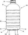
图1为本发明实施形态的吹塑容器主视图。Fig. 1 is a front view of a blow molded container according to an embodiment of the present invention.
图2为图1所示容器的侧视图。Figure 2 is a side view of the container shown in Figure 1 .
图3为图1所示容器的俯视图。Fig. 3 is a top view of the container shown in Fig. 1 .
图4为容器躯干部的图2A-A线横剖视图。Fig. 4 is a cross-sectional view of the trunk portion of the container along the line A-A of Fig. 2 .
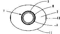
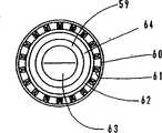
图5为图1所示容器的仰视图。Fig. 5 is a bottom view of the container shown in Fig. 1 .
图6为图1所示容器底部的局部剖视主视图。Fig. 6 is a partially cutaway front view of the bottom of the container shown in Fig. 1 .
图7为容器躯干部第1实施例的说明图。Fig. 7 is an explanatory diagram of a first embodiment of a container body.
图8为容器躯干部第2实施例的吹塑容器侧视图。Fig. 8 is a side view of the blow molded container of the second embodiment of the container body.
图9为第2实施例的说明图,(a)为侧壁面的表面图,(b)为图(a)的A-A线横剖视图,(c)为图(a)的B-B线横剖视图。Fig. 9 is the explanatory drawing of the 2nd embodiment, (a) is the surface view of side wall surface, (b) is the A-A line cross-sectional view of figure (a), (c) is the B-B line cross-sectional view of figure (a).
图10为容器躯干部第3实施例的吹塑容器局部剖视主视图。Fig. 10 is a partial sectional front view of a blow molded container according to a third embodiment of the container body.
图11为图10所示容器的局部剖视侧视图。Fig. 11 is a side view, partially in section, of the container shown in Fig. 10 .
图12为容器躯干部的图11A-A线横剖视图。Fig. 12 is a cross-sectional view of the container body along line A-A of Fig. 11 .
图13为容器躯干部的横剖视图,(a)为扁平的大致六角形、(b)为扁平的大致八角形。Fig. 13 is a transverse cross-sectional view of a container body, (a) being a flat approximately hexagonal shape, and (b) being a flat approximately octagonal shape.
图14为容器底部第4实施例的吹塑容器主视图。Fig. 14 is a front view of the blow molded container of the fourth embodiment of the bottom of the container.
图15为图14所示容器的仰视图。Figure 15 is a bottom view of the container shown in Figure 14 .
图16为增强肋又一实施例的说明图,(a)为底部主视图,(b)为仰视图。Fig. 16 is an explanatory diagram of another embodiment of the reinforcing rib, (a) is a bottom front view, and (b) is a bottom view.
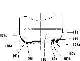
图17为容器底部第5实施例的吹塑容器主视图。Fig. 17 is a front view of the blow molded container of the fifth embodiment of the bottom of the container.
图18为图17所示容器的侧视图。Figure 18 is a side view of the container shown in Figure 17 .
图19为图17所示容器的仰视图。Figure 19 is a bottom view of the container shown in Figure 17 .
图20为图17所示容器底部的横肋说明图,(a)为局部剖视主视图,(b)为局部剖视侧视图。Fig. 20 is an explanatory view of the transverse ribs at the bottom of the container shown in Fig. 17, (a) is a partial sectional front view, and (b) is a partial sectional side view.
图21为容器底部变形时的说明图。Fig. 21 is an explanatory diagram when the container bottom is deformed.
图22为容器底部第6实施例的容器主视图。Fig. 22 is a front view of the container of the sixth embodiment of the container bottom.
图23为图22所示容器的仰视图。Figure 23 is a bottom view of the container shown in Figure 22 .
图24为图22所示容器底部的局部剖视图。Fig. 24 is a partial cross-sectional view of the bottom of the container shown in Fig. 22 .
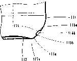
图25为容器底部第7实施例的容器的侧视图。Fig. 25 is a side view of the container of the seventh embodiment of the container bottom.
图26为图25所示容器的仰视图。Figure 26 is a bottom view of the container shown in Figure 25 .
图27为沿图26A-A线的容器底部局部剖视主视图。Fig. 27 is a partial sectional front view of the bottom of the container taken along line A-A of Fig. 26.
图28为容器底部第8实施例的容器的主视图。Fig. 28 is a front view of the container of the eighth embodiment of the container bottom.
图29为图28所示容器的仰视图。Figure 29 is a bottom view of the container shown in Figure 28 .
图30为容器底部的剖视图。Figure 30 is a cross-sectional view of the bottom of the container.
图31为容器口部第9实施例的吹塑容器的主视图。Fig. 31 is a front view of a blow molded container according to a ninth embodiment of the container opening.
图32为图31所示容器的侧视图。Figure 32 is a side view of the container shown in Figure 31.
图33为容器口部第10实施例的容器口部的说明图,(a)为口部主视图,(b)为图(a)的A-A线外形剖视图。Fig. 33 is an explanatory view of the container mouth of the tenth embodiment of the container mouth, (a) is a front view of the mouth, and (b) is an outline cross-sectional view taken along line A-A of figure (a).
实施发明的最佳形态The best form for carrying out the invention
下面,参照图纸说明本发明的实施例。Next, embodiments of the present invention will be described with reference to the drawings.
在图1和图2中,A为由直接吹塑或延伸吹塑成形的薄壁扁平状吹塑容器,由口部1、肩部2、躯干部3和底部4构成,树脂原料采用聚乙烯(PE)、聚丙烯(PP)、聚对苯二甲酸乙二脂(PET)及其它合成树脂,以单层或层叠形式吹塑成形。In Figure 1 and Figure 2, A is a thin-walled flat blow-molded container formed by direct blow molding or stretch blow molding, consisting of a
口部1由上部口筒部5、位于口部中间部的把持环6和从其下方与肩部连接的下部口筒部7构成。The
在上部口筒部5的外周面设有螺纹8,把持环6的外周面从口部1的上部口筒部5和下部口筒部7凸出,沿着外周面的局部或全周刻设有滚花9。
下部口筒部7具有手指把持所需的一定高度,其外周直径小于把持环,但大于上部口筒部5,与肩部2连接。The lower mouthpiece 7 has a certain height required for fingers to hold, and its outer diameter is smaller than the grip ring, but larger than the upper mouthpiece 5 , and is connected with the
在肩部2与躯干部3的中间形成阶梯部10。如图3和图4所示,肩部2和躯干部3的剖面形状是前后呈椭圆形、两侧为平面的扁平状剖面11。A stepped portion 10 is formed between the
躯干部3由前后壁12和左右侧壁13构成。侧壁13为将前后壁12的椭圆面切裁后形成的垂直平面,其上端延伸到肩部2,由狭窄的弧状壁14将其端边与前后壁12的端部之间连接在一起。The
躯干部3的前后壁12沿着上下方向等间隔地配设横向延伸的凹槽15,凹槽15使前后壁面12形成了上下方向波纹形的壁面。The front and
左右侧壁13以一定的角度与弧状壁14相交,在侧壁13的表面,沿着上下方向等间隔地配设多个圆形的增强凹部16。The left and
在躯干部3的下端部,配设与上部之间有高低差的鼓出状周壁17,与底部4连接。At the lower end of the
如图1、图2、图5和图6所示,底部4由底周壁18和底壁19构成。底周壁18由稍许倾斜的前后壁20和以所定角度倾斜的左右侧壁21形成。As shown in FIGS. 1 , 2 , 5 and 6 , the
又如图5所示,倾斜的侧壁21的下端部21a和前后壁20的下端部20a与容器中心的距离大体一致,尽可能减小其差别。Also as shown in FIG. 5 , the distance between the
换言之,将底壁19的外周做成长径与短径之差较小的椭圆状,侧壁21呈倾斜状,其上端与扁平状躯干部的长径部侧壁13连接,下端与外径小于扁平状躯干部长径部的底壁19的外周连接。In other words, the outer periphery of the
这样,就使侧壁21的下端部外径小于上端部外径、即扁平状躯干部的椭圆的长径,在吹塑成形时,可根据倾斜角度相应减少吹塑比,如图6所示,下端部21的壁厚大于侧壁13的壁厚。In this way, the outer diameter of the lower end of the
其倾斜角度由所需的躯干部壁厚和底壁周边的壁厚来设定。The angle of inclination is set by the desired wall thickness of the trunk and the perimeter of the bottom wall.
在底周壁18与躯干部3的鼓出状周壁17间的连接部上,沿着全周设有上横肋22,在前后壁20上,以一定间隔设置多个纵肋23。On the connecting portion between the bottom
在底周壁18的下端部,沿着全周配设下横肋24,在该下横肋24的下侧,连接着底壁19,该底壁19做成中央部向上凹陷的弯曲面25。At the lower end of the bottom
下面说明成形方法。本发明的容器是用传统的直接吹塑或延伸吹塑成形。Next, the forming method will be described. The containers of the present invention are formed by conventional direct blow molding or stretch blow molding.
按照传统技术,在采用PP树脂的直接吹塑制成可确保保形性且能简单压碎的薄壁容器时,使用0.067g/ml的树脂重量。但本发明通过在躯干部壁面和底部周壁上配设增强部,减少了单位容量的树脂重量,将树脂重量降低到0.015-0.05g/ml。按照传统技术,在采用PE树脂的直接吹塑制成可确保保形性且能简单压碎的薄壁容器时,要使用0.096g/ml的树脂重量,但本发明通过在躯干部壁面和底部周壁上配设增强部,减少了单位容量的树脂重量,将树脂重量降低到0.021-0.07g/ml。在采用PET树脂时,本发明在躯干部壁面和底部周壁上配设增强部,通过双轴延伸吹塑成形也可获得相同效果。According to conventional techniques, when direct blow molding of PP resin is used to form thin-walled containers that ensure shape retention and can be easily crushed, a resin weight of 0.067 g/ml is used. However, the present invention reduces the resin weight per unit capacity to 0.015-0.05 g/ml by arranging reinforcing parts on the wall surface of the trunk and the peripheral wall of the bottom. According to the traditional technology, when using direct blow molding of PE resin to make a thin-walled container that can ensure shape retention and can be easily crushed, a resin weight of 0.096g/ml should be used, but the present invention uses the The reinforcing part is arranged on the peripheral wall of the bottom, which reduces the resin weight per unit capacity to 0.021-0.07g/ml. When PET resin is used, the present invention arranges reinforcing parts on the wall surface of the trunk part and the peripheral wall of the bottom, and the same effect can also be obtained by biaxial stretch blow molding.
薄壁容器躯干部周壁的厚度小于0.6mm,但为了更便于压碎,躯干部周壁的厚度最好小于0.3mm。Thickness of the peripheral wall of the trunk of the thin-walled container is less than 0.6 mm, but for easier crushing, the thickness of the peripheral wall of the trunk is preferably less than 0.3 mm.
在实施例中,躯干部侧壁的厚度为0.1-0.15mm,躯干部的前后壁为0.15-0.3mm。In an embodiment, the thickness of the side wall of the trunk is 0.1-0.15 mm, and the thickness of the front and rear walls of the trunk is 0.15-0.3 mm.
下面说明采用上述结构的作用和效果。The action and effect of adopting the above structure will be described below.
先说明躯干部3的作用和效果。前后壁12的强度因横向延伸的凹槽15而增大,侧壁13与弧状壁14的交叉部形成了垂直的角部,具有与增强肋相同的作用,与侧壁13一起起着躯干部支柱的作用。The function and effect of the
又由于在侧壁13表面等间隔地配设多个增强凹部16,因此可提高躯干部的压曲强度。Furthermore, since a plurality of reinforcing recesses 16 are arranged at equal intervals on the surface of the
侧壁13的表面为平面,故在成形后容器的传送工序中,当前后的容器碰撞时是与侧壁13作面接触,不会出现变形。The surface of the
又由于侧壁13是面接触,因此使传送容器的长径方向与传送方向并列,容器的排列不会紊乱。And because the
下面说明底部4的作用和效果。底周壁18由稍许倾斜的前后壁20和以一定角度倾斜的左右侧壁21形成。因侧壁21倾斜,故侧壁21的下端部21a的壁厚大于侧壁13。The function and effect of the bottom 4 will be described below. The bottom
由此,可增大底周壁的强度,提高抗落下冲击的强度。Thereby, the strength of the bottom peripheral wall can be increased, and the strength against falling impact can be improved.
另外,底周壁18因上下的横肋22、24和纵肋23而增大强度,故可防止容器底部周壁在容器落下时因冲击而变形或者产生裂缝,还可提高抗压曲的强度。In addition, the bottom
下面说明与容器壁厚的关系。例如,在采用PP时,若将躯干部壁面的厚度减薄至0.6mm以下,虽然也会因容器的落下冲击造成底部周壁变形或者裂缝,但即使在那种场合,通过采用上述结构,也完全可防止变形或裂缝的产生。The relationship with the wall thickness of the container will be described below. For example, when PP is used, if the thickness of the wall surface of the trunk is reduced to less than 0.6 mm, although the bottom wall will be deformed or cracked due to the impact of the drop of the container, even in that case, by adopting the above structure, it is also possible Completely prevents deformation or cracks.
下面说明口部的作用和效果。口部1虽然比躯干部2壁厚,但比传统的产品相比薄,故通过在口部的中间部形成向外凸出状的把持环6来增大口部的强度。The function and effect of the mouth will be described below. Although the
由于在把持环的下面设定有可伸入手指的一定高度,因此可把持容器,在其外周面通过设置滚花9,以使把持的容器不会转动。Because the certain height that can stretch into finger is set under the holding ring, therefore container can be held, knurling 9 is set on its outer peripheral surface, so that the held container can not rotate.
下面说明躯干部、底部和口部的变形实施例。Modified embodiments of the trunk, bottom and mouth are described below.
(第1实施例)(first embodiment)
先说明躯干部的第1实施例。配设在侧壁表面的增强部在上述实施形态中采用的是圆形的增强凹部16,但也可配设图7所示的增强部。First, the first embodiment of the torso will be described. The reinforcement portion disposed on the side wall surface is the circular reinforcement recess 16 used in the above embodiment, but the reinforcement portion shown in FIG. 7 may also be disposed.
在图7a中,配设了方形的平底凹部16a。In FIG. 7a, a square-shaped flat-bottomed
在图7b中,配设了横向延伸的凹形肋16b。In Fig. 7b, transversely extending concave ribs 16b are provided.
在图7c中,方形的平底凹部16c中配设了X字形的凸状肋16d。In FIG. 7c, the X-shaped
在图7d中,在侧壁的表面配设了X字状的凹槽16e或凸状肋16f。采用凸状肋16f时,肋的上端面为面接触,可获得与实施形态相同的作用和效果。In FIG. 7d, X-shaped grooves 16e or convex ribs 16f are arranged on the surface of the side wall. When the convex rib 16f is used, the upper end surface of the rib is in surface contact, and the same action and effect as in the embodiment can be obtained.
图7e是配设了沿上下方向延伸的波状凹状肋。Fig. 7e is provided with corrugated concave ribs extending in the vertical direction.
这些增强部均可实现上述侧壁的作用和效果。These reinforcing parts can all realize the functions and effects of the above-mentioned side walls.
(第2实施例)(second embodiment)
下面说明改变了侧壁结构的第2实施例。Next, a second embodiment in which the side wall structure is changed will be described.
本实施例改变了上述实施形态的躯干部侧壁形状,口部、肩部、底部等的结构、躯干部的剖面形状以及前后壁的结构相同,故给图的符号添加了a字并作简单说明,以下以侧壁为中心说明。This embodiment has changed the shape of the side wall of the trunk portion of the above-mentioned embodiment, the structure of the mouth, shoulder, bottom, etc., the cross-sectional shape of the trunk portion, and the structure of the front and rear walls are the same, so the symbols of the figure have added a word and made it simple. Description, the following description will be centered on the side wall.
在图8中,吹塑容器Aa由口部1a、肩部2a、躯干部3a和底部4a构成。In FIG. 8, a blow molded container Aa is constituted by a mouth portion 1a, a shoulder portion 2a, a trunk portion 3a and a bottom portion 4a.
躯干部3a由与前述实施形态相同形状的前后壁12a和左右侧壁30构成。The trunk portion 3a is composed of the front and rear walls 12a and the left and right side walls 30 having the same shapes as those of the above-mentioned embodiment.
侧壁30沿其表面的全周边缘形成一定宽度的端边部31,该端边部31的内侧为平底凹部32。The side wall 30 forms an
平底凹部32在其底面沿着上下方向以一定间隔配设横向延伸且与左右端边部31连接的多个凸状肋33。A plurality of
其作用和效果是,侧壁30的端边部31起着纵肋的作用,凸状肋33则成为横向的增强肋,故增大了侧壁30的强度,具有与上述实施形态的侧壁相同的作用和效果。Its role and effect are that the
下面说明配设在平底凹部32上的各种增强部的变形例。上述实施例是将凸状肋33作为增强部,但也可配设图9所示的增强部。Modifications of various reinforcing parts arranged on the flat-bottomed recessed
图9a配设了X字状的凸状肋33a。In Fig. 9a, X-shaped convex ribs 33a are arranged.
图9b配设了横向延伸的凸状肋33b,并在上下方向配设一条或两条纵向凸状胁33c。Fig. 9b is provided with a laterally extending
这些增强部均可获得与上述侧壁相同的作用和效果。Each of these reinforcements can obtain the same function and effect as that of the above-mentioned side wall.
(第3实施例)(third embodiment)
下面说明改变了躯干部前后面形状的第3实施例。Next, a third embodiment in which the front and rear shapes of the trunk are changed will be described.
口部、肩部、底部等的结构及躯干部剖面形状的结构与上述实施形态相同,故给符号添加了b字并作简单说明,以下以前后面的结构为中心说明。The structure of the mouth, shoulders, bottom, etc. and the cross-sectional shape of the torso are the same as those of the above-mentioned embodiment, so the b word is added to the symbol and briefly explained, and the following front and rear structures are mainly explained.
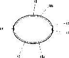
如图10至图12所示,躯干部3b由包括前壁40a和后壁40b的剖面为椭圆形的前后壁40和左右侧壁41构成。侧壁41为将前后壁40的横剖面的椭圆面切裁后形成的垂直平面,其上端延伸至肩部2b,其端边与前后壁40端部之间由狭窄的弧状壁42连接。As shown in FIGS. 10 to 12 , the
在躯干部3b的前后壁40的两壁40a、40b上,沿上下方向等间隔地配设横向延伸的圆弧状凹部43,利用凹部43,使前后壁40沿上下方向形成峰顶和谷底连续的、弯曲成波状的壁面即波面。On the two
也可只在前壁40a或后壁40b中的任一方形成由凹部43形成的波面。The wave front formed by the
凹部43的个数为偶数,波面的峰顶部位于前后壁40的上下方向的中央。The number of
左右的侧壁41以一定的角度与弧状壁42相交,在侧壁41的表面,沿上下方向等间隔地配设多个圆形的增强凹部44。The left and
下面说明采用上述结构的作用和效果。The action and effect of adopting the above structure will be described below.
躯干部3b的前后壁40由于在其前壁40a和后壁40b双方或在任一方上等间隔地配设横向延伸的凹部43,并沿着上下方向将壁面做成弯曲成波状的波面,因此可增大躯干部的刚性和抗压强度。The front and
并且,通过将凹部个数设定为偶数,使波面的峰顶部位于躯干部的壁面中央。In addition, by setting the number of concave portions to an even number, the peak of the wave front is positioned at the center of the wall surface of the trunk portion.
在躯干部的波面的峰顶部与谷底部之间,峰顶部的刚性更强。Between the top of the peak and the bottom of the valley of the wave surface of the trunk portion, the top of the peak is more rigid.
在把持容器时,通常是用手指夹持躯干部的壁面中央,而若在此部位形成峰顶部,就可防止躯干部的变形。When holding the container, usually the center of the wall of the trunk is clamped with fingers, and if a peak is formed at this position, deformation of the trunk can be prevented.
若在躯干部上下之间施加弯曲力矩,则容易使躯干部中央变形,但当中央部是峰顶部时,就可避免容器的变形。If a bending moment is applied between the upper and lower parts of the body, the center of the body is easily deformed, but when the center is a peak, deformation of the container can be avoided.
又由于侧壁41为垂直平面,且以一定的角度与前后壁40端部的弧状壁42相交,因此其交点作为角部起着与增强肋相同的作用,增大躯干部3b的弯曲强度。And because the
下面,通过实验例来说明躯干部的前后壁面形成波面、侧壁形成垂直平面即平直面的效果。Next, the effect that the front and rear walls of the torso form a wave surface and the side walls form a vertical plane, that is, a straight plane, will be described through an experimental example.
(实验例1)(Experimental example 1)
以PP树脂作为原料,使用17.5g树脂来成形600ml的容器(单位容量的树脂重量为0.0292g/ml),其口部、肩部、底部的形状与实施形态相同,躯干部的侧壁为平直面,而其前后壁形状改变。Using PP resin as a raw material, 17.5g of resin is used to form a 600ml container (the resin weight per unit capacity is 0.0292g/ml). It is a flat surface, while the shape of its front and rear walls changes.
对有无由横向延伸的凹部形成的、沿上下方向弯曲成波状的波面的躯干部作了强度测定。The strength was measured for the torso with or without the wavy surface curved in the vertical direction formed by the concave portion extending in the lateral direction.
与无波面时相比,躯干部强度在设单侧波面时为+84.7%,双侧波面时则为+167%,抗压强度也增大。Compared with the case of no wave surface, the strength of the torso is +84.7% when the wave surface is set on one side, and +167% when the wave surface is on both sides, and the compressive strength is also increased.
(实验例2)(Experimental example 2)
其次,关于侧壁形成垂直面、即平直面的效果,对躯干部壁面为无侧壁的椭圆柱面的场合与有垂直侧壁(平直面)的场合进行比较,测定了躯干部强度,与无平直面时相比,压曲强度为+22.9%、短径方向的刚性为+19.1%、长径方向的刚性为+48%、抗压强度为+12.5%,可见将侧壁形成平直面后,可提高压曲强度、躯干部的刚性以及抗压强度。Secondly, regarding the effect of the side wall forming a vertical surface, that is, a straight surface, the case where the wall surface of the trunk part is an elliptical cylindrical surface without a side wall is compared with the case with a vertical side wall (flat face), and the strength of the trunk part is measured. Compared with the case of no flat surface, the buckling strength is +22.9%, the rigidity in the short diameter direction is +19.1%, the rigidity in the long diameter direction is +48%, and the compressive strength is +12.5%. It can be seen that By forming the side walls into flat surfaces, the buckling strength, the rigidity of the trunk, and the compressive strength can be increased.
(实验例3)(Experimental example 3)
接着,采用实验例1用过的容器,即,两面具有由横向延伸的凹部形成的、沿上下方向弯曲成波状的容器,改变配设在躯干部壁面的凹部个数,对躯干部中央的刚性进行比较,与凹部个数为3个相比,使躯干部中心凹陷一定量的力在4个时为169%、5个时为112%、6个时为148%,从该结果中可以看出,凹部个数为偶数时,换言之,当波面的峰顶部位于躯干部中央时,躯干部的强度比个数为奇数时增大。Next, using the container used in Experimental Example 1, that is, a container that is formed by laterally extending recesses on both sides and bent into a wave shape in the up and down direction, the number of recesses arranged on the wall surface of the trunk portion is changed, and the rigidity to the center of the trunk portion is changed. For comparison, compared with the number of recesses being 3, the force to dent the center of the trunk by a certain amount was 169% when there were 4, 112% when there were 5, and 148% when there were 6. From the results, it can be seen that It can be seen that when the number of concave parts is an even number, in other words, when the peak of the wave front is located in the center of the trunk part, the intensity of the trunk part is greater than when the number is an odd number.
本项实验结果也可应用于将侧壁13做成垂直平面的、本发明实施形态的吹塑容器。The results of this experiment can also be applied to the blow-molded container of the embodiment of the present invention in which the
上述第3实施例采用的是剖面椭圆形的扁平状,但也可是图13所示的六角形或八角形的扁平状。The above-mentioned third embodiment adopts a flat shape with an elliptical cross section, but it may also be a flat shape with a hexagonal or octagonal shape as shown in FIG. 13 .
下面说明底部的变形实施例。A modified embodiment of the bottom will be described below.
先说明配设在底周壁上的上下横肋和纵肋。上述实施形态的容器的纵肋23采用了图1所示的呈矩形凹部的增强肋,但纵肋也可是将凹部连续成波状的波状肋或椭圆形凹部(未图示),而不限于矩形凹部。First, the upper and lower transverse ribs and longitudinal ribs arranged on the bottom peripheral wall will be described. The
作为配设在底周壁上的增强肋,以上说明的是将上横肋和下横肋以及配设在上横肋与下横肋之间的纵肋组合形成的增强肋,但也可根据容器的壁厚和使用的树脂,只设置其中一种肋,或者由两种肋组合配设。As the reinforcement rib arranged on the bottom peripheral wall, the reinforcement rib formed by combining the upper transverse rib and the lower transverse rib and the longitudinal rib arranged between the upper transverse rib and the lower transverse rib has been described above, but Depending on the thickness of the wall and the resin used, only one of the ribs is provided, or a combination of two ribs is provided.
(第4实施例)(fourth embodiment)
本实施例是将上述实施形态的底周壁增强肋用于圆形容器,是在肩部、躯干部和底部形成剖面圆形这一点上与上述实施形态不一样。This embodiment uses the bottom peripheral wall reinforcing rib of the above-mentioned embodiment for a circular container, and differs from the above-mentioned embodiment in that the cross-section of the shoulder, trunk, and bottom is circular.
在图14中,剖面圆形的合成树脂制薄壁容器AC由口部50、肩部51、躯干部52和底部53构成。In FIG. 14 , a synthetic resin thin-walled container AC having a circular cross section is composed of a
口部50的结构与上述实施形态相同,省略说明。The structure of the
肩部51和躯干部52的横剖面为圆形,在肩部51与躯干部52之间形成阶梯部54,在躯干部52的躯干周壁55上,沿上下方向等间隔地配设横向延伸的凹槽56,利用凹槽56,使躯干周壁55的壁面成为上下方向波状起伏的壁面。The cross-section of the
在躯干部52的下端部,配设与上部之间具有阶梯的鼓出状周壁57,与底部53连接。At the lower end portion of the
如图14和图15所示,底部53由底周壁58和底壁59构成,底周壁58以一定角度倾斜。As shown in FIGS. 14 and 15 , the
在底周壁58与躯干部52的鼓出状周壁57之间的连接部设有沿全周的上横肋60,在底周壁58的全周面,以一定间隔设有多个纵肋61。An upper
在底周壁58的下端部配设沿全周的下横肋62,该下横肋62的下侧与底壁59连接,该底壁59的中央部向上凹陷形成弯曲面63。A lower
如图15所示,底壁59的外周直径明显小于躯干周壁55,底周壁58的上端与躯干周壁55连接,底周壁58的下端部64与底壁外周连接,呈倾斜状。As shown in Figure 15, the outer peripheral diameter of the
下面说明采用上述底部结构的作用和效果。The action and effect of adopting the above-mentioned bottom structure will be described below.
由于底周壁58的下端部64的直径小于躯干周壁55,减少了吹塑比,因此壁厚大于躯干周壁55,增大了底周壁58的强度,提高抗落下冲击的强度。Because the diameter of the
又由于利用增强肋60、61、62增大了底周壁58的强度,故可防止容器底部周壁在容器落下时因冲击而变形或者产生裂缝,还可提高抗压曲的强度。And because the strength of the bottom
下面说明底周壁的增强肋采用波状肋的变形实施例。A modification example in which corrugated ribs are used as reinforcing ribs on the bottom peripheral wall will be described below.
在图16中,52a为躯干部,53a为底部。底部53a由底周壁58a和底壁59a构成。In FIG. 16, 52a is a trunk part, and 53a is a bottom part. The bottom portion 53a is composed of a bottom peripheral wall 58a and a bottom wall 59a.
在躯干部52a与侧周壁58a之间的连接部设有上横肋60a,底周壁58a在其下端与底壁59a连接。An upper transverse rib 60a is provided at a connecting portion between the trunk portion 52a and the side peripheral wall 58a, and the bottom peripheral wall 58a is connected to the bottom wall 59a at its lower end.
在底周壁58a的表面配设波状肋65,其沿周向形成呈波状延伸的凹部或凸部,可增大上下方向和周向的强度。Corrugated ribs 65 are arranged on the surface of the bottom peripheral wall 58a to form concave or convex portions extending in a wave shape along the circumferential direction, thereby increasing the strength in the vertical direction and the circumferential direction.
上述实施例是在躯干部的壁面配设横向延伸的凹槽,将躯干部做成沿上下方向波状起伏的壁面,但也可不用凹槽而配设波状肋,也可将躯干部壁面作为平直面配设适量的增强肋。In the above-mentioned embodiment, grooves extending transversely are arranged on the wall surface of the trunk portion, and the trunk portion is made into a wavy wall surface along the up-and-down direction. The right amount of reinforcement ribs are provided on the straight face.
(第5实施例)(fifth embodiment)
下面说明将底部的增强肋做成特定形状的实施例。An embodiment in which the reinforcing ribs at the bottom are made into a specific shape will be described below.
容器的口部、肩部和躯干部的结构与上述实施形态的容器相同,故添加d字并省略说明,只对底部作一说明。The structure of the mouth, shoulder and trunk of the container is the same as the container of the above-mentioned embodiment, so the d word is added and the description is omitted, and only the bottom is described.
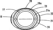
如图17至图20所示,底部4d由底周壁70和底壁71构成。底周壁70由稍许倾斜的前后壁72和倾斜一定角度的左右侧壁73形成。As shown in FIGS. 17 to 20 , the
在底周壁70的下端部,沿全周配设横肋74,该横肋74的下侧与中央部形成向上凹陷的弯曲面75的底壁71的接地底端壁71a连接。At the lower end of the bottom
横肋74是由上侧壁74a与下侧壁74b形成的凹槽,横肋74的上下两个侧壁的连接部以及各侧壁74a、74b与底周壁70间的连接部均以圆弧状连接。The
在侧壁73的局部,与侧壁73的倾斜角度相关,下侧壁74b大致垂直,上侧壁74a稍许倾斜。In a part of the
下面说明采用上述底部结构的作用和效果。The action and effect of adopting the above-mentioned bottom structure will be described below.
底周壁70由稍许倾斜的前后壁72和倾斜一定角度的左右侧壁73形成,通过使侧壁73倾斜,如图20所示,可使侧壁73的下端部73a的壁厚t1大于躯干部侧壁的壁厚t2。The bottom
由此,可增大底周壁70的强度,提高抗落下冲击的强度。Thereby, the strength of the bottom
并且,在侧壁73的局部,横肋74的下侧壁74b大致垂直,横肋74位于底壁74的接地底端壁71a的附近,再加上壁面厚,可明显增大底周壁70的压曲强度。Moreover, in the part of the
与底周壁70上不设肋的壁面作比较性实验,就可确认压曲强度增加约25%。In a comparative experiment with the bottom
若树脂重量少,容器底部的壁厚也小,则施加在容器上的重量会使底周壁70和底壁71从图21中的a状态变形为b状态。If the weight of the resin is small and the thickness of the bottom of the container is small, the weight applied to the container will deform the bottom
在此场合,横肋74的下侧壁74b将底周壁70的下端部后下压、使接地点向外移动,并使底壁71本身弯曲变形,中央部略微上升,但因下侧壁74b大致垂直,故可增大抗压曲的强度。In this case, the
并且,因躯干部和底部的强度增大而可确保容器的形状,又由于利用横肋74可明显提高底部的压曲强度,因此可确保容器的直立稳定性。Furthermore, the shape of the container can be ensured due to the increased strength of the trunk and the bottom, and the vertical stability of the container can be ensured because the buckling strength of the bottom can be significantly improved by using the
(第6实施例)(sixth embodiment)
下面说明将上述第5实施例用于横剖面为圆形的容器的实施例。Next, an embodiment in which the above-mentioned fifth embodiment is applied to a container having a circular cross section will be described.
在图22中,横剖面为圆形的薄壁吹塑容器Ae由口部80、肩部81、躯干部82和底部83构成。In FIG. 22 , a thin-walled blow-molded container Ae having a circular cross section is composed of a mouth portion 80 , a shoulder portion 81 , a body portion 82 and a
肩部81和躯干部82的横剖面为圆形,在肩部81与躯干部82之间形成阶梯部84,在躯干部82的躯干周壁85上,沿上下方向等间隔地配设横向延伸的凹槽86,利用凹槽86,使躯干周壁85成为沿上下方向波状起伏的壁面。The cross section of the shoulder portion 81 and the trunk portion 82 is circular, and a stepped portion 84 is formed between the shoulder portion 81 and the trunk portion 82. On the trunk peripheral wall 85 of the trunk portion 82, horizontally extending bars are arranged at equal intervals in the up and down direction. Groove 86. The groove 86 makes the trunk peripheral wall 85 a wall surface that undulates in the vertical direction.
在躯干部82的下端部,配设与上部之间具有阶梯的鼓出状周壁87,与底部83连接。At the lower end portion of the body portion 82 , a swollen peripheral wall 87 having a step between the upper portion and the upper portion is arranged, and is connected to the
如图22和图23所示,底部83由底周壁88和底壁89构成。底周壁88倾斜一定角度,其下端部88a与中央部向上凹陷形成弯曲面90的底壁89的接地底端壁89a连接。As shown in FIGS. 22 and 23 , the
底壁89的接地底端壁89a的外周直径明显小于躯干周壁85,底周壁88的上端与鼓出状周壁87连接,底周壁88的下端部88a与底壁89的接地底端壁89a的外周连接,呈倾斜状。The outer diameter of the grounded
在底周壁88的下部沿全周配设横肋91。A
如图24所示,该横肋91的剖面形状与上述第5实施例相同,成为由上侧壁91a、下侧壁91b的两个侧壁和底周壁88的壁表面构成的三角形,横肋91的各侧壁91a、91b与底周壁88壁面的连接部以及侧壁91a与侧壁91b的连接部呈圆弧连接。As shown in FIG. 24 , the cross-sectional shape of the
横肋91的下侧壁91b以一定的角度与底周壁88相交,与底周壁88的倾斜角度相关,横肋91的下侧壁91b大致垂直,上侧壁91a稍许倾斜。The lower side wall 91b of the
下面说明采用上述底部结构的作用和效果。The action and effect of adopting the above-mentioned bottom structure will be described below.
底周壁88的下端部88a的壁厚t1因直径小于躯干周壁85而减少了吹塑比,故其厚度小于躯干周壁85的壁厚t2,可增大底周壁88的强度,提高抗落下冲击的强度。The wall thickness t1 of the
并且,横肋91的下侧壁91b大致垂直,横肋91位于底壁89的接地底端壁89a的附近,再加上壁面厚,可明显增大底部的压曲强度。Moreover, the lower side wall 91b of the
(第7实施例)(the seventh embodiment)
下面说明将上述第5实施例的底周壁的肋变形后的实施例。Next, an embodiment in which the ribs of the bottom peripheral wall of the above-mentioned fifth embodiment are deformed will be described.
本实施例是在上述第5实施例的底周壁上改用横肋,在相当于该横肋位置的底周壁的侧壁下端部分,以所定间隔配设凹部。In this embodiment, transverse ribs are used instead of the bottom peripheral wall of the fifth embodiment above, and recesses are arranged at predetermined intervals at the lower end portion of the side wall of the bottom peripheral wall corresponding to the position of the transverse ribs.
在图25中,薄壁的扁平吹塑容器Af的口部1、肩部2和躯干部3与第6实施例相同,故对符号添加f,且只对底部100作出说明。In FIG. 25, the
在图25至图27中,100为扁平状容器的底部,由底周壁101和底壁102构成。In FIGS. 25 to 27 , 100 is the bottom of the flat container, which is composed of a bottom peripheral wall 101 and a
底周壁101由前后壁103和左右侧壁104构成。侧壁104与第5实施例相同地倾斜一定角度,在侧壁104的下端部104a,以一定间隔在接地底端壁102a的附近配设凹部105。The bottom peripheral wall 101 is composed of front and
如图26和图27所示,凹部105具有方形的平底壁106、连接该平底壁106与底周壁101壁面的上下连接壁107a、107b以及左右连接壁108a、108b。下侧的连接壁107b位于底周壁101下端部的接地底端壁102a的附近,大致呈垂直状。26 and 27, the
下面说明本实施例的作用和效果。由于下侧的连接壁107b位于底周壁101下端部的接地底端壁102的附近且大致呈垂直状,因此,与上述第5实施例的横肋相同,可增大底部的压曲强度。The action and effect of this embodiment will be described below. Since the lower connecting wall 107b is located near the grounded
(第8实施例)(eighth embodiment)
下面说明将上述第7实施例中的凹部用于圆形容器的实施例。Next, an embodiment in which the concave portion of the seventh embodiment described above is used in a circular container will be described.
本实施例是在上述第7实施例的底周壁的下端部等间隔地配设凹部。In this embodiment, recesses are arranged at regular intervals on the lower end portion of the bottom peripheral wall of the seventh embodiment.
如图28至图30所示,薄壁的圆形吹塑容器Ag的底部110由底周壁111和底壁112构成。底周壁111倾斜一定角度,其下端部111a与中央部向上凹陷形成弯曲面的底壁112的接地底端壁112a连接。As shown in FIGS. 28 to 30 , the
底壁112的接地底端壁112a的外周直径明显小于躯干周壁,底周壁111的上端与躯干周壁连接,底周壁111的下端部111a与底壁112的接地底端壁112a的外周连接,呈倾斜状。The diameter of the outer circumference of the grounded
在底周壁111的下端部111a上,以一定间隔在接地底端壁112a的附近配设凹部113。On the
凹部113具有方形的平底壁114、连接该平底壁114与底周壁111壁面的上下连接壁115a、115b以及左右连接壁116a、116b。下侧的连接壁115b位于底周壁111的下端部111a的接地底端壁112附近,大致呈垂直状。The
下面说明本实施例的作用和效果。由于下侧的连接壁115b位于底周壁111的下端部111a的接地底端壁112a的附近且大致呈垂直状,因此,与上述第5、第6实施例的横肋相同,可增大底部的压曲强度。The action and effect of this embodiment will be described below. Since the lower connecting wall 115b is located near the grounded
上述第7和第8实施例是将凹部做成方形,但也可是椭圆形凹部或正方形凹部。In the above-mentioned seventh and eighth embodiments, the concave portion is made into a square shape, but an elliptical concave portion or a square concave portion may also be used.
(第9实施例)(Ninth embodiment)
下面说明口部的变形实施例。Next, a modified example of the mouth will be described.
在图31和图32中,吹塑容器Ah由口部120、肩部121、躯干部122和底部123构成、肩部121、躯干部122和底部123与前述实施形态中的容器相同。In Figs. 31 and 32, the blow container Ah is composed of a
口部120由上部口筒部124、位于口部中间部的颈环125和从其下方延伸到肩部的下部口筒部126构成。
在上部口筒部124的外周面上设有螺纹127,在颈环125的外周面上,沿全周刻设有滚花128。
下部口筒部126具有手指伸入该下部口筒部126并把持容器所需的高度,与肩部121连接。The
口部120壁厚比肩部121和躯干部122厚,但与传统产品相比仍属较薄,故通过在口部的中间部形成颈环125,并在其外周面上设有滚花128,以增大口部120的强度,并且在容器传送时把持容器不让其乱动,并在拧紧盖子时不使容器转动。The wall thickness of the
在颈环125的下方设有一定高度的下部口筒部126,故也可将手指伸入颈环125与肩部121之间的下部口筒部126把持容器。Below the
由此,在使用时可以简单地开闭盖子。Thereby, the cover can be easily opened and closed during use.
(第10实施例)(the tenth embodiment)
前述实施形态的容器是将把持环6的外周形状做成圆形,但也可将把持环6a的外周做成图33所示的正八角形或正六角形。In the container of the foregoing embodiment, the outer peripheral shape of the holding ring 6 is circular, but the outer periphery of the holding ring 6a may be made into a regular octagon or a regular hexagon as shown in FIG. 33 .
此时,也可缩小下部口筒部7a的外径,也可将下部口筒部7a的外周做成相似性地小于把持环6a外周的方形。In this case, the outer diameter of the lower mouthpiece 7a may be reduced, and the outer circumference of the lower mouthpiece 7a may be similarly smaller than the outer circumference of the grip ring 6a.
工业上利用的可能性Possibility of industrial use
综上所述,本发明的合成树脂制薄壁容器通过改良躯干部和底部的形状,提高了刚性和压曲强度,因此,可用少量的树脂形成薄壁,起到节省树脂材料的目的。As described above, the thin-walled synthetic resin container of the present invention improves the rigidity and buckling strength by improving the shape of the trunk and the bottom, so that a small amount of resin can be used to form a thin-walled container, thereby saving resin materials.
另外,因是薄壁,故容易压碎,可减小废弃容器的体积。In addition, because it is thin, it is easy to crush, and the volume of the waste container can be reduced.
Claims (20)
Applications Claiming Priority (10)
| Application Number | Priority Date | Filing Date | Title |
|---|---|---|---|
| JP96729/1999 | 1999-02-27 | ||
| JP9672999 | 1999-02-27 | ||
| JP9672699 | 1999-02-27 | ||
| JP96726/1999 | 1999-02-27 | ||
| JP09426099AJP4096447B2 (en) | 1999-03-31 | 1999-03-31 | Thin-walled blow bottle |
| JP94260/1999 | 1999-03-31 | ||
| JP184174/1999 | 1999-06-29 | ||
| JP18417499AJP3779496B2 (en) | 1999-06-29 | 1999-06-29 | Thin-walled flat blow bottle |
| JP185447/1999 | 1999-06-30 | ||
| JP18544799AJP3779497B2 (en) | 1999-06-30 | 1999-06-30 | Thin-walled blow bottle |
Related Child Applications (1)
| Application Number | Title | Priority Date | Filing Date |
|---|---|---|---|
| CNB031787207ADivisionCN1243655C (en) | 1999-02-27 | 2000-02-28 | Snthetic resin thin-wall container |
Publications (2)
| Publication Number | Publication Date |
|---|---|
| CN1294559Atrue CN1294559A (en) | 2001-05-09 |
| CN1170737C CN1170737C (en) | 2004-10-13 |
Family
ID=27525689
Family Applications (2)
| Application Number | Title | Priority Date | Filing Date |
|---|---|---|---|
| CNB031787207AExpired - Fee RelatedCN1243655C (en) | 1999-02-27 | 2000-02-28 | Snthetic resin thin-wall container |
| CNB008002002AExpired - Fee RelatedCN1170737C (en) | 1999-02-27 | 2000-02-28 | Synthetic resin thin-wall container |
Family Applications Before (1)
| Application Number | Title | Priority Date | Filing Date |
|---|---|---|---|
| CNB031787207AExpired - Fee RelatedCN1243655C (en) | 1999-02-27 | 2000-02-28 | Snthetic resin thin-wall container |
Country Status (7)
| Country | Link |
|---|---|
| US (2) | US6752284B1 (en) |
| EP (2) | EP1099638A4 (en) |
| KR (1) | KR100877653B1 (en) |
| CN (2) | CN1243655C (en) |
| AU (1) | AU773491B2 (en) |
| CA (1) | CA2330286C (en) |
| WO (1) | WO2000051894A1 (en) |
Cited By (3)
| Publication number | Priority date | Publication date | Assignee | Title |
|---|---|---|---|---|
| CN101511686B (en)* | 2006-08-28 | 2014-10-22 | 可口可乐公司 | Channel features for pressurized bottle |
| CN104271454A (en)* | 2012-04-30 | 2015-01-07 | 雀巢产品技术援助有限公司 | Containers having improved vacuum resistance |
| CN110114276A (en)* | 2016-12-28 | 2019-08-09 | 三得利控股株式会社 | Resin container |
Families Citing this family (37)
| Publication number | Priority date | Publication date | Assignee | Title |
|---|---|---|---|---|
| MXPA02011501A (en)* | 2000-05-22 | 2006-06-14 | Amcor Ltd | Hot fillable, blow molded container. |
| JP4389421B2 (en)* | 2001-09-28 | 2009-12-24 | 東洋製罐株式会社 | Handy bottle manufacturing method |
| JP4080212B2 (en)* | 2002-01-31 | 2008-04-23 | 株式会社吉野工業所 | Thin-walled bottle made of synthetic resin |
| US20030155320A1 (en)* | 2002-02-19 | 2003-08-21 | Fci, Inc., An Ohio Corporation | Plastic water bottle |
| US8276774B2 (en)* | 2003-05-23 | 2012-10-02 | Amcor Limited | Container base structure responsive to vacuum related forces |
| US7028857B2 (en) | 2003-05-28 | 2006-04-18 | Fci, Inc. | Plastic water bottle and apparatus and method to convey the bottle and prevent bottle rotation |
| US7172087B1 (en)* | 2003-09-17 | 2007-02-06 | Graham Packaging Company, Lp | Squeezable container and method of manufacture |
| US9526317B2 (en) | 2005-04-27 | 2016-12-27 | Amphipod, Inc. | Bottle with mating clip |
| US7845506B2 (en) | 2004-04-28 | 2010-12-07 | Keith Stratton Willows | Bottle, retaining device and associated elements for carrying containers and other items |
| USD527272S1 (en)* | 2005-07-01 | 2006-08-29 | Plastipak Packaging, Inc. | Plastic container |
| USD542669S1 (en)* | 2005-11-09 | 2007-05-15 | 8Th Continent, Llc | Bottle |
| JP2009517301A (en)* | 2005-11-29 | 2009-04-30 | レクサム・ペタイナー・リドチエピング・アー・ベー | System and method for dispensing and dispensing beverages |
| FR2904810A1 (en)* | 2006-08-08 | 2008-02-15 | Sidel Participations | HOLLOW BODY BASE OBTAINED BY BLOWING OR STRETCH BLOWING A PREFORM IN THERMOPLASTIC MATERIAL, HOLLOW BODIES COMPRISING SUCH A BOTTOM |
| DE102007049750A1 (en)* | 2007-10-16 | 2009-04-23 | Krones Ag | Pouch bottle |
| FR2926035B1 (en)* | 2008-01-09 | 2017-02-03 | Sidel Participations | MOLD BOTTOM FOR MOLD FOR MANUFACTURING THERMOPLASTIC CONTAINERS, AND MOLDING DEVICE EQUIPPED WITH AT LEAST ONE MOLD PROVIDED WITH SUCH A BOTTOM |
| US20090242505A1 (en)* | 2008-03-28 | 2009-10-01 | Constar International Inc. | Rectangular container having inset label panels and concave heel geometry |
| FR2932459B1 (en)* | 2008-06-16 | 2012-12-14 | Sidel Participations | CONTAINER, IN PARTICULAR BOTTLE, WITH AT LEAST ONE VARIABLE DEPTH ROD |
| USD647406S1 (en) | 2009-06-30 | 2011-10-25 | Ocean Spray Cranberries, Inc. | Bottle |
| USD648219S1 (en) | 2009-06-30 | 2011-11-08 | Ocean Spray Cranberries, Inc. | Bottle |
| US8567624B2 (en)* | 2009-06-30 | 2013-10-29 | Ocean Spray Cranberries, Inc. | Lightweight, high strength bottle |
| US20110049083A1 (en)* | 2009-09-01 | 2011-03-03 | Scott Anthony J | Base for pressurized bottles |
| US8181804B2 (en) | 2010-03-04 | 2012-05-22 | Amcor Limited | Flexible standing ring for hot-fill container |
| WO2012009416A2 (en) | 2010-07-16 | 2012-01-19 | Amcor Limited | Controlled base flash forming a standing ring |
| JP5501184B2 (en)* | 2010-09-30 | 2014-05-21 | 株式会社吉野工業所 | Bottle |
| US8777033B2 (en)* | 2010-10-29 | 2014-07-15 | Graham Packaging Company, L.P. | Plastic container with reinforced base and closure and system and method of making same |
| US8662329B2 (en)* | 2010-12-06 | 2014-03-04 | S.C. Johnson & Son, Inc. | Bottle with top loading resistance with front and back ribs |
| US8851311B2 (en)* | 2010-12-06 | 2014-10-07 | S.C. Johnson & Son, Inc. | Bottle with top loading resistance |
| WO2013142602A1 (en) | 2012-03-20 | 2013-09-26 | Berry Plastics Corporation | Package |
| JP6071730B2 (en)* | 2012-05-31 | 2017-02-01 | 株式会社吉野工業所 | Flat bottle |
| US9145251B2 (en) | 2012-10-26 | 2015-09-29 | Berry Plastics Corporation | Package |
| USD727736S1 (en) | 2013-03-15 | 2015-04-28 | Ocean Spray Cranberries, Inc. | Bottle |
| USD740663S1 (en) | 2014-08-25 | 2015-10-13 | Societe Des Produits Nestle S.A. | Bottle |
| US10532872B2 (en) | 2014-12-08 | 2020-01-14 | Berry Plastics Corporation | Package |
| JP6714999B2 (en)* | 2015-12-11 | 2020-07-01 | 三笠産業株式会社 | container |
| EP3541529B1 (en) | 2016-11-16 | 2024-09-25 | Silgan Dispensing Systems Corporation | Atomizer devices, bottles, and methods of using the same |
| USD871229S1 (en)* | 2017-02-07 | 2019-12-31 | Kao Usa Inc. | Container |
| JP6925740B2 (en) | 2017-10-27 | 2021-08-25 | 株式会社吉野工業所 | Laminated container |
Family Cites Families (54)
| Publication number | Priority date | Publication date | Assignee | Title |
|---|---|---|---|---|
| US26924A (en)* | 1860-01-24 | Bedstead-fastening | ||
| US21826A (en)* | 1858-10-19 | Improved paddle-wheel | ||
| US2022520A (en)* | 1934-07-07 | 1935-11-26 | Parsons Ammonia Company Inc | Bottle |
| NL233410A (en)* | 1957-11-29 | |||
| CH449446A (en)* | 1965-12-10 | 1967-12-31 | L M P Lavorazione Materie Plas | Blown bottle of flexible plastic material for liquids developing an internal pressure |
| US3392861A (en)* | 1966-04-22 | 1968-07-16 | Monsanto Co | Container with closure |
| NL154462B (en) | 1967-09-15 | 1977-09-15 | Mauser Kg | PLASTIC CAN MANUFACTURED IN A BLOWING PROCESS. |
| US3482724A (en)* | 1968-02-13 | 1969-12-09 | Owens Illinois Inc | Composite containers |
| US3838789A (en)* | 1971-03-22 | 1974-10-01 | Reynolds Metals Co | Container construction |
| JPS4728236U (en) | 1971-04-15 | 1972-11-30 | ||
| CA1077212A (en)* | 1974-07-31 | 1980-05-13 | Malcolm B. Lucas | Precisely partitioned bulbous-shape container and method of making it |
| FR2321434A1 (en)* | 1975-08-18 | 1977-03-18 | Bourguignonne Plastiques Soc | GERBABLE PLASTIC BOTTLES |
| US4082200A (en)* | 1976-06-29 | 1978-04-04 | Owens-Illinois, Inc. | Plastic container with support base, and method of assembly |
| JPS5821372Y2 (en)* | 1979-01-09 | 1983-05-06 | 株式会社吉野工業所 | Biaxially stretched synthetic resin thin wall bottle |
| JPS5821373Y2 (en)* | 1979-01-10 | 1983-05-06 | 株式会社吉野工業所 | Biaxially stretched synthetic resin thin wall bottle |
| JPS55101712A (en) | 1979-01-26 | 1980-08-04 | Nissan Motor Co Ltd | Valve driving system for internal combustion engine |
| US4442944A (en)* | 1980-03-03 | 1984-04-17 | Yoshino Kogyosho Co., Ltd. | Saturated polyester resin bottle and stand |
| US4548348A (en)* | 1984-02-27 | 1985-10-22 | Solo Cup Company | Disposable cup assembly |
| JPS6147338A (en)* | 1984-07-31 | 1986-03-07 | 東洋製罐株式会社 | Vessel and manufacture thereof |
| JPS6193093A (en)* | 1984-10-01 | 1986-05-12 | 日本クラウンコルク株式会社 | Method of sealing resin bottle |
| US5178290A (en) | 1985-07-30 | 1993-01-12 | Yoshino-Kogyosho Co., Ltd. | Container having collapse panels with indentations and reinforcing ribs |
| JP2580131B2 (en)* | 1985-07-30 | 1997-02-12 | 株式会社吉野工業所 | Thin-walled container made of thermoplastic synthetic resin |
| JPS6276112A (en) | 1985-09-30 | 1987-04-08 | 太陽誘電株式会社 | Conductive paste for porcelain capacitor |
| JPH0331689Y2 (en)* | 1985-10-30 | 1991-07-05 | ||
| US4785948A (en)* | 1987-02-03 | 1988-11-22 | Herbert Strassheimer | Blow molded plastic container having a reinforced wall structure and preform therefor |
| USD305505S (en)* | 1987-06-30 | 1990-01-16 | S. C. Johnson & Son, Inc. | Bottle and cap |
| EP0446352B1 (en)* | 1988-04-01 | 1994-11-30 | Yoshino Kogyosho Co., Ltd. | Biaxially stretched blow molded bottle |
| USD308630S (en)* | 1988-05-31 | 1990-06-19 | American National Can Company | Bottle |
| US4850493A (en)* | 1988-06-20 | 1989-07-25 | Hoover Universal, Inc. | Blow molded bottle with self-supporting base reinforced by hollow ribs |
| USD315295S (en)* | 1988-06-29 | 1991-03-12 | The Procter & Gamble Company | Bottle |
| US4949861A (en)* | 1988-11-14 | 1990-08-21 | American National Can Company | Rectangular plastic container with panel support |
| US4919284A (en)* | 1989-04-10 | 1990-04-24 | Hoover Universal, Inc. | Plastic container with ring stabilized base |
| US4955492A (en)* | 1989-05-17 | 1990-09-11 | Hoover Universal, Inc. | Plastic bottle with reinforcing ring encircling the bottle base |
| JP2524264Y2 (en)* | 1989-07-07 | 1997-01-29 | 株式会社吉野工業所 | Vertical synthetic resin bottle |
| US5101990A (en)* | 1990-03-23 | 1992-04-07 | Continental Pet Technologies, Inc. | Stretch blow molded oblong or oval container |
| JPH05254532A (en)* | 1992-03-13 | 1993-10-05 | Dainippon Printing Co Ltd | Plastic-made bottle with reinforced bottom |
| US5344036A (en)* | 1992-06-04 | 1994-09-06 | Akzo N.V. | Container system |
| USD347385S (en)* | 1992-10-26 | 1994-05-31 | S. C. Johnson & Son, Inc. | Dispensing container |
| JPH06252033A (en)* | 1993-02-26 | 1994-09-09 | Kawasaki Steel Corp | Method of forming resist pattern using multilayer resist |
| US5307946A (en)* | 1993-03-24 | 1994-05-03 | Northern Engineering & Plastics, Corp. | Neck finish for a container and a matching registering multiple thread pattern in a flexible cap for engagement on neck said finish |
| JPH07257535A (en)* | 1994-03-11 | 1995-10-09 | Procter & Gamble Co:The | Liquid container |
| FR2717443B1 (en)* | 1994-03-16 | 1996-04-19 | Evian Eaux Min | Plastic molded bottle. |
| JP3547477B2 (en)* | 1994-04-08 | 2004-07-28 | 凸版印刷株式会社 | Manufacturing method of flat bottle with in-mold label |
| USD360582S (en)* | 1994-04-21 | 1995-07-25 | Bristol-Myers Squibb Company | Bottle |
| USD378353S (en)* | 1995-10-25 | 1997-03-11 | Sahin Emre | Bottle |
| USD379592S (en)* | 1996-02-21 | 1997-06-03 | Cpc International Inc. | Bottle |
| JPH101126A (en)* | 1996-06-12 | 1998-01-06 | Mitsubishi Plastics Ind Ltd | Plastic bottle |
| USD398538S (en)* | 1996-08-09 | 1998-09-22 | Colgate-Palmolive Company | Container |
| JPH10139029A (en)* | 1996-11-08 | 1998-05-26 | Yoshino Kogyosho Co Ltd | Extremely thin hollow container made of synthetic resin |
| USD401860S (en)* | 1996-11-14 | 1998-12-01 | Sorgente Panna S.p.A. | Bottle |
| USD392894S (en)* | 1997-07-24 | 1998-03-31 | Schmalbach-Lubeca Ag | Bottle |
| US5988417A (en)* | 1997-11-12 | 1999-11-23 | Crown Cork & Seal Technologies Corporation | Plastic container having improved rigidity |
| USD407318S (en)* | 1997-12-19 | 1999-03-30 | Schmalbach-Lubeca Ag | Bottle |
| US6044992A (en)* | 1998-06-03 | 2000-04-04 | Portola Packaging, Inc. | Ratchets for bottle necks |
- 2000
- 2000-02-28USUS09/674,033patent/US6752284B1/ennot_activeExpired - Fee Related
- 2000-02-28CACA002330286Apatent/CA2330286C/ennot_activeExpired - Fee Related
- 2000-02-28CNCNB031787207Apatent/CN1243655C/ennot_activeExpired - Fee Related
- 2000-02-28CNCNB008002002Apatent/CN1170737C/ennot_activeExpired - Fee Related
- 2000-02-28WOPCT/JP2000/001144patent/WO2000051894A1/enactiveIP Right Grant
- 2000-02-28EPEP00905384Apatent/EP1099638A4/ennot_activeCeased
- 2000-02-28KRKR1020007011953Apatent/KR100877653B1/ennot_activeExpired - Fee Related
- 2000-02-28AUAU26947/00Apatent/AU773491B2/ennot_activeCeased
- 2000-02-28EPEP10012726.5Apatent/EP2316740B1/ennot_activeExpired - Lifetime
- 2004
- 2004-05-07USUS10/840,294patent/US7748553B2/ennot_activeExpired - Fee Related
Cited By (4)
| Publication number | Priority date | Publication date | Assignee | Title |
|---|---|---|---|---|
| CN101511686B (en)* | 2006-08-28 | 2014-10-22 | 可口可乐公司 | Channel features for pressurized bottle |
| CN104271454A (en)* | 2012-04-30 | 2015-01-07 | 雀巢产品技术援助有限公司 | Containers having improved vacuum resistance |
| CN104271454B (en)* | 2012-04-30 | 2017-03-08 | 雀巢产品技术援助有限公司 | There is the container of the vacuum-resistant of improvement |
| CN110114276A (en)* | 2016-12-28 | 2019-08-09 | 三得利控股株式会社 | Resin container |
Also Published As
| Publication number | Publication date |
|---|---|
| EP2316740B1 (en) | 2013-07-24 |
| EP1099638A4 (en) | 2009-06-10 |
| AU773491B2 (en) | 2004-05-27 |
| EP1099638A1 (en) | 2001-05-16 |
| KR20010043073A (en) | 2001-05-25 |
| CN1170737C (en) | 2004-10-13 |
| WO2000051894A1 (en) | 2000-09-08 |
| KR100877653B1 (en) | 2009-01-12 |
| EP2316740A1 (en) | 2011-05-04 |
| US7748553B2 (en) | 2010-07-06 |
| CA2330286C (en) | 2008-04-01 |
| US20040251258A1 (en) | 2004-12-16 |
| CA2330286A1 (en) | 2000-09-08 |
| CN1243655C (en) | 2006-03-01 |
| AU2694700A (en) | 2000-09-21 |
| CN1509944A (en) | 2004-07-07 |
| US6752284B1 (en) | 2004-06-22 |
Similar Documents
| Publication | Publication Date | Title |
|---|---|---|
| CN1294559A (en) | Thin-walled containers made of synthetic resin | |
| CN1110434C (en) | Synthetic resin bottle with handle and making method thereof | |
| CN1200847C (en) | Can with integral bottom and device for its manufacture | |
| CN1110435C (en) | Open assembly, device for making open assembly and packing component having open assembly | |
| CN1475409A (en) | Valve mechanism for tube-type fluid container | |
| CN1096989C (en) | Handle for plastic bottles and handle plastic bottle | |
| CN1608019A (en) | Bottles, bottles and thread forming devices | |
| CN1608020A (en) | Container sealing structure, container with the sealing structure, and method of manufacturing the sealing structure | |
| CN1056103C (en) | Container, method of manufacturing the same, and installation jig for cartridge container for discharge gun | |
| CN1038569C (en) | Beverage container with improved bottom strength | |
| CN1247414C (en) | Blow-molded container | |
| CN1275830C (en) | Manufacturing device for manufacturing thermally insulated containers | |
| CN101061040A (en) | Synthetic resin square bottle body | |
| CN1253358C (en) | Synthetic resin tubular container | |
| CN1061572A (en) | Equipment at the bottom of the Reinforced container shell and method | |
| CN1062230C (en) | Container pump device | |
| CN101043957A (en) | Method of manufacturing bottle can and bottle can | |
| CN1890157A (en) | Nestable container with uniform stacking features | |
| CN1780761A (en) | Synthetic resin cap, closing device, and container-packed beverage | |
| CN1966890A (en) | Thin-walled case for filling reinforced concrete | |
| CN1294561A (en) | Synthetic resin container bearing lable | |
| CN1509952A (en) | Packing bag and method for producing the same | |
| CN1675108A (en) | Closure device comprising a hinged cap moulded in the closed position | |
| CN1623768A (en) | Insulated container and manufacturing device thereof | |
| CN1890156A (en) | Molded container and its manufacturing device |
Legal Events
| Date | Code | Title | Description |
|---|---|---|---|
| BB1A | Publication of application | ||
| C06 | Publication | ||
| PB01 | Publication | ||
| C10 | Entry into substantive examination | ||
| SE01 | Entry into force of request for substantive examination | ||
| C14 | Grant of patent or utility model | ||
| GR01 | Patent grant | ||
| C17 | Cessation of patent right | ||
| CF01 | Termination of patent right due to non-payment of annual fee | Granted publication date:20041013 Termination date:20140228 |