CN1292051A - Tension member for elevator - Google Patents
Tension member for elevatorDownload PDFInfo
- Publication number
- CN1292051A CN1292051ACN99803362ACN99803362ACN1292051ACN 1292051 ACN1292051 ACN 1292051ACN 99803362 ACN99803362 ACN 99803362ACN 99803362 ACN99803362 ACN 99803362ACN 1292051 ACN1292051 ACN 1292051A
- Authority
- CN
- China
- Prior art keywords
- traction
- tensile member
- pulley
- tensile
- sheave
- Prior art date
- Legal status (The legal status is an assumption and is not a legal conclusion. Google has not performed a legal analysis and makes no representation as to the accuracy of the status listed.)
- Granted
Links
Images


Classifications
- B—PERFORMING OPERATIONS; TRANSPORTING
- B66—HOISTING; LIFTING; HAULING
- B66B—ELEVATORS; ESCALATORS OR MOVING WALKWAYS
- B66B7/00—Other common features of elevators
- B66B7/06—Arrangements of ropes or cables
- B—PERFORMING OPERATIONS; TRANSPORTING
- B66—HOISTING; LIFTING; HAULING
- B66B—ELEVATORS; ESCALATORS OR MOVING WALKWAYS
- B66B11/00—Main component parts of lifts in, or associated with, buildings or other structures
- B66B11/0035—Arrangement of driving gear, e.g. location or support
- B66B11/004—Arrangement of driving gear, e.g. location or support in the machine room
- B—PERFORMING OPERATIONS; TRANSPORTING
- B66—HOISTING; LIFTING; HAULING
- B66B—ELEVATORS; ESCALATORS OR MOVING WALKWAYS
- B66B11/00—Main component parts of lifts in, or associated with, buildings or other structures
- B66B11/04—Driving gear ; Details thereof, e.g. seals
- B66B11/08—Driving gear ; Details thereof, e.g. seals with hoisting rope or cable operated by frictional engagement with a winding drum or sheave
- B—PERFORMING OPERATIONS; TRANSPORTING
- B66—HOISTING; LIFTING; HAULING
- B66B—ELEVATORS; ESCALATORS OR MOVING WALKWAYS
- B66B15/00—Main component parts of mining-hoist winding devices
- B66B15/02—Rope or cable carriers
- B66B15/04—Friction sheaves; "Koepe" pulleys
- B—PERFORMING OPERATIONS; TRANSPORTING
- B66—HOISTING; LIFTING; HAULING
- B66B—ELEVATORS; ESCALATORS OR MOVING WALKWAYS
- B66B7/00—Other common features of elevators
- B66B7/06—Arrangements of ropes or cables
- B66B7/062—Belts
- B—PERFORMING OPERATIONS; TRANSPORTING
- B66—HOISTING; LIFTING; HAULING
- B66B—ELEVATORS; ESCALATORS OR MOVING WALKWAYS
- B66B9/00—Kinds or types of lifts in, or associated with, buildings or other structures
- D—TEXTILES; PAPER
- D07—ROPES; CABLES OTHER THAN ELECTRIC
- D07B—ROPES OR CABLES IN GENERAL
- D07B1/00—Constructional features of ropes or cables
- D07B1/06—Ropes or cables built-up from metal wires, e.g. of section wires around a hemp core
- D07B1/0673—Ropes or cables built-up from metal wires, e.g. of section wires around a hemp core having a rope configuration
- D—TEXTILES; PAPER
- D07—ROPES; CABLES OTHER THAN ELECTRIC
- D07B—ROPES OR CABLES IN GENERAL
- D07B1/00—Constructional features of ropes or cables
- D07B1/22—Flat or flat-sided ropes; Sets of ropes consisting of a series of parallel ropes
- D—TEXTILES; PAPER
- D07—ROPES; CABLES OTHER THAN ELECTRIC
- D07B—ROPES OR CABLES IN GENERAL
- D07B2201/00—Ropes or cables
- D07B2201/20—Rope or cable components
- D07B2201/2083—Jackets or coverings
- D07B2201/2087—Jackets or coverings being of the coated type
- D—TEXTILES; PAPER
- D07—ROPES; CABLES OTHER THAN ELECTRIC
- D07B—ROPES OR CABLES IN GENERAL
- D07B2501/00—Application field
- D07B2501/20—Application field related to ropes or cables
- D07B2501/2007—Elevators
Landscapes
- Engineering & Computer Science (AREA)
- Structural Engineering (AREA)
- Civil Engineering (AREA)
- Mechanical Engineering (AREA)
- Automation & Control Theory (AREA)
- Lift-Guide Devices, And Elevator Ropes And Cables (AREA)
- Ropes Or Cables (AREA)
- Cage And Drive Apparatuses For Elevators (AREA)
- Cameras In General (AREA)
- Maintenance And Inspection Apparatuses For Elevators (AREA)
- Stereoscopic And Panoramic Photography (AREA)
Abstract
Description
Translated fromChinese技术领域technical field
本发明涉及一种电梯系统,特别是一种用于这种电梯系统的拉伸件。The present invention relates to an elevator system, in particular to a tension member for such an elevator system.
发明背景Background of the invention
传统的牵引电梯系统包括一个电梯轿厢、一个配重、两条和多条将轿厢和配重相互连接的绳索、一个驱动绳索移动的牵引滑轮和一个驱动牵引滑轮旋转的主机。这些绳索由平行或缠绕钢丝构成并且滑轮由铸铁构成。主机既可以是齿轮式的也可以是无齿轮式的。齿轮式主机允许采用高速电机,这种电机更紧凑和廉价,但是需要附加的维护和空间。A traditional traction elevator system consists of an elevator car, a counterweight, two or more ropes interconnecting the car and the counterweight, a traction sheave that drives the ropes to move, and a main machine that drives the traction sheave to rotate. These ropes are constructed of parallel or wound steel wires and the pulleys are constructed of cast iron. Hosts can be either geared or gearless. Geared mainframes allow the use of high-speed motors, which are more compact and inexpensive, but require additional maintenance and space.
尽管已经证明传统的圆形钢缆和铸铁滑轮非常可靠和经济有效,但它们的使用仍受到限制。一种限制是绳索和滑轮之间的牵引力。这些牵引力可以通过提高绳索的卷绕角度或通过在滑轮上制成切槽来加以增大。但作为磨损增加(卷绕角度)或绳索压力增加(切槽)的结果,这两种技术都降低了绳索的寿命。增加牵引力的其他方法是在滑轮槽中采用合成材料。衬套增加了绳索和滑轮之间的摩擦系数,同时减小了绳索和滑轮的磨损。Although traditional round steel cables and cast iron pulleys have proven to be very reliable and cost-effective, their use is limited. One limitation is the traction between the rope and the pulley. These tractive forces can be increased by increasing the winding angle of the rope or by making slots in the pulleys. But both techniques reduce the life of the rope as a result of increased wear (winding angle) or increased rope pressure (grooving). Other ways to increase traction are synthetic materials in the pulley grooves. The bushing increases the coefficient of friction between the rope and the pulley while reducing wear on the rope and the pulley.
采用圆形钢缆的另一个限制是圆形钢丝绳的柔性和疲劳特性。如今的电梯安全系数需要每一钢丝绳具有最小直径d(对于CEN,d最小=8mm;对于ANSI,d最小=9.5mm(3/8”))并且牵引电梯的D/d之比大于或等于40(D/d≥40),其中D是滑轮直径。这就要求滑轮直径D至少为320mm(对于ANSI是380mm)。滑轮直径D越大,主机驱动电梯系统所需的扭矩越大。Another limitation of using round wire ropes is the flexibility and fatigue characteristics of round wire ropes. Today's elevator safety factor requires each wire rope to have aminimum diameter d (for CEN, dmin = 8mm; for ANSI,dmin = 9.5mm (3/8")) and the ratio D/d of the traction elevator is greater than or equal to 40 (D/d≥40), where D is the pulley diameter. This requires the pulley diameter D to be at least 320mm (380mm for ANSI). The larger the pulley diameter D, the greater the torque required for the main engine to drive the elevator system.
随着高拉伸强度技术的发展,已经建议用轻质合成纤维代替电梯系统中的钢丝绳,其中这些绳索具有由合成纤维(例如芳族聚酰胺纤维)制成的承载股线。最近有过这种建议的公开文献包括:颁给Gladdenbeck等人的美国专利4,022,010;颁给Wilcox的美国专利4,624,097;颁给Klees等人的美国专利4,887,422;颁给De Angelis等人的美国专利5,566,786。用芳族聚酰胺纤维代替钢制纤维的优点是提高了拉伸强度与重量之比并改善了芳族聚酰胺材料的柔性,并且有可能提高绳索合成材料和滑轮之间的牵引力。With the development of high tensile strength technology, lightweight synthetic fibers have been proposed to replace steel wire ropes in elevator systems, where these ropes have load-bearing strands made of synthetic fibers such as aramid fibers. Recent publications that have suggested this include: U.S. Patent 4,022,010 to Gladdenbeck et al; U.S. Patent 4,624,097 to Wilcox; U.S. Patent 4,887,422 to Klees et al ; U.S. Patent 5,566,786 to De Angelis et al. The advantage of replacing steel fibers with aramid fibers is an increased tensile strength-to-weight ratio and improved flexibility of the aramid material, with the potential to increase traction between the rope composite and the pulley.
传统圆形绳索的另一个缺点是绳索压力很高、绳索寿命短。绳索压力(P绳)是在绳索绕滑轮运行时产生的,并直接与绳索中的拉力(F)成正比并与滑轮直径D和绳索直径d成反比(P绳≈F/(Dd))。另外,滑轮槽的直径,包括在滑轮上切槽等增强牵引力的技术,还进一步增加了绳索承受的最大绳索压力。Another disadvantage of traditional round ropes is high rope stress and short rope life. Rope pressure (Prope ) is generated as the rope runs around the pulley and is directly proportional to the tension in the rope (F) and inversely proportional to the pulley diameter D and rope diameter d (Prope ≈ F/(Dd)). In addition, the diameter of the pulley grooves, including traction-enhancing techniques such as grooves cut into the pulleys, further increases the maximum rope stress that the rope can withstand.
尽管这种合成纤维绳索的柔性特征可以用于减小所需的D/d比例,从而减小滑轮直径D,绳索仍然承受明显的绳索压力。滑轮直径D和绳索压力之间的反比关系限制了与由芳族聚酰胺纤维制成的传统绳索一起使用的可达到的滑轮直径D的减小。另外,尽管芳族聚酰胺纤维具有高拉伸强度,但当承受横向负载时,它们也很容易实效。即使降低D/d需求,最终的绳索压力也会过度损伤芳族聚酰胺纤维并降低绳索的寿命。Although the flexible nature of this synthetic fiber rope can be used to reduce the required D/d ratio and thus reduce the pulley diameter D, the rope is still subject to significant rope stress. The inverse relationship between the sheave diameter D and the rope pressure limits the reduction in the achievable sheave diameter D for use with conventional ropes made of aramid fibers. Also, despite their high tensile strength, aramid fibers are prone to failure when subjected to lateral loads. Even with reduced D/d requirements, the resulting rope stress can excessively damage the aramid fibers and reduce rope life.
尽管有上述技术的缺点,但科学家和工程师在申请受让人的指示下努力开发更加有效和耐久的方法和装置以驱动电梯系统。Notwithstanding the shortcomings of the above-described technology, scientists and engineers, under the direction of the assignee of the application, have endeavored to develop more efficient and durable methods and apparatus for driving elevator systems.
对本发明的说明Description of the invention
根据本发明,用于电梯的拉伸件具有大于1的尺寸比,其中尺寸比定义为拉伸件宽度w与厚度t之比(尺寸比=w/t)。According to the present invention, the tensile member for the elevator has a dimension ratio greater than 1, wherein the dimension ratio is defined as the ratio of the width w to the thickness t of the tensile member (dimension ratio=w/t).
本发明的主要特征是拉伸件是扁平的。增加的尺寸比会导致优化了的能均匀承载绳索压力的拉抻件,所述拉伸件具有啮合面,该啮合面由宽度尺寸确定。因此,在拉伸件中,最大压力减小了。另外,通过相对于圆形绳索(其尺寸比为1)提高尺寸比,拉伸件的厚度可以减小,同时保持拉伸件具有恒定的横截面积。The main feature of the invention is that the tensile member is flat. The increased dimension ratio results in an optimized tension member capable of uniformly carrying the rope pressure, said tension member having an engaging surface determined by the width dimension. Therefore, in stretched parts, the maximum pressure is reduced. Additionally, by increasing the dimension ratio relative to the round cord (which has a dimension ratio of 1), the thickness of the tensile member can be reduced while maintaining a constant cross-sectional area of the tensile member.
根据本发明的另一实施例,拉伸件包括多个包容在公共覆盖层内的独立承载芯线。覆盖层将各芯线分离并限定了与牵引滑轮啮合的啮合面。According to another embodiment of the invention, the tensile member comprises a plurality of individual load-bearing cores contained within a common covering. The cover separates the cores and defines an engaging surface for engaging the traction sheave.
拉伸件这样构造的结果是,整个拉伸件中的绳索压力更加均匀地分布。结果是与具有相似承载能力的传统绳索电梯相比,最大绳索压力明显降低。另外,对于相同的承载能力来说,有效绳索直径‘d’(在弯曲方向测量)减小了。因此,在不减小D/d比例的情况下,可以获得更小的滑轮直径‘D’值。另外,滑轮直径D减小了,就允许使用更廉价、更紧凑的高速电机作为驱动主机而不需要齿轮箱。As a result of this configuration of the tension member, the rope pressure is more evenly distributed throughout the tension member. The result is a significantly lower maximum rope pressure compared to conventional rope elevators with similar load carrying capacity. Additionally, the effective rope diameter 'd' (measured in the bending direction) is reduced for the same load carrying capacity. Therefore, smaller pulley diameter 'D' values can be obtained without reducing the D/d ratio. In addition, the reduced diameter D of the pulley allows the use of a cheaper, more compact high-speed motor as the main drive without the need for a gearbox.
在本发明的特定实施例中,各芯线由非金属材料、例如芳族聚酰胺纤维制成的股线构成。通过将具有这种材料具备的重量、强度、耐久性、特别是柔性特征的芯线嵌入本发明的拉伸件中,可接受的牵引滑轮直径可以进一步减小,同时使最大绳索压力保持处于可接受的限度内。如上所述,更小的滑轮直径可减小驱动滑轮的主机的所需扭矩并增加转动速度。因此,可用更小和更廉价的主机来驱动电梯系统。In a particular embodiment of the invention, each core wire consists of strands made of non-metallic material, such as aramid fibers. By embedding a core wire with the weight, strength, durability, and especially flexibility characteristics of this material into the tension member of the present invention, the acceptable traction sheave diameter can be further reduced while keeping the maximum rope pressure at an acceptable level. within acceptable limits. As noted above, a smaller pulley diameter reduces the torque required by the main machine driving the pulley and increases rotational speed. Therefore, a smaller and less expensive main engine can be used to drive the elevator system.
在本发明的另一特定实施例中,各芯线由金属材料(例如钢)制成的股线构成。通过将具有适当尺寸和结构的金属材料的柔性特征的芯线嵌入本发明的拉伸件中,可接受的牵引滑轮直径可以减小,同时使最大绳索压力保持处于可接受的限度内。In another particular embodiment of the invention, each core wire consists of strands made of metallic material, such as steel. By embedding a flexible feature core wire of metallic material of appropriate size and construction into the tension member of the present invention, acceptable traction sheave diameters can be reduced while maintaining maximum rope pressure within acceptable limits.
在本发明的另一特定实施例中,用于电梯系统的牵引驱动器包括尺寸比大于1的拉伸件和牵引滑轮,所述牵引滑轮具有构造成容纳拉伸件的牵引面。拉伸件包括由拉伸件的宽度确定的啮合面。滑轮的牵引面和啮合面的轮廓形状互补,以形成牵引力并对拉伸件和滑轮之间的啮合状态进行导引。在另一替换结构中,牵引驱动器包括多个与滑轮啮合的拉伸件,滑轮包括一对设置在滑轮相对侧的凸缘和一个或多个设置在相邻拉伸件之间的隔板。所述成对的凸缘和隔板用于引导拉伸件以防止绳索在松弛等状态下产生明显的错位现象。In another particular embodiment of the invention, a traction drive for an elevator system comprises a tension member having a size ratio greater than 1 and a traction sheave having a traction surface configured to accommodate the tension member. The tensile member includes an engaging surface determined by the width of the tensile member. The profile shapes of the traction surface and the engagement surface of the pulley are complementary to form the traction force and guide the meshing state between the tension member and the pulley. In another alternative construction, the traction drive includes a plurality of tension members engaging a pulley including a pair of flanges disposed on opposite sides of the pulley and one or more spacers disposed between adjacent tension members. The paired flanges and partitions are used to guide the stretching member to prevent obvious dislocation of the rope in a state such as slack.
在另一个实施例中,滑轮的牵引面由对滑轮和拉伸件之间的牵引力进行优化并使拉伸件磨损减至最小的材料确定。在一种结构中,牵引面与设置在滑轮上的滑轮衬套制成一体。在另一个实施例中,牵引面由与牵引滑轮结合的覆盖层确定。在再一种结构中,牵引滑轮由确定牵引面的材料制成。In another embodiment, the traction surface of the pulley is defined by a material that optimizes the traction between the pulley and the tension member and minimizes wear on the tension member. In one construction, the traction surface is integral with a sheave bushing provided on the sheave. In another embodiment, the traction surface is defined by a cover in combination with the traction sheave. In yet another construction, the traction sheave is made of a material defining the traction surface.
尽管本文所主要描述的牵引设备用于具有牵引滑轮的电梯中,但拉伸件也可用于并有利于不采用牵引滑轮来驱动拉伸件的电梯中,例如用于间接装备绳索的电梯系统、线性电机驱动电梯系统或具有配重的自提升电梯中。在这些应用场合,减小滑轮尺寸对减小电梯系统所需空间很有用。通过下面参考附图对本发明示例性实施例进行详细的描述,本发明前述和其他目的、特征和优点将更清楚地体现出来。Although the traction apparatus described herein is mainly used in elevators with traction sheaves, the tensioning member can also be used and advantageously used in elevators that do not use traction sheaves to drive the tensioning member, such as in elevator systems equipped with indirect ropes, Linear motor drives in elevator systems or self-hoisting elevators with counterweights. In these applications, reducing the size of the pulleys is useful in reducing the space required for the elevator system. The foregoing and other objects, features and advantages of the present invention will be more clearly apparent through the following detailed description of exemplary embodiments of the present invention with reference to the accompanying drawings.
附图简要说明Brief description of the drawings
图1是根据本发明所述的具有牵引驱动器的电梯系统的立体图;Figure 1 is a perspective view of an elevator system with a traction drive according to the present invention;
图2是牵引驱动器的侧剖视图,表示了一个拉伸件和一个滑轮;Figure 2 is a side sectional view of the traction drive showing a tension member and a pulley;
图3是一个替换实施例的侧剖视图,表示了多个拉伸件;Figure 3 is a side sectional view of an alternative embodiment showing a plurality of tensile members;
图4是另一个实施例,表示了具有凸面形状以将拉伸件对中的牵引滑轮;Figure 4 is another embodiment showing a traction sheave having a convex shape to center the tension member;
图5是另一替换实施例,表示了一个牵引滑轮和拉伸件,它们具有互补外形以增强牵引作用并对拉伸件和滑轮之间的啮合状态进行导向;Figure 5 is another alternative embodiment showing a traction pulley and tension member with complementary profiles to enhance traction and guide the engagement between the tension member and the pulley;
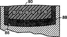
图6a是拉伸件的截面图;图6b是拉伸件的替换实施例的截面图;图6c是拉伸件的另一替换实施例的截面图;以及图6d是再一个替换实施例的截面图。6a is a cross-sectional view of a tensile member; FIG. 6b is a cross-sectional view of an alternative embodiment of a tensile member; FIG. 6c is a cross-sectional view of another alternative embodiment of a tensile member; and FIG. Sectional view.
图7是本发明一替换实施例的单一芯线的放大截面图,该芯线具有缠绕在中心股线上的六股股线;Figure 7 is an enlarged cross-sectional view of a single core wire having six strands wrapped around a center strand, in accordance with an alternate embodiment of the present invention;
图8是本发明的单一芯线的另一替换实施例的放大截面图;以及Figure 8 is an enlarged cross-sectional view of another alternative embodiment of a single core wire of the present invention; and
图9是本发明再一替换实施例的放大截面图。Figure 9 is an enlarged cross-sectional view of yet another alternative embodiment of the present invention.
实施本发明的最佳方案The best solution for implementing the present invention
图1表示了一个牵引式电梯系统12。该电梯系统12包括一个轿厢14、一个配重16、一个牵引驱动器18和一个主机20。牵引驱动器18包括一个将轿厢14和配重16相互连接的拉伸件22和一个牵引滑轮24。拉伸件22与滑轮24啮合,使得滑轮24转动时能够驱动拉伸件22以及轿厢14和配重16移动。主机20与滑轮24啮合以驱动滑轮24转动。尽管图中表示了一个齿轮式主机20,但也应该注意到,这种结构仅用于图示目的,本发明可以采用齿轮式主机或无齿轮主机。FIG. 1 shows a
图2更详细地表示了拉伸件22和滑轮24。拉伸件22是一个集成有位于公共覆盖层28内的多条芯线26的单独装置。每一绳索26都由高强度人造、非金属纤维(例如商用的芳族聚酰胺纤维)制成的平行或缠绕股线构成。芯线26长度相等,并在覆盖层28内的宽度方向上大致等间距布置,并在整个宽度上为线排列。覆盖层28由聚氨酯材料、最好是热塑型胺基甲酸乙酯制成,即以下述方式挤出并穿过多条芯线26,所述方式是,各个芯线26中的每一根都被加以限制而不能相对于其他芯线26移动。透明材料是另一替换实施例,由于它方便了用肉眼监测扁平绳索,所以更为有利。当然,从结构上讲,颜色并不重要。对于覆盖层28,如果有其他材料足以满足覆盖层的所需功能,即牵引、磨损、向芯线26传递牵引负载以及克服环境因素等的话,也可以采用这些材料。应该进一步理解到,如果其他材料不能满足或超过了热塑型胺基甲酸乙酯的机械性能的话,则不能完全达到本发明显著降低滑轮直径的附加有利效果。根据热塑型胺基甲酸乙酯的机械性能,牵引滑轮的直径可以降至100毫米或更小。覆盖层28限定了一个与牵引滑轮24的对应表面接触的啮合面30。Figure 2 shows the
如图6a所更清楚地表示的那样,拉伸件22的宽度为w,厚度为t1,宽度w是在相对于拉伸件22的长度方向呈横向的方向上测量的,厚度t1是在拉伸件22绕滑轮24的弯曲方向上测量的。每一芯线26的直径都为d并且相隔一段距离s。另外,覆盖层28中在芯线26和啮合面30之间的厚度定义为t2,在芯线26和相对表面之间的厚度定义为t3,这样,t1=t2+t3+d。As shown more clearly in Figure 6a, the
拉伸件22的整个尺寸使得其横截面上具有远大于1的尺寸比,其中尺寸比定义为宽度w与厚度t1之比或(尺寸比=w/t1)。例如在传统的圆形绳索中,通常圆形横截面对应的尺寸比为1。尺寸比越大,拉伸件22横截面的扁平度越大。使拉伸件22扁平化,就可以减小厚度t1并增大拉伸件22的宽度w,而不牺牲横截面积或承载能力。这种结构的结果是在拉伸件22的宽度方向上均分了绳索压力,并且相对于具有可比横截面积以及承载能力的圆形绳索来说,减小了最大绳索压力。如图2所示,对于具有五条设置在覆盖层28内的独立芯线26的拉伸件22来说,尺寸比大于5。尽管图示装置具有大于5的尺寸比,但仍应该相信,具有大于1的尺寸比、特别是具有大于2的尺寸比的拉伸件也会很有利。The overall size of the
相邻芯线26之间的间隔s取决于拉伸件22所用的材料和制造工艺,以及拉伸件22中绳索应力的分布情况。考虑到重量因素,很希望减小相邻芯线26之间的间隔s,从而减少芯线26之间的覆盖材料的用量。但是,考虑到绳索应力分布情况,应限制芯线26相互邻近的程度,以避免相邻芯线26之间的覆盖层28中产生超大应力。基于这些考虑,该间隔可以根据特定承载需求进行优化。The interval s between adjacent
覆盖层28的厚度t2取决于绳索应力分布和覆盖层28材料的磨损特性。如上所述,很希望避免在覆盖层28内产生超大应力,同时提供足够的材料来增大拉伸件22的预期寿命。The thickness t2 of the
覆盖层28的厚度t3取决于拉伸件22的使用情况。如图1所示,拉伸件22绕过单独的滑轮24,因此,顶面32并不与滑轮24啮合。在这种应用场合,厚度t3可以非常小,尽管当拉伸件22绕过滑轮24运行时,它必须足以承担拉力。还希望使拉伸件表面32具有沟槽以减小厚度t3中的张紧力。另一方面,如果拉伸件22用于下述电梯系统中,即该电梯系统需要使拉伸件22绕第二滑轮反向弯曲,则需要使厚度t3和厚度t2相等。在这种应用场合,拉伸件22的上表面32和下表面30都是啮合表面并承受相同的磨损和应力。The thickness t3 of the
各芯线26的直径d和芯线26的数量取决于特定的用途。如上所述,很希望保持厚度d尽可能地小,以增大柔性并减小芯线26中的应力。The diameter d of each
尽管在图2中表示了具有多条埋入覆盖层28内的圆形绳索26的情况,但拉伸件22也可以采用其他形式的独立绳索,包括那些考虑到费用、寿命或易于制造性等原因并具有大于1的尺寸比的绳索。这种实例包括椭圆形绳索34(图6b)、扁平或矩形绳索36(图6c)或图6d所示的贯穿拉伸件22宽度的单独扁平绳索38。图6d所示实施例的优点是绳索压力分布更加均匀,因此,拉伸件22中的最大绳索压力比其他结构中的绳索压力小。由于绳索包容在覆盖层内,又由于覆盖层限定了啮合面,所以对于牵引作用来说,绳索的实际形状不太重要,并且为了其他目的可以进行优化。Although in FIG. 2 there is shown a plurality of
在另一个优选实施例中,每一芯线26都最好由7股缠绕的股线制成,每一股线都由7根缠绕的金属丝构成。在本发明这种结构的优选实施例中,采用了高碳钢。这种钢最好经过冷拔并镀锌以达到公认的强度特性以及这种工艺的防腐蚀特性。覆盖层最好是醚基的聚氨酯材料并包括阻燃成分。In another preferred embodiment, each
在包含金属芯线的优选实施例中,参见图7,芯线26的每一股线27都包括七条金属丝,其中六条金属丝29缠绕在一条中央金属丝31的周围。每条芯线26都包括一条位于中央的股线27a和缠绕在中央股线27a周围的六条附加的外部股线27b。形成中央股线27a的各个金属丝29的缠绕构型最好是在一个方向上环绕中央股线27a的中央金属丝31,同时,外部股线27b的金属丝29在相反的方向上缠绕在外部股线27b的中央金属丝31周围。外部股线27b以与金属丝29缠绕在股线27a中的金属丝31周围的相同方向而缠绕在中央芯线27a的周围。例如,在一个实施例中,各条股线包括中央金属丝31(在中央股线27a),同时六条缠绕金属丝29以顺时针缠绕;外部股线27b中的金属丝29围绕它们各自的中央金属丝31逆时针缠绕,同时,从芯线26的层次来说,外部股线27b以顺时针方向缠绕在中央股线27a的周围。这种缠绕方向改善了在芯线的所有金属丝中的负载分配特性。In a preferred embodiment comprising a metal core wire, see FIG. 7 , each strand 27 of
为了成功运用本发明的实施例,采用非常小尺寸的金属丝29是很重要的。每一金属丝29和31的直径都小于0.25毫米,最好直径是在大约0.10毫米到0.20毫米的范围内。在特定实施例中,这些金属丝的直径为0.175毫米。采用小尺寸的金属丝很有利于应用小直径的滑轮。小直径的金属丝能够适应小直径滑轮的弯曲半径(直径约100毫米),而不会在扁平绳索的股线上施加过大的应力。由于在本发明的实施例中采用了总直径最好大约为1.6毫米的多条小芯线26,并将它们埋入扁平绳索弹性体,所以每条芯线上的压力明显比已有技术的绳索压力小。芯线压力降低至少n-1/2,其中n是对于给定负载和金属丝横截面积来说的扁平绳索中平行芯线的数目。In order to successfully operate embodiments of the present invention, it is important to use very small
在包含有由金属材料制成的芯线的结构的替换实施例中,参见图8,每条芯线26的中央股线37a的中央金属丝35具有更大的直径。例如,如果采用了前述实施例的金属丝29(0.175毫米),只有芯线的中央股线的中央金属丝35的直径将大约是0.20-0.22毫米。这种中央金属丝直径变化的效果是降低了环绕金属丝35的金属丝29之间的接触程度,以及降低了缠绕在股线37a周围的股线37b之间的接触程度。在这一实施例中,芯线26的直径将稍大于前述实施例中1.6毫米的直径。In an alternative embodiment of the structure comprising core wires made of metallic material, see FIG. 8 , the
在包含有由金属材料制成的芯线的结构的第三实施例中,参见图9,图8所示实施例的概念有所扩展,以进一步降低金属丝到金属丝、股线到股线的接触程度。这里采用了三种不同尺寸的金属丝来构造本发明的芯线。在该实施例中,最大的金属丝是中央股线200中的中央金属丝202。中间大小的直径的金属丝204环绕在中央股线200的中央金属丝202周围,因此构成了中央股线200的一部分。这种中间直径的金属丝204也是所有外部股线210的中央金属丝206的尺寸。这里采用的最小直径的金属丝以序号208表示。它们卷绕在每一外部股线210的每条金属丝206上。该实施例中,所有的金属丝的直径都小于0.25mm。在一个代表性实施例中,金属丝202可以是0.21mm;金属丝204可以是0.19mm;金属丝208可以是0.175mm。应该理解到,在该实施例中,金属丝204和206直径相等,只是为了表达位置信息而分别标号。应该注意到本发明并不仅限于直径相同的金属丝204和206。这里提供的所有金属丝直径都是示例性的,并且可以在使中央股线的外部金属丝之间的接触程度减小、使外部股线的外部金属丝之间的接触程度减小、以及使外部股线之间的接触程度减小的连接原理下加以重新布局。在这里提供的实施例中(仅用于示例目的),外部股线的外部金属丝之间的间距是0.014mm。In a third embodiment of a structure comprising a core wire made of metallic material, see FIG. 9, the concept of the embodiment shown in FIG. 8 is extended to further reduce wire-to-wire, strand-to-strand degree of contact. Here, three different sizes of metal wires are used to construct the core wire of the present invention. In this embodiment, the largest wire is the central wire 202 in the
再次参见图2,牵引滑轮24包括一个基体40和衬套42。基体40由铸铁制成并包括一对设置在滑轮24的相对侧以形成槽46的凸缘44。衬套42包括一具有牵引面50的基座48和一对由滑轮24的凸缘44支撑的法兰52。衬套42由聚氨酯材料制成,例如一起拥有的美国专利5,112,933所述的材料,或者与覆盖层28的啮合面30啮合以提供所需的牵引力和磨损特性的任何其他适合材料。因为更换拉伸件22或滑轮24的费用方面的原因,所以在牵引驱动器18中,很希望滑轮衬套42磨损而不是滑轮24或拉伸件22磨损。因此,在牵引驱动器18中,衬套42具有牺牲层的功能。通过粘结或任何其他传统的方法将衬套保持在槽46中并确定了用于接收拉伸件22的牵引面50。牵引面50具有直径D。牵引面50和啮合面30之间的啮合为驱动电梯系统12提供了牵引力。上述与拉伸件一起使用的滑轮的直径比已有技术中的直径明显减小。特别是,采用本发明扁平绳索的滑轮的直径可以减小到100mm或更小。本领域的技术人员可以立即认识到,这种滑轮直径的减小就允许使用更小的主机。实际上,对于典型的8人电梯来说,在例如低层建筑物的无齿轮应用场合下,主机尺寸可以降低到传统尺寸的1/4。这是因为对于100mm的滑轮来说,所需的扭矩降低到了大约为原来的1/4,电机的每分钟转速增加了。因此,主机费用降低了。Referring again to FIG. 2 ,
尽管图示装置具有衬套42,但对于本领域的技术人员来说,拉伸件22也可以与不具有衬套42的滑轮一起使用。作为替换实施例,衬套42可以通过在滑轮上涂覆一层选定材料,例如聚氨酯的方式代替,或者用由适当的合成材料制成或注塑形成的滑轮来代替。如果采用的话,这些替换实施例可更加经济有效,因为滑轮的尺寸减小了,并且简单地更换整个滑轮比更换滑轮衬套要更便宜。Although the illustrated device has a bushing 42, it will be apparent to those skilled in the art that the
滑轮24和衬套42的形状决定了容纳拉伸件22的空间54。凸缘44和衬套42的法兰52形成了拉伸件22和滑轮24之间的啮合边界并对啮合状态进行导引,以避免拉伸件22与滑轮24脱离啮合。The shape of the
图3表示了牵引驱动器18的替换实施例。在该实施例中,牵引驱动器18包括三个拉伸件56和牵引滑轮58。每个拉伸件56的结构都与上面参照图1和2所述的拉伸件22相同。牵引滑轮58包括一个基体62、一对设置在滑轮58相对侧的凸缘64、一对隔板66和三个衬套68。隔板66与凸缘64横向间隔设置并相互构成了容纳衬套68的三个槽70。就象参照图2所述的衬套42那样,每个衬套68包括一个确定了牵引面74以容纳拉伸件56之一的基座72和一对抵靠在凸缘64或隔板66上的法兰76。仍如图2,衬套42足够宽,使得拉伸件的边缘和衬套42的法兰76之间形成空间54。FIG. 3 shows an alternative embodiment of the
图4和5表示了牵引驱动器18的另一种结构。图4表示了具有凸面形状的牵引面88的滑轮86。牵引面88的形状迫使扁平拉伸元件90在工作时保持对中。图5表示了具有由被包容的芯线96限定的轮廓啮合面94的拉伸件92。牵引滑轮98包括衬套100,该衬套100具有与拉伸件92的轮廓互补的轮廓拉伸面102。这种互补结构可以在啮合时对拉伸件92进行导引并提高拉伸件92和牵引滑轮98之间的牵引力。4 and 5 show another construction of the
采用本发明的拉伸件和牵引驱动器可以明显地减小最大绳索压力,并且相应地减小滑轮直径和所需扭矩。最大绳索压力的减小是拉伸件的横截面积的尺寸比大于1的结果。对于这种结构,假设拉伸件具有图6d的结构,则最大绳索压力的大致计算公式如下:Using the tensioner and traction drive of the present invention can significantly reduce the maximum rope pressure and correspondingly reduce the pulley diameter and required torque. The reduction in maximum rope pressure is a result of the dimension ratio of the cross-sectional areas of the tensile members being greater than one. For this structure, assuming that the tensile member has the structure of Figure 6d, the approximate calculation formula of the maximum rope pressure is as follows:
P最大≡(2F/Dw)Pmax≡ (2F/Dw)
其中,F是拉伸件中的最大拉力。对于图6a-c的其他结构来说,尽管由于各绳索不同而稍稍高些,最大绳索压力仍大致相同。对于圆形槽中的圆形绳索来说,最大绳索压力的计算公式如下:where F is the maximum tensile force in the stretched part. For the other configurations of Figures 6a-c, the maximum rope pressure is about the same, although slightly higher due to the different ropes. For a round rope in a round groove, the maximum rope pressure is calculated as follows:
P最大≡(2F/Dd)×(4/π)Pmax≡ (2F/Dd)×(4/π)
假设直径和拉伸力水平相当,因子(4/π)导致了最大绳索压力增加了至少27%。特别明显的是,宽度w比芯线直径d大很多,这导致了最大绳索压力大大降低。如果传统绳索槽有切口,则最大绳索压力就更大,因此采用扁平拉伸件结构就能相对更大地减小最大绳索压力。本发明拉伸件的其他优点是,拉伸件的厚度t1可以比相同的承载能力圆形绳索的直径d小很多。与传统绳索相比,这就增加了拉伸件的柔性。Assuming comparable diameters and tensile force levels, the factor (4/π) results in an increase in maximum rope pressure of at least 27%. It is particularly evident that the width w is much larger than the core diameter d, which leads to a considerable reduction of the maximum rope pressure. If conventional rope grooves are notched, the maximum rope pressure is greater, so the use of a flat tensile member structure can reduce the maximum rope pressure relatively more. A further advantage of the tensile element according to the invention is that the thickness t1 of the tensile element can be considerably smaller than the diameter d of a round rope of the same load-bearing capacity. This increases the flexibility of the tensile member compared to conventional ropes.
尽管已依据本发明的实施例对本发明进行了图示和描述,但本技术领域的普通技术人员应当知道,在不脱离本发明的精神和范围的情况下可以对其作出多种改变、省略和增加。Although the present invention has been illustrated and described according to the embodiments of the present invention, those skilled in the art should understand that various changes, omissions and modifications can be made thereto without departing from the spirit and scope of the present invention. Increase.
Claims (68)
Translated fromChineseApplications Claiming Priority (6)
| Application Number | Priority Date | Filing Date | Title |
|---|---|---|---|
| US09/031,108US6401871B2 (en) | 1998-02-26 | 1998-02-26 | Tension member for an elevator |
| US09/031,108 | 1998-02-26 | ||
| US09/031108 | 1998-02-26 | ||
| US09/218990 | 1998-12-22 | ||
| US09/218,990 | 1998-12-22 | ||
| US09/218,990US6739433B1 (en) | 1998-02-26 | 1998-12-22 | Tension member for an elevator |
Related Child Applications (1)
| Application Number | Title | Priority Date | Filing Date |
|---|---|---|---|
| CNB2006100818947ADivisionCN100564222C (en) | 1998-02-26 | 1999-02-19 | Elevator device |
Publications (2)
| Publication Number | Publication Date |
|---|---|
| CN1292051Atrue CN1292051A (en) | 2001-04-18 |
| CN1267604C CN1267604C (en) | 2006-08-02 |
Family
ID=26706847
Family Applications (1)
| Application Number | Title | Priority Date | Filing Date |
|---|---|---|---|
| CNB998033626AExpired - LifetimeCN1267604C (en) | 1998-02-26 | 1999-02-19 | Tensions, traction drives and pulleys and pulley bushings for elevators |
Country Status (9)
| Country | Link |
|---|---|
| US (1) | US9352935B2 (en) |
| EP (4) | EP1060305B2 (en) |
| CN (1) | CN1267604C (en) |
| BR (1) | BR9908228B1 (en) |
| DE (7) | DE29924759U1 (en) |
| ES (3) | ES2252933T5 (en) |
| PT (1) | PT1060305E (en) |
| TW (1) | TW458938B (en) |
| WO (3) | WO1999043885A1 (en) |
Cited By (6)
| Publication number | Priority date | Publication date | Assignee | Title |
|---|---|---|---|---|
| CN1323929C (en)* | 2001-11-23 | 2007-07-04 | 因温特奥股份公司 | elevator system |
| CN1585695B (en)* | 2001-11-13 | 2010-12-15 | 奥蒂斯电梯公司 | Elevator belt assembly with noise and vibration reducing grooveless jacket arrangement |
| CN101349023B (en)* | 2008-08-27 | 2013-02-06 | 葛文国 | Elevator drawing belt and transmission method thereof |
| CN101827772B (en)* | 2007-10-17 | 2013-04-03 | 因温特奥股份公司 | Elevator having a suspension |
| CN110785368A (en)* | 2017-04-28 | 2020-02-11 | 阿力马克集团管理公司 | Tensioner |
| CN114057073A (en)* | 2020-08-01 | 2022-02-18 | 奥的斯电梯公司 | High friction and wear resistant elevator sheave bushings |
Families Citing this family (55)
| Publication number | Priority date | Publication date | Assignee | Title |
|---|---|---|---|---|
| JP2001524060A (en) | 1996-12-30 | 2001-11-27 | コネ コーポレイション | Elevator rope equipment |
| US6633159B1 (en)* | 1999-03-29 | 2003-10-14 | Otis Elevator Company | Method and apparatus for magnetic detection of degradation of jacketed elevator rope |
| US6601828B2 (en) | 2001-01-31 | 2003-08-05 | Otis Elevator Company | Elevator hoist machine and related assembly method |
| US6295799B1 (en)* | 1999-09-27 | 2001-10-02 | Otis Elevator Company | Tension member for an elevator |
| US7137483B2 (en) | 2000-03-15 | 2006-11-21 | Hitachi, Ltd. | Rope and elevator using the same |
| FI118732B (en)* | 2000-12-08 | 2008-02-29 | Kone Corp | Elevator |
| FR2823734B1 (en)* | 2001-04-19 | 2007-04-20 | Serge Arnoult | ELEVATOR INSTALLATION PROVIDED WITH INDEPENDENT TRAINING MEANS AND MEANS OF SUSPENSION |
| BE1015637A3 (en)* | 2001-05-23 | 2005-07-05 | Otis Elevator Co | Traction element for a lift. |
| US9573792B2 (en) | 2001-06-21 | 2017-02-21 | Kone Corporation | Elevator |
| SK286814B6 (en)* | 2001-06-21 | 2009-06-05 | Kone Corporation | Elevator |
| DE10154171A1 (en)* | 2001-11-05 | 2003-05-28 | Otis Elevator Co | Hydraulic lift (elevator) modernizing process involves dismantling drive and cable, fitting counterweight with pulley and pulley drive unit, diverting pulley and fixing devices |
| US20030121729A1 (en)* | 2002-01-02 | 2003-07-03 | Guenther Heinz | Lift belt and system |
| FI119234B (en) | 2002-01-09 | 2008-09-15 | Kone Corp | Elevator |
| EP1553039B1 (en)* | 2004-01-07 | 2013-12-25 | Inventio AG | Drive for an elevator |
| JP4895500B2 (en) | 2004-01-07 | 2012-03-14 | インベンテイオ・アクテイエンゲゼルシヤフト | Elevator equipment drive device and method for replacing elevator equipment drive device |
| US20100018810A1 (en)* | 2005-03-01 | 2010-01-28 | Mitsubishi Electric Corporation | Elevator apparatus |
| DE102006020633B3 (en)* | 2006-05-04 | 2007-11-29 | Contitech Antriebssysteme Gmbh | flat belts |
| US9150384B2 (en)* | 2006-06-26 | 2015-10-06 | Otis Elevator Company | Elevator installation with reduced hoistway dimensions |
| EP1886794B1 (en)* | 2006-08-11 | 2010-02-03 | Inventio Ag | Lifting belt for an elevator and method of manufacturing this lifting belt |
| US20080116014A1 (en)* | 2006-08-11 | 2008-05-22 | Ernst Ach | Elevator installation with a belt, belt for such an elevator installation, method of producing such a belt, composite of such belts and method for assembly of such a composite in an elevator installation |
| EP1886957A1 (en) | 2006-08-11 | 2008-02-13 | Inventio Ag | Lift belt for a lift system and method for manufacturing such a lift belt |
| ES2294944B1 (en) | 2006-09-25 | 2009-02-16 | Orona S. Coop | SUSPENSION AND TRACTION ELEMENT FOR LIFTING AND LIFTING EQUIPMENT. |
| EP1905892B1 (en)* | 2006-09-29 | 2011-11-16 | Inventio AG | Synthetic fibre rope, lift installation with such a synthetic fibre rope and method for making a synthetic fibre rope |
| SG141343A1 (en)* | 2006-09-29 | 2008-04-28 | Inventio Ag | Synthetic fibre cable and lift installation with such a synthetic fibre cable |
| EP1975111A1 (en)* | 2007-03-28 | 2008-10-01 | Inventio Ag | Lift belt, manufacturing method for such a lift belt and lift system with such a belt |
| DE202008001786U1 (en) | 2007-03-12 | 2008-12-24 | Inventio Ag | Elevator installation, suspension element for an elevator installation and device for producing a suspension element |
| ES2425933T3 (en)* | 2007-09-27 | 2013-10-18 | Otis Elevator Company | An elevator load support member |
| ES2856889T3 (en) | 2008-08-15 | 2021-09-28 | Otis Elevator Co | Polymer sheath and cord assembly that has a flame retardant in the polymer sheath material |
| ES2476260T3 (en) | 2008-11-14 | 2014-07-14 | Otis Elevator Company | Elevator belt and corresponding manufacturing procedure |
| FI125142B (en)* | 2009-07-08 | 2015-06-15 | Kone Corp | Line to lifting device, rope arrangement, lift and procedure |
| CN102869596B (en) | 2010-04-12 | 2016-03-23 | 因温特奥股份公司 | For the suspension apparatus of elevator system |
| FI124541B (en) | 2011-05-18 | 2014-10-15 | Kone Corp | Hissarrangemeng |
| JP5815854B2 (en) | 2011-06-10 | 2015-11-17 | オーチス エレベータ カンパニーOtis Elevator Company | Elevator tension member |
| FI125114B (en) | 2011-09-15 | 2015-06-15 | Kone Corp | Suspension and control device for an elevator |
| WO2013053379A1 (en)* | 2011-10-10 | 2013-04-18 | Kone Corporation | Heated hoisting members |
| JP2015510049A (en)* | 2012-01-12 | 2015-04-02 | オーチス エレベータ カンパニーOtis Elevator Company | Protective covering for cord |
| FI123534B (en) | 2012-02-13 | 2013-06-28 | Kone Corp | Rope for a lifting device, elevator and method for making a rope |
| EP2749519B1 (en)* | 2012-12-27 | 2020-07-22 | KONE Corporation | Elevator with a non-metallic fibers belt-like ropes. |
| PL2799217T3 (en)* | 2013-04-30 | 2015-08-31 | Kone Corp | A method for manufacturing a rope, a rope and an elevator |
| EP2878563B1 (en)* | 2013-11-29 | 2017-03-22 | KONE Corporation | A rope terminal assembly and an elevator |
| CN103803383B (en)* | 2013-12-23 | 2016-11-23 | 西子奥的斯电梯有限公司 | A kind of elevator traction system |
| EP3200937B1 (en) | 2014-10-03 | 2019-11-06 | Flowserve Management Company | Non-metallic belt-driven crosshead drive system for hydraulic decoking and method for the operation thereof |
| EP3025998A1 (en)* | 2014-11-25 | 2016-06-01 | Inventio AG | Pulley of an elevator system. |
| EP3310701B1 (en) | 2015-06-17 | 2019-08-07 | Inventio AG | Lift system comprising a pulley, whose contact surface comprises an anisotropic structure. |
| EP3305707A1 (en)* | 2016-10-06 | 2018-04-11 | Inventio AG | Traction belt misalignment indicator |
| US10472210B2 (en)* | 2016-11-07 | 2019-11-12 | Otis Elevator Company | Load bearing member for an elevator system having a metalized polymer coating |
| US10189678B2 (en)* | 2017-04-11 | 2019-01-29 | Thyssenkrupp Elevator Ag | Elevator strip bonded end termination |
| WO2018198240A1 (en)* | 2017-04-26 | 2018-11-01 | 三菱電機株式会社 | Elevator, suspension body therefor, and production method for suspension body |
| US11970368B2 (en)* | 2018-06-18 | 2024-04-30 | Otis Elevator Company | Elevator system belt |
| US10766746B2 (en) | 2018-08-17 | 2020-09-08 | Otis Elevator Company | Friction liner and traction sheave |
| CN109630613B (en)* | 2019-01-07 | 2023-10-20 | 江苏华宏科技股份有限公司 | Regenerated balancing weight and preparation method thereof |
| US11814788B2 (en) | 2019-04-08 | 2023-11-14 | Otis Elevator Company | Elevator load bearing member having a fabric structure |
| US11117787B2 (en)* | 2019-07-22 | 2021-09-14 | Otis Elevator Company | Elevator sheave liner |
| DE112019007977T5 (en)* | 2019-12-18 | 2022-09-29 | Mitsubishi Electric Corporation | ELEVATOR |
| US11447369B2 (en)* | 2020-05-12 | 2022-09-20 | Otis Elevator Company | Electrically heated elevator tension member |
Family Cites Families (132)
| Publication number | Priority date | Publication date | Assignee | Title |
|---|---|---|---|---|
| US582171A (en) | 1897-05-11 | Winding apparatus | ||
| BE568737A (en)* | ||||
| US1047330A (en)† | 1912-12-17 | Otis Elevator Co | Traction-elevator. | |
| GB1052264A (en) | 1900-01-01 | |||
| USRE15737E (en) | 1923-12-25 | Sheave | ||
| US444447A (en) | 1891-01-13 | Charles a | ||
| GB1051587A (en) | 1900-01-01 | |||
| BE501611A (en) | ||||
| US1132769A (en) | 1907-06-17 | 1915-03-23 | Otis Elevator Co | Traction-elevator. |
| US1011423A (en)* | 1908-03-27 | 1911-12-12 | Otis Elevator Co | Belt-drive elevator. |
| US975790A (en) | 1908-11-25 | 1910-11-15 | Charles O Pearson | Multiple metallic belt for traction-elevators. |
| US1164115A (en) | 1909-01-21 | 1915-12-14 | Charles O Pearson | Traction-elevator. |
| US1035230A (en) | 1911-10-24 | 1912-08-13 | Charles O Pearson | Traction-elevator. |
| US1237321A (en)* | 1914-08-25 | 1917-08-21 | Gen Elevator Company | Electric elevator system. |
| US1477886A (en) | 1918-08-28 | 1923-12-18 | Goodyear Tire & Rubber | Belt and the like |
| US1475250A (en) | 1922-02-07 | 1923-11-27 | Otis Elevator Co | Interwoven flat-belt-drive apparatus |
| US1632512A (en) | 1922-09-23 | 1927-06-14 | United Electric Company | Pulley |
| US1748100A (en) | 1928-01-26 | 1930-02-25 | Edward S Avery | Coated pulley |
| US2017149A (en) | 1931-08-08 | 1935-10-15 | Galloway Engineering Company L | Rope sheave |
| US2326670A (en) | 1941-08-21 | 1943-08-10 | Jr Joseph C Patterson | Sheave and pressure rider |
| US2526324A (en)* | 1944-08-08 | 1950-10-17 | Lockheed Aircraft Corp | Power transmitting belt |
| US2625373A (en) | 1948-10-25 | 1953-01-13 | Gerald R Hunt | Line holder for winches |
| US2685801A (en) | 1952-02-28 | 1954-08-10 | Tishman David | Sheave tread |
| DE1679881U (en)† | 1953-06-20 | 1954-07-15 | Stahl Maschinenfabrik R | POWER PLANT FOR ELECTRIC LIFTS, ESPECIALLY FOR LIGHT LOADS. |
| DE1032496B (en) | 1954-01-18 | 1958-06-19 | Joseph Tepper Maschinenfabrik | Elevator system for traction drive |
| DE1777764U (en)† | 1957-08-27 | 1958-11-13 | J H Deussen Soehne G M B H | FOERDER OR DRIVE BELT MADE OF TEXTILES, LEATHER, RUBBER, PLASTIC OD. DGL. |
| US3177733A (en) | 1961-10-19 | 1965-04-13 | Takasago Gomu Kogyo Kabushikik | Belt transmission device |
| US3148710A (en) | 1961-12-18 | 1964-09-15 | Us Rubber Co | Belting fabric |
| US3174585A (en)† | 1962-08-13 | 1965-03-23 | Otis Elevator Co | Elevator hoisting mechanism |
| US3279762A (en)* | 1964-03-11 | 1966-10-18 | Otis Elevator Co | Noise abating and traction improving elevator sheave |
| GB1116923A (en) | 1964-08-20 | 1968-06-12 | British Ropes Ltd | Improvements in or relating to ropes, strands and cores |
| DE1497190B2 (en) | 1965-10-23 | 1975-03-06 | Philips Patentverwaltung Gmbh, 2000 Hamburg | Electrostatic image development process using liquids |
| GB1182593A (en) | 1965-12-09 | 1970-02-25 | British Ropes Ltd | Improvements in or relating to Rope, Strand or the Like |
| GB1184997A (en)† | 1968-03-22 | 1970-03-18 | Gates Rubber Co | Power Transmission Belt |
| JPS4815497Y1 (en) | 1969-02-14 | 1973-04-28 | ||
| GB1295718A (en) | 1970-02-04 | 1972-11-08 | ||
| GB1362514A (en)* | 1970-03-16 | 1974-08-07 | Teleflex Ltd | Winches |
| HU172582B (en) | 1971-03-11 | 1978-10-28 | Istvan Balint | Collecting control for elevators on semicondur devices |
| DE2136540A1 (en) | 1971-07-22 | 1973-02-01 | Rudolf Dr Ing Vogel | ELEVATOR |
| LU64779A1 (en) | 1972-02-15 | 1972-07-04 | ||
| US3802589A (en)* | 1972-05-05 | 1974-04-09 | Clark Equipment Co | Dual extensible reach truck |
| NL7214547A (en) | 1972-10-27 | 1974-05-01 | ||
| DE2333120A1 (en)* | 1973-06-29 | 1975-01-23 | Rudolf Dr Ing Vogel | DRIVING AND / OR REVERSING ROLLERS FOR STEEL BELTS AS A CARRIER FOR TRANSPORT MEANS |
| JPS604312B2 (en) | 1973-07-17 | 1985-02-02 | 住友電気工業株式会社 | Steel cord for reinforcement |
| US3824777A (en) | 1973-10-05 | 1974-07-23 | Amsted Ind Inc | Lubricated plastic impregnated wire rope |
| FI50864C (en) | 1974-05-28 | 1976-08-10 | Kone Oy | Elevator. |
| DE2455273C3 (en) | 1974-11-22 | 1978-01-19 | Feiten & Guilleaume Carlswerk AG, 5000 Köln | Plastic crane rope |
| FR2293392A1 (en) | 1974-12-04 | 1976-07-02 | December 4 Drotmuevek | Self-operating cable clamp - has lifting cable and counterweight cable with conveying basket at other end |
| SU505764A1 (en)* | 1974-12-30 | 1976-03-05 | Всесоюзный научно-исследовательский институт организации и механизации шахтного строительства | Flat lifting rope |
| US3934482A (en) | 1975-01-27 | 1976-01-27 | The United States Of America As Represented By The Secretary Of The Navy | Cable traction sheave |
| CA1041385A (en) | 1975-02-24 | 1978-10-31 | Tadao Senoo | Rope and method for forming same |
| US4030569A (en) | 1975-10-07 | 1977-06-21 | Westinghouse Electric Corporation | Traction elevator system having cable groove in drive sheave formed by spaced, elastically deflectable metallic ring members |
| US4013142A (en)* | 1975-10-07 | 1977-03-22 | Westinghouse Electric Corporation | Elevator system having a drive sheave with rigid but circumferentially compliant cable grooves |
| NO760684L (en) | 1976-03-02 | 1977-09-05 | Elkem Spigerverket As | ST} LTAU WITH LOADING FIBER ELEMENTS. |
| JPS593011B2 (en) | 1978-05-23 | 1984-01-21 | 株式会社フジクラ | flat power supply cable |
| US4202164A (en) | 1978-11-06 | 1980-05-13 | Amsted Industries Incorporated | Lubricated plastic impregnated aramid fiber rope |
| US4344278A (en) | 1980-05-30 | 1982-08-17 | Projected Lubricants, Inc. | Lubricated wire rope |
| GB2092629B (en)* | 1981-02-06 | 1984-09-19 | Bekaert Sa Nv | Improvements in fatigue resistant cables |
| JPS57137285A (en) | 1981-02-17 | 1982-08-24 | Mitsubishi Electric Corp | Hoisting device for elevator |
| US4402488A (en) | 1981-11-13 | 1983-09-06 | Westinghouse Electric Corp. | Sheave |
| JPS58130874A (en)* | 1982-01-25 | 1983-08-04 | 三菱電機株式会社 | Driving device for elevator |
| US4422286A (en) | 1982-02-08 | 1983-12-27 | Amsted Industries Incorporated | Fiber reinforced plastic impregnated wire rope |
| JPS58140977U (en) | 1982-03-15 | 1983-09-22 | 三菱電機株式会社 | Hoisting machine for elevator |
| US4388837A (en) | 1982-06-28 | 1983-06-21 | Bender Emil A | Positive engagement fail safe mechanism and lift belt construction for long stroke, well pumping unit |
| JPS5922878A (en)* | 1982-07-29 | 1984-02-06 | 三菱電機株式会社 | Elevator drive device |
| US4716989A (en) | 1982-08-04 | 1988-01-05 | Siecor Corporation | Elevator compensating cable |
| US4724929A (en) | 1982-08-04 | 1988-02-16 | Siecor Corporation | Elevator compensating cable |
| JPS5958261A (en) | 1982-09-28 | 1984-04-03 | Hitachi Ltd | Driving sheave |
| JPS5964490A (en) | 1982-10-04 | 1984-04-12 | 三菱電機株式会社 | Elevator hoisting device |
| US4445593A (en) | 1982-10-15 | 1984-05-01 | Siecor Corporation | Flat type feeder cable |
| JPS59102780U (en) | 1982-12-25 | 1984-07-11 | 株式会社三渡工業所 | Automatic door closing device |
| GB2134209B (en)* | 1982-12-30 | 1986-03-12 | Blacks Equip Ltd | Belts or ropes suitable for haulage and lifts |
| US4519262A (en) | 1983-04-29 | 1985-05-28 | Baker Oil Tools, Inc. | Positive engagement safety mechanism and lift belt construction for long stroke, well pumping unit |
| US4534163A (en) | 1983-09-19 | 1985-08-13 | New England Ropes, Inc. | Rope or cable and method of making same |
| US4624097A (en) | 1984-03-23 | 1986-11-25 | Greening Donald Co. Ltd. | Rope |
| US4589861A (en) | 1984-05-22 | 1986-05-20 | Itek Graphix Corp. | Simple recording head drive having virtually zero backlash or slippage |
| GB2162283A (en) | 1984-07-26 | 1986-01-29 | Blacks Equip Ltd | Winding shaft for mine winders, hoists and lifts |
| US4609181A (en) | 1984-08-24 | 1986-09-02 | General Telephone Company Of The Northwest | Method of pulling optical fiber cable |
| US4605035A (en)* | 1984-09-14 | 1986-08-12 | Lavrids Knudsen Maskinefabrik A/S | Double seat valve |
| DE3503214A1 (en) | 1985-01-31 | 1986-08-07 | INA Wälzlager Schaeffler KG, 8522 Herzogenaurach | COMPONENT CONSTRUCTED FROM A POLYMER MATERIAL REINFORCED BY FIBER-SHAPED FILLERS |
| EP0228725A1 (en) | 1985-12-02 | 1987-07-15 | N.V. Bekaert S.A. | A woven fabric to increase the stiffness of an elastomeric belt and the elastomeric belt thus obtained |
| JPH0797165B2 (en) | 1986-04-10 | 1995-10-18 | 日本電信電話株式会社 | Lens connector type feedthrough |
| US4887656A (en) | 1986-06-20 | 1989-12-19 | Germain Verbauwhede | Woven fabric with bias weft and tire reinforced by same |
| FR2617204B1 (en)† | 1987-06-26 | 1989-10-27 | Staubli Sa Ets | DEVICE FOR COUPLING THE RAIL FRAMES TO THE TRANSMISSION ELEMENTS OF A MECHANICS FOR THE FORMATION OF A CROWD |
| JPH01150070A (en) | 1987-12-04 | 1989-06-13 | Mitsubishi Electric Corp | Pulley and its manufacture |
| JP2614747B2 (en) | 1988-06-10 | 1997-05-28 | 日本オーチス・エレベータ株式会社 | Elevator rope damping device |
| JPH0642119Y2 (en) | 1988-10-25 | 1994-11-02 | 日本メクトロン株式会社 | Flat belt |
| JP2659072B2 (en) | 1988-12-16 | 1997-09-30 | 住友電気工業株式会社 | Steel cord for rubber reinforcement |
| JPH0770962B2 (en) | 1988-12-21 | 1995-07-31 | 松下電器産業株式会社 | Digital filter |
| US4947636A (en) | 1989-02-13 | 1990-08-14 | The Goodyear Tire & Rubber Company | Metal wire cord for elastomer reinforcement |
| JPH02233492A (en) | 1989-02-28 | 1990-09-17 | Otis Elevator Co | Laterally hung structure of elevator cage |
| US5149057A (en) | 1989-03-09 | 1992-09-22 | Baker Hughes Incorporated | Tape drive with self-expanding coils for sludge collector |
| US5129866A (en)† | 1989-05-22 | 1992-07-14 | Fenrir Ag | Method and device for producing endless drive belts |
| US5033586A (en)* | 1990-07-11 | 1991-07-23 | Otis Elevator Company | Construction elevator assembly |
| JPH0489787A (en)* | 1990-08-01 | 1992-03-23 | Mitsubishi Electric Corp | elevator drive system |
| US5112933A (en)* | 1991-04-16 | 1992-05-12 | Otis Elevator Company | Ether-based polyurethane elevator sheave liner-polyurethane-urea made from polyether urethane prepolymer chain extended with polyester/diamine blend |
| GB9116626D0 (en) | 1991-08-01 | 1991-09-18 | Univ Strathclyde | Improvements in and relating to ropes |
| EP0633349B1 (en) | 1991-12-27 | 1999-03-31 | Nippon Cable System Inc. | Rope for operating |
| FI96302C (en) | 1992-04-14 | 1996-06-10 | Kone Oy | Traction sheave elevator |
| DE9205254U1 (en)* | 1992-04-15 | 1992-06-17 | C. Haushahn Gmbh & Co, 70469 Stuttgart | Drive for rope lifts |
| US5222919A (en) | 1992-05-29 | 1993-06-29 | Calcomp Inc. | All plastic idler pulley assembly |
| CA2109904C (en)† | 1992-12-18 | 2004-09-14 | Pol Bruyneel | Multi-strand steel cord |
| ATE154674T1 (en) | 1993-03-05 | 1997-07-15 | Inventio Ag | ROPE END CONNECTION FOR A PLASTIC ROPE |
| FI94123C (en) | 1993-06-28 | 1995-07-25 | Kone Oy | Traction sheave elevator |
| FR2707309B1 (en) | 1993-07-09 | 1995-08-11 | Trefileurope France Sa | Lifting cable. |
| FI95902C (en)* | 1993-10-04 | 1996-04-10 | Kone Oy | Machine room for elevator and mounting procedure for this |
| MXPA95001137A (en)† | 1994-03-02 | 2004-02-16 | Inventio Ag | CABLE AS A SUSPENSION MEANS FOR AN ELEVATOR. |
| DE19515351A1 (en) | 1994-05-04 | 1995-11-09 | Volkswagen Ag | Diverting roller for belt drive |
| CA2154422C (en) | 1994-08-29 | 2005-05-24 | Hans G. Blochle | Cable-clamping device for a synthetic fibre cable |
| JPH08121577A (en) | 1994-10-24 | 1996-05-14 | Mitsubishi Electric Corp | Resin pulley device |
| US5610217A (en)† | 1994-10-31 | 1997-03-11 | The Gates Corporation | Ethylene-alpha-olefin belting |
| FI96198C (en) | 1994-11-03 | 1996-05-27 | Kone Oy | Pinion Elevator |
| US5725074A (en)* | 1995-06-02 | 1998-03-10 | Inventio Ag | Apparatus for supporting and guiding an elevator |
| FI100791B (en) | 1995-06-22 | 1998-02-27 | Kone Oy | Traction sheave elevator |
| JPH0921084A (en)* | 1995-07-06 | 1997-01-21 | Yamamori Giken Kogyo Kk | Wire rope structure |
| US5792294A (en) | 1995-11-16 | 1998-08-11 | Otis Elevator Company | Method of replacing sheave liner |
| DE19632850C2 (en)* | 1996-08-14 | 1998-09-10 | Regina Koester | Traction sheave elevator without counterweight |
| US5881843A (en)* | 1996-10-15 | 1999-03-16 | Otis Elevator Company | Synthetic non-metallic rope for an elevator |
| ES2225925T3 (en)* | 1996-12-03 | 2005-03-16 | Inventio Ag | MODULAR DESIGN ELEVATOR. |
| US5845396A (en) | 1996-12-17 | 1998-12-08 | Pacesetter, Inc. | Co-radial, multi-polar coiled cable lead and method for making the same |
| AU7403798A (en)* | 1996-12-30 | 1998-07-31 | Kone Oy | Elevator rope arrangement |
| JP2001524060A (en)† | 1996-12-30 | 2001-11-27 | コネ コーポレイション | Elevator rope equipment |
| FR2759709B1 (en)* | 1997-02-18 | 1999-03-19 | Ugine Savoie Sa | STAINLESS STEEL FOR THE PREPARATION OF TREWNED WIRE, ESPECIALLY OF PNEUMATIC REINFORCEMENT WIRE AND PROCESS FOR MAKING THE SAID WIRE |
| EP0864688A1 (en)* | 1997-03-13 | 1998-09-16 | N.V. Bekaert S.A. | Push-pull cable with polymer coating |
| US6401871B2 (en) | 1998-02-26 | 2002-06-11 | Otis Elevator Company | Tension member for an elevator |
| DE29924747U1 (en) | 1998-02-26 | 2005-06-09 | Otis Elevator Co., Farmington | Elevator system with drive motor between elevator car and elevator shaft side wall |
| US6138799A (en) | 1998-09-30 | 2000-10-31 | Otis Elevator Company | Belt-climbing elevator having drive in counterweight |
| ES2204069T3 (en)* | 1998-06-16 | 2004-04-16 | Bridgestone Corporation | STEEL CABLE INTENDED FOR REINFORCEMENT OF RUBBER ITEMS. |
| JP2002167137A (en) | 2000-11-29 | 2002-06-11 | Toshiba Corp | elevator |
| FI117434B (en) | 2000-12-08 | 2006-10-13 | Kone Corp | Elevator and elevator drive wheel |
| FR2823734B1 (en) | 2001-04-19 | 2007-04-20 | Serge Arnoult | ELEVATOR INSTALLATION PROVIDED WITH INDEPENDENT TRAINING MEANS AND MEANS OF SUSPENSION |
| SK286814B6 (en) | 2001-06-21 | 2009-06-05 | Kone Corporation | Elevator |
- 1999
- 1999-02-19BRBRPI9908228-4Apatent/BR9908228B1/ennot_activeIP Right Cessation
- 1999-02-19WOPCT/US1999/003658patent/WO1999043885A1/enactiveIP Right Grant
- 1999-02-19DEDE29924759Upatent/DE29924759U1/ennot_activeExpired - Lifetime
- 1999-02-19DEDE29924761Upatent/DE29924761U1/ennot_activeExpired - Lifetime
- 1999-02-19ESES99908282.9Tpatent/ES2252933T5/ennot_activeExpired - Lifetime
- 1999-02-19EPEP99908282.9Apatent/EP1060305B2/ennot_activeExpired - Lifetime
- 1999-02-19CNCNB998033626Apatent/CN1267604C/ennot_activeExpired - Lifetime
- 1999-02-19DEDE69929587.4Tpatent/DE69929587T3/ennot_activeExpired - Lifetime
- 1999-02-19DEDE29924762Upatent/DE29924762U1/ennot_activeExpired - Lifetime
- 1999-02-19DEDE29924760Upatent/DE29924760U1/ennot_activeExpired - Lifetime
- 1999-02-19PTPT99908282Tpatent/PT1060305E/enunknown
- 1999-02-26TWTW088102949Apatent/TW458938B/ennot_activeIP Right Cessation
- 1999-02-26WOPCT/US1999/004226patent/WO1999043597A2/enactiveIP Right Grant
- 1999-02-26EPEP99909642Apatent/EP1037847B1/ennot_activeExpired - Lifetime
- 1999-02-26WOPCT/US1999/004225patent/WO1999043598A2/enactiveIP Right Grant
- 1999-02-26ESES99908522Tpatent/ES2247785T3/ennot_activeExpired - Lifetime
- 1999-02-26DEDE69927942Tpatent/DE69927942T2/ennot_activeExpired - Lifetime
- 1999-02-26EPEP99908522Apatent/EP1042210B1/ennot_activeExpired - Lifetime
- 1999-02-26EPEP05014449Apatent/EP1591403B1/ennot_activeExpired - Lifetime
- 1999-02-26DEDE69936187Tpatent/DE69936187T2/ennot_activeExpired - Lifetime
- 1999-02-26ESES99909642Tpatent/ES2285833T3/ennot_activeExpired - Lifetime
- 2004
- 2004-05-05USUS10/839,550patent/US9352935B2/ennot_activeExpired - Fee Related
Cited By (6)
| Publication number | Priority date | Publication date | Assignee | Title |
|---|---|---|---|---|
| CN1585695B (en)* | 2001-11-13 | 2010-12-15 | 奥蒂斯电梯公司 | Elevator belt assembly with noise and vibration reducing grooveless jacket arrangement |
| CN1323929C (en)* | 2001-11-23 | 2007-07-04 | 因温特奥股份公司 | elevator system |
| CN101827772B (en)* | 2007-10-17 | 2013-04-03 | 因温特奥股份公司 | Elevator having a suspension |
| CN101349023B (en)* | 2008-08-27 | 2013-02-06 | 葛文国 | Elevator drawing belt and transmission method thereof |
| CN110785368A (en)* | 2017-04-28 | 2020-02-11 | 阿力马克集团管理公司 | Tensioner |
| CN114057073A (en)* | 2020-08-01 | 2022-02-18 | 奥的斯电梯公司 | High friction and wear resistant elevator sheave bushings |
Also Published As
Similar Documents
| Publication | Publication Date | Title |
|---|---|---|
| CN1292051A (en) | Tension member for elevator | |
| CN1222656C (en) | Elevator tension member | |
| KR100607631B1 (en) | Tension member for an elevator | |
| US6295799B1 (en) | Tension member for an elevator | |
| KR101372778B1 (en) | Lift installation with a belt, belt for such a lift installation, method of producing such a belt, composite of such belts and method for assembly of such a composite in a lift installation | |
| JP5519607B2 (en) | Elevator tension member | |
| CN1902119A (en) | Elevator | |
| CN1329274C (en) | Machine-roomless elevator system with elevator machine mounted on elevator car | |
| RU2000124665A (en) | TENSION OPERATING ELEMENT, TRACTION DRIVE, PULLEY AND PULLEY BUSHING FOR LIFTING SYSTEM | |
| CN1189380C (en) | Elevator device and method for manufacturing main rope of elevator device | |
| CN1342130A (en) | Dual sheave rope climber using flat flexible ropes | |
| US10221043B2 (en) | Elevator suspension and/or driving arrangement | |
| CN208883256U (en) | Traction or lifting belt drive unit and traction or lifting belt and elevator device | |
| JP5244275B2 (en) | Elevator apparatus tension member and method of forming tension member | |
| RU2230143C2 (en) | Lifting system incorporating tension member and usage of tension member fo r transmitting of upward force to lifting system cabin | |
| HK1174320B (en) | Hoist unit and load-bearing medium for such a unit |
Legal Events
| Date | Code | Title | Description |
|---|---|---|---|
| C06 | Publication | ||
| PB01 | Publication | ||
| C10 | Entry into substantive examination | ||
| SE01 | Entry into force of request for substantive examination | ||
| C14 | Grant of patent or utility model | ||
| GR01 | Patent grant | ||
| C56 | Change in the name or address of the patentee | Owner name:OTIS ELEVATOR COMPANY Free format text:FORMER NAME: LTIS ELEVATOR CO. | |
| CP01 | Change in the name or title of a patent holder | Address after:American Connecticut Patentee after:Otis Elevator Co. Address before:American Connecticut Patentee before:Ltis Elevator Co. | |
| CX01 | Expiry of patent term | ||
| CX01 | Expiry of patent term | Granted publication date:20060802 |